JP4170177B2 - Power storage device - Google Patents
Power storage deviceInfo
- Publication number
- JP4170177B2 JP4170177B2 JP2003310594A JP2003310594A JP4170177B2 JP 4170177 B2 JP4170177 B2 JP 4170177B2 JP 2003310594 A JP2003310594 A JP 2003310594A JP 2003310594 A JP2003310594 A JP 2003310594A JP 4170177 B2 JP4170177 B2 JP 4170177B2
- Authority
- JP
- Japan
- Prior art keywords
- double layer
- electric double
- layer capacitor
- secondary battery
- charging
- Prior art date
- Legal status (The legal status is an assumption and is not a legal conclusion. Google has not performed a legal analysis and makes no representation as to the accuracy of the status listed.)
- Expired - Fee Related
Links
Images


Description
本発明は、繰り返し充放電可能な蓄電装置及びそれを備えた動力出力装置に関する。 The present invention relates to a power storage device that can be repeatedly charged and discharged and a power output device including the same.
従来の蓄電装置の一例が特開平6−264851号公報(特許文献1)に開示されている。この装置は、自動車用の蓄電装置であり、始動用蓄電池と負荷用蓄電池の2つの蓄電池を備えている。そして、例えばエンジン始動用のスタータモータのような瞬時負荷は始動用蓄電池に分担させ、例えばランプ類のような定常負荷は負荷用蓄電池に分担させている。これによって、始動用蓄電池は効率放電用、負荷用蓄電池は低率放電用の設計を可能とし、蓄電池の長寿命化を図っている。その他にも、特許文献2に示す自動車用蓄電装置が開示されている。
An example of a conventional power storage device is disclosed in JP-A-6-264851 (Patent Document 1). This device is a power storage device for automobiles, and includes two storage batteries, a start storage battery and a load storage battery. For example, an instantaneous load such as a starter motor for starting the engine is shared by the starting storage battery, and a steady load such as a lamp is shared by the load storage battery. As a result, the start-up storage battery can be designed for efficient discharge, and the load storage battery can be designed for low-rate discharge, thereby extending the life of the storage battery. In addition, an automobile power storage device disclosed in
しかし、このような蓄電池は電気化学反応を用いて負荷に供給するためのエネルギーを蓄積しているため、瞬時に取り出せる電力及び長寿命化には限界がある。したがって、この従来の蓄電装置においては、大電力を瞬時に取り出すこと及び長寿命化が困難であるという問題点がある。 However, since such a storage battery stores energy to be supplied to a load using an electrochemical reaction, there is a limit to the power that can be instantaneously extracted and the extension of life. Therefore, in this conventional power storage device, there is a problem that it is difficult to take out a large amount of power instantaneously and extend its life.
一方、繰り返し充放電可能な蓄電装置として、蓄電池以外に電気二重層キャパシタも利用されている。電気二重層キャパシタは電気化学反応を用いないため、大電力を瞬時に取り出すことが可能であり、かつ長寿命という特徴を有している。しかし、電気二重層キャパシタについては、蓄電エネルギーは電気化学反応を用いる蓄電池より劣り、大エネルギーを蓄積することが困難であるという問題点がある。 On the other hand, as a power storage device that can be repeatedly charged and discharged, an electric double layer capacitor is also used in addition to a storage battery. Since the electric double layer capacitor does not use an electrochemical reaction, a large electric power can be taken out instantaneously and has a long life. However, the electric double layer capacitor has a problem that the stored energy is inferior to that of a storage battery using an electrochemical reaction, and it is difficult to store large energy.
本発明は、大エネルギーを蓄積することができるとともに大電力を瞬時に取り出すことができ、さらに長寿命化を実現できる蓄電装置及びそれを備えた動力出力装置を提供することを目的とする。 SUMMARY OF THE INVENTION An object of the present invention is to provide a power storage device that can store a large amount of energy and can take out a large amount of electric power instantaneously, and can achieve a longer life, and a power output device including the power storage device.
このような目的を達成するために、本発明の参考例に係る蓄電装置は、第1の負荷と、該第1の負荷より駆動頻度が低くかつ駆動時の消費電力が大きい第2の負荷と、を駆動するための電力を供給可能な蓄電装置であって、電気二重層キャパシタと、該電気二重層キャパシタの充電を行うことが可能な二次電池と、該二次電池と該電気二重層キャパシタとの間に流れる電流を制限するための電流制限手段と、前記二次電池の電圧を昇圧して前記電気二重層キャパシタへ供給する昇圧回路と、を備え、前記第1の負荷を駆動するための電力は二次電池から供給され、前記第2の負荷を駆動するための電力は電気二重層キャパシタから供給されることを特徴とする。 In order to achieve such an object, a power storage device according to a reference example of the present invention includes a first load and a second load that is driven less frequently and consumes more power during driving than the first load. , An electric double layer capacitor, a secondary battery capable of charging the electric double layer capacitor, the secondary battery and the electric double layer Current limiting means for limiting a current flowing between the capacitor and a booster circuit that boosts the voltage of the secondary battery and supplies the boosted voltage to the electric double layer capacitor, and drives the first load The power for driving is supplied from a secondary battery, and the power for driving the second load is supplied from an electric double layer capacitor.
本発明の参考例によれば、二次電池に大エネルギーを蓄積することができるとともに電気二重層キャパシタから大電力を瞬時に取り出すことができる。さらに、本発明の参考例によれば、駆動頻度が低いものの瞬時に大電力の供給を要求される負荷については二次電池からではなく瞬時に大電力を取り出せる電気二重層キャパシタから電力が供給され、電流制限手段により二次電池と電気二重層キャパシタとの間に流れる電流が制限される。したがって、二次電池の大電流放電に起因した電圧変動を抑制することができるので、蓄電装置の長寿命化を実現できる。 According to the reference example of the present invention , a large amount of energy can be stored in the secondary battery, and a large amount of electric power can be instantaneously extracted from the electric double layer capacitor. Furthermore, according to the reference example of the present invention, power is supplied not from the secondary battery but from the electric double layer capacitor that can take out the high power instantaneously for the load that is required to supply high power instantaneously although the drive frequency is low. The current flowing between the secondary battery and the electric double layer capacitor is limited by the current limiting means. Therefore, voltage fluctuation due to large current discharge of the secondary battery can be suppressed, and thus the life of the power storage device can be extended.
さらに、本発明の参考例によれば、二次電池の電圧を昇圧して電気二重層キャパシタへ供給する昇圧回路を備えることにより、電気二重層キャパシタに蓄積できる電気エネルギーを増大させることができ、かつ第2の負荷を駆動する際の電流を低減させることができる。 Furthermore, according to the reference example of the present invention, it is possible to increase the electrical energy that can be stored in the electric double layer capacitor by providing a booster circuit that boosts the voltage of the secondary battery and supplies the boosted voltage to the electric double layer capacitor. And the electric current at the time of driving a 2nd load can be reduced.
第1の本発明に係る蓄電装置は、第1の負荷と、該第1の負荷より駆動頻度が低くかつ駆動時の消費電力が大きい第2の負荷と、を駆動するための電力を供給可能な蓄電装置であって、直列に接続された複数の電気二重層キャパシタと、該複数の電気二重層キャパシタの充電を行うことが可能な二次電池と、各電気二重層キャパシタの両端子間を磁気的に結合し、各電気二重層キャパシタの両端子間に略同一の誘起電圧を印加可能な充電用トランスと、該誘起電圧が各電気二重層キャパシタの両端子間に印加されるように、各電気二重層キャパシタと充電用トランスとの間の接続状態を切り換え可能な切換手段と、各電気二重層キャパシタと充電用トランスとの間の接続状態の切り換え制御を行う制御手段と、を備え、複数の電気二重層キャパシタは、二次電池の両端子間に接続された電気二重層キャパシタ及び二次電池の両端子間に接続されない電気二重層キャパシタによって構成され、二次電池を用いて複数の電気二重層キャパシタの充電を行う場合に、二次電池の両端子間に接続されない電気二重層キャパシタについては、前記制御手段により各電気二重層キャパシタと充電用トランスとの間の接続状態を切り換えることで、充電用トランスに発生する誘起電圧が印加されて充電が行われ、複数の電気二重層キャパシタ全体の充電電圧は二次電池の電圧より大きくなり、前記第1の負荷を駆動するための電力は二次電池から供給され、前記第2の負荷を駆動するための電力は複数の電気二重層キャパシタから供給されることを特徴とする。 The power storage device according to the first aspect of the present invention can supply power for driving the first load and the second load that is driven less frequently and consumes more power during driving than the first load. A plurality of electric double layer capacitors connected in series, a secondary battery capable of charging the plurality of electric double layer capacitors, and between both terminals of each electric double layer capacitor. A charging transformer that is magnetically coupled and can apply substantially the same induced voltage between both terminals of each electric double layer capacitor, and the induced voltage is applied between both terminals of each electric double layer capacitor, Switching means capable of switching the connection state between each electric double layer capacitor and the charging transformer, and control means for performing switching control of the connection state between each electric double layer capacitor and the charging transformer, Multiple electric double layer carriers Shita is composed of an electric double layer capacitor connected between both terminals of the secondary battery and an electric double layer capacitor not connected between both terminals of the secondary battery, and a plurality of electric double layer capacitors using the secondary battery. For the electric double layer capacitor that is not connected between both terminals of the secondary battery when charging, the control means switches the connection state between each electric double layer capacitor and the charging transformer so that the charging transformer The induced voltage generated in the capacitor is charged and charged, the charging voltage of the plurality of electric double layer capacitors is larger than the voltage of the secondary battery, and the power for driving the first load is from the secondary battery. The supplied electric power for driving the second load is supplied from a plurality of electric double layer capacitors.
第1の本発明によれば、各電気二重層キャパシタの両端子間に略同一の誘起電圧を印加することができるので、各電気二重層キャパシタの電圧が均等になるように充電を行うことができる。さらに、二次電池の両端子間に接続されない電気二重層キャパシタについても、充電用トランスに発生する誘起電圧が印加されることにより充電が行われるので、例えばDC−DCコンバータのような昇圧用の回路を用いることなく二次電池からの電圧を昇圧させて電気二重層キャパシタの充電を行うことができる。したがって、電気二重層キャパシタに蓄積できる電気エネルギーを増大させることができ、かつ第2の負荷を駆動する際の電流を低減させることができる。 According to the first aspect of the present invention, since substantially the same induced voltage can be applied between both terminals of each electric double layer capacitor, charging can be performed so that the voltage of each electric double layer capacitor becomes equal. it can. Furthermore, since the electric double layer capacitor that is not connected between both terminals of the secondary battery is charged by applying the induced voltage generated in the charging transformer, for example, for boosting such as a DC-DC converter. The electric double layer capacitor can be charged by boosting the voltage from the secondary battery without using a circuit. Therefore, the electrical energy that can be stored in the electric double layer capacitor can be increased, and the current when driving the second load can be reduced.
第2の本発明に係る蓄電装置は、第1の本発明に記載の装置であって、前記二次電池と該二次電池の両端子間に接続された電気二重層キャパシタとの間に流れる電流を制限するための電流制限手段を備えることを特徴とする。 A power storage device according to a second aspect of the present invention is the device according to the first aspect of the present invention, and flows between the secondary battery and an electric double layer capacitor connected between both terminals of the secondary battery. It is characterized by comprising current limiting means for limiting the current.
第2の本発明によれば、二次電池と電気二重層キャパシタとの間に流れる電流が制限されるので、二次電池の大電流放電に起因した電圧変動を抑制することができる。したがって、蓄電装置の長寿命化を実現できる。 According to the second aspect of the present invention, since the current flowing between the secondary battery and the electric double layer capacitor is limited, voltage fluctuation caused by the large current discharge of the secondary battery can be suppressed. Therefore, the life of the power storage device can be extended.
第3の本発明に係る蓄電装置は、第1または第2の本発明に記載の装置であって、前記充電用トランスは複数のトランスに分割されて設けられており、それらのトランス間が電気二重層キャパシタの両端子間を介して接続されていることを特徴とする。本発明の参考例に係る動力出力装置は、本発明の蓄電装置及び動力出力用の内燃機関を備えた動力出力装置であって、前記第2の負荷は内燃機関を始動可能な電動機であり、前記電気二重層キャパシタから供給される電力は、電動機が内燃機関を始動させるために消費されることを特徴とする。
A power storage device according to a third aspect of the present invention is the device according to the first or second aspect of the present invention, wherein the charging transformer is divided into a plurality of transformers, and the transformers are electrically connected. It is connected via both terminals of the double layer capacitor. A power output device according to a reference example of the present invention is a power output device including the power storage device of the present invention and an internal combustion engine for power output, wherein the second load is an electric motor capable of starting the internal combustion engine, The electric power supplied from the electric double layer capacitor is consumed by the electric motor for starting the internal combustion engine.
本発明の参考例によれば、瞬時に大電力を取り出すことのできる電気二重層キャパシタから供給される電力によって内燃機関を始動させることができるので、内燃機関の始動性を改善することができる。
According to the reference example of the present invention, since the internal combustion engine can be started by the electric power supplied from the electric double layer capacitor that can take out large electric power instantaneously, the startability of the internal combustion engine can be improved.
以下、本発明の実施の形態(以下実施形態という)を、図面に従って説明する。 Hereinafter, embodiments of the present invention (hereinafter referred to as embodiments) will be described with reference to the drawings.
(1)第1実施形態
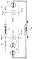
図1は、本発明の第1実施形態に係る蓄電装置を含む動力出力装置の構成の概略を示す図である。本実施形態に係る動力出力装置は、二次電池S101、電気二重層キャパシタC100、電流制限手段14、発電機16、内燃機関18及び電動機20を備えている。また、本実施形態に係る動力出力装置の適用例としては、内燃機関18を動力源として備えた車両用に用いた例が挙げられる。
(1) 1st Embodiment FIG. 1: is a figure which shows the outline of a structure of the power output device containing the electrical storage apparatus which concerns on 1st Embodiment of this invention. The power output apparatus according to this embodiment includes a secondary battery S101, an electric double layer capacitor C100, current limiting means 14, a
二次電池S101は、電気化学反応を用いて電気エネルギーを蓄積することができる。電気二重層キャパシタC100は、電気化学反応を用いずに電気エネルギーを蓄積することができ、二次電池S101の両端子間TM111,TM112に接続されている。なお、図示は省略しているが、電気二重層キャパシタC100は複数のキャパシタが直列あるいは直並列に接続されて構成されており、キャパシタ全体の耐電圧が二次電池S101の定格電圧より高くなっている。また、二次電池S101の端子TM112は接地されている。 The secondary battery S101 can store electrical energy using an electrochemical reaction. The electric double layer capacitor C100 can store electric energy without using an electrochemical reaction, and is connected to both terminals TM111 and TM112 of the secondary battery S101. Although not shown, the electric double layer capacitor C100 is configured by connecting a plurality of capacitors in series or in series and parallel, and the withstand voltage of the entire capacitor is higher than the rated voltage of the secondary battery S101. Yes. Further, the terminal TM112 of the secondary battery S101 is grounded.
電流制限手段14は、二次電池S101と電気二重層キャパシタC100との間に流れる電流を制限するために、二次電池S101と電気二重層キャパシタC100との間に設けられている。電流制限手段14の具体的な構成の一例については、抵抗のみによって本発明の電流制限手段14を実現することができる。
The
動力出力用の内燃機関18は、その出力軸に連結されている例えば車輪等の負荷(図示せず)に動力を出力可能である。また、内燃機関18の運転時には、発電機16が発電状態に駆動される。
The
二次電池S101の両端子TM111,TM112間には、発電機16がスイッチ32を介して接続されている。スイッチ32が導通状態(イグニッションのオン時)にあり発電機16が発電状態に運転されているときは、発電機16によって二次電池S101の充電を行うことができる。
A
電気二重層キャパシタC100には二次電池S101からの電圧が印加される。この二次電池S101からの印加電圧によって、電気二重層キャパシタC100の充電を行うことができる。ただし、電流制限手段14によって二次電池S101から電気二重層キャパシタC100側へ流れる電流は制限される。この電流制限手段14によって、二次電池S101の電圧変動が抑制される。 A voltage from the secondary battery S101 is applied to the electric double layer capacitor C100. The electric double layer capacitor C100 can be charged by the applied voltage from the secondary battery S101. However, the current limiting means 14 limits the current flowing from the secondary battery S101 to the electric double layer capacitor C100 side. This current limiting means 14 suppresses voltage fluctuations of the secondary battery S101.
二次電池S101の両端子TM111,TM112間には、さらに負荷22がスイッチ32を介して接続されている。二次電池S101から供給される電力、あるいは二次電池S101及び発電機16から供給される電力によって負荷22の駆動が可能である。ここでの負荷22は、例えば空調装置、オーディオ、ランプ類、及び警告灯類等を含む車両電装品であり、スイッチ32の導通時(イグニッションのオン時)には略常時駆動される負荷である。なお、電流制限手段14によって電気二重層キャパシタC100から負荷22側へ流れる電流は制限される。
A
電気二重層キャパシタC100の両端子TM101,TM102間には、電動機20がスイッチ34を介して接続されている。スイッチ34の導通時に電気二重層キャパシタC100から供給される電力によって電動機20を駆動させることで、停止状態の内燃機関18を始動させることができる。
The
ここで、本実施形態の動力出力装置を備えた車両においては、停止時には内燃機関18を一時的に停止させ、発進時にはスイッチ34を導通させて電動機20により内燃機関18を再始動させる制御を行う。内燃機関18の始動時には、瞬時に大電力が電動機20によって消費されることになる。このように、ここでの電動機20は、消費電力が大きくかつ瞬時的に駆動される負荷であり、負荷22より駆動頻度が低くかつ駆動時の消費電力が大きくなる。
Here, in the vehicle provided with the power output apparatus of the present embodiment, the
以上説明したように、本実施形態によれば、例えば内燃機関18の始動に用いられる電動機20のように駆動頻度が低いものの瞬時に大電力の供給を要求される負荷については、瞬時に大電力を取り出せる電気二重層キャパシタC100から電力が供給される。一方、例えば車両電装品のように瞬時に大電力の供給を必要としないものの略常時駆動される負荷22については、大エネルギーを蓄積できる二次電池S101から電力が供給される。このように、本実施形態の蓄電装置においては、大エネルギーを二次電池S101に蓄積することができるとともに大電力を電気二重層キャパシタC100から瞬時に取り出すことができる。また、瞬時に大電力の供給を要求される負荷である電動機20については、二次電池S101からではなく電気二重層キャパシタC100から電力が供給されるので、蓄電装置の長寿命化を実現できる。
As described above, according to the present embodiment, for example, the
そして、電動機20によって停止状態の内燃機関18を始動させるときに、電気二重層キャパシタC100から瞬時に大電力を供給することができるので、内燃機関18の始動性を改善することができる。
And when starting the
さらに、本実施形態によれば、二次電池S101と電気二重層キャパシタC100との間に流れる電流を制限する電流制限手段14が設けられている。この電流制限手段14によって、二次電池S101から電動機20側へ流れる電流及び電気二重層キャパシタC100から負荷22側へ流れる電流を制限することができる。したがって、蓄電装置の更なる長寿命化を実現できる。
Furthermore, according to the present embodiment, the current limiting means 14 for limiting the current flowing between the secondary battery S101 and the electric double layer capacitor C100 is provided. By this current limiting
(2)第2実施形態
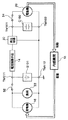
図2は、本発明の第2実施形態に係る蓄電装置を含む動力出力装置の構成の概略を示す図である。本実施形態においては、二次電池S101の電圧を昇圧して電気二重層キャパシタC100へ供給する昇圧回路30が電流制限手段14と電気二重層キャパシタC100との間に設けられている。昇圧回路30については、例えばDC−DCコンバータによって構成され、その出力電圧が電気二重層キャパシタC100の耐電圧を超えないように制御される。他の構成については第1実施形態と同様であるため説明を省略する。
(2) 2nd Embodiment FIG. 2: is a figure which shows the outline of a structure of the power output device containing the electrical storage apparatus which concerns on 2nd Embodiment of this invention. In the present embodiment, a
本実施形態においても、第1実施形態と同様に、大エネルギーを蓄積することができるとともに大電力を瞬時に取り出すことができ、かつ長寿命化を実現できる。さらに、本実施形態によれば、二次電池S101の電圧を昇圧して電気二重層キャパシタC100へ供給する昇圧回路30を設けることにより、電気二重層キャパシタC100の電圧を二次電池S101の電圧より高くすることができるので、電気二重層キャパシタC100に蓄積できる電気エネルギーを増大させることができる。さらに、内燃機関18を始動させるときに電気二重層キャパシタC100から電動機20へ流れる電流を低減させることができる。
Also in the present embodiment, as in the first embodiment, a large amount of energy can be accumulated, a large amount of electric power can be taken out instantaneously, and a long life can be realized. Furthermore, according to the present embodiment, by providing the
なお、上記の説明では、昇圧回路30が電流制限手段14と電気二重層キャパシタC100との間に設けられている場合について説明したが、昇圧回路30は二次電池S101と電流制限手段14との間に設けられていてもよい。
In the above description, the case where the
(3)第3実施形態
図3は、本発明の第3実施形態に係る蓄電装置の構成の概略を示す図である。図3においては、発電機16、内燃機関18、電動機20及び負荷22の図示を省略しているが、それらの構成については第1実施形態と同様である。本実施形態においては、充電用トランスT101、スイッチSW101〜SW106及びスイッチ制御回路B101がさらに備えられている。
(3) Third Embodiment FIG. 3 is a diagram schematically illustrating the configuration of a power storage device according to a third embodiment of the present invention. Although illustration of the
電気二重層キャパシタC101〜C106は互いに直列に接続されている。直列接続された電気二重層キャパシタの各々については、電気二重層キャパシタセル単体であってもよいし、複数の電気二重層キャパシタセルが並列接続されたものであってもよい。 Electric double layer capacitors C101 to C106 are connected in series with each other. Each of the electric double layer capacitors connected in series may be a single electric double layer capacitor cell or a plurality of electric double layer capacitor cells connected in parallel.
二次電池S101の両端子TM111,TM112間には、電流制限手段14を介して電気二重層キャパシタC104〜C106が接続されている。一方、電気二重層キャパシタC101〜C103については、二次電池S101の両端子TM111,TM112間に接続されていない。このように、電気二重層キャパシタC101〜C106は、二次電池S101の両端子TM111,TM112間に接続される電気二重層キャパシタC104〜C106、及び二次電池S101の両端子TM111,TM112間に接続されない電気二重層キャパシタC101〜C103によって構成されることになる。なお、電気二重層キャパシタC104〜C106全体の耐電圧が二次電池S101の定格電圧より高くなっている。
Electric double layer capacitors C104 to C106 are connected between the terminals TM111 and TM112 of the secondary battery S101 via the current limiting
充電用トランスT101は、充電用巻線L101〜L106及び回収用巻線L141を含んでいる。充電用巻線L101〜L106は、電気二重層キャパシタC101〜C106にそれぞれ対応して設けられており、電気二重層キャパシタC101〜C106の両端子間にそれぞれ接続されている。そして、充電用巻線L101〜L106は、互いに磁気的に結合されており、その巻数が略等しく設定されていることにより、電気二重層キャパシタC101〜C106の各々の両端子間に略同一の誘起電圧を印加可能となっている。 The charging transformer T101 includes charging windings L101 to L106 and a recovery winding L141. Charging windings L101 to L106 are provided corresponding to electric double layer capacitors C101 to C106, respectively, and are connected between both terminals of electric double layer capacitors C101 to C106. The charging windings L101 to L106 are magnetically coupled to each other, and the number of turns is set to be substantially equal, so that substantially the same induction is caused between both terminals of the electric double layer capacitors C101 to C106. A voltage can be applied.
回収用巻線L141は、電気二重層キャパシタC101〜C106の両端子TM101,TM102間に接続されている。回収用巻線L141の巻数と充電用巻線L101〜L106の巻数の比は、直列接続された電気二重層キャパシタの数に略等しく設定されている。そして、回収用巻線L141は、充電用巻線L101〜L106と磁気的に結合されていることにより、電気二重層キャパシタC101〜C106全体に誘起電圧を印加可能となっている。また、回収用巻線L141と電気二重層キャパシタC101との間には、回収用巻線L141から電気二重層キャパシタC101への電流の流れのみを許容する整流ダイオードCD101が設けられている。 The recovery winding L141 is connected between both terminals TM101 and TM102 of the electric double layer capacitors C101 to C106. The ratio of the number of windings of the recovery winding L141 and the number of windings of the charging windings L101 to L106 is set substantially equal to the number of electric double layer capacitors connected in series. The recovery winding L141 is magnetically coupled to the charging windings L101 to L106, so that an induced voltage can be applied to the entire electric double layer capacitors C101 to C106. Further, between the recovery winding L141 and the electric double layer capacitor C101, a rectifier diode CD101 that allows only a current flow from the recovery winding L141 to the electric double layer capacitor C101 is provided.
切換手段としてのスイッチSW101〜SW106は、キャパシタC101と巻線L101との間、キャパシタC102と巻線L102との間、キャパシタC103と巻線L103との間、キャパシタC104と巻線L104との間、キャパシタC105と巻線L105との間、及びキャパシタC106と巻線L106との間における導通/非導通の切り換えがそれぞれ可能である。スイッチSW101〜SW106の一例としては、FETを用いることができる。 The switches SW101 to SW106 as switching means are between the capacitor C101 and the winding L101, between the capacitor C102 and the winding L102, between the capacitor C103 and the winding L103, between the capacitor C104 and the winding L104, It is possible to switch between conduction / non-conduction between the capacitor C105 and the winding L105 and between the capacitor C106 and the winding L106. An FET can be used as an example of the switches SW101 to SW106.
制御手段としてのスイッチ制御回路B101は、スイッチSW101〜SW106の導通/非導通を同期させて交互に切り換える制御を行う。 The switch control circuit B101 serving as a control unit performs control to alternately switch the conduction / non-conduction of the switches SW101 to SW106 in synchronization.
なお、直列に接続する電気二重層キャパシタの数n1、及び二次電池S101の両端子TM111,TM112間に接続する電気二重層キャパシタの数n2については、n1>n2の条件で任意に設定することができる。 The number n1 of electric double layer capacitors connected in series and the number n2 of electric double layer capacitors connected between both terminals TM111 and TM112 of the secondary battery S101 should be arbitrarily set under the condition of n1> n2. Can do.
他の構成については第1実施形態と同様であるため説明を省略し、以下、本実施形態の動作について説明する。 Since the other configuration is the same as that of the first embodiment, the description thereof will be omitted, and the operation of the present embodiment will be described below.
電気二重層キャパシタC104〜C106には、二次電池S101からの電圧が印加される。一方、スイッチ制御回路B101は、スイッチSW101〜SW106の導通/非導通を同期させながら交互に切り換える制御を行う。 The voltage from the secondary battery S101 is applied to the electric double layer capacitors C104 to C106. On the other hand, the switch control circuit B101 performs control to switch alternately while synchronizing the conduction / non-conduction of the switches SW101 to SW106.
ここで、互いに磁気的に結合された充電用巻線L101〜L106の巻数は略等しいため、スイッチSW101〜SW106の導通時における充電用巻線L101〜L106に発生する誘起電圧は略同一となる。充電用巻線L101〜L106は電気二重層キャパシタC101〜C106の両端子間にそれぞれ接続されるため、充電用巻線L101〜L106に発生する誘起電圧は、ほぼ電気二重層キャパシタC101〜C106の平均電圧となり、スイッチSW101〜SW106の導通時には、この電圧が電気二重層キャパシタC101〜C106の各々に印加される。このように、電気二重層キャパシタC101〜C103については、二次電池S101の両端子TM111,TM112間に接続されていないものの、充電用巻線L101〜L103に発生する誘起電圧をそれぞれ印加することができるので、充電を行うことができる。 Here, since the number of turns of the charging windings L101 to L106 magnetically coupled to each other is substantially equal, the induced voltages generated in the charging windings L101 to L106 when the switches SW101 to SW106 are conductive are substantially the same. Since the charging windings L101 to L106 are respectively connected between both terminals of the electric double layer capacitors C101 to C106, the induced voltage generated in the charging windings L101 to L106 is almost the average of the electric double layer capacitors C101 to C106. When the switches SW101 to SW106 are turned on, this voltage is applied to each of the electric double layer capacitors C101 to C106. Thus, although the electric double layer capacitors C101 to C103 are not connected between the terminals TM111 and TM112 of the secondary battery S101, the induced voltages generated in the charging windings L101 to L103 can be applied, respectively. Since it can, it can charge.
スイッチSW101〜SW106の導通時に、電気二重層キャパシタC101〜C106の電圧にばらつきが発生している場合、誘起電圧より電圧の高いキャパシタについては該キャパシタの両端子間に接続された充電用巻線へ放電電流が流れ、誘起電圧より電圧の低いキャパシタについては該キャパシタの両端子間に接続された充電用巻線からの充電電流が流れる。したがって、各電気二重層キャパシタC101〜C106の電圧が均等になるように充電が行われる。 If the voltages of the electric double layer capacitors C101 to C106 vary when the switches SW101 to SW106 are turned on, the capacitor having a voltage higher than the induced voltage is connected to the charging winding connected between both terminals of the capacitor. A discharge current flows, and for a capacitor whose voltage is lower than the induced voltage, a charging current flows from a charging winding connected between both terminals of the capacitor. Therefore, charging is performed so that the voltages of the electric double layer capacitors C101 to C106 are equal.
スイッチSW101〜SW106の非導通時には、充電用トランスT101に蓄えられた磁気エネルギーにより、回収用巻線L141に誘起電圧が発生する。この電圧が電気二重層キャパシタC101〜C106全体に印加され、充電電流が整流ダイオードCD101を介して電気二重層キャパシタC101〜C106へ流れることにより、エネルギー回収が行われ、電気二重層キャパシタC101〜C106全体の充電が行われる。このように、二次電池S101の両端子TM111,TM112間に接続されていない電気二重層キャパシタC101〜C103については、回収用巻線L141によっても充電が行われる。なお、他の動作については第1実施形態と同様であるため説明を省略する。 When the switches SW101 to SW106 are non-conductive, an induced voltage is generated in the recovery winding L141 by the magnetic energy stored in the charging transformer T101. This voltage is applied to the entire electric double layer capacitors C101 to C106, and the charging current flows to the electric double layer capacitors C101 to C106 via the rectifier diode CD101, whereby energy recovery is performed, and the entire electric double layer capacitors C101 to C106. Is charged. As described above, the electric double layer capacitors C101 to C103 that are not connected between the terminals TM111 and TM112 of the secondary battery S101 are also charged by the recovery winding L141. Since other operations are the same as those in the first embodiment, description thereof is omitted.
本実施形態においても、第1実施形態と同様に、大エネルギーを蓄積することができるとともに大電力を瞬時に取り出すことができ、かつ長寿命化を実現できる。さらに、本実施形態によれば、充電用トランスT101の充電用巻線L101〜L106により各電気二重層キャパシタC101〜C106の両端子間に略同一の誘起電圧を印加することができるので、各電気二重層キャパシタC101〜C106の電圧が均等になるように充電を行うことができる。したがって、電気二重層キャパシタC101〜C106に効率よく電気エネルギーを蓄積することができる。 Also in the present embodiment, as in the first embodiment, a large amount of energy can be accumulated, a large amount of electric power can be taken out instantaneously, and a long life can be realized. Furthermore, according to the present embodiment, substantially the same induced voltage can be applied between both terminals of the electric double layer capacitors C101 to C106 by the charging windings L101 to L106 of the charging transformer T101. Charging can be performed so that the voltages of the double layer capacitors C101 to C106 are equal. Therefore, electric energy can be efficiently stored in the electric double layer capacitors C101 to C106.
さらに、電気二重層キャパシタC101〜C103については、二次電池S101の両端子TM111,TM112間に接続されていなくても充電用巻線L101〜L103に発生する誘起電圧がそれぞれ印加されることにより充電を行うことができるので、二次電池S101からの電圧を昇圧させて電気二重層キャパシタC101〜C106を充電することができ、電気二重層キャパシタC101〜C106全体の充電電圧は二次電池S101の出力電圧よりも高くなる。したがって、二次電池S101の出力電圧を増加させることなく、電気二重層キャパシタ全体の充電電圧を増大させることができるので、内燃機関18を始動させるときに電気二重層キャパシタC100から電動機20へ流れる電流を低減させることができる。また、二次電池S101からの電圧を昇圧させて電気二重層キャパシタC101〜C106の充電を行う際に、例えばDC−DCコンバータのような昇圧用の回路を用いる必要がないため、装置の小型化を実現できる。
Furthermore, the electric double layer capacitors C101 to C103 are charged by applying the induced voltages generated in the charging windings L101 to L103 even if they are not connected between the terminals TM111 and TM112 of the secondary battery S101. Therefore, the voltage from the secondary battery S101 can be boosted to charge the electric double layer capacitors C101 to C106. The charging voltage of the electric double layer capacitors C101 to C106 as a whole is the output of the secondary battery S101. It becomes higher than the voltage. Therefore, since the charging voltage of the entire electric double layer capacitor can be increased without increasing the output voltage of the secondary battery S101, the current flowing from the electric double layer capacitor C100 to the
(4)第4実施形態
図4は、本発明の第4実施形態に係る蓄電装置の構成の概略を示す図である。図4においても、発電機16、内燃機関18、電動機20及び負荷22の図示を省略しているが、それらの構成については第1実施形態と同様である。本実施形態における充電用トランスT101は、互いに磁気的に結合された中点タップ付き巻線L151〜L153を含んでいる。
(4) 4th Embodiment FIG. 4: is a figure which shows the outline of a structure of the electrical storage apparatus which concerns on 4th Embodiment of this invention. Also in FIG. 4, the
中点タップ付き巻線L151については、その中点が電気二重層キャパシタC101と電気二重層キャパシタC102との間に接続され、その両端子が電気二重層キャパシタC101,C102の両端子と接続される。ただし、中点タップ付き巻線L151の電気二重層キャパシタC101,C102の正負端子に対する接続方向がスイッチSW101,SW102によって切り換え可能である。具体的には、スイッチSW101,SW102は、電気二重層キャパシタC101の正側端子と中点タップ付き巻線L151の一端子とを接続し、電気二重層キャパシタC102の負側端子と中点タップ付き巻線L151の他端子とを接続する第1の状態(図4に示す状態)と、電気二重層キャパシタC101の正側端子と中点タップ付き巻線L151の他端子とを接続し、電気二重層キャパシタC102の負側端子と中点タップ付き巻線L151の一端子とを接続する第2の状態と、の切り換えが可能である。 As for winding L151 with a midpoint tap, the midpoint is connected between electric double layer capacitor C101 and electric double layer capacitor C102, and both terminals thereof are connected to both terminals of electric double layer capacitors C101 and C102. . However, the connection direction of the winding L151 with the midpoint tap to the positive and negative terminals of the electric double layer capacitors C101 and C102 can be switched by the switches SW101 and SW102. Specifically, the switches SW101 and SW102 connect the positive side terminal of the electric double layer capacitor C101 and one terminal of the winding L151 with a midpoint tap, and the negative side terminal of the electric double layer capacitor C102 and the midpoint tap. The first state (the state shown in FIG. 4) in which the other terminal of the winding L151 is connected, the positive terminal of the electric double layer capacitor C101, and the other terminal of the winding L151 with a mid-point tap are connected. It is possible to switch between the second state in which the negative terminal of the multilayer capacitor C102 and one terminal of the winding L151 with the midpoint tap are connected.
同様に、中点タップ付き巻線L152については、その中点が電気二重層キャパシタC103と電気二重層キャパシタC104との間に接続され、その両端子が電気二重層キャパシタC103,C104の両端子と接続される。スイッチSW103,SW104は、電気二重層キャパシタC103の正側端子と中点タップ付き巻線L152の一端子とを接続し、電気二重層キャパシタC104の負側端子と中点タップ付き巻線L152の他端子とを接続する第1の状態(図4に示す状態)と、電気二重層キャパシタC103の正側端子と中点タップ付き巻線L152の他端子とを接続し、電気二重層キャパシタC104の負側端子と中点タップ付き巻線L152の一端子とを接続する第2の状態と、の切り換えが可能である。そして、中点タップ付き巻線L153については、その中点が電気二重層キャパシタC105と電気二重層キャパシタC106との間に接続され、その両端子が電気二重層キャパシタC105,C106の両端子と接続される。スイッチSW105,SW106は、電気二重層キャパシタC105の正側端子と中点タップ付き巻線L153の一端子とを接続し、電気二重層キャパシタC106の負側端子と中点タップ付き巻線L153の他端子とを接続する第1の状態(図4に示す状態)と、電気二重層キャパシタC105の正側端子と中点タップ付き巻線L153の他端子とを接続し、電気二重層キャパシタC106の負側端子と中点タップ付き巻線L153の一端子とを接続する第2の状態と、の切り換えが可能である。 Similarly, for the winding L152 with a midpoint tap, the midpoint is connected between the electric double layer capacitor C103 and the electric double layer capacitor C104, and both terminals thereof are connected to both terminals of the electric double layer capacitors C103 and C104. Connected. The switches SW103 and SW104 connect the positive side terminal of the electric double layer capacitor C103 and one terminal of the midpoint tapped winding L152, and the other side of the negative side terminal of the electric double layer capacitor C104 and the midpoint tapped winding L152. The first state of connecting the terminals (the state shown in FIG. 4), the positive side terminal of the electric double layer capacitor C103 and the other terminal of the winding L152 with a midpoint tap are connected, and the negative of the electric double layer capacitor C104 is connected. It is possible to switch between the second state in which the side terminal and one terminal of the winding L152 with the midpoint tap are connected. And about the winding L153 with a midpoint tap, the midpoint is connected between the electric double layer capacitor C105 and the electric double layer capacitor C106, and both terminals thereof are connected to both terminals of the electric double layer capacitors C105 and C106. Is done. The switches SW105 and SW106 connect the positive side terminal of the electric double layer capacitor C105 and one terminal of the midpoint tapped winding L153, and other than the negative side terminal of the electric double layer capacitor C106 and the midpoint tapped winding L153. The first state of connecting the terminals (the state shown in FIG. 4), the positive side terminal of the electric double layer capacitor C105 and the other terminal of the winding L153 with a midpoint tap are connected, and the negative state of the electric double layer capacitor C106 is connected. It is possible to switch between the second state in which the side terminal and one terminal of the winding L153 with a midpoint tap are connected.
このように、本実施形態においては、電気二重層キャパシタC101,C102に誘起電圧を印加するための充電用巻線L101,L102が中点タップ付き巻線L151によって構成されている。同様に、電気二重層キャパシタC103,C104に誘起電圧を印加するための充電用巻線L103,L104が中点タップ付き巻線L152によって構成され、電気二重層キャパシタC105,C106に誘起電圧を印加するための充電用巻線L105,L106が中点タップ付き巻線L153によって構成されている。そして、上記に説明したスイッチSW101,SW102の第1の状態と第2の状態とを交互に切り換えることで、充電用巻線L101,L102の電気二重層キャパシタC101,C102の正負端子に対する接続方向の切り換えが可能である。同様に、スイッチSW103,SW104の第1の状態と第2の状態とを交互に切り換えることで、充電用巻線L103,L104の電気二重層キャパシタC103,C104の正負端子に対する接続方向の切り換えが可能であり、スイッチSW105,SW106の第1の状態と第2の状態とを交互に切り換えることで、充電用巻線L105,L106の電気二重層キャパシタC105,C106の正負端子に対する接続方向の切り換えが可能である。 As described above, in this embodiment, the charging windings L101 and L102 for applying the induced voltage to the electric double layer capacitors C101 and C102 are constituted by the winding L151 with a midpoint tap. Similarly, the charging windings L103 and L104 for applying an induced voltage to the electric double layer capacitors C103 and C104 are constituted by a midpoint tapped winding L152, and the induced voltage is applied to the electric double layer capacitors C105 and C106. Charging windings L105 and L106 for this purpose are constituted by a winding L153 with a midpoint tap. Then, by alternately switching between the first state and the second state of the switches SW101 and SW102 described above, the charging windings L101 and L102 are connected in the direction of connection to the positive and negative terminals of the electric double layer capacitors C101 and C102. Switching is possible. Similarly, by alternately switching between the first state and the second state of the switches SW103 and SW104, the connection direction of the charging windings L103 and L104 with respect to the positive and negative terminals of the electric double layer capacitors C103 and C104 can be switched. By alternately switching the first state and the second state of the switches SW105 and SW106, the connection direction of the charging windings L105 and L106 with respect to the positive and negative terminals of the electric double layer capacitors C105 and C106 can be switched. It is.
スイッチ制御回路B101は、上記に説明したスイッチSW101〜SW106の第1の状態と第2の状態とをそれらの状態の時間配分が略等しくなるように同期させながら交互に切り換える制御を行う。 The switch control circuit B101 performs control to alternately switch the first state and the second state of the switches SW101 to SW106 described above while synchronizing the time distributions of these states to be substantially equal.
他の構成については第3実施形態と同様であるため説明を省略し、以下、本実施形態の動作について説明する。 Since the other configuration is the same as that of the third embodiment, the description thereof is omitted, and the operation of the present embodiment will be described below.
電気二重層キャパシタC104〜C106には、二次電池S101からの電圧が印加される。一方、スイッチ制御回路B101は、上記に説明したスイッチSW101〜SW106の第1の状態と第2の状態とを同期させながら交互に切り換える制御を行う。 The voltage from the secondary battery S101 is applied to the electric double layer capacitors C104 to C106. On the other hand, the switch control circuit B101 performs control to switch alternately while synchronizing the first state and the second state of the switches SW101 to SW106 described above.
ここで、互いに磁気的に結合された充電用巻線L101〜L106の巻数は略等しいため、スイッチSW101〜SW106の第1の状態時において充電用巻線L101〜L106に発生する誘起電圧は略同一となる。充電用巻線L101〜L106は電気二重層キャパシタC101〜C106の両端子間にそれぞれ接続されるため、充電用巻線L101〜L106に発生する誘起電圧は、ほぼ電気二重層キャパシタC101〜C106の平均電圧となり、スイッチSW101〜SW106の第1の状態時に、この電圧が電気二重層キャパシタC101〜C106の各々に印加される。 Here, since the number of turns of the charging windings L101 to L106 magnetically coupled to each other is substantially equal, the induced voltages generated in the charging windings L101 to L106 when the switches SW101 to SW106 are in the first state are substantially the same. It becomes. Since the charging windings L101 to L106 are respectively connected between both terminals of the electric double layer capacitors C101 to C106, the induced voltage generated in the charging windings L101 to L106 is almost the average of the electric double layer capacitors C101 to C106. This voltage is applied to each of the electric double layer capacitors C101 to C106 when the switches SW101 to SW106 are in the first state.
本実施形態においては、スイッチSW101〜SW106を第2の状態に切り換えても、ほぼ電気二重層キャパシタC101〜C106の平均電圧となる誘起電圧が充電用巻線L101〜L106の各々に発生し、この電圧が電気二重層キャパシタC101〜C106の各々に印加される。 In this embodiment, even if the switches SW101 to SW106 are switched to the second state, an induced voltage that is substantially the average voltage of the electric double layer capacitors C101 to C106 is generated in each of the charging windings L101 to L106. A voltage is applied to each of the electric double layer capacitors C101 to C106.
第1実施形態と同様に、電気二重層キャパシタC101〜C106の電圧にばらつきが発生している場合、誘起電圧より電圧の高いキャパシタについては該キャパシタの両端子間に接続された充電用巻線へ放電電流が流れ、誘起電圧より電圧の低いキャパシタについては該キャパシタの両端子間に接続された充電用巻線からの充電電流が流れる。したがって、各電気二重層キャパシタC101〜C106の電圧が均等になるように充電が行われる。また、電気二重層キャパシタC101〜C103については、二次電池S101の両端子TM111,TM112間に接続されていないものの、充電用巻線L101〜L103に発生する誘起電圧をそれぞれ印加することができるので、充電を行うことができる。なお、他の動作については第3実施形態と同様であるため説明を省略する。 As in the first embodiment, when variations occur in the voltages of the electric double layer capacitors C101 to C106, the capacitor having a voltage higher than the induced voltage is connected to the charging winding connected between both terminals of the capacitor. A discharge current flows, and for a capacitor whose voltage is lower than the induced voltage, a charging current flows from a charging winding connected between both terminals of the capacitor. Therefore, charging is performed so that the voltages of the electric double layer capacitors C101 to C106 are equal. Further, although the electric double layer capacitors C101 to C103 are not connected between the terminals TM111 and TM112 of the secondary battery S101, the induced voltages generated in the charging windings L101 to L103 can be applied, respectively. Can be charged. Since other operations are the same as those in the third embodiment, description thereof is omitted.
本実施形態においても、第3実施形態と同様に、各電気二重層キャパシタC101〜C106の電圧が均等になるように充電を行うことができるとともに、例えばDC−DCコンバータのような昇圧用の回路を用いることなく二次電池S101からの電圧を昇圧させて電気二重層キャパシタC101〜C106を充電することができる。 In the present embodiment, similarly to the third embodiment, charging can be performed so that the voltages of the electric double layer capacitors C101 to C106 are equal, and a boosting circuit such as a DC-DC converter is used. The electric double layer capacitors C101 to C106 can be charged by boosting the voltage from the secondary battery S101 without using.
さらに、本実施形態においては、電気二重層キャパシタC101〜C106と充電用巻線L101〜L106との接続動作はプッシュプル動作となるため、電圧のばらつきを補正するための誘起電圧を常に印加することが可能となり、均等充電動作を効率よく行うことができる。また、充電用トランスT101に蓄えられた磁気エネルギーは逆の半サイクルで電気二重層キャパシタC101〜C106へ回収可能なため、第3実施形態における回収用巻線L141及び整流ダイオードCD101を省略することができる。 Furthermore, in this embodiment, since the connection operation between the electric double layer capacitors C101 to C106 and the charging windings L101 to L106 is a push-pull operation, an induced voltage for correcting the voltage variation is always applied. Thus, the uniform charging operation can be performed efficiently. Further, since the magnetic energy stored in the charging transformer T101 can be recovered to the electric double layer capacitors C101 to C106 in the reverse half cycle, the recovery winding L141 and the rectifier diode CD101 in the third embodiment may be omitted. it can.
(5)第5実施形態
図5は、本発明の第5実施形態に係る蓄電装置の構成の概略を示す図である。図5においても、発電機16、内燃機関18、電動機20及び負荷22の図示を省略しているが、それらの構成については第1実施形態と同様である。本実施形態においては、電気二重層キャパシタC101〜C118が直列接続され、二次電池S101の両端子TM111,TM112間に電流制限手段14を介して電気二重層キャパシタC113〜C118が接続されている。そして、充電用トランスT101が3つのトランスT111,T112,T113に分割されて設けられている。トランスT111,T112,T113は巻線L171,L172,L173をそれぞれ含んでいる。巻線L171は充電用巻線L101〜L106と磁気的に結合され、巻線L172は充電用巻線L107〜L112と磁気的に結合され、巻線L173は充電用巻線L113〜L118と磁気的に結合されている。また、巻線L171,L172,L173は互いに並列接続されていることにより、トランスT111,T112,T113間の電気的接続が行われている。他の構成は第4実施形態と同様であるため説明を省略する。
(5) Fifth Embodiment FIG. 5 is a diagram schematically illustrating the configuration of a power storage device according to a fifth embodiment of the present invention. Also in FIG. 5, the
なお、図5では充電用トランスT101を3つに分割した例を示しているが、充電用トランスT101の分割数については任意に設定することができる。また、第3実施形態においても、充電用トランスT101を複数に分割して設けることができる。 Although FIG. 5 shows an example in which the charging transformer T101 is divided into three, the number of divisions of the charging transformer T101 can be arbitrarily set. Also in the third embodiment, the charging transformer T101 can be divided into a plurality of parts.
ここで、直列接続される電気二重層キャパシタの数が多くなるにつれて、1つに共有化された充電用トランスT101では充電用巻線の巻数の確保が難しくなる。しかし、本実施形態によれば、多数の電気二重層キャパシタを直列接続することができ、全体の耐電圧をさらに増加させることができ、負荷である電動機20への放電電流をさらに減少させることができる。
Here, as the number of electric double layer capacitors connected in series increases, it becomes difficult to secure the number of turns of the charging winding in the charging transformer T101 shared by one. However, according to this embodiment, a large number of electric double layer capacitors can be connected in series, the overall withstand voltage can be further increased, and the discharge current to the
さらに、充電用トランスT101を分割したときのトランス間の電気的接続については、電気二重層キャパシタの両端子間を介して接続してもよい。その一例として、トランスT111とトランスT112とを電気二重層キャパシタC106,C107の両端子間を介して接続した場合を図6に示す。図6においても、発電機16、内燃機関18、電動機20及び負荷22の図示を省略しているが、それらの構成については第1実施形態と同様である。
Furthermore, the electrical connection between the transformers when the charging transformer T101 is divided may be connected via both terminals of the electric double layer capacitor. As an example, FIG. 6 shows a case where the transformer T111 and the transformer T112 are connected via both terminals of the electric double layer capacitors C106 and C107. Also in FIG. 6, the
図6に示す構成においては、電気二重層キャパシタC101〜C112が直列接続され、二次電池S101の両端子TM111,TM112間に電気二重層キャパシタC107〜C112が接続されている。そして、トランスT111は中点タップ付き巻線L151〜L153と磁気的に結合された中点タップ付き巻線L161をさらに含み、トランスT112は中点タップ付き巻線L154〜L156と磁気的に結合された中点タップ付き巻線L162をさらに含む。 In the configuration shown in FIG. 6, electric double layer capacitors C101 to C112 are connected in series, and electric double layer capacitors C107 to C112 are connected between both terminals TM111 and TM112 of the secondary battery S101. The transformer T111 further includes a midpoint tapped winding L161 magnetically coupled to the midpoint tapped windings L151 to L153, and the transformer T112 is magnetically coupled to the midpoint tapped windings L154 to L156. Furthermore, a winding L162 with a midpoint tap is further included.
中点タップ付き巻線L161については、その中点が電気二重層キャパシタC107の負側端子に接続され、その両端子のいずれかがスイッチSW121を介して電気二重層キャパシタC107の正側端子に接続される。スイッチSW121は、電気二重層キャパシタC107の正側端子と中点タップ付き巻線L161の一端子とを接続する第1の状態(図6に示す状態)と、電気二重層キャパシタC107の正側端子と中点タップ付き巻線L161の他端子とを接続する第2の状態と、の切り換えが可能である。 As for winding L161 with a midpoint tap, its midpoint is connected to the negative side terminal of electric double layer capacitor C107, and either one of the two terminals is connected to the positive side terminal of electric double layer capacitor C107 via switch SW121. Is done. Switch SW121 includes a first state (state shown in FIG. 6) for connecting the positive side terminal of electric double layer capacitor C107 and one terminal of winding L161 with a midpoint tap, and the positive side terminal of electric double layer capacitor C107. And a second state in which the other terminal of the winding L161 with the midpoint tap is connected can be switched.
同様に、中点タップ付き巻線L162については、その中点が電気二重層キャパシタC106の正側端子に接続され、その両端子のいずれかがスイッチSW124を介して電気二重層キャパシタC106の負側端子に接続される。スイッチSW124は、電気二重層キャパシタC106の負側端子と中点タップ付き巻線L162の他端子とを接続する第1の状態(図6に示す状態)と、電気二重層キャパシタC106の負側端子と中点タップ付き巻線L162の一端子とを接続する第2の状態と、の切り換えが可能である。 Similarly, the midpoint tapped winding L162 has its midpoint connected to the positive terminal of the electric double layer capacitor C106, and either of the two terminals is connected to the negative side of the electric double layer capacitor C106 via the switch SW124. Connected to the terminal. Switch SW124 has a first state (state shown in FIG. 6) for connecting the negative terminal of electric double layer capacitor C106 and the other terminal of winding L162 with a midpoint tap, and a negative terminal of electric double layer capacitor C106. And a second state in which one terminal of the winding L162 with a midpoint tap is connected.
スイッチSW121,SW124が第1の状態(図6に示す状態)のときは、トランスT111の充電用巻線L121とトランスT112の充電用巻線L107とが電気二重層キャパシタC107の両端子間を介して接続され、トランスT111の充電用巻線L106とトランスT112の充電用巻線L124とが電気二重層キャパシタC106の両端子間を介して接続される。一方、スイッチSW121,SW124が第2の状態のときは、トランスT111の充電用巻線L122とトランスT112の充電用巻線L108とが電気二重層キャパシタC107の両端子間を介して接続され、トランスT111の充電用巻線L105とトランスT112の充電用巻線L123とが電気二重層キャパシタC106の両端子間を介して接続される。 When the switches SW121 and SW124 are in the first state (the state shown in FIG. 6), the charging winding L121 of the transformer T111 and the charging winding L107 of the transformer T112 are interposed between both terminals of the electric double layer capacitor C107. The charging winding L106 of the transformer T111 and the charging winding L124 of the transformer T112 are connected via both terminals of the electric double layer capacitor C106. On the other hand, when the switches SW121 and SW124 are in the second state, the charging winding L122 of the transformer T111 and the charging winding L108 of the transformer T112 are connected via both terminals of the electric double layer capacitor C107. The charging winding L105 of T111 and the charging winding L123 of the transformer T112 are connected via both terminals of the electric double layer capacitor C106.
図6において、電圧のばらつきの一例として、電気二重層キャパシタC101の電圧が誘起電圧より高く、電気二重層キャパシタC112の電圧が誘起電圧より低い場合を考える。この場合、電気二重層キャパシタC112はトランスT112を介して電気二重層キャパシタC106〜C111から充電電流を受ける。一方、電気二重層キャパシタC101はトランスT111を介して電気二重層キャパシタC102〜C107へ充電電流を流す。したがって、電気二重層キャパシタC101から電気二重層キャパシタC106,C107を介して電気二重層キャパシタC112へ充電電流が流れることになり、電圧が均等になるように充電が行われる。 In FIG. 6, as an example of voltage variation, a case where the voltage of the electric double layer capacitor C101 is higher than the induced voltage and the voltage of the electric double layer capacitor C112 is lower than the induced voltage is considered. In this case, the electric double layer capacitor C112 receives a charging current from the electric double layer capacitors C106 to C111 via the transformer T112. On the other hand, the electric double layer capacitor C101 allows a charging current to flow to the electric double layer capacitors C102 to C107 via the transformer T111. Therefore, a charging current flows from the electric double layer capacitor C101 to the electric double layer capacitor C112 via the electric double layer capacitors C106 and C107, and charging is performed so that the voltages are equalized.
そして、トランスT114がさらに備えられている場合を図7に示す。図7に示す構成においては、トランスT111とトランスT114とが電気二重層キャパシタC101〜C104の両端子間のそれぞれを介して接続されており、トランスT112とトランスT114とが電気二重層キャパシタC109〜C112の両端子間のそれぞれを介して接続されている。図7に示す構成によれば、電圧のばらつきを補正するための充電経路が多重化されるので、電気二重層キャパシタへ流す電流を増大させることができ、充電時間を短縮することができる。 FIG. 7 shows a case where a transformer T114 is further provided. In the configuration shown in FIG. 7, the transformer T111 and the transformer T114 are connected to each other between both terminals of the electric double layer capacitors C101 to C104, and the transformer T112 and the transformer T114 are connected to the electric double layer capacitors C109 to C112. Are connected via each of the two terminals. According to the configuration shown in FIG. 7, since the charging paths for correcting the voltage variation are multiplexed, the current flowing to the electric double layer capacitor can be increased and the charging time can be shortened.
以上、本発明の実施の形態について説明したが、本発明はこうした実施の形態に何等限定されるものではなく、本発明の技術思想を逸脱しない範囲内において、種々なる形態で実施し得ることは勿論である。 As mentioned above, although embodiment of this invention was described, this invention is not limited to such embodiment at all, and within the range which does not deviate from the technical idea of this invention, it can implement with a various form. Of course.
14 電流制限手段、16 発電機、18 内燃機関、20 電動機、30 昇圧回路、B101 スイッチ制御回路、C100〜C118 電気二重層キャパシタ、S101 二次電池、SW101〜SW118 スイッチ、T101 充電用トランス。 14 current limiting means, 16 generator, 18 internal combustion engine, 20 motor, 30 booster circuit, B101 switch control circuit, C100 to C118 electric double layer capacitor, S101 secondary battery, SW101 to SW118 switch, T101 transformer for charging.
Claims (3)
直列に接続された複数の電気二重層キャパシタと、
該複数の電気二重層キャパシタの充電を行うことが可能な二次電池と、
各電気二重層キャパシタの両端子間を磁気的に結合し、各電気二重層キャパシタの両端子間に略同一の誘起電圧を印加可能な充電用トランスと、
該誘起電圧が各電気二重層キャパシタの両端子間に印加されるように、各電気二重層キャパシタと充電用トランスとの間の接続状態を切り換え可能な切換手段と、
各電気二重層キャパシタと充電用トランスとの間の接続状態の切り換え制御を行う制御手段と、
を備え、
複数の電気二重層キャパシタは、二次電池の両端子間に接続された電気二重層キャパシタ及び二次電池の両端子間に接続されない電気二重層キャパシタによって構成され、
二次電池を用いて複数の電気二重層キャパシタの充電を行う場合に、二次電池の両端子間に接続されない電気二重層キャパシタについては、前記制御手段により各電気二重層キャパシタと充電用トランスとの間の接続状態を切り換えることで、充電用トランスに発生する誘起電圧が印加されて充電が行われ、複数の電気二重層キャパシタ全体の充電電圧は二次電池の電圧より大きくなり、
前記第1の負荷を駆動するための電力は二次電池から供給され、前記第2の負荷を駆動するための電力は複数の電気二重層キャパシタから供給されることを特徴とする蓄電装置。 A power storage device capable of supplying electric power for driving a first load and a second load having a driving frequency lower than that of the first load and a large power consumption during driving,
A plurality of electric double layer capacitors connected in series ;
A secondary battery capable of charging of said plurality of electric double layer capacitor,
A charging transformer that magnetically couples both terminals of each electric double layer capacitor and can apply substantially the same induced voltage between both terminals of each electric double layer capacitor;
Switching means capable of switching a connection state between each electric double layer capacitor and the charging transformer so that the induced voltage is applied between both terminals of each electric double layer capacitor;
Control means for performing switching control of the connection state between each electric double layer capacitor and the charging transformer;
With
The plurality of electric double layer capacitors are constituted by an electric double layer capacitor connected between both terminals of the secondary battery and an electric double layer capacitor not connected between both terminals of the secondary battery,
When charging a plurality of electric double layer capacitors using a secondary battery, for the electric double layer capacitors that are not connected between both terminals of the secondary battery, each electric double layer capacitor, charging transformer, By switching the connection state between, the induced voltage generated in the charging transformer is applied and charging is performed, and the charging voltage of the plurality of electric double layer capacitors is larger than the voltage of the secondary battery,
A power storage device, wherein power for driving the first load is supplied from a secondary battery, and power for driving the second load is supplied from a plurality of electric double layer capacitors.
前記二次電池と該二次電池の両端子間に接続された電気二重層キャパシタとの間に流れる電流を制限するための電流制限手段を備えることを特徴とする蓄電装置。 The power storage device according to claim 1 ,
A power storage device comprising current limiting means for limiting a current flowing between the secondary battery and an electric double layer capacitor connected between both terminals of the secondary battery .
前記充電用トランスは複数のトランスに分割されて設けられており、
それらのトランス間が電気二重層キャパシタの両端子間を介して接続されていることを特徴とする蓄電装置。 The power storage device according to claim 1 or 2,
The charging transformer is divided into a plurality of transformers,
A power storage device characterized in that the transformers are connected through both terminals of the electric double layer capacitor .
Priority Applications (1)
| Application Number | Priority Date | Filing Date | Title |
|---|---|---|---|
| JP2003310594A JP4170177B2 (en) | 2003-09-02 | 2003-09-02 | Power storage device |
Applications Claiming Priority (1)
| Application Number | Priority Date | Filing Date | Title |
|---|---|---|---|
| JP2003310594A JP4170177B2 (en) | 2003-09-02 | 2003-09-02 | Power storage device |
Publications (2)
| Publication Number | Publication Date |
|---|---|
| JP2005080466A JP2005080466A (en) | 2005-03-24 |
| JP4170177B2 true JP4170177B2 (en) | 2008-10-22 |
Family
ID=34412422
Family Applications (1)
| Application Number | Title | Priority Date | Filing Date |
|---|---|---|---|
| JP2003310594A Expired - Fee Related JP4170177B2 (en) | 2003-09-02 | 2003-09-02 | Power storage device |
Country Status (1)
| Country | Link |
|---|---|
| JP (1) | JP4170177B2 (en) |
Cited By (1)
| Publication number | Priority date | Publication date | Assignee | Title |
|---|---|---|---|---|
| WO2019172789A1 (en) | 2018-02-14 | 2019-09-12 | Vers Produkcja Sp. Z O.O. Sp. K. | A method of charging and discharging capacitors in a vehicle with a combustion engine and system thereof |
Families Citing this family (5)
| Publication number | Priority date | Publication date | Assignee | Title |
|---|---|---|---|---|
| JP2009171694A (en) | 2008-01-15 | 2009-07-30 | Nisshinbo Holdings Inc | Charger |
| JP2009247145A (en) * | 2008-03-31 | 2009-10-22 | Japan Aerospace Exploration Agency | Power system |
| JP5707946B2 (en) * | 2011-01-11 | 2015-04-30 | カシオ計算機株式会社 | Power supply device and electronic timepiece |
| JP5861345B2 (en) * | 2011-09-15 | 2016-02-16 | 株式会社オートネットワーク技術研究所 | Auxiliary power supply for vehicle |
| US10491023B2 (en) * | 2017-12-30 | 2019-11-26 | Texas Instruments Incorporated | Capacitor balanced driver circuit for dual input charger |
-
2003
- 2003-09-02 JP JP2003310594A patent/JP4170177B2/en not_active Expired - Fee Related
Cited By (1)
| Publication number | Priority date | Publication date | Assignee | Title |
|---|---|---|---|---|
| WO2019172789A1 (en) | 2018-02-14 | 2019-09-12 | Vers Produkcja Sp. Z O.O. Sp. K. | A method of charging and discharging capacitors in a vehicle with a combustion engine and system thereof |
Also Published As
| Publication number | Publication date |
|---|---|
| JP2005080466A (en) | 2005-03-24 |
Similar Documents
| Publication | Publication Date | Title |
|---|---|---|
| KR101266733B1 (en) | Generator motor driving device and method for discharging capacitor of generator motor driving device | |
| JP4441920B2 (en) | Power supply | |
| JP5099012B2 (en) | DC / DC converter | |
| JP2009171694A (en) | Charger | |
| JP2006280110A (en) | Battery charging system for hybrid electric vehicle | |
| JPH05166593A (en) | Inductor voltage step-up converter with tap for operating gas discharge lamp | |
| JP4170177B2 (en) | Power storage device | |
| JP4468708B2 (en) | Power supply | |
| JP2012001159A (en) | Vehicle power source controller | |
| JP4923831B2 (en) | Power supply | |
| US6469476B1 (en) | Multi-mode converter for a motor vehicle electrical system | |
| JP5188962B2 (en) | Discharge lamp lighting device | |
| JP4075836B2 (en) | Vehicle power supply | |
| JP2010022133A (en) | Charger device | |
| WO2020059645A1 (en) | Power supply control device and power supply device | |
| JP2015149801A (en) | Battery control apparatus and control method | |
| JP2005080470A (en) | Capacitor device | |
| JP3854592B2 (en) | Charger charging device | |
| JP4139290B2 (en) | Electric vehicle power supply | |
| JP2010068650A (en) | Power system | |
| EP3782841B1 (en) | System of increasing temperature of battery for vehicle | |
| JP2000050404A (en) | Power source unit for hybrid electric automobile | |
| GB2565091A (en) | Multiple output battery system with alternator architectures | |
| JP2013240177A (en) | Vehicular power system | |
| KR101544024B1 (en) | electric charge and discharge of battery with two capacitor |
Legal Events
| Date | Code | Title | Description |
|---|---|---|---|
| A621 | Written request for application examination |
Free format text: JAPANESE INTERMEDIATE CODE: A621 Effective date: 20060720 |
|
| A977 | Report on retrieval |
Free format text: JAPANESE INTERMEDIATE CODE: A971007 Effective date: 20070709 |
|
| A131 | Notification of reasons for refusal |
Free format text: JAPANESE INTERMEDIATE CODE: A131 Effective date: 20070717 |
|
| A521 | Written amendment |
Free format text: JAPANESE INTERMEDIATE CODE: A523 Effective date: 20070918 |
|
| A02 | Decision of refusal |
Free format text: JAPANESE INTERMEDIATE CODE: A02 Effective date: 20080304 |
|
| A521 | Written amendment |
Free format text: JAPANESE INTERMEDIATE CODE: A523 Effective date: 20080403 |
|
| A911 | Transfer of reconsideration by examiner before appeal (zenchi) |
Free format text: JAPANESE INTERMEDIATE CODE: A911 Effective date: 20080508 |
|
| TRDD | Decision of grant or rejection written | ||
| A01 | Written decision to grant a patent or to grant a registration (utility model) |
Free format text: JAPANESE INTERMEDIATE CODE: A01 Effective date: 20080715 |
|
| A01 | Written decision to grant a patent or to grant a registration (utility model) |
Free format text: JAPANESE INTERMEDIATE CODE: A01 |
|
| A61 | First payment of annual fees (during grant procedure) |
Free format text: JAPANESE INTERMEDIATE CODE: A61 Effective date: 20080806 |
|
| FPAY | Renewal fee payment (event date is renewal date of database) |
Free format text: PAYMENT UNTIL: 20110815 Year of fee payment: 3 |
|
| R150 | Certificate of patent or registration of utility model |
Free format text: JAPANESE INTERMEDIATE CODE: R150 |
|
| FPAY | Renewal fee payment (event date is renewal date of database) |
Free format text: PAYMENT UNTIL: 20110815 Year of fee payment: 3 |
|
| S533 | Written request for registration of change of name |
Free format text: JAPANESE INTERMEDIATE CODE: R313533 |
|
| FPAY | Renewal fee payment (event date is renewal date of database) |
Free format text: PAYMENT UNTIL: 20110815 Year of fee payment: 3 |
|
| R350 | Written notification of registration of transfer |
Free format text: JAPANESE INTERMEDIATE CODE: R350 |
|
| FPAY | Renewal fee payment (event date is renewal date of database) |
Free format text: PAYMENT UNTIL: 20110815 Year of fee payment: 3 |
|
| FPAY | Renewal fee payment (event date is renewal date of database) |
Free format text: PAYMENT UNTIL: 20120815 Year of fee payment: 4 |
|
| FPAY | Renewal fee payment (event date is renewal date of database) |
Free format text: PAYMENT UNTIL: 20130815 Year of fee payment: 5 |
|
| R250 | Receipt of annual fees |
Free format text: JAPANESE INTERMEDIATE CODE: R250 |
|
| LAPS | Cancellation because of no payment of annual fees |