JP4169960B2 - Nut with claw for electrical connection and manufacturing method thereof - Google Patents
Nut with claw for electrical connection and manufacturing method thereof Download PDFInfo
- Publication number
- JP4169960B2 JP4169960B2 JP2001322740A JP2001322740A JP4169960B2 JP 4169960 B2 JP4169960 B2 JP 4169960B2 JP 2001322740 A JP2001322740 A JP 2001322740A JP 2001322740 A JP2001322740 A JP 2001322740A JP 4169960 B2 JP4169960 B2 JP 4169960B2
- Authority
- JP
- Japan
- Prior art keywords
- nut
- claw
- electrical connection
- mounting member
- height
- Prior art date
- Legal status (The legal status is an assumption and is not a legal conclusion. Google has not performed a legal analysis and makes no representation as to the accuracy of the status listed.)
- Expired - Fee Related
Links
Images


Landscapes
- Forging (AREA)
- Connections By Means Of Piercing Elements, Nuts, Or Screws (AREA)
Description
【0001】
【発明の属する技術分野】
本発明は、固定部材に雄ネジが設けられたアンテナなどを、車両などの取付部材にナットで締め付け固定するとともに、取付部材にナットの爪が食い込んで確実に電気的接続するようにした電気的接続用爪付きナットおよびその製造方法に関するものである。
【0002】
【従来の技術】
車載用アンテナにあっては、雄ネジが刻設された固定部材を、車両のシャーシなどの取付部材に穿設した孔に挿通し、内側から雄ネジにナットが螺合されて、固定部材が取付部材に締め付け固定される。ここで、車載用アンテナのアンテナエレメントにケーブルの芯線の一端が電気的接続されて適宜に車両内に導入され、アンテナの外部導体はシャーシなどに適宜に電気的接続されて、アースがなされる。
【0003】
そこで、従来より、アンテナを取付部材に締め付け固定するナットに爪を設けて、取付部材を締め付け固定することにより爪が取付部材の表面に食い込んで電気的接続するようになし、アンテナの外部導体が雄ネジと導電性のナットを順次に介してシャーシなどの取付部材に電気的接続されるように構成されている。
【0004】
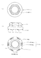
かかる従来のナットの一例を図5および図6を参照して説明する。図5は、従来のナットの一例の外観図であり、(a)は正面図、(b)は底面図である。図6は、爪が取付部材の表面に食い込む状況を説明する図である。
【0005】
図5に示すごとく、従来のナット10の車両のシャーシなどの取付部材30に当接する一側面10aに、周方向に突条の爪12,12…が複数(図5にあっては3つ)突設される。この爪12は、断面が三角状または半円弧状であり、しかも周方向にその突設高さhはほぼ一定である。
【0006】
ナット10の締め付けにより、図6のごとく、取付部材30の表面に爪12,12…が当接すると、表面の絶縁層として作用する塗装膜30aを爪12,12…がすじ状に取り除き、さらには取付部材30の表面に食い込む。もって、ナット10が取付部材30に電気的接続される。
【0007】
【発明が解決しようとする課題】
ところで、ナット10は安価に大量生産されることが望ましい。そこで、一般的には圧造による型打ちで外形を成形し、最終工程で雌ネジ14が刻設される。この外形を成型する一工程において、爪12,12…も成形されており、爪12の周方向の両端面はダレが生じて角が丸くなってしまう。そこで、図6に示すごとく、ナット10が締め付けられて爪12が取付部材30の表面に当接した際に、塗装膜30aを確実に取り除くことが困難であり、また取付部材30の表面に食い込みにくいものであった。さらに、爪12は周方向に突設高さhがほぼ一定であることで、取付部材30の表面への食い込みが悪い要因ともなっている。この結果、取付部材30とナット10との電気的接続が確実になされない、という不具合があった。また、確実な電気的接続を得るためには、大きな締め付けトルクでナット10を締め付けなければならない。
【0008】
本発明は、上述のごとき従来技術の不具合を改善すべくなされたもので、塗装膜を確実に取り除くことができるとともに取付部材の表面に食い込み易く、確実に電気的接続が得られる電気的接続用爪付きナットおよびその製造方法を提供することを目的とする。
【0009】
【課題を解決するための手段】
かかる目的を達成するために本発明の電気的接続用爪付きナットは、雄ネジに螺合して取付部材に一側面を当接させて前記取付部材に電気的接続するナットであって、前記ナットの前記一側面に、周方向の突条で爪を複数突設し、前記爪を前記ナットの締め付け回転方向で前半部分の突設高さを低くし段差を設けて後半部分の突設高さを高くし、前記段差による前記後半部分の前端面と前記後半部分のなす角を鋭角にするとともに、前記後半部分の突設高さが前記前端面で最も高く後側ほど低くなるようにし、締め付け固定に伴い前記爪の前記後半部分の前記前端面が前記取付部材の表面を切削もしくは食い込むように構成されている。
【0010】
また、本発明の電気的接続用爪付きナットの製造方法は、雄ネジに螺合して取付部材に一側面を当接させるナットの素材の前記一側面に、圧造による型打ちで周方向に突条を複数突設し、次の型打ちにより、前記ナットの締め付け回転方向で前記突条の前半部分をネジ軸方向に押し潰して段差を設けて後半部分より突設高さを低くして、前記段差による前記後半部分の前端面と前記後半部分のなす角を鋭角として爪を形成し、さらに別の工程で前記素材に雌ネジを刻設するものである。
【0011】
そして、圧造による型打ちで、前記突条の突設高さが中央で最も高い円弧状とし、次の型打ちにより、突設高さが最も高い中央より前半部分を押し潰して突設高さを低くして前記爪を形成することもできる。
【0012】
【発明の実施の形態】
以下、本発明の一実施例を図1ないし図4を参照して説明する。図1は、本発明の電気的接続用爪付きナットの一実施例の外観図であり、(a)は平面図、(b)は正面図、(c)は底面図である。図2は、爪の成形を示す図であり、(a)は前半部分が押し潰される工程前の突条の図、(b)は前半部分が押し潰されて爪の最終形状に成型された図である。図3は、本発明の電気的接続用爪付きナットの爪が塗装膜を取り除きさらに取付部材の表面に食い込むのを説明する図である。図4は、本発明の電気的接続用爪付きナットを圧造による複数の工程よりその外形を成形し、最終工程で雌ネジを刻設する製造方法を示す図である。
【0013】
まず、本発明の電気的接続用爪付きナットの形状を図1および図2を参照して説明する。本発明のナット20は、図5および図6に示すナット10とは、一側面20aに突設される爪22,22…の形状が異なるだけであり、爪22,22…が突設される個数の相違は問題とならない。
【0014】
本発明にあっては、まず図2(a)に示すごとく、ナット20の取付部材30に当接する一側面20aに周方向に6ヶの突条28,28…が突設される。突条28,28…の断面は、従来例の爪12,12…と同様に三角状または半円弧状である。しかも、突条28,28…の突設高さは、周方向の中央が最も高い円弧状である。なお、突条28,28…の突設高さを周方向の中央で最も高い円弧状とするには、圧造の型を突条28,28…の高さが円弧状となるようにしても良いことは勿論であるが、突条28,28…の周方向の両端側が中央より金属の流動性が悪いことを用いて結果として中央が高くなるようにしても良い。そして次に、ナット20の締め付け回転方向で、突条28,28…の中央より前半部分22a,22a…ががネジ軸方向に型26で押し潰されて、図2(b)のごとく、突設高さが低くされ、押し潰されてない後半部分22b,22b…との間に段差が設けられる。この押し潰しにより、突条28,28…の幅はさほど広くなく金属素材の流れが良くまた剪断作用によって、段差による後半部分22b,22b…の前端面と後半部分22b,22b…のなす角は、略90度の鋭角に形成される。もって、爪22,22…が形成される。
【0015】
かかる形状の本発明の電気的接続用爪付きナットにあっては、図3に示すごとく、取付部材30の表面に爪22,22…が当接すると、後半部分22b,22b…とその前端面の角が鋭角であるので、塗装膜30aを確実に取り除き、しかも金属切削加工用のバイトと同様に、後半部分22b,22b…の突設高さが前端面で最も高く後側ほど低くなるようにして、逃げ角θを設けているために、従来のナット10の爪12のごとく食い込みが妨げられるようなことがなく、取付部材30の表面に確実な食い込みが得られる。そこで、本発明のナット20は取付部材30に確実に電気的接続がなされる。実験によれば、取付部材30に爪22,22…が食い込んで確実に電気的接続させるには、ナット20を約0.5〜1.5N.mの締め付けトルクで締め付ければ充分であった。これに対して、図5および図6にし示す従来例にあっては、確実な電気的接続を得るためには、約2.5〜4.0N.mの締め付けトルクが必要であった。かかる点からも、本発明では、より低い締め付けトルクで安定した電気的接続が得られる。
【0016】
次に上述のごとき構造の本発明の電気的接続用爪付きナットの製造方法の一例を図4を参照して説明する。図4で説明する製造方法は、圧造によりまず外形を成形し、最終工程で雌ネジを刻設するものである。第1工程として、図4(a)のごとき、所定の容積の円柱状で導電性の金属素材としての鋼材を準備し、これを第2工程で、図4(b)のごとく、次の型打ちにより上下から押し潰して偏平にするとともに上下面に浅い孔を設ける。さらに、第3工程で、図4(c)のごとく、さらなる型打ちによりさらに偏平に押し潰すとともに上下の面の孔を大きくしかも深くするとともに、一側面20aに周状の突条28,28…を形成する。そしてさらに、第4工程で、図4(d)のごとく、上下の面の孔を貫通させるとともに、突条28,28…の前半部分22a,22a…を押し潰して爪22,22…を完成させる。そしてまた、最終工程の第5工程にて、貫通させた孔に雌ネジ24を刻設して本発明の電気接続用爪付きナットが完成される。
【0017】
この圧造による製造方法は、外形および爪を切削加工などで製造する方法に比較して、量産に好都合で安価に製造し得ることは勿論である。
【0018】
なお、上記実施例においては、周方向に突設された突条28,28…の前半部分22a,22a…を圧造により押し潰して爪22,22…形成したが、これに限られず、ネジ軸方向にプレス成形により前半部分22a,22a…を押し潰しても良く、さらに前半部分22a,22a…を切削加工して突設高さを低くし、もって後半部分22b,22b…と段差によるその前端面の角を鋭角としても良い。また、爪22,22…の突設高さは、後半部分22b,22b…の前端面が最も高く後側が低ければ良く、円弧状に限られず、直線状に突設高さが低く変化されても良い。さらに、上記実施例では圧造により外形を成形して最終工程で雌ネジ24を刻設するように説明したが、後半部分22b,22b…とその前端面のなす角が鋭角に形成されるならば、いかなる順序の工程によって本発明の電気的接続用爪付きナットが形成されても良い。そしてまた、上記実施例では、突条28,28…の中央で前半部分22a,22a…と後半部分22b,22b…としているが、中央の位置に限られず、前側などの一方に偏った位置で前半部分22a,22a…と後半部分22b,22b…としても良く、後半部分22b,22b…の前端面が最も突設高さが高くなるように構成すれば良い。
【0019】
【発明の効果】
以上説明したように本発明の電気的接続用爪付きナットは構成されているので、以下のごとき格別な効果を奏する。
【0020】
請求項1記載の電気的接続用爪付きナットにあっては、爪の後半部分と段差による後半部分の前端面のなす角が鋭角であるので、取付部材の表面の塗装膜を容易に取り除くとともに取付部材の表面に食い込み易く、しかも爪の後半部分の突設高さがその前端面で最も高く後側ほど低くしたので、爪が取付部材に食い込んでも、切削加工用のバイトと同様に逃げ角があり、食い込みが妨げられない。もって、食い込みが容易であり、確実な電気的接続が得られる。そして、この食い込みの良さにより、従来技術よりも低い締め付けトルクで充分な電気的接続が得られる。
【0021】
また、本発明の電気的接続用爪付きナットの製造方法にあっては、以下のごとき格別な効果を奏する。
【0022】
請求項2記載の電気的接続用爪付きナットの製造方法にあっては、圧造により外形を成形し、しかも型打ちにより突条の前半部分を押し潰して後半部分と段差によるその前端面のなす角を鋭角として爪を形成し、その後の工程で雌ネジを刻設するので、量産に好適であって、安価に製造できる。
【0023】
請求項3記載の電気的接続用爪付きナットの製造方法にあっては、爪の後半部分に逃げ角を備える工程をも圧造により行っており、外形の成形工程の一部として同時に行うことができ、特別に工程が増加するものでなく、安価に製造することができる。
【図面の簡単な説明】
【図1】 本発明の電気的接続用爪付きナットの一実施例の外観図であり、(a)は平面図、(b)は正面図、(c)は底面図である。
【図2】 爪の成形を示す図であり、(a)は前半部分が押し潰される工程前の突条の図、(b)は前半部分が押し潰されて爪の最終形状に成型された図である。
【図3】 本発明の電気的接続用爪付きナットの爪が塗装膜を取り除きさらに取付部材の表面に食い込むのを説明する図である。
【図4】 本発明の電気的接続用爪付きナットを圧造による複数の工程よりその外形を成形し、最終工程で雌ネジを刻設する製造方法を示す図である。
【図5】 従来のナットの一例の外観図であり、(a)は正面図、(b)は底面図である。
【図6】 爪が取付部材の表面に食い込む状況を説明する図である。
【符号の説明】
10,20 ナット
10a,20a 一側面
12,22 爪
14,24 雌ネジ
22a 前半部分
22b 後半部分
28 突条
30 取付部材
30a 塗装膜[0001]
BACKGROUND OF THE INVENTION
According to the present invention, an antenna or the like having a male screw on a fixing member is fastened and fixed to a mounting member such as a vehicle with a nut, and a claw of the nut bites into the mounting member to ensure electrical connection. The present invention relates to a nut with a connection claw and a method for manufacturing the same.
[0002]
[Prior art]
In an in-vehicle antenna, a fixing member engraved with a male screw is inserted into a hole formed in a mounting member such as a vehicle chassis, and a nut is screwed into the male screw from the inside. Fastened and fixed to the mounting member. Here, one end of the cable core wire is electrically connected to the antenna element of the vehicle-mounted antenna and is appropriately introduced into the vehicle, and the outer conductor of the antenna is appropriately electrically connected to the chassis or the like to be grounded.
[0003]
Therefore, conventionally, a claw is provided on the nut for fastening and fixing the antenna to the mounting member, and the fastening member is tightened and fixed so that the claw bites into the surface of the mounting member and makes an electrical connection. It is configured to be electrically connected to a mounting member such as a chassis through a male screw and a conductive nut sequentially.
[0004]
An example of such a conventional nut will be described with reference to FIGS. FIG. 5 is an external view of an example of a conventional nut, where (a) is a front view and (b) is a bottom view. FIG. 6 is a diagram illustrating a situation where the claw bites into the surface of the mounting member.
[0005]
As shown in FIG. 5, a plurality of protrusion claws 12, 12... Are provided in the circumferential direction on one side surface 10 a that contacts a mounting member 30 such as a vehicle chassis of a conventional nut 10 (three in FIG. 5). Projected. The claw 12 has a triangular or semicircular cross section, and its protruding height h is substantially constant in the circumferential direction.
[0006]
When the claws 12, 12... Come into contact with the surface of the mounting member 30 by tightening the
[0007]
[Problems to be solved by the invention]
By the way, it is desirable that the
[0008]
The present invention has been made to improve the problems of the prior art as described above, and can be used for electrical connection that can reliably remove the coating film and can easily bite into the surface of the mounting member. An object of the present invention is to provide a nut with a claw and a method for manufacturing the same.
[0009]
[Means for Solving the Problems]
In order to achieve this object, the nut with an electrical connection claw of the present invention is a nut that is screwed into a male screw and brought into contact with one side of the mounting member and electrically connected to the mounting member, On the one side of the nut, a plurality of claws are provided with a circumferential protrusion, and the protrusion height of the rear half is provided by lowering the protrusion height of the first half in the tightening rotation direction of the nut. Increasing the height, making the angle formed by the front end surface of the latter half part and the latter half part due to the step difference, and the projecting height of the latter part highest on the front end face and lower on the rear side, The front end surface of the second half portion of the claw is configured to cut or bite the surface of the mounting member along with tightening and fixing.
[0010]
In addition, the manufacturing method of the nut with an electrical connection claw of the present invention is the circumferential direction by stamping by stamping on the one side of the nut material that is screwed into the male screw and abuts one side of the mounting member. Protruding multiple ridges, and by the next stamping, the first half of the ridge is crushed in the screw shaft direction in the direction of tightening rotation of the nut to provide a step, and the protruding height is made lower than the latter half The nail is formed with an acute angle formed by the front end surface of the latter half portion and the latter half portion due to the step, and a female screw is engraved in the material in a further step.
[0011]
Then, by stamping by forging, the projecting height of the protrusion is the highest in the center, and by the next stamping, the first half part is crushed from the center where the projecting height is the highest, and the projecting height The nail can be formed by lowering the height.
[0012]
DETAILED DESCRIPTION OF THE INVENTION
An embodiment of the present invention will be described below with reference to FIGS. FIG. 1 is an external view of an embodiment of a nut with an electrical connection claw of the present invention, (a) is a plan view, (b) is a front view, and (c) is a bottom view. 2A and 2B are diagrams showing nail molding, where FIG. 2A is a view of a ridge before the first half portion is crushed, and FIG. 2B is a final shape of the nail after the first half portion is crushed. FIG. FIG. 3 is a view for explaining that the claw of the nut with an electrical connection claw of the present invention removes the coating film and further bites into the surface of the mounting member. FIG. 4 is a view showing a manufacturing method in which the outer shape of the nut with an electrical connection claw of the present invention is formed by a plurality of steps by forging and an internal thread is engraved in the final step.
[0013]
First, the shape of the nut with an electrical connection claw of the present invention will be described with reference to FIGS. The
[0014]
In the present invention, as shown in FIG. 2 (a), six
[0015]
In the nut with an electrical connection claw of the present invention having such a shape, as shown in FIG. 3, when the
[0016]
Next, an example of a method for manufacturing the nut with a claw for electrical connection of the present invention having the above-described structure will be described with reference to FIG. The manufacturing method illustrated in FIG. 4 is a method in which an outer shape is first formed by forging and a female screw is engraved in the final process. As a first step, as shown in FIG. 4 (a), a steel material as a cylindrical and conductive metal material having a predetermined volume is prepared, and in the second step, as shown in FIG. It is flattened by crushing from above and below by striking and shallow holes are provided on the top and bottom surfaces. Further, in the third step, as shown in FIG. 4 (c), further flattening is performed by further stamping, the holes on the upper and lower surfaces are enlarged and deepened, and the
[0017]
Of course, this manufacturing method by forging is convenient for mass production and can be manufactured at a lower cost than the method of manufacturing the outer shape and the nail by cutting or the like.
[0018]
In the above-described embodiment, the
[0019]
【The invention's effect】
As described above, since the nut with the pawl for electrical connection according to the present invention is configured, the following special effects can be obtained.
[0020]
In the nut with an electrical connection nail according to
[0021]
Moreover, in the manufacturing method of the nail | claw with an nail | claw for electrical connection of this invention, there exist the following special effects.
[0022]
In the manufacturing method of the nut with an electrical connection claw according to
[0023]
In the method of manufacturing a nut with an electrical connection claw according to claim 3, the step of providing a clearance angle in the second half of the claw is also performed by forging, and can be simultaneously performed as part of the outer shape forming step. In addition, the number of processes is not increased, and it can be manufactured at low cost.
[Brief description of the drawings]
FIG. 1 is an external view of an embodiment of a nut with an electrical connection claw of the present invention, (a) is a plan view, (b) is a front view, and (c) is a bottom view.
FIGS. 2A and 2B are diagrams showing the formation of a nail, FIG. 2A is a view of a ridge before the first half portion is crushed, and FIG. 2B is a final shape of the nail after the first half portion is crushed. FIG.
FIG. 3 is a view for explaining that a claw of a nut with an electrical connection claw of the present invention removes a coating film and further bites into a surface of an attachment member.
FIG. 4 is a view showing a manufacturing method in which an external shape of a nut with a claw for electrical connection according to the present invention is formed by a plurality of steps by forging and a female screw is engraved in the final step.
FIG. 5 is an external view of an example of a conventional nut, (a) is a front view, and (b) is a bottom view.
FIG. 6 is a diagram for explaining a situation where the claw bites into the surface of the mounting member.
[Explanation of symbols]
10, 20 Nut 10a, 20a One
Claims (3)
Priority Applications (1)
| Application Number | Priority Date | Filing Date | Title |
|---|---|---|---|
| JP2001322740A JP4169960B2 (en) | 2001-10-19 | 2001-10-19 | Nut with claw for electrical connection and manufacturing method thereof |
Applications Claiming Priority (1)
| Application Number | Priority Date | Filing Date | Title |
|---|---|---|---|
| JP2001322740A JP4169960B2 (en) | 2001-10-19 | 2001-10-19 | Nut with claw for electrical connection and manufacturing method thereof |
Publications (2)
| Publication Number | Publication Date |
|---|---|
| JP2003130027A JP2003130027A (en) | 2003-05-08 |
| JP4169960B2 true JP4169960B2 (en) | 2008-10-22 |
Family
ID=19139739
Family Applications (1)
| Application Number | Title | Priority Date | Filing Date |
|---|---|---|---|
| JP2001322740A Expired - Fee Related JP4169960B2 (en) | 2001-10-19 | 2001-10-19 | Nut with claw for electrical connection and manufacturing method thereof |
Country Status (1)
| Country | Link |
|---|---|
| JP (1) | JP4169960B2 (en) |
Families Citing this family (2)
| Publication number | Priority date | Publication date | Assignee | Title |
|---|---|---|---|---|
| JP4641244B2 (en) * | 2005-10-18 | 2011-03-02 | カルソニックカンセイ株式会社 | Nail fixing structure for decorative member |
| JP5670662B2 (en) * | 2010-07-06 | 2015-02-18 | エヌアイシ・オートテック株式会社 | Connecting nut for fixing frame material |
-
2001
- 2001-10-19 JP JP2001322740A patent/JP4169960B2/en not_active Expired - Fee Related
Also Published As
| Publication number | Publication date |
|---|---|
| JP2003130027A (en) | 2003-05-08 |
Similar Documents
| Publication | Publication Date | Title |
|---|---|---|
| JP2592690Y2 (en) | Terminal fitting | |
| US9647352B2 (en) | Electric wire with terminal | |
| US9954308B2 (en) | Terminal-attached electric wire | |
| US5941738A (en) | Battery terminal | |
| WO2015079988A1 (en) | Grounding terminal | |
| JPH09289054A (en) | Assembled structure of terminal metal fitting | |
| JP4169960B2 (en) | Nut with claw for electrical connection and manufacturing method thereof | |
| JPH0127721B2 (en) | ||
| US4797111A (en) | Terminal for side-mount battery | |
| JP2004146126A (en) | Plug cap and manufacturing method of the same | |
| JP3429357B2 (en) | Crimped wire terminals with mechanical locking | |
| JP3526214B2 (en) | Connection terminal nut locking structure | |
| JP2608084B2 (en) | Tapping screw for removing paint and method of manufacturing the same | |
| US5429512A (en) | Terminal arrangement | |
| JP3560193B2 (en) | Connection terminals for high-voltage wires | |
| JP2982654B2 (en) | Battery terminal | |
| JP3060360B2 (en) | Connection terminal for battery electrode | |
| JPH0119822Y2 (en) | ||
| JP2002124246A (en) | Connection terminal for battery and its manufacturing method | |
| JP2715360B2 (en) | Terminal | |
| JP4297342B2 (en) | Earth terminal | |
| JPH084690Y2 (en) | Pressure contact terminal | |
| JP3185138B2 (en) | Manufacturing method of terminal screw with guide leg | |
| JP2015088411A (en) | Ground terminal | |
| JPH0524134Y2 (en) |
Legal Events
| Date | Code | Title | Description |
|---|---|---|---|
| A621 | Written request for application examination |
Free format text: JAPANESE INTERMEDIATE CODE: A621 Effective date: 20040924 |
|
| A977 | Report on retrieval |
Free format text: JAPANESE INTERMEDIATE CODE: A971007 Effective date: 20070427 |
|
| A131 | Notification of reasons for refusal |
Free format text: JAPANESE INTERMEDIATE CODE: A131 Effective date: 20080205 |
|
| A521 | Written amendment |
Free format text: JAPANESE INTERMEDIATE CODE: A523 Effective date: 20080326 |
|
| TRDD | Decision of grant or rejection written | ||
| A01 | Written decision to grant a patent or to grant a registration (utility model) |
Free format text: JAPANESE INTERMEDIATE CODE: A01 Effective date: 20080805 |
|
| A01 | Written decision to grant a patent or to grant a registration (utility model) |
Free format text: JAPANESE INTERMEDIATE CODE: A01 |
|
| A61 | First payment of annual fees (during grant procedure) |
Free format text: JAPANESE INTERMEDIATE CODE: A61 Effective date: 20080806 |
|
| FPAY | Renewal fee payment (event date is renewal date of database) |
Free format text: PAYMENT UNTIL: 20110815 Year of fee payment: 3 |
|
| R150 | Certificate of patent or registration of utility model |
Free format text: JAPANESE INTERMEDIATE CODE: R150 |
|
| FPAY | Renewal fee payment (event date is renewal date of database) |
Free format text: PAYMENT UNTIL: 20110815 Year of fee payment: 3 |
|
| FPAY | Renewal fee payment (event date is renewal date of database) |
Free format text: PAYMENT UNTIL: 20120815 Year of fee payment: 4 |
|
| FPAY | Renewal fee payment (event date is renewal date of database) |
Free format text: PAYMENT UNTIL: 20120815 Year of fee payment: 4 |
|
| FPAY | Renewal fee payment (event date is renewal date of database) |
Free format text: PAYMENT UNTIL: 20130815 Year of fee payment: 5 |
|
| LAPS | Cancellation because of no payment of annual fees |