JP4169552B2 - Transporter - Google Patents
Transporter Download PDFInfo
- Publication number
- JP4169552B2 JP4169552B2 JP2002264481A JP2002264481A JP4169552B2 JP 4169552 B2 JP4169552 B2 JP 4169552B2 JP 2002264481 A JP2002264481 A JP 2002264481A JP 2002264481 A JP2002264481 A JP 2002264481A JP 4169552 B2 JP4169552 B2 JP 4169552B2
- Authority
- JP
- Japan
- Prior art keywords
- priority
- motor
- switch
- main
- sub
- Prior art date
- Legal status (The legal status is an assumption and is not a legal conclusion. Google has not performed a legal analysis and makes no representation as to the accuracy of the status listed.)
- Expired - Fee Related
Links
- 238000003825 pressing Methods 0.000 description 9
- 230000007935 neutral effect Effects 0.000 description 8
- 238000000034 method Methods 0.000 description 4
- 230000002441 reversible effect Effects 0.000 description 4
- 238000001514 detection method Methods 0.000 description 3
- 238000010586 diagram Methods 0.000 description 3
- 235000021270 cold food Nutrition 0.000 description 2
- 230000000694 effects Effects 0.000 description 2
- 238000010438 heat treatment Methods 0.000 description 2
- 235000021268 hot food Nutrition 0.000 description 2
- 238000005192 partition Methods 0.000 description 2
- 238000010792 warming Methods 0.000 description 2
- 230000001276 controlling effect Effects 0.000 description 1
- 238000001816 cooling Methods 0.000 description 1
- 238000005516 engineering process Methods 0.000 description 1
- 238000012986 modification Methods 0.000 description 1
- 230000004048 modification Effects 0.000 description 1
- 230000000149 penetrating effect Effects 0.000 description 1
- 238000005057 refrigeration Methods 0.000 description 1
- 230000001105 regulatory effect Effects 0.000 description 1
Images


Landscapes
- Handcart (AREA)
Description
【0001】
【発明の属する技術分野】
本発明は、パワーアシスト機能を備えた運搬車に関する。
【0002】
【従来の技術】
病院等で使用される配膳車において、特に大型で重量も大きいものについては、いわゆるパワーアシスト機能を備えたものが知られている。このパワーアシスト機能は、モータを搭載して車輪と連結し、ハンドルを持って人手により配膳車を引きまたは押し操作する際に、このハンドルの操作に伴って駆動輪をモータで駆動して自走させることにより、走行操作を助勢するものである(例えば、特許文献1参照)。
一方、この種のパワーアシスト機能を備えた配膳車の一部には、上記したハンドルと、モータの駆動を制御する操作部との組を、配膳車の前後両側にそれぞれ設けたものがある。この場合、両操作部はいずれか一方のみが選択的に作動可能状態とされる必要があり、従来は、例えば電源の入り切りを行う電源スイッチの装備された主操作側に、どちらの操作部を優先的に作動可能状態とするかを切り替える切替スイッチを設けるようにしていた。
【0003】
【特許文献1】
特開平9−294638号公報
【0004】
【発明が解決しようとする課題】
そのため、例えば切替スイッチの設けられていない副操作側から運転しようとした場合であって、主操作側の操作部に優先権が設定されていたときは、一旦主操作側に回って切替スイッチの操作をしなければならず、面倒であった。
また別の方法として、主操作側、副操作側に拘わらず、先にハンドル操作をした方に操作部の優先権を与えるものも知られている。
しかしながらこの方法は、主副いずれか一方のみから運転する場合には便利であるが、作業者二人が主副両側に分かれて運転する場合は、いずれに優先権が設定されたか曖昧となり、主副一方で配膳車を停止させるべくハンドルを放した場合でも、他方に優先権が設定されていると、それが利いて配膳車が止まらないという事態が起き、却って運転がし難い場合もあった。
本発明は上記のような事情に基づいて完成されたものである。
【0005】
【課題を解決するための手段】
請求項1の発明は、手動による走行操作を助勢するために車輪がモータにより駆動可能とされ、かつこのモータの駆動を制御する操作部が車両本体の前後両側に設けられた運搬車において、前記両操作部はいずれか一方のみが選択的に作動可能状態とされるとともに、前記車両本体の前後両側にはそれぞれ優先スイッチが設けられ、いずれかの優先スイッチが操作された場合にこの優先スイッチが設けられた側の操作部を優先的に作動可能状態に設定し得る手段が設けられ、かつ、前記車両本体の前後両側には障害物を検知するセンサが設けられて、前記優先スイッチが操作された側とは反対側のセンサが作動状態とされるようになっているとともに、前記センサにより障害物が検知された場合に前記モータへの通電を遮断しかつ前記モータに電磁ブレーキを作動させる制御手段と、前記電磁ブレーキの作動状態を検知する手段とが設けられており、前記電磁ブレーキが解除されているときには前記優先スイッチの操作が無効とされる操作無効手段が設けられている構成としたところに特徴を有する。
【0006】
請求項2の発明は、請求項1に記載のものにおいて、前記車両本体の前後いずれか一方の側には、対応するセンサを非作動状態に保持し得る切替スイッチが設けられているところに特徴を有する。
請求項3の発明は、請求項1または請求項2に記載のものにおいて、前記車両本体の前後いずれか一方の側には、電源の入り切りを操作する電源スイッチが設けられ、電源が入った場合には、この電源スイッチが設けられた側の前記操作部が作動可能状態とされるようになっているところに特徴を有する。
【0007】
【発明の作用及び効果】
<請求項1の発明>
作業者が運搬車の前後いずれかに回り、回った側で優先スイッチを操作すれば、この操作をした側の操作部が優先的に作動可能状態とされる。したがって引き続いて、モータ駆動による助勢力を受けつつ運搬車の走行操作を行うことができる。作業者が運転すべく回った側で、同側の操作部の優先権が得られるから、直ちに運転ができて便利であり、また操作部が利いていることを自覚しつつ運転できるから、正確かつ円滑な運転を期することができる。
運搬車が走行中には、いずれの側の優先スイッチを操作したとしても、操作自体が無効とされ、操作部の優先権が不用意に切り替わってしまうこと等が防止される。
【0008】
<請求項2の発明>
センサが障害物を検知すると、モータへの通電が遮断されるとともに電磁ブレーキが作動して運搬車が急停止されるが、そののち運搬車の体勢を直すべく動かす場合は、切替スイッチが設けられた側において優先スイッチを操作するとともに、切替スイッチにより対応するセンサを非作動状態に保持すると、モータへの通電が可能でかつ電磁ブレーキも解除されるから、引き続いて操作部を作動することで、運搬車を容易に動かすことができる。
<請求項3の発明>
運転を開始するに当たって電源スイッチで電源を入れると、同電源スイッチを設けた側の操作部が作動可能状態とされる。電源を入れる操作をした側から運転する場合には、優先スイッチを操作しないでも同側の操作部が優先的に作動可能状態とされるから、操作が簡便化されて使い勝手に優れたものとなる。
【0009】
【発明の実施の形態】
以下、本発明を温冷配膳車に適用した一実施形態を図1ないし図5に基づいて説明する。
温冷配膳車は、図1に示すように、表裏両面の開口された矩形状の断熱箱体からなる配膳車本体10を備えている。なお以下では、図1の左側を前方として説明する。本体10内は、図示しない断熱壁により前後方向に3つの部屋に仕切られ、さらに各部屋が断熱性の仕切壁により前後2つに仕切られて、合計6室が形成されており、前方から順次に、冷蔵室12A、2つの温蔵室11A,11B、2つの冷蔵室12B,12C及び温蔵室11Cとされている。これらは隣り合う温蔵室11と冷蔵室12とが対をなし、それぞれに観音開き式の扉13が装備されている。
【0010】
本体10の上面には機械室14が設けられ、温蔵室11を加熱する加熱装置や冷蔵室12を冷却する冷凍ユニットが装備されている。
対をなす温蔵室11と冷蔵室12には、図示はしないが複数段にわたって棚が形成されており、温食と冷食とを区分けして載置したトレイが仕切壁を貫通しつつ棚に載せられることにより、一つのトレイに載せられた温食が温蔵室11に、冷食が冷蔵室12にそれぞれ収容されて、温蔵または冷蔵されるようになっている。
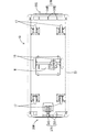
本体10の底面には、図2にも示すように、前後方向の中央部に左右一対の駆動輪16が装備されているとともに、前後両端部に左右一対ずつの自在輪17が装備されている。駆動輪16の近傍には、この駆動輪16を正逆両方向に駆動可能な可逆モータM(図5参照)が装備されている。
【0011】
温冷配膳車を走行操作する場合、本体10の前面側(図1の左側)に主操作側20Mが、後面側に副操作側20Sがそれぞれ設定されている。
主操作側20Mでは、本体10の前面に主制御ボックス21Mが設けられ、この主制御ボックス21Mには、図3にも示すように、主ハンドル22Mが軸23を中心として回動可能に支持されており、ばね25の弾力等を受けて、常には上方に直立した中立姿勢を取るように付勢されている。
作業者が主操作側20Mに回った場合は、主ハンドル22Mを前方(図1の矢線A方向)に回動して引くことにより配膳車が前進され、後方(同図の矢線B方向)に回動して押すことにより後退される。この主ハンドル22Mの回動に伴い主操作側可変抵抗31M(図5)からの出力が変化して、主ハンドル22Mの前傾と後傾とが検知され、主ハンドル22Mが前傾したときには、モータMに対して正方向に通電されて前進用に正転駆動され、一方、後傾したときには、モータMに対して逆方向に通電されて後退用に逆転駆動される。また、主ハンドル22Mの回動量に応じて上記の主操作側可変抵抗31Mの出力が変化することにより、モータMの出力が大小制御されるようになっている。
【0012】
一方、副操作側20Sでは、本体10の後面に副制御ボックス21Sが設けられて副ハンドル22Sが回動可能に軸支されているが、その構造並びに基本的な機能については、主操作側20Mと同様である。
簡単に繰り返すと、副ハンドル22Sは常には上方に直立した中立姿勢を取り、副操作側20Sでは、副ハンドル22Sを後方(図1の矢線C方向)に回動して引くことにより配膳車が後退され、前方(図1の矢線D方向)に回動して押すことにより前進される。副ハンドル22Sの前傾と後傾とは副操作側可変抵抗31S(図5)で検知され、前傾したときにはモータMが前進用に正転駆動され、後傾したときには後退用に逆転駆動され、また回動量に応じてモータMの出力が大小制御される。
【0013】
なお、上記した両ハンドル22M,22Sの前傾と後傾との回動量を規制する手段としては、主ハンドル22Mを例に取ると、図3,4に示すように、ハンドル軸23の両端にストッパ板27が設けられている。ストッパ板27は略扇形をなし、弧状部分の上下両側に直線部28U,28Dが形成されており、弧状部分を本体10の前壁10Aに向けた姿勢で取り付けられている。
そして、主ハンドル22Mが図4(A)の鎖線に示す中立位置から前方に回動され、約30度回動されると、同図の実線に示すように、ストッパ板27の下側の直線部28Dが本体10の前壁10Aに当たることでそれ以上の回動が規制される。一方、中立位置から後方に回動され、約10度回動されると、図4(B)に示すように、上側の直線部28Uが前壁10Aに当たって回動が規制されるようになっている。
従来では、主ハンドル22Mの後傾(図4(B)参照)については、主ハンドル22Mを前壁10A等に設けたクッション材に当てることで回動規制していたところを、前傾、後傾とも回動規制をストッパ板27で賄うようにしたから、部品点数や組付工数の削減が図られる。
なお、副ハンドル22S側も同様である。
【0014】
また、本実施形態の配膳車には、特に押し操作している場合に障害物が視認し難いことに鑑み、その検知用のセンサが設けられている。
図1及び図2に示すように、本体10の下端部の回りには、衝撃吸収用のバンパ33が装着され、このバンパ33のうちの後面(図1,2の右側)には、接触型センサである第1ベルトスイッチ34Mが装着されているとともに、その下面側には、L型ブラケット36を介して非接触型センサである図示5個の第1近接センサ35Mが装着されている。この第1ベルトスイッチ34Mと第1近接センサ35Mとの組が、主操作側センサ37Mとなる。
一方、バンパ33の前面には、接触型センサである第2ベルトスイッチ34Sが装着されているとともに、その下面側に、L型ブラケット36により非接触型センサである図示5個の第2近接センサ35Sが装着されており、この第2ベルトスイッチ34Sと第2近接センサ35Sとの組が、副操作側センサ37Sとなる。
【0015】
上記の主操作側センサ37Mと副操作側センサ37Sとは、図5に示すモータMの駆動制御回路に組み込まれている。ベルトスイッチ34M,34Sが作動状態にあるときには、壁等の障害物に接触した場合に検知信号を出力し、制御手段30がこの検知信号を受けると、モータMへの通電を遮断するとともに電磁ブレーキMBを作用させるようになっている。
一方、近接センサ35M,35Sは例えば光電式であって、投光部からの投光を障害物で反射させ、その反射光を受光部で受けた場合の反射角度が所定角度以内となると、検知信号を出力するようになっており、制御手段30がこの検知信号を受けると、モータMへの通電を遮断するようになっている。
【0016】
なお、上記したベルトスイッチ34M,34Sと近接センサ35M,35Sの作動状態と非作動状態とを切り替えるべく切替スイッチ41が備えられており、図3に示すように、上記した主制御ボックス21Mの操作パネル40上に、電源スイッチ42、充電残量のメータ43等とともに設置されている。
切替スイッチ41は例えばロータリ型であって、位置I〜IIIに切り替え可能であり、詳しい説明は省略するが、位置Iでは、各センサの組37Mまたは37Sにおいて、ベルトスイッチ34M,34Sと、近接センサ35M,35Sの両方が作動状態とされ、位置IIでは、ベルトスイッチ34M,34Sは作動状態とされるものの、近接センサ35M,35Sは非作動状態とされ、また位置III では、ベルトスイッチ34M,34Sと近接センサ35M,35Sの両方が非作動状態とされる。
例えば通常走行時には位置Iに、狭い通路を走行する場合には位置IIに、また、配膳車が障害物に当たってその体勢を直す緊急時には位置III にそれぞれ切り替えられる。なお切替スイッチ41は、位置Iと位置IIでは機械的に保持可能となっているのに対して、緊急用の位置III については、人手により押さえていて初めて同位置に保持でき、保持力を除去すると位置Iに自動的に復帰するモーメンタリ構造となっている。
【0017】
さて、この実施形態では、モータMの駆動制御等を、主操作側20Mと副操作側20Sとのいずれで優先的に行うかを設定する手段が備えられている。そのため、主制御ボックス21Mと副制御ボックス21Sには、それぞれ優先スイッチ46M,46Sが装備され、図5のモータMの駆動制御回路に優先権切替部45として組み込まれている。主操作側優先スイッチ46Mは、図3に示されている。
主操作側優先スイッチ46Mは、常閉のモーメンタリ型であって、押圧操作により開放し、手を放すと閉鎖状態に戻るようになっている。一方の副操作側優先スイッチ46Sは、常開のモーメンタリ型であって、押圧操作により閉鎖し、手を放すと開放状態に戻るようになっている。
【0018】
続いて、本実施形態の作用を説明する。
配膳車を移動する場合は、ハンドル22に手を添えて引きまたは押すことで行われるが、この操作を行うべく主操作側20Mまたは副操作側20Sに回ったら、回った側にある優先スイッチ46Mまたは46Sを押圧操作する。
図5の状態から、例えば副操作側20Sで優先スイッチ46Sを押圧してこれを閉じると、優先権切替部45においてリレーX2がオンして自己保持され、これにより制御手段30では副操作側20Sに優先権があると定義される。一方、この状態から、主操作側20Mで優先スイッチ46Mを押圧してこれを開くと、リレーX2の自己保持が解除されてオフとなり、これにより主操作側20Mに優先権があると定義される。この優先権が設定された操作側20Mまたは20Sでのみ、モータMの駆動制御等を行うことができる。
【0019】
具体的には、例えば主操作側20Mに優先権が設定されると、主操作側可変抵抗31Mの出力が取り込まれる状態となる。したがって、主ハンドル22Mを前方に引きつつ配膳車を前進させると、モータMが前進方向に正転駆動され、逆に主ハンドル22Mを後方に押しつつ後退させると、モータMが後退方向に逆転駆動され、また主ハンドル22Mの回動量に応じてモータMの出力が大小制御される。
一方、副操作側20Sに優先権が設定されると、代わって副操作側可変抵抗31Sの出力が取り込まれる状態となり、副ハンドル22Sを後方に引きつつ配膳車を後退させると、モータMが後退方向に逆転駆動され、逆に副ハンドル22Sを前方に押しつつ前進させると、モータMが前進方向に正転駆動され、また副ハンドル22Sの回動量に応じてモータMの出力が大小制御される。
【0020】
また、上記したリレーX2のオンオフに伴うリレー接点X22,X23の切り替えによって、主操作側20Mに優先権が設定された場合には、本体10の後面側に設けられた主操作側センサ37Mが選択され、逆に副操作側20Sに優先権が設定された場合には、本体10の前面側に設けられた副操作側センサ37Sが選択される。これらは、配膳車を主操作側20Mまたは副操作側20Sからともに押し操作している場合において、走行方向の前方の障害物を検知することに有効に使用される。
その際、例えば切替スイッチ41を位置Iに入れておくと、障害物に所定以上接近した場合に近接センサ35Mまたは35Sがオンし、モータMへの通電が断たれて停止制御され、障害物への接触が規制される。仮に障害物に当たったらベルトスイッチ34Mまたは34Sがオンし、モータMへの通電が断たれるとともにモータMに電磁ブレーキMBが掛けられて急停止される。
一方、狭い通路を走行する場合には、切替スイッチ41を予め位置IIに切り替えておくと、近接センサ35M,35Sは非作動状態とされるから、障害物に近付いてもいちいちモータMが停止されることなく、スムーズに走行させることができる。
【0021】
配膳車が障害物に当たって急停止された後は、配膳車の体勢を直すべく動かす必要があるが、モータMへの通電が断たれていたり、特に電磁ブレーキMBが作用していると、却って配膳車を動かし難い。従ってそのときは、まず主操作側20Mにおいて優先スイッチ46Mを押圧し、主操作側20Mに優先権が設定された状態を維持し、またはそれに切り替える。
それとともに、緊急用として切替スイッチ41を位置III に回動して保持する。位置III では、ベルトスイッチ34M、近接センサ35Mとも非作動状態となるから、モータMへの通電も可能で、また電磁ブレーキMBも解除されるから、例えば一方の手で切替スイッチ41を位置III に保持し、他方の手で主ハンドル22Mを掴んで押しまたは引き操作することで、配膳車を容易に動かすことができる。配膳車の体勢が直せたら、切替スイッチ41を持っていた手を放すと、切替スイッチ41は位置Iまで自動的に復帰される。
【0022】
なお、電磁ブレーキMBの制御系統にはリレーX3が設けられていて、このリレーX3は、電磁ブレーキMBが解除されたとき(モータMへの通電が行われているとき)にオンとなる。すなわち、配膳車の走行中にはリレーX3がオンであるから、優先権切替部45においてリレー接点X31の開閉状態が切り替わっており、リレーX2が自己保持されている場合に、主操作側優先スイッチ46Mを押圧しても自己保持は継続され、一方、リレーX2がオフの状態で副操作側優先スイッチ46Sを押圧しても、リレーX2はオン状態に自己保持されない。
そのため配膳車の走行中には、主操作側20Mと副操作側20Sのそれぞれの優先スイッチ46M,46Sは押圧しても無効であって、優先権の切り替えを行うことができない。
また、主操作側20Mにおいて電源スイッチ42により電源を切ると、リレーX2がオフであればそのままに、またリレーX2が自己保持状態にある場合は、それが解除されてオフの状態に戻され、電源オフ時には必ず主操作側20Mに優先権が設定された状態とされる。
【0023】
以上説明したように本実施形態によれば、作業者が配膳車の前後の主操作側20Mと副操作側20Sのいずれかに回り、回った側で優先スイッチ46M,46Sを操作すれば、この操作をした側でモータMの制御の優先権が得られる。したがって、引き続いてハンドル22Mまたは22Sを引きまたは押し操作すると、モータMによる助勢力を受けつつ配膳車の走行操作を行うことができる。すなわち、作業者が運転すべく回った側20Mまたは20Sで同側の優先権が得られるから、直ちに運転ができて便利であり、またモータMの制御の優先権を得ていることを自覚しつつ運転ができるから、正確かつ円滑な運転を期することができる。
【0024】
配膳車の走行中には、いずれの側の優先スイッチ46M,46Sを操作したとしても、操作自体が無効とされ、モータMの制御の優先権が不用意に切り替わってしまうこと等が防止される。
また、運転を開始するに当たって電源スイッチ42で電源を入れると、同電源スイッチ42を設けた主操作側20MでモータMの制御の優先権が得られた状態となる。電源を入れる操作をした主操作側20Mから運転する場合には、優先スイッチ46Mを操作しないでも同側の優先権が得られ、操作が簡便化されて使い勝手に優れたものとなる。
【0025】
<関連技術>
図6ないし図8は、本発明の関連技術を示す。
配膳車の本体10の前面側に主操作側20Mを、後面側に副操作側20Sをそれぞれ設定したもののうちには、後面の副操作側20Sはあくまで補助的として、副ハンドル22Sは引っ張るだけで押すことができず、副ハンドル22Sが所定量回動してこれをマイクロスイッチ57が検知した時点で、モータMを所定方向に一定速度で駆動させる形式のものがある。
以下、上記のような形式のものに適用するに好適な副ハンドル22Sの配設構造を説明する。
【0026】
副操作側20Sである本体10の後面には、一段凹んだ取付面50が設けられ、この取付面50の下端側に配された軸23によって、副ハンドル22Sが回動可能に支持されている。ハンドル軸23の両端にはストッパ板52が設けられており、このストッパ板52は、図7に示すように縦長に形成され、取付面50と対応した側の端縁が全体として弧状をなし、その上下両端に直線部53U,53Dが形成されている。
図6に示すように、一方のストッパ板52と取付面50との間にはガスダンパ54が装着され、その弾性伸長力で副ハンドル22Sに対して前方(図7の時計回り方向)への回動力が付勢されている。そして、常にはストッパ板52の上側の直線部53Uが取付面50上のブラケット55に当たることで、図7(A)に示すように、副ハンドル22Sが上方に直立した中立位置に保持され、一方、中立位置からガスダンパ54の付勢力に抗して後方に回動され、約30度回動されると、同図(B)に示すように、下側の直線部53Dがブラケット55に当たることでそれ以上の回動が規制されるようになっている。
特に、ストッパ板52を副ハンドル22Sを中立位置に保持することに兼用したから、保持構造が簡単にまとまる。
【0027】
一方、取付面50におけるガスダンパ54の配設位置とはほぼ左右反対側で、ハンドル軸23よりもやや上方の位置には、図8に示すように、マイクロスイッチ57がカバー60内に納められて取り付けられている。一方、ハンドル軸23には、その上面と取付面50と対向する面とを覆うようにしてアングル状のブラケット62が取り付けられており、このブラケット62の取付面50と対向した面から、マイクロスイッチ57のアクチュエータ58を押圧する押圧板63が立ち上がって取り付けられている。この押圧板63はばね板を素材としており、また、アクチュエータ58に対して十分に幅広に形成されている。
【0028】
副ハンドル22Sが中立位置にあるときは、押圧板63がアクチュエータ58を介してボタン59を押し込み、マイクロスイッチ57がオン状態に保持される。このとき、モータMには通電されない。副ハンドル22Sが後方に引っ張られて、所定角度以上回動すると、アクチュエータ58に対する押圧力が除去されることでボタン59が戻ってマイクロスイッチ57がオフとなり、これによりモータMに通電されて所定方向に一定速度で駆動される。
特に、ばね板からなる押圧板63でアクチュエータ58を押すようにしたから、押圧板63自身が弾性変形して逃げることで、アクチュエータ58すなわちボタン59を押し過ぎることが回避される。また、押圧板63をアクチュエータ58に対して十分に幅広としたから、アクチュエータ58を押圧した場合に滑って捻れるようなことがない。
【0029】
<他の実施形態>
本発明は上記記述及び図面によって説明した実施形態に限定されるものではなく、例えば次のような実施形態も本発明の技術的範囲に含まれ、さらに、下記以外にも要旨を逸脱しない範囲内で種々変更して実施することができる。
(1)配膳車の底面に配設する車輪に関し、例えば上記関連技術のように、副操作側からは原則として配膳車の押し操作をしない場合は、主操作側である前端側に自在輪を、副操作側である後端側にモータで駆動される駆動輪を、それぞれ左右一対ずつ設けるようにしてもよい。
(2)本発明は配膳車に限らず、パワーアシスト機能を備えた運搬車全般に広く適用することができる。
【図面の簡単な説明】
【図1】 本発明の一実施形態に係る温冷配膳車の側面図
【図2】 その底面図
【図3】 主操作側を示す一部切欠部分正面図
【図4】 主ハンドルの回動動作を示す側面図
【図5】 モータの制御回路図
【図6】 関連技術に係る副操作側を示す一部切欠部分背面図
【図7】 副ハンドルの配設構造を示す図6のX−X線図
【図8】 マイクロスイッチとの係合構造を示す図6のY−Y線図
【符号の説明】
10…配膳車本体 16…駆動輪 20M…主操作側 20S…副操作側 22M…主ハンドル 22S…副ハンドル 30…制御手段 31M…主操作側可変抵抗 31S…副操作側可変抵抗 37M…主操作側センサ 37S…副操作側センサ 42…電源スイッチ 45…優先権切替部 46M…主操作側優先スイッチ 46S…副操作側優先スイッチ M…モータ MB…電磁ブレーキ X31…リレーX3の接点(操作無効手段)[0001]
BACKGROUND OF THE INVENTION
The present invention relates to a transport vehicle having a power assist function.
[0002]
[Prior art]
Of the distribution vehicles used in hospitals and the like, particularly those having a large size and a large weight are known to have a so-called power assist function. This power assist function is equipped with a motor and is connected to the wheel, and when the handle is pulled or pushed manually by a hand, the drive wheel is driven by the motor along with the operation of the handle and is self-propelled. By doing so, the driving operation is assisted (see, for example, Patent Document 1).
On the other hand, some of the arrangement vehicles having this type of power assist function include a combination of the above-described handle and an operation unit that controls driving of the motor on both the front and rear sides of the arrangement vehicle. In this case, only one of the two operation units needs to be selectively operable. Conventionally, for example, which operation unit is provided on the main operation side equipped with a power switch for turning on and off the power. A changeover switch that switches whether to enable the operation preferentially has been provided.
[0003]
[Patent Document 1]
Japanese Patent Laid-Open No. 9-294638
[Problems to be solved by the invention]
For this reason, for example, when driving is attempted from the sub-operating side without a changeover switch, and priority is set for the operation unit on the main operating side, the operation of the changeover switch is temporarily turned to the main operating side. I had to operate it, and it was cumbersome.
As another method, there is known a method in which priority is given to the operation unit to the person who has previously operated the handle regardless of the main operation side or the sub operation side.
However, this method is convenient when driving from only one of the main and sub, but when two workers are driving on both sides of the main and sub, it becomes ambiguous which priority has been set. Even if the steering wheel was released to stop the car on the one side, if the priority was set on the other side, the situation could occur that the car could not stop and it might be difficult to drive .
The present invention has been completed based on the above circumstances.
[0005]
[Means for Solving the Problems]
According to a first aspect of the present invention, there is provided the transport vehicle in which the wheels can be driven by a motor in order to assist the manual travel operation, and the operation units for controlling the drive of the motor are provided on both front and rear sides of the vehicle body. Only one of the two operation units is selectively operable, and a priority switch is provided on each of the front and rear sides of the vehicle body, and when any priority switch is operated, the priority switch Means for preferentially setting the operating portion on the provided side to be operable are provided , and sensors for detecting obstacles are provided on both the front and rear sides of the vehicle body, and the priority switch is operated. The sensor on the side opposite to the other side is activated, and when the obstacle is detected by the sensor, the motor is deenergized and the motor Control means for operating the electromagnetic brake and means for detecting the operating state of the electromagnetic brake are provided, and operation invalidation means for invalidating the operation of the priority switch is provided when the electromagnetic brake is released. It is characterized by having the configuration as described above.
[0006]
According to a second aspect of the present invention, there is provided the change-over switch according to the first aspect, wherein a changeover switch capable of holding the corresponding sensor in a non-operating state is provided on either one of the front and rear sides of the vehicle body. Have
According to a third aspect of the present invention, in the first or second aspect of the present invention, when a power switch for operating on / off of a power source is provided on one of the front and rear sides of the vehicle body, the power is turned on. Is characterized in that the operation portion on the side where the power switch is provided is in an operable state.
[0007]
[Action and effect of the invention]
<Invention of Claim 1>
If the operator turns to the front or back of the transport vehicle and operates the priority switch on the side where he / she turns, the operation unit on the side where this operation is performed is preferentially operable. Therefore, the traveling operation of the transport vehicle can be continuously performed while receiving the assisting force by the motor drive. Since the operator's side that he or she wants to drive can get the priority of the operation part on the same side, it is convenient because it can be operated immediately and it can be operated while being aware that the operation part is useful. In addition, smooth operation can be expected.
If the priority switch on either side is operated while the transport vehicle is traveling, the operation itself is invalidated, and the priority of the operation unit is prevented from being switched carelessly.
[0008]
<Invention of Claim 2>
When the sensor detects an obstacle, the motor is de-energized and the electromagnetic brake is activated and the transport vehicle is suddenly stopped.After that, when the transport vehicle is moved to correct its posture, a changeover switch is provided. When the priority switch is operated on the other side and the corresponding sensor is held in an inactive state by the changeover switch, the motor can be energized and the electromagnetic brake is also released. The transporter can be moved easily.
<Invention of Claim 3>
When power is turned on with the power switch at the start of operation, the operation unit on the side where the power switch is provided is brought into an operable state. When driving from the side where the power is turned on, even if the priority switch is not operated, the operation part on the same side is preferentially operable, so that the operation is simplified and excellent in usability. .
[0009]
DETAILED DESCRIPTION OF THE INVENTION
Hereinafter, an embodiment in which the present invention is applied to a hot and cold distribution vehicle will be described with reference to FIGS.
As shown in FIG. 1, the warm / cold distribution vehicle includes a distribution vehicle
[0010]
A
Although not shown, shelves are formed in a plurality of stages in the paired warm storage room 11 and cold storage room 12, and trays placed by separating hot food and cold food are placed on the shelves while penetrating the partition walls. By being placed, the hot food placed on one tray is accommodated in the warming chamber 11 and the cold food is accommodated in the refrigerating chamber 12 so as to be warmed or refrigerated.
As shown in FIG. 2, the bottom surface of the
[0011]
When operating the hot / cold distribution vehicle, the
On the
When the operator turns to the
[0012]
On the other hand, on the
If it repeats simply, the
[0013]
As a means for restricting the amount of forward and backward tilting of the
When the
Conventionally, with regard to the backward tilt of the
The same applies to the
[0014]
In addition, in view of the fact that obstacles are difficult to visually recognize, particularly in the case of a push operation, the layout vehicle of this embodiment is provided with a sensor for detecting the obstacle.
As shown in FIGS. 1 and 2, an
On the other hand, a
[0015]
The main
On the other hand, the
[0016]
A
The
For example, the position is switched to position I during normal travel, to position II when traveling in a narrow passage, and to position III in the event of an emergency when the trolley hits an obstacle and corrects its posture. The
[0017]
Now, in this embodiment, there is provided means for setting which of the
The main operation
[0018]
Then, the effect | action of this embodiment is demonstrated.
In order to move the arrangement vehicle, the
When, for example, the
[0019]
Specifically, for example, when the priority is set on the
On the other hand, when the priority is set for the
[0020]
Further, when priority is set on the
At that time, for example, if the
On the other hand, when traveling in a narrow passage, if the
[0021]
After the allocation vehicle hits an obstacle and stops suddenly, it is necessary to move the allocation vehicle to correct its position. However, if the motor M is de-energized or the electromagnetic brake MB is activated, the allocation is It is difficult to move the car. Therefore, at that time, first, the
At the same time, the
[0022]
Note that a relay X3 is provided in the control system of the electromagnetic brake MB, and this relay X3 is turned on when the electromagnetic brake MB is released (when the motor M is energized). That is, since the relay X3 is on during the running of the layout vehicle, the
Therefore, during the traveling of the arrangement vehicle, even if the priority switches 46M and 46S on the
Further, when the power is turned off by the
[0023]
As described above, according to the present embodiment, if the operator turns to one of the
[0024]
Even if the
Further, when the power is turned on with the
[0025]
<Related technologies>
6 to 8 show related techniques of the present invention.
Among the
Hereinafter, an arrangement structure of the
[0026]
On the rear surface of the
As shown in FIG. 6, a
In particular, since the
[0027]
On the other hand, as shown in FIG. 8, a
[0028]
When the
In particular, since the
[0029]
<Other embodiments>
The present invention is not limited to the embodiments described with reference to the above description and drawings. For example, the following embodiments are also included in the technical scope of the present invention, and further, within the scope not departing from the gist of the invention other than the following. Various modifications can be made.
(1) With respect to the wheels arranged on the bottom surface of the arrangement vehicle, for example, as in the related art, when the push operation of the arrangement vehicle is not performed in principle from the secondary operation side, a free wheel is provided on the front end side which is the main operation side. Further, a pair of left and right drive wheels driven by a motor may be provided on the rear end side which is the sub operation side.
(2) The present invention can be widely applied not only to a garage vehicle but also to all transport vehicles having a power assist function.
[Brief description of the drawings]
FIG. 1 is a side view of a hot and cold distribution vehicle according to an embodiment of the present invention. FIG. 2 is a bottom view thereof. FIG. 3 is a partially cutaway front view showing a main operation side. Side view showing operation [FIG. 5] Motor control circuit diagram [FIG. 6] Partially cutaway rear view showing sub-operation side according to related art [FIG. 7] X-X in FIG. X-ray diagram [FIG. 8] Y-Y diagram of FIG. 6 showing the engagement structure with the microswitch [Explanation of symbols]
DESCRIPTION OF
Claims (3)
前記両操作部はいずれか一方のみが選択的に作動可能状態とされるとともに、前記車両本体の前後両側にはそれぞれ優先スイッチが設けられ、いずれかの優先スイッチが操作された場合にこの優先スイッチが設けられた側の操作部を優先的に作動可能状態に設定し得る手段が設けられ、
かつ、前記車両本体の前後両側には障害物を検知するセンサが設けられて、前記優先スイッチが操作された側とは反対側のセンサが作動状態とされるようになっているとともに、前記センサにより障害物が検知された場合に前記モータへの通電を遮断しかつ前記モータに電磁ブレーキを作動させる制御手段と、前記電磁ブレーキの作動状態を検知する手段とが設けられており、
前記電磁ブレーキが解除されているときには前記優先スイッチの操作が無効とされる操作無効手段が設けられていることを特徴とする運搬車。In a transport vehicle in which wheels can be driven by a motor to assist manual driving operation, and operation units for controlling the driving of the motor are provided on both front and rear sides of the vehicle body.
Only one of the two operation parts is selectively operable, and priority switches are provided on both the front and rear sides of the vehicle body, respectively, and this priority switch is activated when one of the priority switches is operated. Means for preferentially setting the operation section on the side where the
In addition, sensors for detecting obstacles are provided on both the front and rear sides of the vehicle body, and the sensor on the side opposite to the side on which the priority switch is operated is activated. A control means for cutting off the power to the motor and operating the electromagnetic brake to the motor when an obstacle is detected by the apparatus, and a means for detecting the operating state of the electromagnetic brake are provided,
An operation invalidating means for disabling the operation of the priority switch when the electromagnetic brake is released is provided .
Priority Applications (1)
| Application Number | Priority Date | Filing Date | Title |
|---|---|---|---|
| JP2002264481A JP4169552B2 (en) | 2002-09-10 | 2002-09-10 | Transporter |
Applications Claiming Priority (1)
| Application Number | Priority Date | Filing Date | Title |
|---|---|---|---|
| JP2002264481A JP4169552B2 (en) | 2002-09-10 | 2002-09-10 | Transporter |
Publications (2)
| Publication Number | Publication Date |
|---|---|
| JP2004097554A JP2004097554A (en) | 2004-04-02 |
| JP4169552B2 true JP4169552B2 (en) | 2008-10-22 |
Family
ID=32263909
Family Applications (1)
| Application Number | Title | Priority Date | Filing Date |
|---|---|---|---|
| JP2002264481A Expired - Fee Related JP4169552B2 (en) | 2002-09-10 | 2002-09-10 | Transporter |
Country Status (1)
| Country | Link |
|---|---|
| JP (1) | JP4169552B2 (en) |
Families Citing this family (3)
| Publication number | Priority date | Publication date | Assignee | Title |
|---|---|---|---|---|
| JP2006056331A (en) * | 2004-08-18 | 2006-03-02 | New Delta Ind Co | Moving carriage |
| JP5382928B2 (en) * | 2009-06-22 | 2014-01-08 | ホシザキ電機株式会社 | Transporter |
| JP7098348B2 (en) * | 2018-02-19 | 2022-07-11 | ホシザキ株式会社 | Serving car |
-
2002
- 2002-09-10 JP JP2002264481A patent/JP4169552B2/en not_active Expired - Fee Related
Also Published As
| Publication number | Publication date |
|---|---|
| JP2004097554A (en) | 2004-04-02 |
Similar Documents
| Publication | Publication Date | Title |
|---|---|---|
| JP4169552B2 (en) | Transporter | |
| JP3306383B2 (en) | Hot air disinfection storage device for mobile vehicles | |
| JP4307035B2 (en) | Transporter | |
| JP4230235B2 (en) | Opening and closing control device for opening and closing body | |
| JP3820761B2 (en) | Electric wheelchair | |
| JP4435600B2 (en) | Car with auxiliary electric function | |
| JP2024145028A (en) | Electric food delivery cart | |
| JP3620374B2 (en) | Chariot | |
| JP2004262393A (en) | Carrier | |
| JP2009292391A (en) | Vehicle rear part storage structure | |
| JP3619749B2 (en) | Transporter | |
| JP2003048545A (en) | Carrying vehicle | |
| JP5382928B2 (en) | Transporter | |
| JP2002160637A (en) | Service cart | |
| JP2005313760A5 (en) | ||
| JPH0733524Y2 (en) | Control rod structure for wagon vehicles | |
| JPH0270519A (en) | Blow out direction control device for warm wind | |
| JP3619748B2 (en) | Transporter | |
| JP2004256042A (en) | Lorry | |
| JP2004131066A (en) | Carrier | |
| JP5174534B2 (en) | Hot / cold storage room function | |
| JP2005231394A (en) | Auxiliary electric-driven food service cart | |
| JP3683444B2 (en) | Transporter | |
| JP3834191B2 (en) | Self-propelled vehicle | |
| JP2004075217A (en) | forklift |
Legal Events
| Date | Code | Title | Description |
|---|---|---|---|
| A621 | Written request for application examination |
Free format text: JAPANESE INTERMEDIATE CODE: A621 Effective date: 20050823 |
|
| RD04 | Notification of resignation of power of attorney |
Free format text: JAPANESE INTERMEDIATE CODE: A7424 Effective date: 20070511 |
|
| A977 | Report on retrieval |
Free format text: JAPANESE INTERMEDIATE CODE: A971007 Effective date: 20071109 |
|
| A131 | Notification of reasons for refusal |
Free format text: JAPANESE INTERMEDIATE CODE: A131 Effective date: 20071129 |
|
| A131 | Notification of reasons for refusal |
Free format text: JAPANESE INTERMEDIATE CODE: A131 Effective date: 20080325 |
|
| A521 | Request for written amendment filed |
Free format text: JAPANESE INTERMEDIATE CODE: A523 Effective date: 20080522 |
|
| TRDD | Decision of grant or rejection written | ||
| A01 | Written decision to grant a patent or to grant a registration (utility model) |
Free format text: JAPANESE INTERMEDIATE CODE: A01 Effective date: 20080722 |
|
| A01 | Written decision to grant a patent or to grant a registration (utility model) |
Free format text: JAPANESE INTERMEDIATE CODE: A01 |
|
| A61 | First payment of annual fees (during grant procedure) |
Free format text: JAPANESE INTERMEDIATE CODE: A61 Effective date: 20080805 |
|
| FPAY | Renewal fee payment (event date is renewal date of database) |
Free format text: PAYMENT UNTIL: 20110815 Year of fee payment: 3 |
|
| R150 | Certificate of patent or registration of utility model |
Ref document number: 4169552 Country of ref document: JP Free format text: JAPANESE INTERMEDIATE CODE: R150 Free format text: JAPANESE INTERMEDIATE CODE: R150 |
|
| FPAY | Renewal fee payment (event date is renewal date of database) |
Free format text: PAYMENT UNTIL: 20110815 Year of fee payment: 3 |
|
| FPAY | Renewal fee payment (event date is renewal date of database) |
Free format text: PAYMENT UNTIL: 20120815 Year of fee payment: 4 |
|
| FPAY | Renewal fee payment (event date is renewal date of database) |
Free format text: PAYMENT UNTIL: 20120815 Year of fee payment: 4 |
|
| FPAY | Renewal fee payment (event date is renewal date of database) |
Free format text: PAYMENT UNTIL: 20130815 Year of fee payment: 5 |
|
| S533 | Written request for registration of change of name |
Free format text: JAPANESE INTERMEDIATE CODE: R313533 |
|
| R350 | Written notification of registration of transfer |
Free format text: JAPANESE INTERMEDIATE CODE: R350 |
|
| LAPS | Cancellation because of no payment of annual fees |