JP4169476B2 - Composite printing plate for letterpress printing of images - Google Patents
Composite printing plate for letterpress printing of images Download PDFInfo
- Publication number
- JP4169476B2 JP4169476B2 JP2000518307A JP2000518307A JP4169476B2 JP 4169476 B2 JP4169476 B2 JP 4169476B2 JP 2000518307 A JP2000518307 A JP 2000518307A JP 2000518307 A JP2000518307 A JP 2000518307A JP 4169476 B2 JP4169476 B2 JP 4169476B2
- Authority
- JP
- Japan
- Prior art keywords
- photocurable
- carrier sheet
- ink
- actinic radiation
- wavelength region
- Prior art date
- Legal status (The legal status is an assumption and is not a legal conclusion. Google has not performed a legal analysis and makes no representation as to the accuracy of the status listed.)
- Expired - Fee Related
Links
- 238000007639 printing Methods 0.000 title claims abstract description 59
- 239000002131 composite material Substances 0.000 title claims abstract description 35
- 238000007644 letterpress printing Methods 0.000 title description 2
- 238000000034 method Methods 0.000 claims description 53
- 239000000463 material Substances 0.000 claims description 47
- 230000005855 radiation Effects 0.000 claims description 30
- 239000010410 layer Substances 0.000 claims description 22
- 238000006116 polymerization reaction Methods 0.000 claims description 8
- 239000000853 adhesive Substances 0.000 claims description 5
- 230000001070 adhesive effect Effects 0.000 claims description 5
- 150000001875 compounds Chemical class 0.000 claims description 5
- 239000011241 protective layer Substances 0.000 claims description 5
- 239000011248 coating agent Substances 0.000 claims description 4
- 238000000576 coating method Methods 0.000 claims description 4
- 125000000816 ethylene group Chemical group [H]C([H])([*:1])C([H])([H])[*:2] 0.000 claims description 3
- WXNRYSGJLQFHBR-UHFFFAOYSA-N bis(2,4-dihydroxyphenyl)methanone Chemical compound OC1=CC(O)=CC=C1C(=O)C1=CC=C(O)C=C1O WXNRYSGJLQFHBR-UHFFFAOYSA-N 0.000 claims description 2
- 238000004519 manufacturing process Methods 0.000 claims description 2
- 230000000694 effects Effects 0.000 claims 5
- 239000000843 powder Substances 0.000 claims 2
- 239000012790 adhesive layer Substances 0.000 claims 1
- 238000007599 discharging Methods 0.000 claims 1
- 229920001971 elastomer Polymers 0.000 claims 1
- 239000000806 elastomer Substances 0.000 claims 1
- 229920006267 polyester film Polymers 0.000 claims 1
- 239000000470 constituent Substances 0.000 abstract 1
- 239000000976 ink Substances 0.000 description 35
- 229920000642 polymer Polymers 0.000 description 8
- 239000000758 substrate Substances 0.000 description 7
- 238000005516 engineering process Methods 0.000 description 6
- 239000010408 film Substances 0.000 description 6
- 239000000123 paper Substances 0.000 description 6
- 238000001723 curing Methods 0.000 description 5
- 239000002904 solvent Substances 0.000 description 5
- 230000003287 optical effect Effects 0.000 description 4
- -1 silver halide Chemical class 0.000 description 4
- ZWEHNKRNPOVVGH-UHFFFAOYSA-N 2-Butanone Chemical compound CCC(C)=O ZWEHNKRNPOVVGH-UHFFFAOYSA-N 0.000 description 3
- OKKJLVBELUTLKV-UHFFFAOYSA-N Methanol Chemical compound OC OKKJLVBELUTLKV-UHFFFAOYSA-N 0.000 description 3
- 239000002390 adhesive tape Substances 0.000 description 3
- 239000000975 dye Substances 0.000 description 3
- 239000000203 mixture Substances 0.000 description 3
- 239000004033 plastic Substances 0.000 description 3
- 229920003023 plastic Polymers 0.000 description 3
- 229920000139 polyethylene terephthalate Polymers 0.000 description 3
- 239000005020 polyethylene terephthalate Substances 0.000 description 3
- 239000000126 substance Substances 0.000 description 3
- 238000012546 transfer Methods 0.000 description 3
- HEDRZPFGACZZDS-UHFFFAOYSA-N Chloroform Chemical compound ClC(Cl)Cl HEDRZPFGACZZDS-UHFFFAOYSA-N 0.000 description 2
- KFZMGEQAYNKOFK-UHFFFAOYSA-N Isopropanol Chemical compound CC(C)O KFZMGEQAYNKOFK-UHFFFAOYSA-N 0.000 description 2
- LRHPLDYGYMQRHN-UHFFFAOYSA-N N-Butanol Chemical compound CCCCO LRHPLDYGYMQRHN-UHFFFAOYSA-N 0.000 description 2
- 230000001680 brushing effect Effects 0.000 description 2
- 239000001913 cellulose Substances 0.000 description 2
- 229920002678 cellulose Polymers 0.000 description 2
- 238000006243 chemical reaction Methods 0.000 description 2
- 238000007641 inkjet printing Methods 0.000 description 2
- 239000002184 metal Substances 0.000 description 2
- 229910052751 metal Inorganic materials 0.000 description 2
- 238000012986 modification Methods 0.000 description 2
- 230000004048 modification Effects 0.000 description 2
- 239000000049 pigment Substances 0.000 description 2
- 230000008569 process Effects 0.000 description 2
- 238000005406 washing Methods 0.000 description 2
- 239000002699 waste material Substances 0.000 description 2
- ARXJGSRGQADJSQ-UHFFFAOYSA-N 1-methoxypropan-2-ol Chemical compound COCC(C)O ARXJGSRGQADJSQ-UHFFFAOYSA-N 0.000 description 1
- QCAHUFWKIQLBNB-UHFFFAOYSA-N 3-(3-methoxypropoxy)propan-1-ol Chemical compound COCCCOCCCO QCAHUFWKIQLBNB-UHFFFAOYSA-N 0.000 description 1
- YGUMVDWOQQJBGA-VAWYXSNFSA-N 5-[(4-anilino-6-morpholin-4-yl-1,3,5-triazin-2-yl)amino]-2-[(e)-2-[4-[(4-anilino-6-morpholin-4-yl-1,3,5-triazin-2-yl)amino]-2-sulfophenyl]ethenyl]benzenesulfonic acid Chemical compound C=1C=C(\C=C\C=2C(=CC(NC=3N=C(N=C(NC=4C=CC=CC=4)N=3)N3CCOCC3)=CC=2)S(O)(=O)=O)C(S(=O)(=O)O)=CC=1NC(N=C(N=1)N2CCOCC2)=NC=1NC1=CC=CC=C1 YGUMVDWOQQJBGA-VAWYXSNFSA-N 0.000 description 1
- 239000003125 aqueous solvent Substances 0.000 description 1
- 230000004888 barrier function Effects 0.000 description 1
- 230000000903 blocking effect Effects 0.000 description 1
- 239000003990 capacitor Substances 0.000 description 1
- 230000008859 change Effects 0.000 description 1
- 238000004140 cleaning Methods 0.000 description 1
- 238000011109 contamination Methods 0.000 description 1
- 238000007796 conventional method Methods 0.000 description 1
- 238000000151 deposition Methods 0.000 description 1
- 230000001066 destructive effect Effects 0.000 description 1
- 125000000664 diazo group Chemical group [N-]=[N+]=[*] 0.000 description 1
- XXJWXESWEXIICW-UHFFFAOYSA-N diethylene glycol monoethyl ether Chemical compound CCOCCOCCO XXJWXESWEXIICW-UHFFFAOYSA-N 0.000 description 1
- 239000003085 diluting agent Substances 0.000 description 1
- 239000000945 filler Substances 0.000 description 1
- 239000007850 fluorescent dye Substances 0.000 description 1
- 239000011888 foil Substances 0.000 description 1
- 239000003999 initiator Substances 0.000 description 1
- 238000011900 installation process Methods 0.000 description 1
- 239000011344 liquid material Substances 0.000 description 1
- 239000003960 organic solvent Substances 0.000 description 1
- 238000000016 photochemical curing Methods 0.000 description 1
- 230000000704 physical effect Effects 0.000 description 1
- 238000003825 pressing Methods 0.000 description 1
- 238000012545 processing Methods 0.000 description 1
- HXHCOXPZCUFAJI-UHFFFAOYSA-N prop-2-enoic acid;styrene Chemical compound OC(=O)C=C.C=CC1=CC=CC=C1 HXHCOXPZCUFAJI-UHFFFAOYSA-N 0.000 description 1
- 230000004044 response Effects 0.000 description 1
- 238000012552 review Methods 0.000 description 1
- 229910052709 silver Inorganic materials 0.000 description 1
- 239000004332 silver Substances 0.000 description 1
- 239000011343 solid material Substances 0.000 description 1
- 238000001228 spectrum Methods 0.000 description 1
- 239000012780 transparent material Substances 0.000 description 1
Images


Classifications
-
- G—PHYSICS
- G03—PHOTOGRAPHY; CINEMATOGRAPHY; ANALOGOUS TECHNIQUES USING WAVES OTHER THAN OPTICAL WAVES; ELECTROGRAPHY; HOLOGRAPHY
- G03F—PHOTOMECHANICAL PRODUCTION OF TEXTURED OR PATTERNED SURFACES, e.g. FOR PRINTING, FOR PROCESSING OF SEMICONDUCTOR DEVICES; MATERIALS THEREFOR; ORIGINALS THEREFOR; APPARATUS SPECIALLY ADAPTED THEREFOR
- G03F7/00—Photomechanical, e.g. photolithographic, production of textured or patterned surfaces, e.g. printing surfaces; Materials therefor, e.g. comprising photoresists; Apparatus specially adapted therefor
- G03F7/0002—Lithographic processes using patterning methods other than those involving the exposure to radiation, e.g. by stamping
-
- G—PHYSICS
- G03—PHOTOGRAPHY; CINEMATOGRAPHY; ANALOGOUS TECHNIQUES USING WAVES OTHER THAN OPTICAL WAVES; ELECTROGRAPHY; HOLOGRAPHY
- G03F—PHOTOMECHANICAL PRODUCTION OF TEXTURED OR PATTERNED SURFACES, e.g. FOR PRINTING, FOR PROCESSING OF SEMICONDUCTOR DEVICES; MATERIALS THEREFOR; ORIGINALS THEREFOR; APPARATUS SPECIALLY ADAPTED THEREFOR
- G03F7/00—Photomechanical, e.g. photolithographic, production of textured or patterned surfaces, e.g. printing surfaces; Materials therefor, e.g. comprising photoresists; Apparatus specially adapted therefor
- G03F7/20—Exposure; Apparatus therefor
- G03F7/2002—Exposure; Apparatus therefor with visible light or UV light, through an original having an opaque pattern on a transparent support, e.g. film printing, projection printing; by reflection of visible or UV light from an original such as a printed image
- G03F7/2014—Contact or film exposure of light sensitive plates such as lithographic plates or circuit boards, e.g. in a vacuum frame
- G03F7/2016—Contact mask being integral part of the photosensitive element and subject to destructive removal during post-exposure processing
- G03F7/2018—Masking pattern obtained by selective application of an ink or a toner, e.g. ink jet printing
-
- G—PHYSICS
- G03—PHOTOGRAPHY; CINEMATOGRAPHY; ANALOGOUS TECHNIQUES USING WAVES OTHER THAN OPTICAL WAVES; ELECTROGRAPHY; HOLOGRAPHY
- G03F—PHOTOMECHANICAL PRODUCTION OF TEXTURED OR PATTERNED SURFACES, e.g. FOR PRINTING, FOR PROCESSING OF SEMICONDUCTOR DEVICES; MATERIALS THEREFOR; ORIGINALS THEREFOR; APPARATUS SPECIALLY ADAPTED THEREFOR
- G03F1/00—Originals for photomechanical production of textured or patterned surfaces, e.g., masks, photo-masks, reticles; Mask blanks or pellicles therefor; Containers specially adapted therefor; Preparation thereof
- G03F1/92—Originals for photomechanical production of textured or patterned surfaces, e.g., masks, photo-masks, reticles; Mask blanks or pellicles therefor; Containers specially adapted therefor; Preparation thereof prepared from printing surfaces
-
- G—PHYSICS
- G03—PHOTOGRAPHY; CINEMATOGRAPHY; ANALOGOUS TECHNIQUES USING WAVES OTHER THAN OPTICAL WAVES; ELECTROGRAPHY; HOLOGRAPHY
- G03F—PHOTOMECHANICAL PRODUCTION OF TEXTURED OR PATTERNED SURFACES, e.g. FOR PRINTING, FOR PROCESSING OF SEMICONDUCTOR DEVICES; MATERIALS THEREFOR; ORIGINALS THEREFOR; APPARATUS SPECIALLY ADAPTED THEREFOR
- G03F7/00—Photomechanical, e.g. photolithographic, production of textured or patterned surfaces, e.g. printing surfaces; Materials therefor, e.g. comprising photoresists; Apparatus specially adapted therefor
- G03F7/0005—Production of optical devices or components in so far as characterised by the lithographic processes or materials used therefor
-
- G—PHYSICS
- G03—PHOTOGRAPHY; CINEMATOGRAPHY; ANALOGOUS TECHNIQUES USING WAVES OTHER THAN OPTICAL WAVES; ELECTROGRAPHY; HOLOGRAPHY
- G03F—PHOTOMECHANICAL PRODUCTION OF TEXTURED OR PATTERNED SURFACES, e.g. FOR PRINTING, FOR PROCESSING OF SEMICONDUCTOR DEVICES; MATERIALS THEREFOR; ORIGINALS THEREFOR; APPARATUS SPECIALLY ADAPTED THEREFOR
- G03F7/00—Photomechanical, e.g. photolithographic, production of textured or patterned surfaces, e.g. printing surfaces; Materials therefor, e.g. comprising photoresists; Apparatus specially adapted therefor
- G03F7/12—Production of screen printing forms or similar printing forms, e.g. stencils
-
- G—PHYSICS
- G03—PHOTOGRAPHY; CINEMATOGRAPHY; ANALOGOUS TECHNIQUES USING WAVES OTHER THAN OPTICAL WAVES; ELECTROGRAPHY; HOLOGRAPHY
- G03F—PHOTOMECHANICAL PRODUCTION OF TEXTURED OR PATTERNED SURFACES, e.g. FOR PRINTING, FOR PROCESSING OF SEMICONDUCTOR DEVICES; MATERIALS THEREFOR; ORIGINALS THEREFOR; APPARATUS SPECIALLY ADAPTED THEREFOR
- G03F7/00—Photomechanical, e.g. photolithographic, production of textured or patterned surfaces, e.g. printing surfaces; Materials therefor, e.g. comprising photoresists; Apparatus specially adapted therefor
- G03F7/26—Processing photosensitive materials; Apparatus therefor
- G03F7/30—Imagewise removal using liquid means
- G03F7/3042—Imagewise removal using liquid means from printing plates transported horizontally through the processing stations
- G03F7/3078—Processing different kinds of plates, e.g. negative and positive plates, in the same machine
-
- G—PHYSICS
- G03—PHOTOGRAPHY; CINEMATOGRAPHY; ANALOGOUS TECHNIQUES USING WAVES OTHER THAN OPTICAL WAVES; ELECTROGRAPHY; HOLOGRAPHY
- G03F—PHOTOMECHANICAL PRODUCTION OF TEXTURED OR PATTERNED SURFACES, e.g. FOR PRINTING, FOR PROCESSING OF SEMICONDUCTOR DEVICES; MATERIALS THEREFOR; ORIGINALS THEREFOR; APPARATUS SPECIALLY ADAPTED THEREFOR
- G03F9/00—Registration or positioning of originals, masks, frames, photographic sheets or textured or patterned surfaces, e.g. automatically
Landscapes
- Physics & Mathematics (AREA)
- General Physics & Mathematics (AREA)
- Manufacture Or Reproduction Of Printing Formes (AREA)
- Printing Plates And Materials Therefor (AREA)
- Ink Jet Recording Methods And Recording Media Thereof (AREA)
- Printing Methods (AREA)
- Photosensitive Polymer And Photoresist Processing (AREA)
- Laminated Bodies (AREA)
Abstract
Description
【0001】
【関連出願】
本出願は1996年7月8日付けの米国特許願08/676,591号の一部継続出願である。該特許願は参考のために添付されている。
【0002】
(本発明の分野)
本発明は複合印刷用の版の製作法、特に光学装置または光学マスクを使用しないでこのような複合印刷版にディジタル画像を直接転写する方法に関する。
【0003】
(本発明の背景)
フレキソ印刷および活版印刷の両方において紙、波形の紙材、フィルム、箔、および積層品を含む種々の基質に印刷するために画像の凸版印刷用の版が使用されている。凸版印刷用の版をつくるのに使用される光硬化性の要素は典型的には支持層および1枚またはそれ以上の光硬化性重合体の層を一体となったシートの形で含んでいる。プリンターは典型的にはこの要素からカバー・シートを引き剥がして光硬化性の重合体を露出させ、ハロゲン化銀の写真要のネガまたは他のマスク装置を感光性重合体の上に載せる。ネガを載せた光硬化性の重合体をネガを通して紫外線(UV)に露光し、該要素の露光された区域を硬化させる。該要素の未露光の区域を除去した後、硬化した重合体は凸版印刷面として残る。
【0004】
画像の凸版印刷用の版を使用して印刷されるような段ボール箱または他の比較的大きな対象物は、実際にはその全表面積の僅かな部分にだけ印刷が行なわれることが多い。このような対象物に印刷を行なう一つの方法は、該対象物の全表面積に相当する表面積をもった単一の画像印刷用の凸版をつくる方法である。しかし対象物の表面積の一部分だけにしか印刷する必要がないから、実際のインクの転写には画像印刷用の凸版の一部だけしか使用されない。版の残りの部分は未使用のままであり、実質的に無駄になる。
【0005】
このような無駄を最低限度に抑制するために当業界の専門家は、共通のキャリヤ・シート上に複数の画像凸版印刷用の版を取り付けることによりつくられる複合印刷版を用いて比較的大きな対象物の印刷を行なうことが多い。しかし個々の版は、対象物の実際に印刷する必要がある部分に相当するキャリヤの部分の上にだけ取り付けられる。このような複合版は無駄を最低限度に抑制するが、画像の凸版印刷用の版の各構成成分を取り付ける現在のシステムは複雑であり、高精度の印刷を行ない多色刷りの再生をするためには印刷時に0.005インチの範囲内で画像の位置合わせができるようにして版をキャリヤに対して注意深く接着する必要がある。個々の色の各々にに対して1枚の版を使用して印刷を行なう多色刷りの再生法では、互いに版の正確な位置合わせ(registration)を行なうことが極めて重要である。
【0006】
従って当業界においては複合印刷版を製作する別の方法が依然として必要とされている。特に画像の凸版印刷用の版の構成成分を正確に位置合わせする方法、または正確な位置合わせを必要としない方法がなお要求されている。
【0007】
(本発明の目的)
本発明の目的は、複合印刷版をつくる方法を提供することである。
【0008】
本発明の他の目的は、共通のキャリヤ・シートの上で少なくとも一つの凸版画像印刷版の位置合わせを行なう方法を提供することである。
【0009】
本発明のさらに他の目的は、コンピュータを使用してキャリヤ・シートの表面に位置合わせ情報を直接印刷する方法を提供することである。
【0010】
本発明のさらに他の目的は、電子的に保存されたネガの画像を複合印刷版の上に直接転写する方法を提供することである。
【0011】
(本発明の簡単な説明)
本発明のこれらの目的および他の目的は、本発明により凸版画像印刷版の構成成分を個別的に位置合わせする必要のない高品質の複合印刷版をつくる方法を提供することによって達成される。これらの方法は、実質的に平らなキャリア・シートの表面に近似的な位置合わせを行なって光硬化性要素を配置し、次いでコンピュータで生成させたネガをこの要素に転写する工程から成っている。好適な具体化例においては、本発明方法は、規定の表面積をもった第1および第2の相対する主要面を有する少なくとも2枚の実質的に平らな光硬化性要素をつくり、該光硬化性要素の第1の面を、規定の表面積をもった第1および第2の相対する主要面を有する実質的に平らなキャリア・シートの第1の面の上に配置し、インクジェット印刷ヘッドから該光硬化性要素の第2の面の上にネガを生成するインクを放出させる工程から成っている。
【0012】
光硬化性要素の近似的な位置合わせは、コンピュータで生成させた位置合わせの情報をキャリア・シートの上に転写することによって行なわれる。これは例えば何らかの視覚的に知覚し得る材料(例えばインクジェット印刷ヘッド〜のインク)をシートの上に転写するか、刻み目を付けるかまたは他の方法でシートを変形させることによって行なうことができる。位置合わせの情報は例えば個々の形が個々の光硬化性の版の輪郭に対応するような一連の画像から成っている。位置合わせの情報を転写した後、位置合わせの情報によって指定された位置に従って光硬化性要素をキャリア・シートの上に配置する。
【0013】
コンピュータで生成させたネガを本発明の複合版に転写するには、インクジェット印刷ヘッドからネガ生成用のインクを放出させることにより行なうことが好ましい。このインクは、光硬化性要素内部の光硬化性材料を硬化させことができる少なくとも一つの波長領域の化学線に対して実質的に不透明であり、また該波長領域の化学線に露光させた場合に起こる重合に対して実質的に抵抗性をもっていることが好ましい。ネガを転写する工程の後に、光硬化性材料の露光された区域が硬化するのに十分な時間の間硬化を行なわせる条件下にインクのついた版を露出させ、次いで露出させなかった(即ち硬化していない)区域を除去して凸版印刷面をつくることができる。
【0014】
本発明によればさらに上記方法でつくられたネガを生じる複合印刷版が提供される。或る具体化例においては、この版は実質的に平らなキャリア・シートの上に配置された多数の光硬化性要素から成り、該光硬化性要素の少なくとも二つは支持層、該支持層の上に配置された光硬化性の材料、および光硬化性材料の表面の少なくとも一部に配置されたネガ生成用のインクを含んでいる。
【0015】
本発明の多くの目的および利点は、添付図面を参照することにより当業界の専門家には容易に理解されるであろう。これらの図面において寸法の割合は正確に描かれてはいない。
【0016】
(本発明の詳細な説明)
本発明においては、高品質の複合印刷版を製作する際個々の凸版印刷版を手で位置合わせする厄介な作業を必要としない方法が提供される。本発明方法は任意の大きさの印刷版をつくるのに使用することができるが、比較的大きな印刷版(即ち長さおよび/または幅が約30インチ以上)を製作するのに特に有用である。本発明方法においては、必要とされる適当な大きさ(または必要とされるよりも僅かに大きな大きさ)をもった光硬化性要素を、最終的に印刷される区域に対し近似的な位置合わせを行なってキャリア・シートの上に載せる。この場合要素の正確な「位置合わせ」は、コンピュータで生成させたネガの画像をインクジェット・プリンターにより複合印刷版に付加することにより達成される。
【0017】
本発明の複合印刷版は、先ずコンピュータで生成させた位置合わせ情報を適当なキャリア・シートの片側に転写することによってつくることが好ましい。キャリア・シートは実質的に平らでなければならず(即ち長さおよび幅がその厚さよりも実質的に大きく、好ましくは少なくとも10倍であって、二つの実質的に平らな相対する主要面をもっていなければならない)、紙、セルロースフィルム、プラスティックスまたは金属のような透明または不透明な材料からつくられていることができる。好適具体化例においてはキャリア・シートは厚さが0.004〜0.050インチのポリエチレンテレフタレートフィルムである。
【0018】
本発明に従って位置合わせの情報を転写する工程は、光硬化性要素の位置を反映させるためにキャリア・シートに任意の視覚的に知覚し得る変形を与える工程を含んでいる。位置合わせの情報は例えば視覚的に知覚し得る材料をキャリア・シートの上に載せることによって転写することができる。代表的な材料は、例えば選ばれた波長の光に露光することにより(例えば蛍光染料の場合)および/または化学薬品に接触させることにより(例えばジアゾ染料の場合)人間の眼に感じるおよび/または感じさせ得る当業界に公知の種々のインク、染料、および顔料を含んでいる。これらの材料は通常の方法、例えばインクジェット・プリンターおよびバブルジェット・プリンターおよびペン並びにインクの吸取紙を用いて配置することができる。また位置合わせの情報は、キャリア・シートを何らかの視覚的に知覚させる手段で変形することにより、視覚的に知覚させる材料を用いないでキャリア・シートに転写することができる。例えばナイフ、カミソリの刃、または他の圧力をかける適当な手段を用い何らかの変形を加えることによりキャリア・シートに「刻み目」を付けることができる。また例えばレーザーを用いキャリア・シートの上を光らせることができる。さらに例えば透明材料、スライドまたはディジタルLCD投影機を用いて位置合わせ情報をキャリア・シートに投影することができる。
【0019】
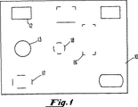
図1に示されているように、キャリア・シート10に転写された位置合わせの情報は、取り付けられる光硬化性要素の完全な輪郭(例えば12、13)、光硬化性要素の例えば隅、辺、または弧に対応する不完全な輪郭(それぞれ16、17および18参照)、或いは取り付け工程の際に要素を直接位置させるのに使用される他の適当な標識を含んでいることができる。
【0020】
図2に示されているように、本発明の複合印刷版11は、位置合わせの情報に従って、即ち印刷される輪郭および/または標識によって示される位置の所で光硬化性要素20をキャリア・シート10の一つの面の上に取り付けることによってつくることができる。光硬化性要素は当業界の専門家に公知の多くの方法の任意の一つを用いて取り付けることができる。該要素を取り付ける好適な方法は、両面接着テープまたは他の適当な接着材をキャリア・シート、光硬化性要素、或いはこの両方に被覆する方法を含んでいる。該要素は特定の精度で取り付ける必要はない。必要なことはただ、キャリア・シートの最終的に凸版印刷の画像が印刷される部分の上にだけ光硬化性要素を取り付けることである。
【0021】
本発明に従えば、光硬化性要素はそれが取り付けられるキャリア・シートの全表面積よりも少ない区域を被覆するようにすることができる。換言すれば、取り付けられた光硬化性要素は、その表面積を全部合わせても、キャリア・シートの面の表面積の100%よりも小さいことが好ましい。
【0022】
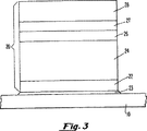
本発明で使用できる光硬化性要素は非常に多様な種類がある。好適具体化例においては、この要素は一体となっており、厚さが約0.01〜約0.35インチであり、寸法は最大約60〜約110インチである。図3に示されているように、好適な光硬化性要素20は支持層22、1枚またはそれ以上の光硬化性の層24、26、および除去可能なカバーシート28を含んでいる。このような光硬化性要素は随時、カバーシートと光硬化性の層との間にある透明な保護層27を含んでいる。キャリア・シート10の上に該要素20を取り付けるための接着材23も図3に示されている。
【0023】
図4に示されているように、光硬化性要素(例えば40および46)はそのそれぞれの主要面(即ち43と44、および48と49)の間に延びた横方向の面(即ち42と47)をもっている。これらの横方向の面は約90°(42および43の場合のように)またはそれよりも大きな角度(47および48の場合のように)をなして上方の主要面と交わることが好ましい。横方向の面42および47にテープ、インク、顔料、或いは要素20の中の光硬化性の材料を硬化させ得る少なくとも一つの波長領域の化学線に対して実質的に不透明な他の種類の材料を被覆することが好適である。このような材料を被覆すると、横方向の面を通って入って来る化学線に対し光硬化性の材料が望ましくない露光を受けることが防止されると考えられる。
【0024】
光硬化性要素の支持体または裏地層は透明または不透明な材料、例えば紙、セルロースフィルム、プラスティックスまたは金属からつくることができる。好適具体化例においては、この層は厚さが0.005インチ程度のポリエチレンテレフタレート・フィルムである。もっと確実に光硬化性の層に取り付けるために、随時支持体に接着剤を付けられていることができる。
【0025】
一般に厚さが約0.01〜0.35インチである光硬化性の層は種々の公知光硬化性重合体、反応開始剤、反応希釈剤、充填剤および染料を含んでいることができる。好適な光硬化性材料はエラストマー配合物、末端エチレン基を少なくとも1個有するエチレン型不飽和化合物、および光反応開始剤を含んでいる。光硬化性材料の例はヨーロッパ特許明細書0 456 336 A2(Goss等)および同0 640 878A1(Goss等)、英国特許1,366,769号および米国特許5,223,375号(Barrier等)、同3,867,153号(MacLahan)、同4,264,705号(Allen)、同4,265,986号(Allen)、同4,369,246号(Chen等)、同4,423,135号(Chen等)、および同3,265,765号(Holden等)、4,320,188号(Heinz等)、同4,427,759号(Gruetzmacher等)、同4,460,675号(Gruetzmacher等)、同4,622,088号(Min)、および同5,135,827号(Bohm等)に記載されている。これらの特許は参考のために添付されている。第2の光硬化性の層を使用する場合には、典型的にはこれを第1の層の上に同様な組成のものを配置するが、かなり薄いもの、通常は0.01インチよりも薄いものを用いる。
【0026】
本発明の光硬化性材料は少なくともある波長領域の化学線で交叉結合(硬化)させ、それによって硬化したものでなければならない。本明細書において化学線と云う言葉は露光された部分に化学変化を起こさせ得る光である。化学線には例えば増幅された光(例えばレーザー)および増幅されていない光、好ましくは紫外および赤外の波長領域の光が含まれる。好適な化学線の波長領域は約250nm〜約450nm、さらに好ましくは約300nm〜約400nm、それよりも好ましくは約320nm〜約380nmである。
【0027】
光硬化性要素の保護層はしばしばスリップフィルムと呼ばれ光硬化性の層の上に配置されるが、その厚さは典型的には約0.001〜約0.01インチである。保護層は光硬化性要素を汚染から保護し、取り扱いを容易にし、インク受容層として作用する。
【0028】
最後の層、即ちカバーシートはプラスティックス、または使用されるまで版を損傷から保護する任意の他の除去可能な材料からつくることができる。
【0029】
本発明の代表的な光硬化性要素はEPIC(R)、SPLASH(R)およびFLEXCOR(R)の商品名をもつフレキソ印刷版を含んでいる(米国ジョージア州AtlantaのPolyfibron Technologies,Inc.から市販されている)。
【0030】
キャリア・シートの上に取り付けられた少なくとも2枚の光硬化性要素の外側に向いた表面に、コンピュータ制御によりネガの画像を直接転写することにより複合版に対する位置合わせを行なうことができる。このようなネガの画像は光を遮蔽する材料を光硬化性要素の個々の表面に沈着させることによって転写することが好ましい。化学線に露光させさらに処理をした後に、光遮蔽材料の下になっていない版の部分が凸版印刷の画像を形成する。
【0031】
好適具体化例においては、ネガ生成用のインクをプリンター、例えばインクジェット・プリンターから複合版の上に放出させる。本発明には広範囲の種類のプリンターを用いることができる。適当なプリンターは印刷産業に使用される種々の大きさおよび形の複合版の上に明確に規定された画像を印刷できる(或いは印刷するようにした)プリンターである。明確度(分解能)のレベルは典型的にはドット/インチ(dpi)の単位で測定されるが、これはできるだけ大きくなければならない。本発明のプリンターによって送り出されるインクの量は、入射化学線の少なくとも約85%、好ましくは約90%、さらい好ましくは約95%、もっと好ましくは約99.9%を吸収するのに十分な量でなければならない。好適なプリンターは1回の印刷で完全に光を吸収する量のインクを送り出し得るプリンターであるが、或る種のプリンター(および或る種のインク)の場合には、光を吸収する量のインクを送り出すには多重印刷が必要なことがある。
【0032】
インクジェット・プリンターが特に好適である。インクジェット・プリンターによる印刷は、印刷ヘッドからインクの液滴を基質へ放出することによって行なわれる。この液滴は典型的には印刷ヘッドのオリフィスまたはノズルを通して放出され、基質の方へ向って動き画像を形成する。多くの他のタイプの印刷とは対照的にインクジェット印刷では通常プリンターと基質とは接触していない。本発明においては印刷ヘッドおよびそこからのインクの放出を制御しおよび/または方向を決める何らかの装置の両方が備えられている限り、実際上任意のインクジェット・プリンターを使用することができる。同様に制御信号に応答してインクの液滴を放出する少なくとも1個のノズルを含んでいる限り、実際上当業界に公知の任意の印刷ヘッドを使用することができる。図5を参照すれば多数のノズル32を有する印刷ヘッド30、および該印刷ヘッドに電気的に結合された制御装置34および36から成る本発明の代表的な印刷装置が示されている。制御装置は印刷基質に対して印刷ヘッドの位置を制御し、該印刷ヘッドを作動させ(即ちインク38を放出させ)得る当業界に公知の任意のものであることができる。本発明を実施するのに使用される制御装置は計算装置、例えばマイクロプロセッサー、マイクロコントローラ、蓄電器、スイッチ、回路、論理ゲート、または同等な論理装置を含んでいる。代表的な制御装置は印刷ヘッドのドライバーの基板に連結されたパーソナル・コンピュータを含んでいる。代表的なソフトウエア・パッケージはAdobe PhotoshopおよびCorel Drawの製品を含んでいる。代表的なインクジェット・プリンターはSpectra Incorporated,Dataproducts Corporation(米国カリフォルニア州Woodland Hills)、Jarfalls(スエーデン)、Encad(米国カリフォルニア州San Diego)、AlphaMerica(米国カリフォルニア州Simi Valley)、Videojet(米国イリノイ州Wood Dale)、特にEpson Stylus(米国カリフォルニア州Torrance、Epson Corporation)、HP 600c、HP 650c、HP 855c、およびHP 750cインクジェット・プリンター(米国カリフォルニア州Palo Alto、Hewlett−Packard Corp.)およびRaster Image Processor(米国ニューヨーク州Peekskill、Alan Graphics)により製造されたものを含んでいる。特に好適な印刷装置は米国ジョージア州AtlantaのPolyfibron Technologyから市販されているBOXCORTMシステムである。
【0033】
本発明に使用されるインクは上記の光硬化性要素を硬化させ得る少なくとも一つの波長領域における化学線に対して実質的に不透明であり、該波長領域の化学線に露光することにより起こる重合に対し実質的に抵抗性をもっている液体または固体の材料である。実質的に不透明なインクは入射した化学線の少なくとも約85%、好ましくは該化学線の90%、さらに好ましくは約95%、もっと好ましくは99.9%を吸収し得るインクである。実質的に不透明なインクは、基質の上に実質的に不透明にするのに十分な量だけ沈積し得る限り、すべての量およびすべての可能な濃度で不透明である必要はない。本発明に従えばインクは凸版印刷面を傷つけることなくそれが被覆される表面から除去される(好ましくは通常の版−洗滌法を使用して)限り、またそれを除去した場合凸版印刷面を傷つける程度に反応したり或いは他の方法で版の化学的および/または物理的性質を変化させることがない限り、重合に対して実質的に抵抗性をもっている。好適なインクは溶媒に好ましくは濃度約3〜約20重量%の濃度で溶解した、1種またはそれ以上の光を吸収する分子を含んでいる。特に好適なインクはU−26、U−53M、Black 4D、およびJoltの商標をもつもの(Dataproducts orporation)およびCrown Super Marking Stamping Ink(米国フィラデルフィア州Warminster、Fulton Marking Equipment Company)とUVINUL 3050の商品名の2,2’,4,4’−テトラヒドロキシベンゾフェノンとを、メタノール、イソプロパノール、n−ブタノール、クロロフォルム、メチルエチルケトン、プロピレングリコールモノメチルエーテル、ジプロピレングリコールモノメチルエーテル、ジエチレングリコールエチルエーテル、およびこれらの混合物から成る群から選ばれる溶媒に混合してつくられたものである。他の有用なインクの成分にはTinopal SPFおよびJoncryl 68製品であり、これらはそれぞれ米国ニューヨーク州HawthronのCiba−Geigy Corp.および米国ウィスコンシン州MilwaukeeのS.C.Johnson Companyから市販されている。
【0034】
本発明方法は光学的な装置または光学的なマスクを使用せずに光硬化性要素の表面にネガの画像を転写する方法を含んでいる。これは典型的には取り付けられた市販の光硬化性要素からカバーシートを取り外し、カバーシートを除去したことによって露出した表面上にネガの画像を印刷することによって達成される。光硬化性要素は最初正確に位置合わせされてカバーシートの上に載せられていないから、一般にネガと共に各要素の周囲の周りの「裁ちしろ」または「縁」の区域に印刷することが好ましい。この縁の部分は典型的には該要素の意図された外側の限界の所で始まり、光硬化性要素をキャリア・シートの上に載せた場合の不正確さのレベルに対応した或る選ばれた距離だけ外側へと延びている。当業界の専門家は、十分に大きな縁を使用して、ネガに従って硬化させることを意図された部分以外の外側にある光硬化性材料の硬化を防がなければならないことが判るであろう。
【0035】
ネガの画像を転写した後、これを(従って複合版の少なくとも一部を)適当な波長領域の化学線、好ましくは紫外線に露光する。光硬化性要素のこのいわゆる「前」露光を行なうのに使用できる装置は多数あり、FLEX−LIGHT(R)の商品名のUVモジュール(Polyfibron Technologies,Inc.)並びにAnderson & Vreeland(米国オハイオ州Bryan)およびPhotomeca(フランス、Pompeii)社製のものが含まれる。或る種の用途に対しては印刷機能と露光機能とを組み合わせて一つの装置にすることが望ましい。また支持体の近傍にある光硬化性材料の一部を硬化させるのに十分な時間の間硬化させる条件下に光硬化性要素の支持体を露出することによって「逆」露光を行なうことが望ましい。この逆露光は取り付け工程の後で行なうことができる(但しキャリア・シートおよび取り付け装置が化学線に対し十分に透明である限り)が、光硬化性材料を取り付ける前に行なう方が好適である。
【0036】
ネガの画像を化学線に対して前露光した後、典型的には光硬化性材料が少なくとも部分的に可溶な有機溶媒および/または水性溶媒を用い(および/またはその中で)光硬化性要素を洗滌することにより、取り付けられた光硬化性要素から未硬化の光硬化性重合体を除去する。典型的にはこの溶媒による洗滌工程の前または後でブラシ掛け、拭き取りまたはその他の温和な非破壊的な摩耗操作を要素に対して行なう。有用な洗滌装置にはPolyfibron Technologies、Anderson & Vreeland、およびPhotomecaの各社から市販されているものが含まれる。
【0037】
本発明の他の目的、利点および新規特徴は下記実施例を検討することにより当業界の専門家には明らかになるであろう。これらの実施例は本発明を限定するものではない。
【0038】
実施例 1
厚さ30ミルの36×38インチのポリエチレンテレフタレートのキャリア・シートをロールから切り取り、AlphaMerica社製のインクジェット・プロッターに取り付ける。Photoshopのソフトウエアを用いてコンピュータに保存された電子的な画像からキャリア・シートに取り付ける光硬化性要素の寸法的な輪郭を生成させた。上記プロッターおよび通常のインクを用い近似的な位置合わせを行なってキャリア・シートの上にこの輪郭を描かせた。
【0039】
それぞれの寸法をもつFLEXCORTM155光硬化性要素を切り取り、FLEX−LIGHT(R)5280露光装置(Polyfibron Technologies,Inc.)上において16秒間逆露光を行なう。ついでこれらの要素を個々の寸法の輪郭でキャリア・シートの上に取り付ける。キャリア・シートへの該要素の取り付けは両面接着テープを用いて行なった。
【0040】
取り付けた要素からカバーシートを取り外し、複合版をプロッターの中に入れる。保存したネガの画像をコンピュータからプロッターに送り、商品名U−53Mのインクを用い600DPIで版に印刷した。50μmのオリフィス・ヘッドから付着させたインクの厚さ(約1ミル)は次の硬化工程で使用される紫外線の約87%を遮蔽するのに十分であった。このソフトウエアは要素が取り付けられている区域にだけネガの画像を印刷することができる。インクジェット・プロッターを駆動するコンピュータにより非常に正確な位置合わせが得られた。
【0041】
次に画像が描かれた光硬化性要素が取り付けられたキャリアを商品名FLEX−LIGHT(R)露光器の中で15分間紫外線を浴びせて露光する。次に商品名FLEX−LIGHT(R)Processor5280、一連番号017のインライン・プロセッサーの中で6分間未硬化の重合体をブラシ掛けしながら、商品名SOLVITTMの溶媒(Polyfibron Technologies,Inc.)を連続的に供給することにより複合版の処理を行なった。この処理中両面接着テープは溶媒に抵抗性をもっている。キャリアを乾燥し、商品名FLEX−LIGHT(R)のDryer5280、一連番号017の乾燥機中で後露光を行なった。
【0042】
ネガの画像が印刷された要素を有するキャリアを次に周が36インチのドラムに取り付ける。この際要素は既に位置合わせが行なわれている。ネガの凸版印刷面に通常の印刷インクを塗り、この表面を紙のシートに接触させて高品質のポジの画像を得た。
【0043】
当業界の専門家は、本発明の好適具体化例に対し多くの変更および変形を行なうことができ、このような変形および変更は本発明の精神を逸脱することなく行ない得ることを理解できるであろう。従って添付特許請求の範囲は本発明の真の精神および範囲に入るこのようなすべての同等物を包含するものとする。
【図面の簡単な説明】
【図1】 位置合わせ情報を有するキャリア・シートの上面図。
【図2】 本発明の複合印刷版の上面図。
【図3】 本発明の複合印刷版の断面図。
【図4】 本発明の複合印刷版の断面図。
【図5】 複合印刷版に対する印刷装置の平面図。[0001]
[Related Applications]
This application is a continuation-in-part of US patent application Ser. No. 08 / 676,591, filed Jul. 8, 1996. The patent application is attached for reference.
[0002]
(Field of the Invention)
The present invention relates to a method for making a plate for composite printing, and more particularly to a method for directly transferring a digital image to such a composite printing plate without using an optical device or an optical mask.
[0003]
(Background of the present invention)
In both flexographic and letterpress printing, relief printing plates of images are used to print on a variety of substrates including paper, corrugated paper, films, foils, and laminates. The photocurable element used to make a relief printing plate typically comprises a support layer and one or more layers of photocurable polymer in the form of an integrated sheet. . The printer typically peels the cover sheet from this element to expose the photocurable polymer and places a silver halide photographic negative or other mask device on top of the photosensitive polymer. The photocurable polymer carrying the negative is exposed to ultraviolet (UV) through the negative to cure the exposed areas of the element. After removing the unexposed areas of the element, the cured polymer remains as a relief printing surface.
[0004]
Cardboard boxes or other relatively large objects, such as those printed using a relief printing plate of images, are often actually printed on only a small portion of their total surface area. One method for printing on such an object is to make a single relief printing plate for image printing having a surface area corresponding to the total surface area of the object. However, since only a part of the surface area of the object needs to be printed, only a part of the relief printing plate for image printing is used for actual ink transfer. The rest of the plate remains unused and is essentially wasted.
[0005]
To minimize such waste, experts in the industry use relatively large objects using composite printing plates made by mounting multiple image relief printing plates on a common carrier sheet. Many things are printed. However, the individual plates are only mounted on the part of the carrier corresponding to the part of the object that actually needs to be printed. Although such a composite plate minimizes waste, the current system for attaching the components of the relief printing plate for images is complicated, and it is necessary to perform high-precision printing and reproduce multicolor printing. Requires careful adhesion of the plate to the carrier so that the image can be aligned within 0.005 inches during printing. In a multicolor reproduction method in which printing is performed using one plate for each individual color, it is extremely important to accurately register the plates with each other.
[0006]
Accordingly, there remains a need in the industry for alternative methods of making composite printing plates. In particular, there is still a need for a method for accurately aligning the components of a relief printing plate or for a method that does not require accurate alignment.
[0007]
(Object of the present invention)
An object of the present invention is to provide a method of making a composite printing plate.
[0008]
Another object of the present invention is to provide a method for aligning at least one relief image printing plate on a common carrier sheet.
[0009]
Yet another object of the present invention is to provide a method for printing registration information directly on the surface of a carrier sheet using a computer.
[0010]
It is yet another object of the present invention to provide a method for transferring an electronically stored negative image directly onto a composite printing plate.
[0011]
(Brief description of the present invention)
These and other objects of the present invention are achieved by providing a method for making a high quality composite printing plate that does not require individual registration of the components of the relief image printing plate according to the present invention. These methods comprise the steps of placing a photocurable element with approximate alignment on the surface of a substantially flat carrier sheet and then transferring a computer generated negative to the element. . In a preferred embodiment, the method of the present invention produces at least two substantially flat photocurable elements having first and second opposing major surfaces with defined surface areas, the photocuring A first surface of the sex element is disposed on a first surface of a substantially flat carrier sheet having first and second opposing major surfaces with a defined surface area, from the inkjet printhead. And releasing the ink that produces a negative on the second side of the photocurable element.
[0012]
Approximate alignment of the photocurable element is accomplished by transferring computer generated alignment information onto the carrier sheet. This can be done, for example, by transferring some visually perceptible material (e.g. ink from an inkjet printhead) onto the sheet, scoring or otherwise deforming the sheet. The registration information comprises, for example, a series of images in which each shape corresponds to the contour of each photocurable plate. After transferring the alignment information, the photocurable element is placed on the carrier sheet according to the position specified by the alignment information.
[0013]
In order to transfer the negative generated by the computer to the composite plate of the present invention, it is preferable to discharge the negative generating ink from the ink jet printing head. The ink is substantially opaque to at least one wavelength region of actinic radiation capable of curing the photocurable material inside the photocurable element, and when exposed to actinic radiation in the wavelength region It is preferably substantially resistant to the polymerization that occurs. After the step of transferring the negative, the inked plate was exposed under conditions that allowed curing to occur for a time sufficient to cure the exposed areas of the photocurable material, and then not exposed (ie The area that is not hardened) can be removed to create a relief printing surface.
[0014]
The present invention further provides a composite printing plate that produces a negative made by the above method. In some embodiments, the plate comprises a number of photocurable elements disposed on a substantially flat carrier sheet, wherein at least two of the photocurable elements are a support layer, the support layer. A photocurable material disposed on the substrate and a negative generating ink disposed on at least a portion of the surface of the photocurable material.
[0015]
Many objects and advantages of this invention will be readily appreciated by those skilled in the art by reference to the accompanying drawings. In these drawings, the dimensional proportions are not drawn accurately.
[0016]
(Detailed Description of the Invention)
The present invention provides a method that does not require the cumbersome task of manually aligning the individual relief printing plates when producing high quality composite printing plates. The method of the present invention can be used to make printing plates of any size, but is particularly useful for making relatively large printing plates (ie, lengths and / or widths of about 30 inches or more). . In the method of the present invention, a photocurable element having the appropriate size required (or slightly larger than required) is positioned in an approximate position relative to the final printed area. Align and place on the carrier sheet. In this case, accurate “alignment” of the elements is achieved by adding a computer generated negative image to the composite printing plate by means of an ink jet printer.
[0017]
The composite printing plate of the present invention is preferably prepared by first transferring registration information generated by a computer to one side of a suitable carrier sheet. The carrier sheet must be substantially flat (ie, its length and width are substantially greater than its thickness, preferably at least 10 times, with two substantially flat opposing major surfaces. Can be made of transparent or opaque materials such as paper, cellulose film, plastics or metal. In a preferred embodiment, the carrier sheet is a polyethylene terephthalate film having a thickness of 0.004 to 0.050 inches.
[0018]
Transferring the registration information according to the present invention includes applying any visually perceptible deformation to the carrier sheet to reflect the position of the photocurable element. Registration information can be transferred, for example, by placing a visually perceptible material on the carrier sheet. Exemplary materials are sensitive to the human eye, for example by exposure to light of a selected wavelength (eg in the case of fluorescent dyes) and / or by contact with chemicals (eg in the case of diazo dyes) and / or Contains various inks, dyes, and pigments known in the art that can be felt. These materials can be placed using conventional methods such as inkjet and bubble jet printers and pens and ink blotting paper. Further, the alignment information can be transferred to the carrier sheet without using any visually perceptible material by deforming the carrier sheet by some means for visually perceiving it. The carrier sheet can be “scored” by some deformation, for example using a knife, razor blade, or other suitable means of applying pressure. Further, for example, a laser can be used to shine on the carrier sheet. Further, alignment information can be projected onto the carrier sheet using, for example, a transparent material, a slide or a digital LCD projector.
[0019]
As shown in FIG. 1, the registration information transferred to the
[0020]
As shown in FIG. 2, the composite printing plate 11 of the present invention allows the
[0021]
In accordance with the present invention, the photocurable element can cover an area that is less than the total surface area of the carrier sheet to which it is attached. In other words, the attached photocurable element is preferably less than 100% of the surface area of the surface of the carrier sheet, even if all the surface areas are combined.
[0022]
There are a wide variety of photocurable elements that can be used in the present invention. In a preferred embodiment, the elements are unitary, have a thickness of about 0.01 to about 0.35 inches, and dimensions up to about 60 to about 110 inches. As shown in FIG. 3, a suitable
[0023]
As shown in FIG. 4, the light curable elements (eg, 40 and 46) have lateral faces (ie, 42 and 42) extending between their respective major faces (ie, 43 and 44, and 48 and 49). 47). These lateral surfaces preferably meet the upper major surface at an angle of about 90 ° (as in 42 and 43) or greater (as in 47 and 48). Other types of material that is substantially opaque to actinic radiation in at least one wavelength region that can cure the lateral surfaces 42 and 47 with tape, ink, pigment, or photocurable material in
[0024]
The support or backing layer of the photocurable element can be made from a transparent or opaque material such as paper, cellulose film, plastics or metal. In a preferred embodiment, this layer is a polyethylene terephthalate film having a thickness on the order of 0.005 inches. An adhesive can be applied to the support from time to time to more securely attach to the photocurable layer.
[0025]
The photocurable layer, generally about 0.01 to 0.35 inches in thickness, can contain various known photocurable polymers, reaction initiators, reaction diluents, fillers and dyes. Suitable photocurable materials include an elastomeric blend, an ethylenically unsaturated compound having at least one terminal ethylene group, and a photoinitiator. Examples of photocurable materials are European patent specifications 0 456 336 A2 (Goss et al.) And 0 640 878A1 (Goss et al.), British Patent 1,366,769 and US Pat. No. 5,223,375 (Barrier et al.). 3,867,153 (MacLahan), 4,264,705 (Allen), 4,265,986 (Allen), 4,369,246 (Chen et al.), 4,423 , 135 (Chen et al.), And 3,265,765 (Holden et al.), 4,320,188 (Heinz et al.), 4,427,759 (Grutzmacher et al.), 4,460,675. No. (Gruetzmacher et al.), No. 4,622,088 (Min), and No. 5,135,827 (Bohm et al.) It has been described. These patents are attached for reference. If a second photocurable layer is used, it is typically placed on the first layer with a similar composition, but is much thinner, usually less than 0.01 inches. Use a thin one.
[0026]
The photo-curable material of the present invention must be cross-linked (cured) with actinic radiation in at least a certain wavelength region and cured thereby. As used herein, the term actinic radiation is light that can cause a chemical change in an exposed area. Actinic radiation includes, for example, amplified light (eg, laser) and unamplified light, preferably light in the ultraviolet and infrared wavelength regions. A suitable wavelength range of actinic radiation is about 250 nm to about 450 nm, more preferably about 300 nm to about 400 nm, and more preferably about 320 nm to about 380 nm.
[0027]
The protective layer of the photocurable element, often referred to as a slip film, is disposed on the photocurable layer, but its thickness is typically from about 0.001 to about 0.01 inches. The protective layer protects the photocurable element from contamination, facilitates handling, and acts as an ink receiving layer.
[0028]
The last layer, i.e. the cover sheet, can be made of plastic or any other removable material that protects the plate from damage until it is used.
[0029]
A typical photocurable element of the present invention is EPIC. (R) , SPLASH (R) And FLEXCOR (R) (Commercially available from Polyfibron Technologies, Inc. of Atlanta, Georgia, USA).
[0030]
Registration to the composite plate can be accomplished by direct computer controlled transfer of the negative image to the outwardly facing surface of at least two photocurable elements mounted on the carrier sheet. Such negative images are preferably transferred by depositing a light blocking material on the individual surfaces of the photocurable element. After exposure to actinic radiation and further processing, the portion of the plate that is not under the light shielding material forms a relief printing image.
[0031]
In a preferred embodiment, the negative generating ink is discharged from a printer, such as an ink jet printer, onto the composite plate. A wide variety of printers can be used in the present invention. A suitable printer is a printer capable of printing (or adapted to print) clearly defined images on composite plates of various sizes and shapes used in the printing industry. The level of clarity (resolution) is typically measured in units of dots per inch (dpi), but this should be as large as possible. The amount of ink delivered by the printer of the present invention is sufficient to absorb at least about 85%, preferably about 90%, more preferably about 95%, more preferably about 99.9% of the incident actinic radiation. Must. A suitable printer is one that can deliver an amount of ink that completely absorbs light in a single print, but in the case of certain printers (and certain inks) Multiple printing may be required to deliver ink.
[0032]
Inkjet printers are particularly suitable. Printing by an inkjet printer is performed by ejecting ink droplets from a print head onto a substrate. The droplets are typically ejected through the orifices or nozzles of the print head and move toward the substrate to form an image. In contrast to many other types of printing, inkjet printing usually does not contact the printer and substrate. Any ink jet printer can be used in the present invention as long as both the print head and any device that controls and / or directs ink ejection therefrom are provided. Similarly, virtually any print head known in the art can be used as long as it includes at least one nozzle that ejects ink droplets in response to a control signal. Referring to FIG. 5, there is shown a representative printing apparatus of the present invention comprising a
[0033]
The ink used in the present invention is substantially opaque to actinic radiation in at least one wavelength region capable of curing the above-described photocurable element, and undergoes polymerization caused by exposure to actinic radiation in the wavelength region. It is a liquid or solid material that is substantially resistant to it. A substantially opaque ink is an ink that can absorb at least about 85% of the incident actinic radiation, preferably 90% of the actinic radiation, more preferably about 95%, more preferably 99.9%. The substantially opaque ink need not be opaque in all amounts and in all possible concentrations as long as it can be deposited on the substrate in an amount sufficient to make it substantially opaque. In accordance with the present invention, the ink is removed from the surface to which it is coated without damaging the relief printing surface (preferably using conventional plate-washing methods), and if removed, the relief printing surface is removed. Unless it reacts to the extent of damage or otherwise alters the chemical and / or physical properties of the plate, it is substantially resistant to polymerization. Suitable inks contain one or more light absorbing molecules dissolved in a solvent, preferably at a concentration of about 3 to about 20% by weight. Particularly preferred inks are U-26, U-53M, Black 4D, and Jolt trademarked (Dataproducts Corporation) and Crown Super Marking Stamping Ink (Products in Warminster, Philadelphia, USA) The name 2,2 ′, 4,4′-tetrahydroxybenzophenone from methanol, isopropanol, n-butanol, chloroform, methyl ethyl ketone, propylene glycol monomethyl ether, dipropylene glycol monomethyl ether, diethylene glycol ethyl ether, and mixtures thereof Made with a solvent selected from the group consisting of That. Other useful ink components are the Tinopal SPF and Joncryl 68 products, each of which is available from Ciba-Geigy Corp. of Hawthron, NY, USA. And S. of Milwaukee, Wisconsin, USA. C. It is commercially available from the Johnson Company.
[0034]
The method includes a method of transferring a negative image to the surface of the photocurable element without the use of an optical device or optical mask. This is typically accomplished by removing the cover sheet from the attached commercial photocurable element and printing a negative image on the surface exposed by removing the cover sheet. Since the photocurable elements are not initially accurately aligned and placed on the cover sheet, it is generally preferred to print with negatives in the "border" or "edge" area around the periphery of each element. This edge portion typically begins at the intended outer limit of the element and is chosen to correspond to a level of inaccuracy when the photocurable element is placed on a carrier sheet. For a certain distance. Those skilled in the art will recognize that a sufficiently large edge must be used to prevent curing of the photocurable material outside of the part other than the part intended to be cured according to the negative.
[0035]
After the negative image has been transferred, it (and thus at least a portion of the composite plate) is exposed to actinic radiation in the appropriate wavelength region, preferably ultraviolet light. There are a number of devices that can be used to perform this so-called “pre” exposure of the photocurable element, FLEX-LIGHT. (R) As well as those manufactured by Anderson & Vreland (Bryan, Ohio, USA) and Photomeca (Pompeii, France) under the trade name UV modules (Polyfibron Technologies, Inc.). For certain applications, it is desirable to combine a printing function and an exposure function into a single device. It is also desirable to perform "back" exposure by exposing the support of the photocurable element under conditions that cure for a time sufficient to cure a portion of the photocurable material in the vicinity of the support. . This back-exposure can be done after the attachment process (as long as the carrier sheet and attachment device are sufficiently transparent to actinic radiation), but it is preferred to do it before attaching the photocurable material.
[0036]
After the negative image is pre-exposed to actinic radiation, it is typically photocurable using (and / or in) organic and / or aqueous solvents in which the photocurable material is at least partially soluble. The element is washed to remove uncured photocurable polymer from the attached photocurable element. Typically, the element is subjected to brushing, wiping or other mild non-destructive wear operations before or after the solvent washing step. Useful cleaning devices include those commercially available from Polyfibron Technologies, Anderson & Vreland, and Photomeca.
[0037]
Other objects, advantages and novel features of the invention will become apparent to those skilled in the art upon review of the following examples. These examples do not limit the invention.
[0038]
Example 1
A 30 mil thick 36 × 38 inch polyethylene terephthalate carrier sheet is cut from the roll and mounted on an AlphaMerica inkjet plotter. Photoshop software was used to generate a dimensional profile of the photocurable element to be attached to the carrier sheet from an electronic image stored on a computer. This contour was drawn on the carrier sheet using approximate alignment using the plotter and normal ink.
[0039]
FLEXCOR with each dimension TM Cut out 155 photocurable element, FLEX-LIGHT (R) Back exposure is performed for 16 seconds on a 5280 exposure apparatus (Polyfibron Technologies, Inc.). These elements are then mounted on the carrier sheet with contours of individual dimensions. The element was attached to the carrier sheet using double-sided adhesive tape.
[0040]
Remove the cover sheet from the attached element and place the composite plate in the plotter. The stored negative image was sent from the computer to the plotter and printed on the plate at 600 DPI using the ink of trade name U-53M. The thickness of ink deposited from the 50 μm orifice head (about 1 mil) was sufficient to block about 87% of the ultraviolet light used in the next curing step. The software can print negative images only in areas where elements are attached. A very accurate alignment was obtained by the computer driving the inkjet plotter.
[0041]
Next, the carrier on which the photo-curable element on which the image is drawn is attached is trade name FLEX-LIGHT. (R) Exposure is performed by exposing to ultraviolet rays for 15 minutes in an exposure unit. Next, trade name FLEX-LIGHT (R) Processor 5280, brand number SOLVIT while brushing uncured polymer for 6 minutes in inline processor with serial number 017 TM The composite plate was processed by continuously supplying a solvent (Polyfibron Technologies, Inc.). During this process, the double-sided adhesive tape is resistant to solvents. Dried carrier, trade name FLEX-LIGHT (R) Of Dryer 5280, serial number 017.
[0042]
The carrier having the element with the negative image printed thereon is then attached to a 36 inch circumference drum. At this time, the elements have already been aligned. Ordinary printing ink was applied to the negative relief printing surface, and this surface was brought into contact with a paper sheet to obtain a high-quality positive image.
[0043]
Those skilled in the art will appreciate that many changes and modifications can be made to the preferred embodiment of the present invention and that such modifications and changes can be made without departing from the spirit of the invention. I will. Accordingly, the appended claims are intended to embrace all such equivalents that fall within the true spirit and scope of this invention.
[Brief description of the drawings]
FIG. 1 is a top view of a carrier sheet having alignment information.
FIG. 2 is a top view of the composite printing plate of the present invention.
FIG. 3 is a cross-sectional view of the composite printing plate of the present invention.
FIG. 4 is a cross-sectional view of the composite printing plate of the present invention.
FIG. 5 is a plan view of a printing apparatus for a composite printing plate.
Claims (37)
該位置合わせ情報を有する該キャリア・シートの上に規定された表面積をもった第1および第2の相対する主要面を有する少なくとも一つの光硬化性要素の第1の面を配置し、ただし該光硬化性要素の該第2の面は光硬化性材料の層の上に配置された透明な保護層である、
インクジェット印刷ヘッドから該光硬化性要素の該第2の面の上にネガを生成するインクを放出させる工程から成り、
この際該インクは該要素の内部の光硬化性材料を硬化させる効果をもつ少なくとも一つの波長領域における化学線に対して実質的に不透明であり、また該波長領域における化学線に露光することによって起こる重合に対して実質的に抵抗性をもっていることを特徴とする複合印刷版の製作法。Transferring alignment information onto a first surface of a carrier sheet having first and second opposing major surfaces with a defined surface area;
Placing a first surface of at least one photocurable element having first and second opposing major surfaces with a defined surface area on the carrier sheet having the alignment information, wherein The second side of the photocurable element is a transparent protective layer disposed over the layer of photocurable material;
Discharging an ink that produces a negative on the second side of the photocurable element from an inkjet printhead;
In this case, the ink is substantially opaque to actinic radiation in at least one wavelength region having the effect of curing the photocurable material inside the element, and is exposed to actinic radiation in the wavelength region. A method of making a composite printing plate characterized by being substantially resistant to the polymerization that occurs.
該キャリア・シートの上に規定された表面積をもった第1および第2の相対する主要面を有する少なくとも一つの光硬化性要素の第1の面を配置し、この際該光硬化性要素は該第1および第2の面の間に横方向の面をもっており、
該光硬化性要素の内部の光硬化性材料を硬化させる効果をもつ少なくとも一つの波長領域における化学線に対して実質的に不透明であり且つ該波長領域における化学線に露光することによって起こる重合に対して実質的に抵抗性をもっている材料を該横方向の面に被覆し、
インクジェット印刷ヘッドから該光硬化性要素の該第2の面の上にネガを生成するイン
クを放出させ、この際該インクは該要素の内部の光硬化性材料を硬化させる効果をもつ少なくとも一つの波長領域における化学線に対して実質的に透明であり、また該波長領域における化学線に露光することによって起こる重合に対して実質的に抵抗性をもっているインクである工程から成ることを特徴とする複合印刷版の製作法。Creating a carrier sheet having first and second opposing major surfaces with a defined surface area;
Disposing a first surface of at least one photocurable element having first and second opposing major surfaces with a defined surface area on the carrier sheet, wherein the photocurable element comprises: Having a lateral surface between the first and second surfaces;
Polymerization that occurs by exposure to actinic radiation in the wavelength region that is substantially opaque to actinic radiation in at least one wavelength region and has the effect of curing the photocurable material inside the photocurable element. Coating the lateral surface with a material that is substantially resistant to,
An ink that produces a negative on the second side of the photocurable element is ejected from an ink jet printhead, wherein the ink has the effect of curing the photocurable material inside the element. Characterized in that it comprises a step that is an ink that is substantially transparent to actinic radiation in the wavelength region and that is substantially resistant to polymerization caused by exposure to actinic radiation in the wavelength region. How to make a composite printing plate.
支持層;
該支持層の上に配置された光硬化性材料;
該光硬化性材料の上に配置されたネガを生成するインク;および
該インクと光硬化性材料との間で該光硬化性材料の上に配置された透明な保護層を含み、
該インクは該光硬化性材料を硬化させる効果をもつ少なくとも一つの波長領域における化学線に対し実質的に不透明であり、また該波長領域の化学線に露光した際に起こる重合に対して実質的に抵抗性をもっていることを特徴とする複合印刷版。Comprising at least one photocurable element disposed on the first side of the carrier sheet having alignment information, the photocurable element comprising a support layer;
A photocurable material disposed on the support layer ;
An ink that produces a negative disposed on the photocurable material ; and
A transparent protective layer disposed on the photocurable material between the ink and the photocurable material,
The ink is substantially opaque to actinic radiation in at least one wavelength region that has the effect of curing the photocurable material, and is substantially free of polymerization that occurs upon exposure to actinic radiation in the wavelength region. A composite printing plate characterized by having resistance to
Applications Claiming Priority (3)
| Application Number | Priority Date | Filing Date | Title |
|---|---|---|---|
| US08/957,165 | 1997-10-24 | ||
| US08/957,165 US6312871B1 (en) | 1996-07-08 | 1997-10-24 | Composite relief image printing plates |
| PCT/US1998/022536 WO1999022273A1 (en) | 1997-10-24 | 1998-10-23 | Composite relief image printing plates |
Publications (3)
| Publication Number | Publication Date |
|---|---|
| JP2001521208A JP2001521208A (en) | 2001-11-06 |
| JP2001521208A5 JP2001521208A5 (en) | 2006-01-05 |
| JP4169476B2 true JP4169476B2 (en) | 2008-10-22 |
Family
ID=25499171
Family Applications (1)
| Application Number | Title | Priority Date | Filing Date |
|---|---|---|---|
| JP2000518307A Expired - Fee Related JP4169476B2 (en) | 1997-10-24 | 1998-10-23 | Composite printing plate for letterpress printing of images |
Country Status (11)
| Country | Link |
|---|---|
| EP (1) | EP1025464B1 (en) |
| JP (1) | JP4169476B2 (en) |
| KR (1) | KR20010031271A (en) |
| CN (1) | CN1214289C (en) |
| AT (1) | ATE332519T1 (en) |
| AU (1) | AU1119499A (en) |
| BR (1) | BR9814828A (en) |
| CA (1) | CA2308757C (en) |
| DE (1) | DE69835160T2 (en) |
| ES (1) | ES2268796T3 (en) |
| WO (1) | WO1999022273A1 (en) |
Families Citing this family (7)
| Publication number | Priority date | Publication date | Assignee | Title |
|---|---|---|---|---|
| US6312872B1 (en) * | 1997-10-24 | 2001-11-06 | Macdermid Graphic Arts | Composite relief image printing plates |
| JP2006113310A (en) * | 2004-10-15 | 2006-04-27 | Union Chemicar Co Ltd | Flexographic printing plate and plate making method |
| JP5463649B2 (en) * | 2008-10-27 | 2014-04-09 | 独立行政法人 国立印刷局 | Gradation resin plate and printed matter using gradation resin plate |
| JP5119191B2 (en) * | 2009-03-31 | 2013-01-16 | 富士フイルム株式会社 | Printing plate mounting apparatus and printing plate mounting method |
| US9375916B2 (en) * | 2010-06-18 | 2016-06-28 | Esko-Graphics Imaging Gmbh | Non-printing registration marks on a printing plate |
| US9618847B2 (en) * | 2014-02-20 | 2017-04-11 | E I Du Pont De Nemours And Company | Composite printing form precursor and method for preparing a printing form precursor for treatment |
| WO2022026847A1 (en) * | 2020-07-31 | 2022-02-03 | Digimarc Corporation | Encoding signals on flexographic printing plates to enable tracking and management |
Family Cites Families (13)
| Publication number | Priority date | Publication date | Assignee | Title |
|---|---|---|---|---|
| US2111914A (en) * | 1935-05-03 | 1938-03-22 | Hearst Entpr Inc | Registering device for use in making printing plates |
| CA1099435A (en) * | 1971-04-01 | 1981-04-14 | Gwendyline Y. Y. T. Chen | Photosensitive block copolymer composition and elements |
| US4265986A (en) * | 1979-11-21 | 1981-05-05 | Uniroyal, Inc. | Photopolymerizable composition containing chlorosulfonated polyethylene |
| JP2542501B2 (en) * | 1986-10-27 | 1996-10-09 | キヤノン株式会社 | Plate making method |
| DE3736180A1 (en) * | 1987-10-26 | 1989-05-03 | Basf Ag | METHOD FOR CLOSING AND / OR SEALING OPENINGS, CAVES OR SPACES IN PRINTING PLATES APPLIED ON FORM CYLINDERS |
| TR24835A (en) * | 1990-07-07 | 1992-05-01 | Thomson Brandt Gmbh | TELEVISION TRANSFER SYSTEM |
| DE4117127A1 (en) * | 1991-05-25 | 1992-11-26 | Basf Ag | Light-sensitive recording element with mask formed directly on top coat - comprising tear-resistant polymer, used as resist or esp. in computer to plate process |
| JPH05230408A (en) * | 1992-02-25 | 1993-09-07 | Seiko Epson Corp | Water-base recording ink composition and method for recording therewith |
| JP2837028B2 (en) * | 1992-06-26 | 1998-12-14 | 富士写真フイルム株式会社 | Automatic printing method |
| JPH06250372A (en) * | 1993-03-01 | 1994-09-09 | Miura Insatsu Kk | Device for editing block copy of notebook |
| GB2281250B (en) * | 1993-08-28 | 1997-10-08 | Flexographic Services Limited | A method of mounting a printing plate on a mounting sheet |
| AU1571997A (en) * | 1996-01-05 | 1997-08-01 | Polyfibron Technologies, Inc. | Methods and apparatus for preparing relief image printing plates |
| US5846691A (en) * | 1996-07-08 | 1998-12-08 | Polyfibron Technologies, Inc. | Composite relief image printing plates and methods for preparing same |
-
1998
- 1998-10-23 ES ES98953954T patent/ES2268796T3/en not_active Expired - Lifetime
- 1998-10-23 KR KR1020007004258A patent/KR20010031271A/en not_active Application Discontinuation
- 1998-10-23 BR BR9814828-1A patent/BR9814828A/en not_active Application Discontinuation
- 1998-10-23 CN CNB988104830A patent/CN1214289C/en not_active Expired - Fee Related
- 1998-10-23 DE DE69835160T patent/DE69835160T2/en not_active Expired - Lifetime
- 1998-10-23 AU AU11194/99A patent/AU1119499A/en not_active Abandoned
- 1998-10-23 EP EP98953954A patent/EP1025464B1/en not_active Expired - Lifetime
- 1998-10-23 WO PCT/US1998/022536 patent/WO1999022273A1/en active IP Right Grant
- 1998-10-23 JP JP2000518307A patent/JP4169476B2/en not_active Expired - Fee Related
- 1998-10-23 CA CA002308757A patent/CA2308757C/en not_active Expired - Fee Related
- 1998-10-23 AT AT98953954T patent/ATE332519T1/en not_active IP Right Cessation
Also Published As
| Publication number | Publication date |
|---|---|
| CN1214289C (en) | 2005-08-10 |
| CA2308757C (en) | 2008-01-08 |
| AU1119499A (en) | 1999-05-17 |
| BR9814828A (en) | 2000-10-03 |
| ES2268796T3 (en) | 2007-03-16 |
| EP1025464A1 (en) | 2000-08-09 |
| DE69835160D1 (en) | 2006-08-17 |
| JP2001521208A (en) | 2001-11-06 |
| ATE332519T1 (en) | 2006-07-15 |
| WO1999022273A1 (en) | 1999-05-06 |
| KR20010031271A (en) | 2001-04-16 |
| CA2308757A1 (en) | 1999-05-06 |
| DE69835160T2 (en) | 2007-07-12 |
| CN1277681A (en) | 2000-12-20 |
| EP1025464B1 (en) | 2006-07-05 |
| EP1025464A4 (en) | 2003-02-05 |
Similar Documents
| Publication | Publication Date | Title |
|---|---|---|
| US6312871B1 (en) | Composite relief image printing plates | |
| US6472121B2 (en) | Composite relief image printing elements | |
| JP3856697B2 (en) | Method for producing flexographic printing plate | |
| EP1737676A2 (en) | Edge cure prevention process | |
| JP4169476B2 (en) | Composite printing plate for letterpress printing of images | |
| WO1997025206A1 (en) | Methods and apparatus for preparing relief image printing plates | |
| JP7457831B2 (en) | How to Make a Film Negative | |
| MXPA00003672A (en) | Composite relief image printing plates | |
| JP7256885B2 (en) | Photopolymer film with UV filtering | |
| MXPA99000388A (en) | Composite plates of printing of image of relieve and methods to prepare the mis | |
| JPH08110633A (en) | Image forming method of printing paper |
Legal Events
| Date | Code | Title | Description |
|---|---|---|---|
| A521 | Request for written amendment filed |
Free format text: JAPANESE INTERMEDIATE CODE: A523 Effective date: 20050829 |
|
| A621 | Written request for application examination |
Free format text: JAPANESE INTERMEDIATE CODE: A621 Effective date: 20050829 |
|
| A131 | Notification of reasons for refusal |
Free format text: JAPANESE INTERMEDIATE CODE: A131 Effective date: 20080401 |
|
| A521 | Request for written amendment filed |
Free format text: JAPANESE INTERMEDIATE CODE: A523 Effective date: 20080626 |
|
| TRDD | Decision of grant or rejection written | ||
| A01 | Written decision to grant a patent or to grant a registration (utility model) |
Free format text: JAPANESE INTERMEDIATE CODE: A01 Effective date: 20080729 |
|
| A01 | Written decision to grant a patent or to grant a registration (utility model) |
Free format text: JAPANESE INTERMEDIATE CODE: A01 |
|
| A61 | First payment of annual fees (during grant procedure) |
Free format text: JAPANESE INTERMEDIATE CODE: A61 Effective date: 20080805 |
|
| FPAY | Renewal fee payment (event date is renewal date of database) |
Free format text: PAYMENT UNTIL: 20110815 Year of fee payment: 3 |
|
| R150 | Certificate of patent or registration of utility model |
Free format text: JAPANESE INTERMEDIATE CODE: R150 |
|
| FPAY | Renewal fee payment (event date is renewal date of database) |
Free format text: PAYMENT UNTIL: 20110815 Year of fee payment: 3 |
|
| S531 | Written request for registration of change of domicile |
Free format text: JAPANESE INTERMEDIATE CODE: R313531 |
|
| S533 | Written request for registration of change of name |
Free format text: JAPANESE INTERMEDIATE CODE: R313533 |
|
| FPAY | Renewal fee payment (event date is renewal date of database) |
Free format text: PAYMENT UNTIL: 20110815 Year of fee payment: 3 |
|
| R350 | Written notification of registration of transfer |
Free format text: JAPANESE INTERMEDIATE CODE: R350 |
|
| RD02 | Notification of acceptance of power of attorney |
Free format text: JAPANESE INTERMEDIATE CODE: A7422 Effective date: 20081009 |
|
| A521 | Request for written amendment filed |
Free format text: JAPANESE INTERMEDIATE CODE: A821 Effective date: 20081009 |
|
| A072 | Dismissal of procedure [no reply to invitation to correct request for examination] |
Free format text: JAPANESE INTERMEDIATE CODE: A072 Effective date: 20090303 |
|
| FPAY | Renewal fee payment (event date is renewal date of database) |
Free format text: PAYMENT UNTIL: 20110815 Year of fee payment: 3 |
|
| FPAY | Renewal fee payment (event date is renewal date of database) |
Free format text: PAYMENT UNTIL: 20120815 Year of fee payment: 4 |
|
| LAPS | Cancellation because of no payment of annual fees |