JP4169441B2 - Channel insertion and branching method and optical wavelength division multiplexing transmission system - Google Patents
Channel insertion and branching method and optical wavelength division multiplexing transmission system Download PDFInfo
- Publication number
- JP4169441B2 JP4169441B2 JP28912999A JP28912999A JP4169441B2 JP 4169441 B2 JP4169441 B2 JP 4169441B2 JP 28912999 A JP28912999 A JP 28912999A JP 28912999 A JP28912999 A JP 28912999A JP 4169441 B2 JP4169441 B2 JP 4169441B2
- Authority
- JP
- Japan
- Prior art keywords
- group
- multiplex
- parallel
- branch
- channel
- Prior art date
- Legal status (The legal status is an assumption and is not a legal conclusion. Google has not performed a legal analysis and makes no representation as to the accuracy of the status listed.)
- Expired - Fee Related
Links
Images


Classifications
-
- H—ELECTRICITY
- H04—ELECTRIC COMMUNICATION TECHNIQUE
- H04J—MULTIPLEX COMMUNICATION
- H04J14/00—Optical multiplex systems
- H04J14/02—Wavelength-division multiplex systems
- H04J14/0221—Power control, e.g. to keep the total optical power constant
-
- H—ELECTRICITY
- H04—ELECTRIC COMMUNICATION TECHNIQUE
- H04J—MULTIPLEX COMMUNICATION
- H04J14/00—Optical multiplex systems
- H04J14/02—Wavelength-division multiplex systems
- H04J14/0201—Add-and-drop multiplexing
- H04J14/0202—Arrangements therefor
- H04J14/021—Reconfigurable arrangements, e.g. reconfigurable optical add/drop multiplexers [ROADM] or tunable optical add/drop multiplexers [TOADM]
- H04J14/0212—Reconfigurable arrangements, e.g. reconfigurable optical add/drop multiplexers [ROADM] or tunable optical add/drop multiplexers [TOADM] using optical switches or wavelength selective switches [WSS]
-
- H—ELECTRICITY
- H04—ELECTRIC COMMUNICATION TECHNIQUE
- H04J—MULTIPLEX COMMUNICATION
- H04J14/00—Optical multiplex systems
- H04J14/02—Wavelength-division multiplex systems
- H04J14/0201—Add-and-drop multiplexing
- H04J14/0202—Arrangements therefor
- H04J14/0213—Groups of channels or wave bands arrangements
Abstract
Description
【0001】
【発明の属する技術分野】
本発明は、光波長分割多重を使用する伝送の分野に関する。特に、本発明は、1つまたは複数の多重化されたチャネルを選択的に挿入および/または分岐する方法に関する。
【0002】
そのような操作は、ルーティング機能および交換機能に有用である。例えば、そのような操作は、1つまたは複数のチャネルに関する情報を変更するため、または情報を搬送するチャネルの波長を変えるために使用できる。これらの操作を実行するアド・ドロップ・システムは通常、光アド・ドロップ・マルチプレクサ(OADM)と呼ばれる。
【0003】
【従来の技術】
本発明の方法は1998年4月29日に出版された特許文献EP−A−0838918で開示された以下の操作を含むが、これらの操作の以下の説明で使用する用語は上記の文献で使用する用語とは異なる。
【0004】
伝送すべき情報が複数のチャネルによって搬送され、前記チャネルの一部が集合して上流のマルチプレックス(multiplex)を形成し、そのマルチプレックスのチャネルが波長スペクトラム中に分散され、上流のマルチプレックスのチャネルが選択モジュール内で少なくとも1つの分岐(dropped)グループと少なくとも1つの中継(transit)グループに分離され、
分岐グループが、並列の回路に分流され、
少なくとも再挿入期間中に、少なくとも分岐グループの一部が、光増幅器に分流され、この増幅器が、並列の増幅器を構成し、
中継グループが、前記分岐グループの一部と集合して下流のマルチプレックスを形成する。
【0005】
再挿入期間は、分岐グループが変更されていない時に現れる。
【0006】
【発明が解決しようとする課題】
実際、並列の回路によって、分岐グループの不要なパワー損失が生じる。どんな伝送システムでも、各マルチプレックスのバランスを取ること、すなわち、マルチプレックスのすべてのチャネルをほぼ同じパワーにすることが望ましい。したがって、上流のマルチプレックスのバランスの取られている通常の場合には、下流のマルチプレックスのバランスを取るという一般的な問題が起こり、より特殊な問題は、並列の回路内の前記損失があるにもかかわらず、前記再挿入期間中にこのバランスを取ることを達成することである。
【0007】
このより特殊な問題に対して以下の解決策が考えられる。
【0008】
第1の解決策では、選択モジュールは、中継チャネルグループに、分岐チャネルグループが使用しない回路を供給する。その場合、この回路は、並列の回路内の損失を補償する(場合によっては並列の増幅器の助けを借りて)減衰器を含んでいる。この第1の解決策には2つの欠点がある。欠点の一方は、チャネルのパワーが、上流のマルチプレックス中よりも下流のマルチプレックス中の方が小さく、選択モジュールの出力に増幅器を設ける必要があるということであり、他方は、このモジュールが、通常のモジュールよりも複雑で費用がかかるということである。
【0009】
第2の解決策では、並列の回路内の損失を補償するために並列の増幅器の利得を変化させる。この第2の解決策は、この増幅器について交換機能だけを示している特許文献EP−A−0838918には記載されておらず、この機能を実施する増幅器の利得を規定する倍率は、増幅器を含んでいる光回路を開放する場合には一般に0であり、そのパワーを変えずに光波を伝送する場合には1である。この解決策には、増幅器の利得の初期設定が困難であり、したがって上流のマルチプレックスのパワーの変動および/または増幅器自体の仕様のずれまたは増幅器に給電するユニットによって、この利得が変更されることによって、損失の補償が阻害される可能性があるという欠点がある。
【0010】
第3の解決策が、F.Shehadeh、R.S.Vodhanel、M.Krain、C.Gibbons、R.E.WagnerおよびM.Aliの論文「Gain−Wavelength WDM Optical Add−drop Multiplexer with an 8−dB Dynamic Range」、IEEE Photonics Technology Letters、vol.7、No.9、1995年9月、pp.1075−1077に記載されている。挿入及び分岐用システムの出力の多重化されたチャネルは、デマルチプレクサ内で互いに分離され、その後、各チャネルのパワーが、共通の値に調整され、その後、チャネルが、重畳されてバランスの取られた下流のマルチプレックスを構成する。この解決策には費用がかかるという欠点がある。
【0011】
本発明の目的はとりわけ、アド・ドロップ・システムによって受信されたマルチプレックスのバランスが取られ、前記システムが、受信したマルチプレックスからチャネルの一部を取り出し、次いで同じチャネルを出力マルチプレックス中に再挿入する際に、永続的かつ低コストで、前記アド・ドロップ・システムの出力マルチプレックスのバランスを取る方法を見つけることである。本発明のより一般的な目的は、一部のチャネルがこのように分岐され次いで挿入される際に、上記の種類のシステムが多重化されたチャネルのそれぞれのパワーの比率を変更するのを防ぐことである。
【0012】
【課題を解決するための手段】
上記の目的を達成するため、2つの事実が活用される。これらの事実の一方は、並列の増幅器に使用できる従来技術の光増幅器が、漸進的な飽和増幅器である、すなわち、増幅器が増幅器内で増幅するために受信する光波のパワー全体と共に減少する利得を有するということである。他方の事実は、従来技術のアド・ドロップ・システムの選択モジュールを構成する低コストモジュール内では、光波を従来技術のシステムで使用するチャネルとは異なるチャネルに導くことができるということである。
【0013】
本発明は、光波長分割多重伝送で使用するチャネルを分岐および挿入する方法からなり、前記方法は次の操作を含む。
【0014】
伝送すべき情報が複数のチャネルによって搬送され、前記チャネルの一部が集合して上流のマルチプレックスを形成し、そのマルチプレックスのチャネルが波長スペクトラム中に分散され、上流のマルチプレックスのチャネルが選択モジュール内で少なくとも1つの分岐グループと少なくとも1つの中継グループに分離され、
分岐グループが並列の回路に分流され、
少なくとも再挿入期間中に、少なくとも分岐グループの一部が漸進的な飽和利得を有する増幅器システムに分流され、
中継グループが前記分岐グループの一部と集合して下流のマルチプレックスを形成する。
【0015】
前記方法で、増幅器システムの利得は、分岐グループの一部と同時に並列の回路と増幅器システム内で光波を発生するのに十分に高められ、選択モジュールが、モジュールとループ波を構成する光波をさらに含む閉ループ内で光波が循環できるように構成され、ループ波の好ましい波長がチャネルによって占有されるスペクトラムの外側にある。
【0016】
また本発明は、伝送スペクトラム内で波長分割されたチャネルで構成される上流のマルチプレックスを受信するように構成されたアド・ドロップ・システムからなり、前記システムは、
上流のマルチプレックスのチャネルを少なくとも1つの分岐グループと少なくとも1つの中継グループに分離し、中継グループをモジュールによって受信された挿入グループと集合することで下流のマルチプレックスを形成し、波長のスペクトラム内の中継グループとは異なる場所にある少なくとも1つのチャネルからなる選択モジュールと、
分岐グループの少なくとも一部を選択モジュールに伝送して、挿入グループが再挿入グループを構成するように、挿入グループを構成する並列の回路を形成するように構成された並列のユニットであって、並列の回路が漸進的な飽和利得を有する増幅器システムを含む並列のユニットとを含み、
前記システムで、増幅器システムの利得が、再挿入グループと同時に、並列の回路と増幅器システム内に光波を発生させるのに十分な値を有し、選択モジュールにより光波がモジュールをも含む閉ループ内を循環でき、前記光波がループ波を構成し、ループが利得調整ループを構成し、前記システムが、利得調整ループ内にスペクトラムロッキング要素をさらに含み、やはりスペクトラム外の波長をループ波に加えるために伝送スペクトラム外の波長を優先する。
【0017】
本発明のさまざまな実施形態について添付図面の助けを借りて以下に説明する。構成要素が複数の図に示されている場合、図面内では常に同じ参照文字および/または数字で指定されている。
【0018】
【発明の実施の形態】
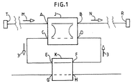
図1および図2に示す各システムは、それぞれ複数のチャネルを含むマルチプレックスを伝送する。これらのチャネルは、伝送すべき情報を搬送する光波からなる。光波は、波長のそれぞれの所定の帯域内にあり、すべての帯域は、以後伝送スペクトラムと呼ぶ所定のスペクトラムの内側にある。各チャネルは、通常、専用の単一波長を有する搬送波を含む。ただし、この搬送波は、伝送すべき信号や時間分割多重化できる複数のそのような信号によって変調され、その結果、搬送波のスペクトラムの幅は広がり、チャネルの全スペクトラムを占有することができる。マルチプレックスとチャネルは、少なくとも長距離伝送に関して、この目的のために光ファイバを組み込むこれらのシステム内で導かれる。
【0019】
2つのシステムはそれぞれ次の構成要素を含む。
【0020】
伝送すべき情報を受信して、そこから光ファイバを介してアド・ドロップ・システムJ、Kに伝送するマルチプレックスを生成する伝送手段T。このシステムが受信するマルチプレックスは、上流のマルチプレックスMを構成する。伝送手段は、マルチプレックスのそれぞれのチャネルが、最大で、所定の最大入力パワーに等しい入力パワーを有する。最大入力パワーは、通常すべてのチャネルで同じである。
【0021】
上流のマルチプレックスを受信し、下流のマルチプレックスNを構成する別のマルチプレックスを供給するアド・ドロップ・システムJ、K。上流および下流のマルチプレックスは、通常同じ波長の帯域を使用する。ただし、スペクトラム内の位置やこれらの波長の帯域のサイズによって、2つのマルチプレックス間の差が生じ、片方の帯域の一部が空になる場合がある。
【0022】
別の光ファイバを介して下流のマルチプレックスを受信し、これに応答してそのマルチプレックスのチャネルが伝送すべき情報を供給する受信手段R。
【0023】
アド・ドロップ・システムの構成要素は、選択モジュールJと並列のユニットKとを含む。
【0024】
選択モジュールJは「選択されたスペクトラムセグメント」を定義する。このセグメントは、伝送スペクトラムの一部を構成する。このセグメントは、波長の1つまたは複数の帯域を含む場合がある。これらの帯域は、隣接していてもよいし、同じセグメント内になくてもよい他の帯域によって互いに分離されていてもよい。
【0025】
このモジュールは、上流のマルチプレックスを受信する主入力Aと下流のマルチプレックスを供給する主出力Bをそれぞれ構成する2つのポートを有する。さらに、このモジュールは、分岐ポートCと挿入ポートDをそれぞれ構成する2つのポートを有する。このモジュールは、選択されたスペクトラムセグメント内にない上流のマルチプレックスのすべてのチャネルを含むグループを選択し、中継グループを構成するこのグループを主入力Aから主出力Bまで中継用導波路に沿って導くように構成されている。またこのモジュールは、選択されたスペクトラムセグメント内の上流のマルチプレックスのすべてのチャネルのグループを選択し、分岐グループを構成するこのグループを主入力Aから分岐ポートCまで延びる分岐用導波路に沿って導くように構成されている。さらにこのモジュールは、挿入グループを構成する光波が、選択されたスペクトラムセグメント内にある場合に、前記光波を挿入ポートDから主出力Bまで延びている挿入用導波路に沿って導くように構成されている。挿入グループは、少なくとも1つのチャネルを含む。下流のマルチプレックスは、中継グループと挿入グループとを含む。また選択モジュールは、挿入グループを構成する光波が、選択されたスペクトラムセグメント内にない場合に、前記光波を挿入ポートから分岐ポートまで延びている逆方向の導波路に沿って導くように構成されている。導波路が、損失に影響されるまたは増幅器を含む、好ましくない状況に対応するために、以後、逆方向の導波損失係数を構成する損失係数で、導波路が、光波のパワーを割るものとする。この係数は通常1であるが、1より大きくてもよく、モジュール内に増幅器があれば1より小さくてもよい。
【0026】
図1、図2および図3で、上記の導波路は、モジュール内の線によってシンボル化され、線は、導波路が使用されているか否かによって実線または破線になっている。図では線は互いに完全に別々であるが、通常の選択モジュールは、光波に、各区間が複数のチャネルに共通である導波路だけを提供することを理解する必要がある。そのような導波路の区間について図3および図4に示すモジュールを参照しながら以下に説明する。
【0027】
並列のユニットKは、分岐ポートEと挿入ポートFとを構成する少なくとも2つのポートを有する。分岐ポートEは、分岐グループを受信するために、選択モジュールの分岐ポートCに接続される。再挿入期間の間、ユニットKは、分岐グループを分岐ポートEから挿入ポートFに送信する。ユニットKの挿入ポートは、選択モジュールの挿入ポートに接続され、したがって、このユニットは、分岐ポートCから選択モジュールの挿入ポートDまで該ユニットを介して延びている開放された並列の回路C−E−F−Dの一部を形成する。
【0028】
この回路によって、伝送された分岐グループは、前記挿入グループを構成できる。この分岐/挿入グループを以後再挿入グループと呼ぶ。
【0029】
並列のユニットは、通常、それぞれ並列の入力Gと並列の出力Hとを構成する2つのポートをさらに有するスイッチユニットKである。再挿入期間の間、並列のユニットは、分岐グループを、分岐ポートEから挿入ポートFに伝送する、図1および図2に示す直接的な伝送状態にある。これらの期間外では、並列のユニットは図3に示す交差された伝送状態にある。この状態では、前記ユニットは、分岐グループを、分岐ポートEから並列の出力Hに送信し、かつ/または並列の入力Gで、選択されたスペクトラムセグメント内の少なくとも1つのチャネルからなる挿入すべきグループを受信する。次いで前記ユニットは、挿入すべきグループを、その並列の入力から挿入ポートFに送信し、挿入すべきグループは、前記挿入グループを構成し、すなわち、このグループは選択モジュールJによって下流のマルチプレックスに挿入される。
【0030】
ただし、並列のユニットは、本発明の範囲を逸脱することなしにその他の機能を有することもできる。例えば、並列のユニットは、再挿入グループが搬送する信号の周波数または波形特性をモニタすることができる。
【0031】
並列の回路C−E−F−Dは、損失のある要素と増幅する要素とを含む。
【0032】
損失のある要素は、再挿入グループのパワーを1より大きい並列の損失係数で割っている。本発明の好ましい実施形態では、損失のある要素は並列のユニットKの一部である。
【0033】
増幅する要素は、並列の増幅器を構成する少なくとも1つの光増幅器を含み、増幅器システムを構成する。
【0034】
図2および図6に示す本発明の好ましい実施形態では、このユニット外に単一の並列の増幅器がある。図示されていない異なる実施形態では、並列の増幅器が、ユニットKなどのスイッチングする並列のユニット内のスイッチを構成することができ、図1の従来技術のシステムのようにユニットKの外部に、別の光増幅器を伴うことができる。
【0035】
さらに、伝送システムは、複数の光ファイバを介して上流のマルチプレックスMなどの複数のマルチプレックスを受信し、複数のその他の光ファイバを介して下流のマルチプレックスNなどの複数のマルチプレックスを供給するように、それぞれ構成されたシステムJ、Kなどの本発明による複数のアド・ドロップ・システムを含むことができる。この場合、各システムは有利には光ポンピングタイプの増幅器1などの少なくとも1つの並列の増幅器を含む。この場合、すべてのシステムは対応する1組の並列の増幅器に共通の単一のポンピング用ユニットを含むことが好ましい。
【0036】
増幅器1などの各並列の増幅器は、利得曲線を有し、光波を受信して、前記増幅器が受信した増幅すべき光波のパワーの合計である増幅器の入力のパワー値ごとに、前記曲線が定義する利得を掛けた光波のパワーの各々で、それらの光波を送信するように構成されている。したがって、並列の増幅器が受信する各チャネルは、最大でその増幅器に関係する現在の最大パワーに等しく、回路内の前記増幅器に前置される並列の回路の構成要素の損失および利得によってチャネルの前記最大入力パワーに基づいて定義されたパワーを有する。本発明のシステムの稼動時には、入力パワーは一定のまたは変動する現在値を有する。したがって、並列の増幅器の利得は、その値が常に入力パワーの現在の値の利得曲線によって定義される現在の利得である。
【0037】
並列の回路が単一の増幅器を含み、損失のある構成要素が増幅器の下流の回路内にある簡単な状況では、チャネルの現在のパワーはその入力パワーと同じである。第2の増幅器が損失のある構成要素と第1の増幅器に前置される、より複雑な状況では、チャネルごとに第2の増幅器に関係する最大の現在のパワーは、最大入力パワーを損失がある構成要素の損失係数で割り、その値に第1の増幅器の現在の利得を掛けた値に等しい。この結果、すべての増幅器のそれぞれの利得曲線は、すべての増幅器のそれぞれの入力パワーの値のそれぞれの組の並列の利得を定義し、この並列の利得は、これらの曲線がそれらの値についてそれぞれ定義したすべての利得の積である。したがって、並列の利得は、入力パワーが増大するにつれて減少する。現在の並列の利得が、入力パワーのすべての現在の値について利得曲線が定義する利得の場合、システムの入力と主出力との間で、再挿入グループのパワーが並列の損失係数によって割られ、現在の並列の利得を掛けられる一方で、中継グループのパワーは変化しないことは明らかである。
【0038】
本発明のシステムは、増幅器1などの並列の増幅器の利得曲線が、逆方向の導波損失係数と並列の損失係数の積からなるループ損失係数よりも大きい並列の利得を定義し、この利得が最大の初期の組を構成する値の入力パワーの組について定義されることを特徴とする。並列の増幅器のそれぞれの入力パワー値は、この最大の初期の組では、増幅器が受信するチャネルの現在の最大パワーの合計に等しく、現在の最大パワーは、その増幅器に関係する最大パワーである。
【0039】
本発明が定義する利得曲線特性は、1つまたは複数の並列の増幅器および/または増幅器の電気または光ポンピングのパワーの選択によって得られる。この選択には正確な調整が不要である。これは並列の利得の値は、しきい値より大きければ十分で、この値は、再挿入グループの現在の最大パワーに等しい入力パワーの利得曲線が定義する値であることを理由とする。このしきい値は、前もって知られているか実験的に決定でき、あるいは利得曲線の少なくとも1つのレベルが、ループ波が増加する点まで漸進的に増大する場合には具体的に指定しなくてもよい(以下参照)。実際、時間に応じた並列の増幅器の利得の低下によって並列の利得がしきい値を下回る危険がない安全マージンを作成できる程度に十分にこのレベルを上げることが有利である。そのような利得の低下は、増幅器自体またはその利得曲線のレベルを低下させるポンピング用ユニットの特性の劣化、あるいはマルチプレックスのパワーの予期しない増加によって引き起こされる。
【0040】
本発明のこの特徴の影響について説明するために、各並列の増幅器の入力パワーが増幅器によって受信されたチャネルのパワーの合計にすぎない初期状況を考える必要がある。この状況では、この特徴は、その最大値の限界内のチャネルの入力パワーの変化にかかわらず、並列の損失係数に対する過剰な並列の利得を生み出す。この過剰利得は2つの結果を生む。第1の結果は、再挿入グループが過剰利得によって相対的な形で増幅され、その結果、下流のマルチプレックスのグループに関するパワーのアンバランスが発生する。過剰利得の第2の結果は、アド・ドロップ・システムによって一部の光波が、閉ループC−E−F−D−C内を移動するということに関係する。該当する光波は、選択されたスペクトラムセグメント外の光波である。ループは、選択モジュールの分岐ポートを通過し、次いでモジュールの挿入ポートDまで並列の回路C−E−F−Dをたどり、モジュールを通過してその分岐ポートCに至る。初期状況では、過剰利得は閉ループ内にある。したがって、過剰利得は、レーザ効果によってループ内に光波を生成する。この光波は、選択されたスペクトラムセグメント外にあり、ループ波を構成する。次いで、そのパワーが、分岐及び再挿入グループのチャネルのパワーに加算され、並列の増幅器の入力パワーを構成する。したがって、上記の初期状況は望ましくもなくまた安定してもいない。この状況は、一時的な形でだけ達成できる。この状況が達成されるとすぐに、ループ波のパワーが増大する。したがって、並列の増幅器の入力パワーが増大し、これによって並列の利得と過剰利得が漸進的に減少する。ループ波を発生させる過剰利得が消滅する、すなわち、並列の利得がループの損失係数に等しくなると、ループ波の増加は止まる。この場合、この係数が時間と共に多少変化しても、ループ波は並列の利得をこの係数と同じ値に維持する。ループ波がたどるループは「利得調整ループ」とも呼ばれる。
【0041】
好ましい実施形態では、中継グループは増幅の損失を受けず、再挿入グループが受ける損失はループ波が受ける損失と同じである。したがって、上流のマルチプレックスがやはりバランスが取られていた状況では、本発明は下流のマルチプレックスの永続的な自動のバランスを簡単な形で達成する。実際、これは再挿入グループが受ける損失が並列のユニット内に局所化する程度まで達成される。その他の場合には、分岐グループが選択モジュールの損失を受け、下流のマルチプレックスのバランスは、より不正確であるがそれでも有利である。
【0042】
中継グループとループ波の不要な結合が選択モジュール内で発生することがある。このために、アド・ドロップ・システムは、利得調整ループ内にスペクトラムロッキングユニット2をさらに含む。このユニットは、ループ波にやはりスペクトラム外の波長を加えるために、前記伝送スペクトラム外の波長を優先し、ループ波長を構成する。好ましい実施形態では、このユニットは、並列の回路C−E−F−Dに直列に接続された帯域通過フィルタである。この帯域通過フィルタは、再挿入グループ内の過剰損失を招かない程度に十分弱い選択度を有するが、その選択度は、適した所定のループ波長を加えるのに十分である。
【0043】
この解決策には簡単であるという利点がある。当然ながら当業者は他の多くの解決策を考えることができる。したがって、他の実施形態では、このユニットは、並列の回路内の増幅器と並列に、または選択モジュール内で直接に接続することができる。
【0044】
選択モジュールのさまざまな実施形態について以下に説明する。図4に示す実施形態では、選択モジュールは、2つの分岐の各々が除波フィルタ4を構成する光学的に書き込まれたブラッグ格子を含む光ファイバ・マッハツェンダー干渉計の形をしている。この干渉計は、1つの分岐のセグメント12内で紫外線放射による処理でバランスが取られ、その内部の光波伝搬速度を調整する。この種のフィルタを使用するすべての実施形態で、選択されたスペクトラムセグメントは、フィルタが除波したスペクトラムセグメントである。この実施形態では、中継チャネルは2つの区間A−4および4−Bを有し、分岐チャネルは2つの区間A−4および4−Cを有し、挿入チャネルは2つの区間D−4および4−Bを有し、逆方向の導波路は2つの区間D−4および4−Cを有し、これらの区間はそれぞれ干渉計の2つの分岐間のその長さの一部にわたって分割される。
【0045】
図5で、選択モジュールは、帯域通過フィルタを構成するファブリペロー(Fabry−Perot)共振器7のそれぞれの反対の側に2つの光サーキュレータ5および6を含む。選択されたスペクトラムセグメントは、フィルタが送信するセグメントである。中継チャネルは区間A−5、5−7、7−5および5−Bを有する。分岐チャネルは区間A−5、5−7、7−6および6−Cを有する。挿入チャネルは区間D−6、6−7、7−5および5−Bを有する。逆方向の導波路は区間D−6、6−7、7−6および6−Cを有する。利得調整ループは導波路C−E−F−D−6−7−6−Cをたどり、ポートEおよびFはポートCとDとの間に接続された並列のユニットKのポートで、図示されていない。波の伝搬方向は図示されていない並列の増幅器または光アイソレータによって強制的に決定される。
【0046】
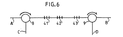
図6に選択モジュールの現在の好ましい実施形態を示す。このモジュールを含むアド・ドロップ・システムにおいて測定が実行されている。このモジュールは、2つの光サーキュレータ8と9との間に直列に接続され、上流のマルチプレックス内の3つのチャネルR1、R2およびR4の中央波長にそれぞれ同調される、3つの除波フィルタ41、42および43を含んでいた。これら3つのチャネルは、再挿入グループを構成していた。マルチプレックス内の別のチャネルR3は、中継グループを構成していた。表のWLのカラムは、4つのチャネルとそのナノメートル単位の中央波長を示す。カラムPA、PB1およびPB2は、主入力Aと、増幅器なしの主出力Bと、本発明に従ってErドープファイバ型の並列の増幅器を含む同じ出力とで、それぞれ測定された対応するチャネルのパワーをdB単位で示す。
【0047】
【表1】

【図面の簡単な説明】
【図1】再挿入期間に適用される従来技術の伝送システムの一構成を示す図である。
【図2】再挿入期間に適用される本発明のアド・ドロップ・システムを含む伝送システムの一構成を示す図である。
【図3】再挿入期間外に適用される図2のシステムの一構成を示す図である。
【図4】図2および図3のシステムの選択モジュールの第1の実施形態を示す図である。
【図5】図2および図3のシステムの選択モジュールの第2の実施形態を示す図である。
【図6】図2および図3のシステムの選択モジュールの第3の実施形態を示す図である。
【符号の説明】
1 増幅器
2 スペクトラムロッキングユニット
4 除波フィルタ
5、6、8、9 光サーキュレータ
7 ファブリペロー共振器
12 分岐のセグメント
41、42、43 除波フィルタ
A、B 主入力
C、E 分岐ポート
D、F 挿入ポート
G 並列の入力
H 並列の出力
J 選択モジュール
K 並列のユニット
M 上流のマルチプレックス
N 下流のマルチプレックス
R 受信手段
T 伝送手段[0001]
BACKGROUND OF THE INVENTION
The present invention relates to the field of transmission using optical wavelength division multiplexing. In particular, the present invention relates to a method for selectively inserting and / or dropping one or more multiplexed channels.
[0002]
Such an operation is useful for routing and switching functions. For example, such an operation can be used to change information about one or more channels or to change the wavelength of a channel carrying information. An add / drop system that performs these operations is commonly referred to as an optical add / drop multiplexer (OADM).
[0003]
[Prior art]
The method of the present invention includes the following operations disclosed in the patent document EP-A-0838918 published on April 29, 1998, but the terms used in the following description of these operations are used in the above documents. The term is different.
[0004]
Information to be transmitted is carried by a plurality of channels, a part of the channels aggregate to form an upstream multiplex, the channels of the multiplex being distributed in the wavelength spectrum, and the upstream multiplex's The channels are separated into at least one dropped group and at least one transit group in the selection module;
The branch group is shunted into parallel circuits,
At least during the reinsertion period, at least part of the branch group is shunted to the optical amplifier, which constitutes a parallel amplifier,
A relay group aggregates with a part of the branch group to form a downstream multiplex.
[0005]
The reinsertion period appears when the branch group has not changed.
[0006]
[Problems to be solved by the invention]
In fact, the parallel circuit causes unnecessary power loss in the branch group. In any transmission system, it is desirable to balance each multiplex, that is, to make all channels of the multiplex approximately the same power. Therefore, in the normal case where the upstream multiplex is balanced, the general problem of balancing the downstream multiplex arises, and the more specific problem is the loss in parallel circuits Nevertheless, achieving this balance during the reinsertion period.
[0007]
The following solutions can be considered for this more specific problem.
[0008]
In the first solution, the selection module supplies the relay channel group with a circuit that is not used by the branch channel group. In that case, the circuit includes an attenuator (possibly with the help of a parallel amplifier) that compensates for losses in the parallel circuit. This first solution has two drawbacks. One disadvantage is that the power of the channel is lower in the downstream multiplex than in the upstream multiplex, and an amplifier must be provided at the output of the selection module, while the other is It is more complex and expensive than a regular module.
[0009]
In the second solution, the gain of the parallel amplifier is changed to compensate for the loss in the parallel circuit. This second solution is not described in patent document EP-A-0 389 918, which shows only the switching function for this amplifier, and the scaling factor defining the gain of the amplifier implementing this function includes the amplifier. In general, the value is 0 when the optical circuit is opened, and 1 when the light wave is transmitted without changing its power. This solution makes it difficult to initially set the gain of the amplifier, so that this gain can be changed by upstream multiplex power fluctuations and / or deviations in the specification of the amplifier itself or by the unit feeding the amplifier. Therefore, there is a drawback that loss compensation may be hindered.
[0010]
A third solution is F.I. Shehadeh, R.A. S. Vodhanel, M.M. Krain, C.I. Gibbons, R.D. E. Wagner and M.W. Ali's paper “Gain-Wavelength WDM Optical Add-drop Multiplexer with an 8-dB Dynamic Range”, IEEE Photonics Technology Letters, vol. 7, no. 9, Sep. 1995, pp. 1075-1077. The multiplexed channels at the output of the add and drop system are separated from each other in the demultiplexer, after which the power of each channel is adjusted to a common value, and then the channels are superimposed and balanced. Configure a downstream multiplex. This solution has the disadvantage of being expensive.
[0011]
The object of the present invention is, among other things, to balance the multiplex received by the add-drop system, where the system takes a part of the channel from the received multiplex and then re-transmits the same channel into the output multiplex. Finding a way to balance the output multiplex of the add-drop system at insertion time, at a permanent and low cost. A more general object of the present invention is to prevent a system of the above type from changing the power ratio of each of the multiplexed channels when some channels are thus branched and then inserted. That is.
[0012]
[Means for Solving the Problems]
Two facts are exploited to achieve the above objective. One of these facts is that prior art optical amplifiers that can be used in parallel amplifiers are progressively saturated amplifiers, i.e., gains that decrease with the overall power of the light waves that the amplifier receives to amplify within the amplifiers. It is to have. The other fact is that within the low cost modules that make up the selection module of the prior art add / drop system, the lightwave can be directed to a different channel than the channel used in the prior art system.
[0013]
The present invention comprises a method for branching and inserting a channel used in optical wavelength division multiplexing transmission, and the method includes the following operations.
[0014]
Information to be transmitted is carried by multiple channels, and a part of the channels aggregate to form an upstream multiplex, the multiplex channels are distributed in the wavelength spectrum, and the upstream multiplex channel is selected Separated into at least one branch group and at least one relay group in the module;
The branch group is shunted into parallel circuits,
At least during a reinsertion period, at least a portion of the branch group is shunted to an amplifier system having a gradual saturation gain;
A relay group aggregates with a part of the branch group to form a downstream multiplex.
[0015]
In the method, the gain of the amplifier system is sufficiently increased to generate a light wave in the parallel circuit and the amplifier system simultaneously with a part of the branch group, and the selection module further increases the light wave constituting the loop wave with the module. It is configured to allow light waves to circulate within the closed loop it contains, and the preferred wavelength of the loop wave is outside the spectrum occupied by the channel.
[0016]
The invention also comprises an add-drop system configured to receive an upstream multiplex composed of channels wavelength-divided within a transmission spectrum, the system comprising:
The upstream multiplex channel is separated into at least one branch group and at least one relay group, and the relay group is assembled with the insertion group received by the module to form a downstream multiplex, within the wavelength spectrum A selection module consisting of at least one channel in a different location from the relay group;
A parallel unit configured to transmit at least a portion of a branch group to a selection module and to form a parallel circuit that constitutes the insertion group such that the insertion group constitutes a reinsertion group, And a parallel unit comprising an amplifier system having a gradual saturation gain,
In the system, the gain of the amplifier system has a value sufficient to generate a light wave in the parallel circuit and the amplifier system simultaneously with the reinsertion group, and the light wave circulates in a closed loop including the module by the selection module. The light wave constitutes a loop wave, the loop constitutes a gain adjustment loop, and the system further includes a spectrum locking element within the gain adjustment loop, again to add a wavelength outside the spectrum to the loop wave. Prioritize outside wavelengths.
[0017]
Various embodiments of the present invention are described below with the help of the accompanying drawings. Where components are shown in multiple figures, they are always designated with the same reference characters and / or numbers in the figures.
[0018]
DETAILED DESCRIPTION OF THE INVENTION
Each system shown in FIGS. 1 and 2 transmits a multiplex including a plurality of channels. These channels consist of light waves that carry information to be transmitted. The lightwaves are within respective predetermined bands of wavelengths, and all bands are inside a predetermined spectrum, hereinafter referred to as the transmission spectrum. Each channel typically includes a carrier having a dedicated single wavelength. However, this carrier wave is modulated by the signal to be transmitted and a plurality of such signals that can be time-division multiplexed, so that the spectrum width of the carrier wave is widened and can occupy the entire spectrum of the channel. Multiplexes and channels are routed in these systems that incorporate optical fiber for this purpose, at least for long-distance transmission.
[0019]
Each of the two systems includes the following components:
[0020]
A transmission means T that receives information to be transmitted and generates a multiplex from which information is transmitted to an add / drop system J, K via an optical fiber. The multiplex received by this system constitutes the upstream multiplex M. In the transmission means, each channel of the multiplex has an input power which is at most equal to a predetermined maximum input power. The maximum input power is usually the same for all channels.
[0021]
An add-drop system J, K that receives the upstream multiplex and supplies another multiplex comprising the downstream multiplex N. Upstream and downstream multiplexes usually use the same wavelength band. However, depending on the position in the spectrum and the size of the band of these wavelengths, a difference between the two multiplexes may occur, and a part of one band may become empty.
[0022]
Receiving means R for receiving a downstream multiplex via another optical fiber and in response supplying information to be transmitted by the channels of the multiplex.
[0023]
The components of the add / drop system include a selection module J and a parallel unit K.
[0024]
Selection module J defines a “selected spectrum segment”. This segment constitutes part of the transmission spectrum. This segment may include one or more bands of wavelengths. These bands may be adjacent or separated from each other by other bands that may not be in the same segment.
[0025]
This module has two ports, each comprising a main input A that receives the upstream multiplex and a main output B that supplies the downstream multiplex. Further, this module has two ports that constitute a branch port C and an insertion port D, respectively. This module selects a group that includes all the channels of the upstream multiplex that are not within the selected spectrum segment, and this group comprising the relay group is routed from the main input A to the main output B along the relay waveguide. It is configured to guide. The module also selects a group of all channels of the upstream multiplex in the selected spectrum segment and follows this branching waveguide extending from the main input A to the branching port C along the branching waveguide. It is configured to guide. Further, the module is configured to guide the light wave along an insertion waveguide extending from the insertion port D to the main output B when the light waves constituting the insertion group are within a selected spectrum segment. ing. The insertion group includes at least one channel. The downstream multiplex includes a relay group and an insertion group. The selection module is configured to guide the light wave along a reverse waveguide extending from the insertion port to the branch port when the light wave constituting the insertion group is not within the selected spectrum segment. Yes. In order to cope with the unfavorable situation where the waveguide is affected by loss or includes an amplifier, the waveguide will then divide the power of the lightwave with a loss factor that constitutes the reverse waveguide loss factor. To do. This coefficient is usually 1, but may be larger than 1, and may be smaller than 1 if there is an amplifier in the module.
[0026]
In FIG. 1, FIG. 2, and FIG. 3, the above waveguide is symbolized by a line in the module, and the line is a solid line or a broken line depending on whether the waveguide is used or not. Although the lines are completely separate from each other in the figure, it should be understood that a typical selection module only provides light waves with waveguides where each section is common to multiple channels. Such a section of the waveguide will be described below with reference to the modules shown in FIGS.
[0027]
The parallel unit K has at least two ports constituting a branch port E and an insertion port F. Branch port E is connected to branch port C of the selection module to receive the branch group. During the reinsertion period, unit K transmits the branch group from branch port E to insert port F. The insertion port of unit K is connected to the insertion port of the selection module, so that this unit is an open parallel circuit CE extending through the unit from branch port C to insertion port D of the selection module. -F-D forms part.
[0028]
With this circuit, the transmitted branch group can constitute the insertion group. This branch / insert group is hereinafter referred to as a reinsert group.
[0029]
The parallel unit is typically a switch unit K that further includes two ports that each constitute a parallel input G and a parallel output H. During the reinsertion period, the parallel units are in the direct transmission state shown in FIGS. 1 and 2, transmitting the branch group from the branch port E to the insertion port F. Outside these periods, the parallel units are in the crossed transmission state shown in FIG. In this state, the unit transmits a branch group from the branch port E to the parallel output H and / or with a parallel input G, a group to be inserted consisting of at least one channel in the selected spectrum segment Receive. The unit then sends the group to be inserted from its parallel input to the insertion port F, and the group to be inserted constitutes the insertion group, i.e. this group is sent to the downstream multiplex by the selection module J. Inserted.
[0030]
However, the parallel units may have other functions without departing from the scope of the present invention. For example, parallel units can monitor the frequency or waveform characteristics of the signals carried by the reinsertion group.
[0031]
The parallel circuit C-E-F-D includes a lossy element and an amplifying element.
[0032]
The lossy element divides the power of the reinsertion group by a parallel loss factor greater than one. In a preferred embodiment of the invention, the lossy element is part of the parallel unit K.
[0033]
The amplifying element includes at least one optical amplifier constituting a parallel amplifier and constitutes an amplifier system.
[0034]
In the preferred embodiment of the invention shown in FIGS. 2 and 6, there is a single parallel amplifier outside this unit. In a different embodiment, not shown, the parallel amplifiers can constitute a switch in a switching parallel unit, such as unit K, outside of unit K as in the prior art system of FIG. Of optical amplifiers.
[0035]
In addition, the transmission system receives multiple multiplexes such as upstream multiplex M via multiple optical fibers and supplies multiple multiplexes such as downstream multiplex N via multiple other optical fibers. As such, multiple add / drop systems according to the present invention can be included, such as each configured system J, K. In this case, each system advantageously includes at least one parallel amplifier, such as an optical pumping type amplifier 1. In this case, all systems preferably include a single pumping unit common to a corresponding set of parallel amplifiers.
[0036]
Each parallel amplifier, such as amplifier 1, has a gain curve, which defines the curve for each input power value of the amplifier that receives the light wave and is the sum of the power of the light waves to be amplified received by the amplifier. Each of the powers of the light waves multiplied by the gain is configured to transmit the light waves. Thus, each channel received by a parallel amplifier is at most equal to the current maximum power associated with that amplifier, and the channel's loss and gain are preceded by the loss and gain of the parallel circuit components preceding the amplifier in the circuit. Has a defined power based on the maximum input power. When the system of the present invention is in operation, the input power has a constant or variable current value. Thus, the gain of the parallel amplifier is the current gain whose value is always defined by the gain curve of the current value of the input power.
[0037]
In the simple situation where the parallel circuit includes a single amplifier and the lossy component is in the circuit downstream of the amplifier, the current power of the channel is the same as its input power. In more complex situations where the second amplifier is preceded by a lossy component and the first amplifier, the maximum current power associated with the second amplifier per channel will cause the maximum input power to be lost. Divide by the loss factor of a component and equal its value multiplied by the current gain of the first amplifier. As a result, the respective gain curves of all amplifiers define the parallel gain of each set of the respective input power values of all amplifiers, and this parallel gain is determined by the curves for each of those values. The product of all defined gains. Thus, the parallel gain decreases as the input power increases. If the current parallel gain is the gain defined by the gain curve for all current values of input power, the power of the reinsertion group is divided by the parallel loss factor between the system input and the main output, Obviously, while being multiplied by the current parallel gain, the power of the relay group does not change.
[0038]
The system of the present invention defines a parallel gain in which the gain curve of a parallel amplifier, such as amplifier 1, is greater than the loop loss factor, which is the product of the reverse waveguide loss factor and the parallel loss factor. It is characterized in that it is defined for the set of input powers of the values that make up the largest initial set. The input power value of each of the parallel amplifiers is equal to the sum of the current maximum power of the channels that the amplifier receives in this maximum initial set, where the current maximum power is the maximum power associated with that amplifier.
[0039]
The gain curve characteristics defined by the present invention are obtained by selection of one or more parallel amplifiers and / or electrical or optical pumping power of the amplifiers. This selection does not require precise adjustment. This is because the value of the parallel gain is sufficient if it is greater than the threshold, which is the value defined by the input power gain curve equal to the current maximum power of the reinsertion group. This threshold is known in advance or can be determined empirically, or may not be specifically specified if at least one level of the gain curve increases progressively to the point where the loop wave increases. Good (see below). In fact, it is advantageous to raise this level enough to create a safety margin that does not risk the parallel gain below the threshold due to the reduction in gain of the parallel amplifier as a function of time. Such a decrease in gain is caused by a degradation in the characteristics of the pumping unit that reduces the level of the amplifier itself or its gain curve, or an unexpected increase in the power of the multiplex.
[0040]
To illustrate the effect of this feature of the present invention, it is necessary to consider an initial situation where the input power of each parallel amplifier is only the sum of the power of the channels received by the amplifier. In this situation, this feature creates excessive parallel gain over the parallel loss factor, regardless of changes in the input power of the channel within its maximum limits. This excess gain has two consequences. The first result is that the reinsertion group is amplified relative to the excess gain, resulting in a power imbalance for the downstream multiplex group. The second result of excess gain is related to the fact that some light waves travel in the closed loop C-E-F-D-C due to the add-drop system. The corresponding light wave is a light wave outside the selected spectrum segment. The loop passes through the branch port of the selected module, then follows a parallel circuit C-EFD to the module insertion port D, and passes through the module to its branch port C. In the initial situation, the excess gain is in a closed loop. Thus, the excess gain generates a light wave in the loop due to the laser effect. This light wave is outside the selected spectrum segment and constitutes a loop wave. That power is then added to the power of the branch and reinsertion group channels to constitute the input power of the parallel amplifiers. Thus, the initial situation described above is neither desirable nor stable. This situation can only be achieved on a temporary basis. As soon as this situation is achieved, the power of the loop wave increases. Thus, the input power of the parallel amplifier is increased, which progressively decreases the parallel gain and excess gain. When the excess gain generating the loop wave disappears, that is, when the parallel gain becomes equal to the loss factor of the loop, the increase of the loop wave stops. In this case, the loop wave maintains the parallel gain at the same value as this coefficient, even if this coefficient changes somewhat with time. The loop that the loop wave follows is also called a “gain adjustment loop”.
[0041]
In the preferred embodiment, the relay group is not subject to amplification loss and the loss experienced by the reinsertion group is the same as the loss experienced by the loop wave. Thus, in situations where the upstream multiplex was still balanced, the present invention achieves a permanent automatic balance of the downstream multiplex in a simple manner. In fact, this is achieved to the extent that the loss experienced by the reinsertion group is localized in parallel units. In other cases, the branch group suffers the loss of the selection module, and the downstream multiplex balance is still less advantageous but advantageous.
[0042]
Unnecessary coupling of relay groups and loop waves may occur in the selection module. For this purpose, the add / drop system further includes a spectrum locking unit 2 in the gain adjustment loop. In order to add a wavelength outside the spectrum to the loop wave, this unit gives priority to the wavelength outside the transmission spectrum and configures the loop wavelength. In a preferred embodiment, this unit is a bandpass filter connected in series with a parallel circuit CEFD. This bandpass filter has a selectivity that is sufficiently weak that it does not cause excess loss in the reinsertion group, but that selectivity is sufficient to add a suitable predetermined loop wavelength.
[0043]
This solution has the advantage of being simple. Of course, those skilled in the art can envision many other solutions. Thus, in other embodiments, this unit can be connected in parallel with an amplifier in a parallel circuit or directly in a selection module.
[0044]
Various embodiments of the selection module are described below. In the embodiment shown in FIG. 4, the selection module is in the form of a fiber optic Mach-Zehnder interferometer that includes an optically written Bragg grating in which each of the two branches constitutes a rejection filter 4. This interferometer is balanced by treatment with ultraviolet radiation within one branch segment 12 and adjusts the speed of light wave propagation within it. In all embodiments that use this type of filter, the selected spectrum segment is the spectrum segment that the filter has rejected. In this embodiment, the relay channel has two sections A-4 and 4-B, the branch channel has two sections A-4 and 4-C, and the insertion channel has two sections D-4 and 4C. -B, the reverse waveguide has two sections D-4 and 4-C, each of which is divided over a portion of its length between the two branches of the interferometer.
[0045]
In FIG. 5, the selection module includes two optical circulators 5 and 6 on each opposite side of a Fabry-Perot resonator 7 constituting a bandpass filter. The selected spectrum segment is the segment that the filter transmits. The relay channel has sections A-5, 5-7, 7-5 and 5-B. The branch channel has sections A-5, 5-7, 7-6 and 6-C. The insertion channel has sections D-6, 6-7, 7-5 and 5-B. The reverse waveguide has sections D-6, 6-7, 7-6 and 6-C. The gain adjustment loop follows waveguide C-E-F-D-6-7-6-C, and ports E and F are the ports of parallel unit K connected between ports C and D, as shown. Not. The wave propagation direction is forcibly determined by a parallel amplifier or optical isolator (not shown).
[0046]
FIG. 6 shows a presently preferred embodiment of the selection module. Measurements are being performed in an add-drop system that includes this module. This module is connected in series between two optical circulators 8 and 9 and is tuned to the center wavelength of three channels R1, R2 and R4 in the upstream multiplex, respectively, 42 and 43 were included. These three channels constituted a reinsertion group. Another channel R3 in the multiplex constitutes a relay group. The WL column in the table shows the four channels and their center wavelength in nanometers. Columns PA, PB1 and PB2 respectively measure the power of the corresponding channel measured in main input A, main output B without amplifier, and the same output including an Er-doped fiber type parallel amplifier according to the present invention in dB. Shown in units.
[0047]
[Table 1]
[Brief description of the drawings]
FIG. 1 is a diagram showing a configuration of a transmission system of a prior art applied in a reinsertion period.
FIG. 2 is a diagram showing a configuration of a transmission system including an add / drop system of the present invention applied in a reinsertion period.
FIG. 3 is a diagram showing a configuration of the system of FIG. 2 applied outside the reinsertion period.
4 shows a first embodiment of a selection module of the system of FIGS. 2 and 3. FIG.
5 shows a second embodiment of a selection module of the system of FIGS. 2 and 3. FIG.
6 shows a third embodiment of the selection module of the system of FIGS. 2 and 3. FIG.
[Explanation of symbols]
1 Amplifier
2 Spectrum locking unit
4 filter
5, 6, 8, 9 Optical circulator
7 Fabry-Perot resonator
12 branch segments
41, 42, 43 filter
A, B Main input
C, E branch port
D, F insertion port
G Parallel input
H Parallel output
J selection module
K parallel units
M Upstream multiplex
N Downstream multiplex
R receiving means
T Transmission means
Claims (7)
伝送すべき情報が複数のチャネルによって搬送され、前記チャネルの一部が集合して上流のマルチプレックスを形成し、前記マルチプレックスのチャネルが波長スペクトラム中に分散され、前記上流のマルチプレックスの前記チャネルが選択モジュール内で少なくとも1つの分岐グループと少なくとも1つの中継グループに分離される操作と、
前記分岐グループが並列の回路に分流される操作と、
少なくとも、前記分岐グループの前記中継グループへの再挿入動作が行われる再挿入期間中に、前記分岐グループの少なくとも一部が漸進的な飽和利得を有する増幅器システムに分流される操作と、
前記中継グループを前記分岐グループの前記一部と集合させて下流のマルチプレックスを形成する操作とを含み、
前記増幅器システムは前記選択モジュールの分岐ポートから前記並列の回路を介して前記選択モジュールの挿入ポートまで延びる回路中に配置され、前記増幅器システムの利得が、前記並列の回路と前記増幅器システム内で、光波を発生するのに十分に高められ、前記選択モジュールが、前記モジュールをさらに含む閉ループ内で、前記光波が循環できるように構成され、前記光波がループ波を構成し、前記ループ波の波長が、前記チャネルによって占有されるスペクトラムの外側にある方法。A method of branching and inserting a channel used in optical wavelength division multiplexing transmission,
Information to be transmitted is carried by a plurality of channels, a part of the channels aggregate to form an upstream multiplex, and the channels of the multiplex are dispersed in the wavelength spectrum, the channels of the upstream multiplex Is separated into at least one branch group and at least one relay group in the selection module;
An operation in which the branch group is shunted into a parallel circuit;
An operation in which at least a part of the branch group is shunted to an amplifier system having a gradual saturation gain during a reinsertion period during which a reinsertion operation of the branch group into the relay group is performed ;
Combining the relay group with the portion of the branch group to form a downstream multiplex,
The amplifier system is disposed in a circuit extending from a branch port of the selection module through the parallel circuit to an insertion port of the selection module, and the gain of the amplifier system is within the parallel circuit and the amplifier system, The selection module is configured to allow the light wave to circulate within a closed loop further including the module, the light wave constitutes a loop wave , and the wavelength of the loop wave is increased. A method outside the spectrum occupied by the channel.
前記上流のマルチプレックスの前記チャネルを少なくとも1つの分岐グループと少なくとも1つの中継グループに分離し、前記中継グループを選択モジュールによって受信された挿入グループと集合させることで下流のマルチプレックスを形成し、前記中継グループとは異なる前記波長スペクトラム内の場所にある少なくとも1つのチャネルからなる選択モジュールと、
前記分岐グループの少なくとも一部を前記選択モジュールに伝送して、前記分岐グループの少なくとも一部により構成された挿入グループである再挿入グループを前記選択モジュールに入力するための、並列の回路を形成する並列のユニットであって、前記並列の回路が漸進的な飽和利得を有する増幅器システムを含む並列のユニットとを含み、
前記増幅器システムは前記選択モジュールの分岐ポートから前記並列の回路を介して前記選択モジュールの挿入ポートまで延びる回路中に配置され、前記増幅器システムの前記利得が、前記並列の回路と前記増幅器システム内に光波を発生させるのに十分な値を有し、前記選択モジュールにより光波が前記選択モジュールをも含む閉ループ内を循環でき、前記光波がループ波を構成し、前記ループが利得調整ループを構成し、前記アド・ドロップ・システムが、前記利得調整ループ内にスペクトラムロッキング要素をさらに含み、前記スペクトラム外の波長を前記ループ波に加えるために前記チャネルによって占有されるスペクトラム外の波長を通過させるシステム。An add / drop system configured to receive an upstream multiplex composed of channels that are wavelength-divided within the transmission spectrum,
Separating the channels of the upstream multiplex into at least one branch group and at least one relay group, and combining the relay group with an insertion group received by a selection module to form a downstream multiplex, A selection module comprising at least one channel at a location in the wavelength spectrum different from the relay group;
And transmit at least a portion of the branch groups to the selection module, forms at least a part for inputting a reinserted group which is configured inserted group to the selected module, the circuit of the parallel of the branch group a unit parallel to, and a parallel unit circuit of the parallel comprises an amplifier system having a progressive saturation gain,
The amplifier system is arranged in a circuit extending from the branch port to the insertion port of the selected module via the circuit of the parallel of the selected module, the gain of the amplifier system, before Symbol parallel circuit and in the amplifier system The selection module can circulate the light wave in a closed loop including the selection module, the light wave forms a loop wave, and the loop forms a gain adjustment loop. the add-drop system, the further saw including a spectrum locking element in the gain adjustment loop, thereby the wavelength outside before Symbol spectrum passing wavelengths outside the spectrum occupied by the channel to be added to said loop wave system.
Applications Claiming Priority (2)
| Application Number | Priority Date | Filing Date | Title |
|---|---|---|---|
| FR9812935A FR2784827B1 (en) | 1998-10-15 | 1998-10-15 | WAVELENGTH MULTIPLEX OPTICAL TRANSMISSION METHOD AND SYSTEM WITH CHANNEL EXTRACTION AND INSERTION |
| FR9812935 | 1998-10-15 |
Publications (2)
| Publication Number | Publication Date |
|---|---|
| JP2000134152A JP2000134152A (en) | 2000-05-12 |
| JP4169441B2 true JP4169441B2 (en) | 2008-10-22 |
Family
ID=9531600
Family Applications (1)
| Application Number | Title | Priority Date | Filing Date |
|---|---|---|---|
| JP28912999A Expired - Fee Related JP4169441B2 (en) | 1998-10-15 | 1999-10-12 | Channel insertion and branching method and optical wavelength division multiplexing transmission system |
Country Status (7)
| Country | Link |
|---|---|
| US (1) | US6476946B1 (en) |
| EP (1) | EP0994594B1 (en) |
| JP (1) | JP4169441B2 (en) |
| AT (1) | ATE323351T1 (en) |
| CA (1) | CA2286391A1 (en) |
| DE (1) | DE69930811T2 (en) |
| FR (1) | FR2784827B1 (en) |
Families Citing this family (2)
| Publication number | Priority date | Publication date | Assignee | Title |
|---|---|---|---|---|
| US6895186B2 (en) * | 2000-12-27 | 2005-05-17 | The Trustees Of Columbia University In The City Of New York | System for accessing a wavelength-division-multiplexed bidirectional optical fiber ring network |
| US6885821B2 (en) * | 2001-02-27 | 2005-04-26 | Avanex Corporation | Full-duplex optical add/drop communications system utilizing central light sources |
Family Cites Families (7)
| Publication number | Priority date | Publication date | Assignee | Title |
|---|---|---|---|---|
| JPH08264871A (en) * | 1995-03-20 | 1996-10-11 | Fujitsu Ltd | Multiple-wavelength batch optical amplifier device |
| GB9617396D0 (en) * | 1996-08-19 | 1996-10-02 | Stc Submarine Systems Ltd | Improvements in or relating to optical add/drop wavelength division multiplex systems |
| FR2755253B1 (en) * | 1996-10-24 | 1998-11-27 | Alsthom Cge Alcatel | WAVELENGTH MULTIPLEX CHANNEL EXTRACTION-INSERTION DEVICE |
| JP3555824B2 (en) * | 1996-11-21 | 2004-08-18 | 日本電気株式会社 | Branching device |
| JP3036458B2 (en) * | 1997-02-28 | 2000-04-24 | 日本電気株式会社 | Optical branching device and optical transmission method |
| US6069719A (en) * | 1997-07-30 | 2000-05-30 | Ciena Corporation | Dynamically reconfigurable optical add-drop multiplexers for WDM optical communication systems |
| US6631018B1 (en) * | 1997-08-27 | 2003-10-07 | Nortel Networks Limited | WDM optical network with passive pass-through at each node |
-
1998
- 1998-10-15 FR FR9812935A patent/FR2784827B1/en not_active Expired - Fee Related
-
1999
- 1999-10-07 CA CA002286391A patent/CA2286391A1/en not_active Abandoned
- 1999-10-11 DE DE69930811T patent/DE69930811T2/en not_active Expired - Lifetime
- 1999-10-11 EP EP99402488A patent/EP0994594B1/en not_active Expired - Lifetime
- 1999-10-11 AT AT99402488T patent/ATE323351T1/en not_active IP Right Cessation
- 1999-10-12 JP JP28912999A patent/JP4169441B2/en not_active Expired - Fee Related
- 1999-10-12 US US09/416,263 patent/US6476946B1/en not_active Expired - Lifetime
Also Published As
| Publication number | Publication date |
|---|---|
| EP0994594A1 (en) | 2000-04-19 |
| US6476946B1 (en) | 2002-11-05 |
| ATE323351T1 (en) | 2006-04-15 |
| FR2784827B1 (en) | 2002-12-20 |
| JP2000134152A (en) | 2000-05-12 |
| DE69930811D1 (en) | 2006-05-24 |
| CA2286391A1 (en) | 2000-04-15 |
| DE69930811T2 (en) | 2007-04-26 |
| FR2784827A1 (en) | 2000-04-21 |
| EP0994594B1 (en) | 2006-04-12 |
Similar Documents
| Publication | Publication Date | Title |
|---|---|---|
| US8554081B2 (en) | Optical add/drop multiplexer including reconfigurable filters and system including the same | |
| US8204379B2 (en) | Noise reduction in optical communications networks | |
| EP2510641B1 (en) | Channel power management in a branched optical communication system | |
| EP2180612A1 (en) | Control apparatus and method for optical transmission apparatus | |
| KR100334432B1 (en) | Bidirectional add/drop optical amplifier module using one arrayed-waveguide grating multiplexer | |
| JP3983293B2 (en) | Improvements in or related to optical add / drop wavelength division multiplexing systems | |
| JPH10229386A (en) | Optical fiber amplifier and optical communication using the same | |
| EP1746755B1 (en) | Optical network with sub-band rejection and bypass | |
| US6452718B1 (en) | WDM-channel equalizer | |
| EP1762029B1 (en) | Wavelength division multiplex (wdm) optical demultiplexer | |
| US6473540B1 (en) | Device and method for filtering optical wavelengths | |
| CA2353825A1 (en) | Optical amplifier | |
| JP4169441B2 (en) | Channel insertion and branching method and optical wavelength division multiplexing transmission system | |
| JP4246644B2 (en) | Optical receiver and optical transmission device | |
| JP2001156364A (en) | Wide band optical amplifier | |
| US6147785A (en) | Coherent crosstalk attenuation apparatus | |
| EP0967752A2 (en) | WDM transmission system | |
| CA2419852A1 (en) | Optical add drop and dispersion compensation apparatus | |
| US11522629B2 (en) | Channelized optical amplifiers and amplifier arrays | |
| CA2353815A1 (en) | Wdm ring transmission system having amplified dropped channels | |
| Krummrich et al. | Channel power transients in photonic networks caused by stimulated Raman scattering | |
| KR20060046888A (en) | Device and method for gain control in fiber raman amplifier | |
| US20150180583A1 (en) | Wavelength division multiplexing optical transmission device |
Legal Events
| Date | Code | Title | Description |
|---|---|---|---|
| A621 | Written request for application examination |
Free format text: JAPANESE INTERMEDIATE CODE: A621 Effective date: 20061006 |
|
| A131 | Notification of reasons for refusal |
Free format text: JAPANESE INTERMEDIATE CODE: A131 Effective date: 20071225 |
|
| A601 | Written request for extension of time |
Free format text: JAPANESE INTERMEDIATE CODE: A601 Effective date: 20080319 |
|
| A602 | Written permission of extension of time |
Free format text: JAPANESE INTERMEDIATE CODE: A602 Effective date: 20080325 |
|
| A521 | Request for written amendment filed |
Free format text: JAPANESE INTERMEDIATE CODE: A523 Effective date: 20080624 |
|
| TRDD | Decision of grant or rejection written | ||
| A01 | Written decision to grant a patent or to grant a registration (utility model) |
Free format text: JAPANESE INTERMEDIATE CODE: A01 Effective date: 20080722 |
|
| A01 | Written decision to grant a patent or to grant a registration (utility model) |
Free format text: JAPANESE INTERMEDIATE CODE: A01 |
|
| A61 | First payment of annual fees (during grant procedure) |
Free format text: JAPANESE INTERMEDIATE CODE: A61 Effective date: 20080805 |
|
| FPAY | Renewal fee payment (event date is renewal date of database) |
Free format text: PAYMENT UNTIL: 20110815 Year of fee payment: 3 |
|
| R150 | Certificate of patent or registration of utility model |
Free format text: JAPANESE INTERMEDIATE CODE: R150 |
|
| FPAY | Renewal fee payment (event date is renewal date of database) |
Free format text: PAYMENT UNTIL: 20110815 Year of fee payment: 3 |
|
| FPAY | Renewal fee payment (event date is renewal date of database) |
Free format text: PAYMENT UNTIL: 20120815 Year of fee payment: 4 |
|
| FPAY | Renewal fee payment (event date is renewal date of database) |
Free format text: PAYMENT UNTIL: 20120815 Year of fee payment: 4 |
|
| FPAY | Renewal fee payment (event date is renewal date of database) |
Free format text: PAYMENT UNTIL: 20130815 Year of fee payment: 5 |
|
| R250 | Receipt of annual fees |
Free format text: JAPANESE INTERMEDIATE CODE: R250 |
|
| R250 | Receipt of annual fees |
Free format text: JAPANESE INTERMEDIATE CODE: R250 |
|
| R250 | Receipt of annual fees |
Free format text: JAPANESE INTERMEDIATE CODE: R250 |
|
| R250 | Receipt of annual fees |
Free format text: JAPANESE INTERMEDIATE CODE: R250 |
|
| LAPS | Cancellation because of no payment of annual fees |