JP4168917B2 - Cooker using touch keys - Google Patents
Cooker using touch keys Download PDFInfo
- Publication number
- JP4168917B2 JP4168917B2 JP2003393610A JP2003393610A JP4168917B2 JP 4168917 B2 JP4168917 B2 JP 4168917B2 JP 2003393610 A JP2003393610 A JP 2003393610A JP 2003393610 A JP2003393610 A JP 2003393610A JP 4168917 B2 JP4168917 B2 JP 4168917B2
- Authority
- JP
- Japan
- Prior art keywords
- electrode
- touch key
- panel
- cooker
- touch
- Prior art date
- Legal status (The legal status is an assumption and is not a legal conclusion. Google has not performed a legal analysis and makes no representation as to the accuracy of the status listed.)
- Expired - Fee Related
Links
Images


Description
本発明は、各種の機器に用いるタッチキーを用いた調理器に関するものである。 The present invention relates to a cooking device using a touch key over for use in various devices.
従来、調理器に用いたタッチキーとしては、ガラスなどの電気絶縁物からなるパネル部の表裏両面にそれぞれ電極部を設け、これら表裏両面の電極部とパネル部でコンデンサを形成したものが知られている(例えば、特許文献1参照)。 Conventionally, as a touch key used in a cooker, an electrode part is provided on both front and back sides of a panel part made of an electrical insulator such as glass, and a capacitor is formed by the electrode part and the panel part on both the front and back sides. (For example, refer to Patent Document 1).
これは、発振部より発生した高周波電圧をパネル部裏面の電極部に印加するとともに、パネル部表面の電極部を指でタッチしたときに高周波電圧を各電極部、パネル部、指を通じてバイパスさせ、パネル部裏面の電極部に現れる電圧が低下することを検知部で検知して、電極部のタッチを知るものである。
しかしながら、前記従来の構成では、1個のタッチキーにそれぞれ一つの発振部と検知部が必要となり、機器の回路を複雑なものにするという課題があった。 However, the conventional configuration requires one oscillating unit and one detecting unit for each touch key, and there is a problem in that the circuit of the device is complicated.
本発明は、前記従来の課題を解決するもので、キーの数が増えても発振部と検知部の数を増加させる必要がなく、回路構成が簡単にできるタッチキーを用いた調理器を提供することを目的とする。 The present invention is the one that solves the conventional problem, even if the number of keys is not necessary to increase the number of detection portions and the oscillating unit, provide a cooker with a touch key over the circuit construction can be simplified The purpose is to do.
前記従来の課題を解決するために、本発明のタッチキーを用いた調理器は、電気絶縁物よりなるパネル部と、このパネル部の表裏両面に対向して設けた電極部と、所定の周波数の電圧を出力して前記パネル部の裏面に設けた電極部に印加する発振部と、前記電極部の出力電圧を検知する検知部とを備え、前記パネル部の前記表面に設けた電極部は複数とし、前記裏面に設けた電極部は、前記表面の複数の電極部にまたがって一つ設け前記表面の各電極部間で形成される対向面積が相互に異なるように配置したものである。 In order to solve the above-described conventional problems, a cooker using a touch key according to the present invention includes a panel portion made of an electrical insulator, electrode portions facing the front and back surfaces of the panel portion, and a predetermined frequency. an oscillator for outputting a voltage applied to the electrode portion provided on the rear surface of the panel portion, and a detector for detecting an output voltage of the electrode portions, the electrode portion provided on the surface of the panel portion and plural electrode portion provided on the back surface, in which the opposing area formed between the electrode portions of the surfaces provided one over a plurality of electrode portions of the surface is arranged so as to differ from each other .
これにより、キーの数が増えても発振部と検知部の数を増加させる必要がなくなり回路構成が簡単にできるものである。 Thereby, even if the number of keys increases, it is not necessary to increase the number of oscillation units and detection units, and the circuit configuration can be simplified.
また、本発明のタッチキーを用いた調理器とすることにより、回路構成が簡単にでき、コンパクトな調理器が得られ、安全性、使用性を高めることも可能である。 In addition, by using the cooker using the touch key of the present invention, the circuit configuration can be simplified, a compact cooker can be obtained, and safety and usability can be improved.
本発明のタッチキーとそれを用いた調理器は、キーの数が増えても発振部と検知部の数を増加させる必要がなくなり回路構成が簡単にできる。 The touch key of the present invention and the cooker using the touch key can simplify the circuit configuration because it is not necessary to increase the number of oscillation units and detection units even if the number of keys increases.
第1の発明は、電気絶縁物よりなるパネル部と、このパネル部の表裏両面に対向して設けた電極部と、所定の周波数の電圧を出力して前記パネル部の裏面に設けた電極部に印加する発振部と、前記電極部の出力電圧を検知する検知部とを備え、前記パネル部の前記表面に設けた電極部は複数とし各電極部面積を同一面積とし、前記裏面に設けた電極部は、前記表面の複数の電極部にまたがって一つ設け前記表面の各電極部間で形成される対向面積が相互に異なるように配置したとすることにより、キーの数が増えても発振部と検知部の数を増加させる必要がなくなり回路構成が簡単にできる。 A first invention is a panel unit made of an electrical insulator, an electrode unit provided opposite to both the front and back surfaces of the panel unit, and an electrode unit provided on the back surface of the panel unit that outputs a voltage of a predetermined frequency. an oscillator to be applied to, and a detector for detecting an output voltage of the electrode portions, the electrode portion provided on the surface of the panel portion is equal areas of each electrode portion area and a plurality, provided on the back surface Even if the number of keys is increased by providing one electrode portion across the plurality of electrode portions on the surface and arranging the opposing areas formed between the electrode portions on the surface to be different from each other, It is not necessary to increase the number of oscillation units and detection units, and the circuit configuration can be simplified.
また、パネル部の表面に設けた複数の電極部は、各電極部面積を同一面積とし、パネル部の裏面に設けた電極部は、前記パネル部表面の各電極部間で形成される対向面積が異なるように配置したことにより、電極部によって形成されるコンデンサの静電容量の初期値を変えることができ、同一形状の複数キーの判別が可能となる。 The counter plurality of electrode portions provided on the surface of the panel portion, each electrode portion area with the same area, the electrode portion provided on the rear surface of the panel portion is formed between the electrode portions of the panel section surface By arranging so that the areas are different, the initial value of the capacitance of the capacitor formed by the electrode portion can be changed, and a plurality of keys having the same shape can be discriminated.
また、タッチキーを用いた調理器とすることにより、回路構成が簡単にでき、コンパクトな調理器が得られ、安全性、使用性を高めることも可能である。 Further, with the cooker with data Tchiki, circuit configuration can be simple, compact cooker is obtained, the safety, it is also possible to enhance the usability.
以下、本発明の実施の形態について、図面を参照しながら説明する。なお、この実施の形態によって本発明が限定されるものではない。 Hereinafter, embodiments of the present invention will be described with reference to the drawings. Note that the present invention is not limited to the embodiments.
(実施の形態1)
図1、図2は、本発明の実施の形態1におけるタッチキーの構成を示したものである。
(Embodiment 1)
1 and 2 show the configuration of the touch key according to
図に示すように、ガラス、プラスチックなどの電気絶縁物よりなるパネル部1の表面に
電極部2、3と、裏面に電極部2、3と対向し両電極部2、3にまたがって一つの電極部4とを設けている。すなわち、パネル部1の裏面の電極部4は、パネル部1を挟んでその面積が表面の電極部2、3と重なるようになっている。電極部2、3はタッチキーのキーとなるものである。電極部2と電極部4、または電極部3と電極部4でコンデンサを構成するものである。このコンデンサは指5で電極部2または3をタッチすることにより、その静電容量が変化する。また、電極部4には、所定の周波数の電圧を出力して印加する発振部6と、前記電極部4の出力電圧を検知する検知部7が接続されている。
As shown in the figure, the
したがって、電極部2または3をタッチすることで、発振部6からの高周波電圧が指5で十分減衰され、検知部6での検知電圧はタッチした時としない時の電圧差が大きくなって電極部2または3をタッチしたと認識するものである。
Therefore, when the
このように、本実施の形態におけるタッチキーは、パネル部1の表面に複数の電極部2、3を設け、裏面に設けた電極部4は表面の複数の電極部2、3にまたがって一つ設けたことにより、キーの数が増えても発振部6と検知部7の数を増加させる必要がなくなり回路構成が簡単にできる。なお、電極部2、3は2個に限らず、それ以上あってもよいものである。
As described above, the touch key according to the present embodiment is provided with the plurality of
(実施の形態2)
図3、図4は本発明の実施の形態2におけるタッチキーを示すものである。実施の形態1と同一要素については同一符号を付して説明を省略する。
(Embodiment 2)
3 and 4 show a touch key according to Embodiment 2 of the present invention. The same elements as those of the first embodiment are denoted by the same reference numerals and the description thereof is omitted.
本実施の形態においては、電極部2または3を指5でタッチしたとき、複数キーの判別のために、電極部によって形成されるコンデンサの静電容量の初期値を変えたものである。
In the present embodiment, when the
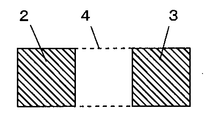
図3は、電極部2と電極部3の面積を変えたものである。静電容量は対抗する電極部の面積で決定されるため、電極部3の方を電極部2よりも電極部4と対抗する面積を小さくして、静電容量が小さくなるようにしている。なお、電極部2を電極部3の面積より小さくしても同様である。これにより、静電容量の違いでタッチキーの判別を可能にしている。
FIG. 3 shows a case where the areas of the
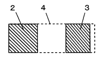
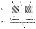
また、図4(a)(b)は、裏面の電極部4の大きさを図3の場合よりも小さくしたものであり、パネル部1表面の電極部2、3の面積が同じでも、裏面の電極部4との対向面積が異なるため、静電容量は異なり、タッチキーの判別を可能にしている。
4 (a) and 4 (b) show that the size of the
このように、本実施の形態におけるタッチキーは、電極部によって形成されるコンデンサの静電容量の初期値を変えることができ、複数キーの判別が可能となる。 As described above, the touch key according to the present embodiment can change the initial value of the capacitance of the capacitor formed by the electrode portion, and can identify a plurality of keys.
(参考の形態1)
図5は本発明の参考の形態1におけるタッチキーを示すものである。実施の形態1と同一要素については同一符号を付して説明を省略する。
( Reference form 1 )
Figure 5 shows a touch key in
本参考の形態においては、電極部2のタッチ箇所に穴2aを設け、指5がタッチするとき、この穴2aの部分をタッチし穴2aをふさぐため、キーの判別が可能となる。また、人がタッチしないとき、電極部2は穴2aがあいた状態なので電極部2は所定の面積が得られないが、不注意で指が触れたり、家庭内の小動物がタッチしたりしても安全である。また、穴2aの存在は人が操作するに十分操作しやすいタッチキーとすることができる。
In the present reference, a hole 2a provided in the touch location of the
そして、穴2aの大きさを指5のタッチする面の大きさより小さく設定しているもので
あり、タッチキーの信頼性を高めている。
The size of the hole 2a is set to be smaller than the size of the surface to be touched by the
なお、電極部2のみならず電極部3にも穴を設けることが可能であり、その際、穴の大きさを変えるなどの配慮をすることもできる。
In addition, it is possible to provide a hole not only in the
このように、本参考の形態におけるタッチキーは、電極部に穴を設けることにより、人が操作するには十分操作しやく、信頼性の高いタッチキーを提供することができる。 Thus, the touch key in this reference embodiment, by providing the hole in the electrode unit, the operating person can provide adequate operation reagent, reliable touch keys.
(参考の形態2)
図6は本発明の参考の形態2におけるタッチキーを示すものである。実施の形態1と同一要素については同一符号を付して説明を省略する。
( Reference form 2 )
6 shows a touch key in
本参考の形態においては、パネル部1の表面に設けた電極部2および3の各タッチ箇所にタッチマーク2b、3bを設け、各タッチマーク2b、3bは各電極部2、3でその位置を異ならせたものである。
In the present reference, a touch mark 2b on each touch location of the
このように、本参考の形態におけるタッチキーは、電極部2、3の各タッチマーク2b、3b位置を異ならせたことにより、電極部2、3が同一面積で同一の静電容量であっても、静電容量の変化が異なって、複数キーの判別が可能となるものである。
Thus, the touch key in this reference embodiment, each touch mark 2b of the
(参考の形態3)
図7は本発明の参考の形態3におけるタッチキーを示すものである。実施の形態1と同一要素については同一符号を付して説明を省略する。
( Reference form 3 )
Figure 7 shows a touch key in
本参考の形態においては、パネル部1の表面に設けた電極部2は、分割形成したものである。本参考の形態では電極部2を4分割した例を示しているが、これに限定されるものではない。また、電極部3も分割形成することができる。
In the
このように、本参考の形態におけるタッチキーは、電極部を分割形成することにより、不用意の電極部にタッチしたり、人がいなくて家庭内の小動物が電極部に触れたりしても、分割形成された電極部全体に触れる可能性は少なく、簡単には機器の電源を入れたり、設定温度を上げたりすることはなく、安全である。さらに、タッチキーを調理器に用いた場合、調理中に水や汁が吹きこぼれて電極部にタッチしても、簡単には機器に悪影響を与えることがなく、安全使用ができる。 Thus, the touch key in this reference embodiment, by dividing forming the electrode portion, or touch inadvertently electrode portions, even or touch the small animal electrode portions in the home without some people, There is little possibility of touching the entire divided electrode part, and it is safe without simply turning on the device or raising the set temperature. Further, when the touch key is used in a cooking device, even if water or juice spills during cooking and touches the electrode portion, the device can be used safely without adversely affecting the device.
(実施の形態3)
図8は本発明の実施の形態3における調理器を示すものである。
(Embodiment 3 )
FIG. 8 shows a cooking device according to
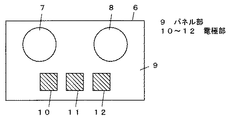
本実施の形態においては、実施の形態1、2、参考の形態1〜3に示したいずれか1つのタッチキーを調理器に用いたものである。すなわち、図に示した例は、調理器本体6は、そのパネル部9に2つの誘導加熱部7、8と、各実施の形態に示したいずれか1つの構成のタッチキー10、11、12とを有した電磁調理器を示している。そして、タッチキー11は設定温度の下降、タッチキー12は電源の入り/切り、タッチキー13は設定温度の上昇などの機能を有するものである。
In this embodiment, any one of the touch keys shown in
このように、本実施の形態における調理器は、各実施の形態1、2、参考の形態1〜3に示したいずれか1つの構成のタッチキーを調理器に用いることにより、回路構成が簡単にでき、コンパクトな調理器が得られ、安全性、使用性を高めることも可能である。 As described above, the cooker according to the present embodiment has a simple circuit configuration by using the touch key having any one of the configurations shown in the first and second embodiments and the first to third embodiments for the cooker. Therefore, a compact cooker can be obtained, and safety and usability can be improved.
以上のように、本発明にかかるタッチキーとそれを用いた調理器は、キーの数が増えても発振部と検知部の数を増加させる必要がなくなり回路構成が簡単にできるので、各種の機器、特に電磁調理器などのフラットパネルを有する機器にも適用できる。 As described above, the touch key and the cooker using the touch key according to the present invention do not need to increase the number of oscillation units and detection units even if the number of keys increases, and thus the circuit configuration can be simplified. The present invention can also be applied to equipment, particularly equipment having a flat panel such as an electromagnetic cooker.
1、9 パネル部
2〜4、10〜12 電極部
2a 穴
2b、3b タッチマーク
6 発振部
7 検知部
DESCRIPTION OF
Claims (1)
Priority Applications (1)
| Application Number | Priority Date | Filing Date | Title |
|---|---|---|---|
| JP2003393610A JP4168917B2 (en) | 2003-11-25 | 2003-11-25 | Cooker using touch keys |
Applications Claiming Priority (1)
| Application Number | Priority Date | Filing Date | Title |
|---|---|---|---|
| JP2003393610A JP4168917B2 (en) | 2003-11-25 | 2003-11-25 | Cooker using touch keys |
Publications (2)
| Publication Number | Publication Date |
|---|---|
| JP2005158390A JP2005158390A (en) | 2005-06-16 |
| JP4168917B2 true JP4168917B2 (en) | 2008-10-22 |
Family
ID=34719923
Family Applications (1)
| Application Number | Title | Priority Date | Filing Date |
|---|---|---|---|
| JP2003393610A Expired - Fee Related JP4168917B2 (en) | 2003-11-25 | 2003-11-25 | Cooker using touch keys |
Country Status (1)
| Country | Link |
|---|---|
| JP (1) | JP4168917B2 (en) |
Families Citing this family (1)
| Publication number | Priority date | Publication date | Assignee | Title |
|---|---|---|---|---|
| JP2007329090A (en) * | 2006-06-09 | 2007-12-20 | Nec Corp | Input device |
-
2003
- 2003-11-25 JP JP2003393610A patent/JP4168917B2/en not_active Expired - Fee Related
Also Published As
| Publication number | Publication date |
|---|---|
| JP2005158390A (en) | 2005-06-16 |
Similar Documents
| Publication | Publication Date | Title |
|---|---|---|
| US20180081480A1 (en) | Touch pressure detection module and apparatus | |
| TWI539318B (en) | Electronic device with multi-function sensor and method of operating such device | |
| CN109375818B (en) | Touch device and driving method thereof, and touch display device and driving method thereof | |
| KR101209514B1 (en) | Touch input device for detecting changes in the magnetic field and capacitance | |
| KR20130057637A (en) | Touch sensing apparatus | |
| TW201541314A (en) | System and method for gesture control | |
| US9916053B2 (en) | User interface unit, electronic device and manufacturing method | |
| TWI379225B (en) | Method for filtering out signals from touch device | |
| KR101473184B1 (en) | A capacitive touch screen for integrated of fingerprint recognition of swipe type | |
| KR20150006681A (en) | Touch screen to recognize a remote gesture and controlling method thereof | |
| JPH09237158A (en) | Touch panel device | |
| JP4168917B2 (en) | Cooker using touch keys | |
| JP4042653B2 (en) | Induction cooker with touch keys | |
| JP2005166392A (en) | Touch key, and electromagnetic cooker equipped with the same | |
| CN104077000B (en) | Touch panel and its driving method, display device | |
| JP6245641B2 (en) | Touchpad input device and touchpad control program | |
| JP2003224459A (en) | Touch key and electromagnetic cooker using the same | |
| JP2007122891A (en) | Touch key and electric apparatus using it | |
| JP4444260B2 (en) | Touch key and electromagnetic cooker having the same | |
| JP4616378B2 (en) | Touch panel | |
| JP2001306246A (en) | Touch pad | |
| JPS62147613A (en) | Input device | |
| CN105045431B (en) | Intelligence sensor and its touch detecting method for touch screen terminal | |
| KR20130104598A (en) | Home key apparatus for touch panel device | |
| CN111782074A (en) | Touch panel and electronic equipment |
Legal Events
| Date | Code | Title | Description |
|---|---|---|---|
| A621 | Written request for application examination |
Free format text: JAPANESE INTERMEDIATE CODE: A621 Effective date: 20050926 |
|
| RD01 | Notification of change of attorney |
Free format text: JAPANESE INTERMEDIATE CODE: A7421 Effective date: 20051013 |
|
| A977 | Report on retrieval |
Free format text: JAPANESE INTERMEDIATE CODE: A971007 Effective date: 20080414 |
|
| A131 | Notification of reasons for refusal |
Free format text: JAPANESE INTERMEDIATE CODE: A131 Effective date: 20080422 |
|
| A521 | Written amendment |
Free format text: JAPANESE INTERMEDIATE CODE: A523 Effective date: 20080620 |
|
| TRDD | Decision of grant or rejection written | ||
| A01 | Written decision to grant a patent or to grant a registration (utility model) |
Free format text: JAPANESE INTERMEDIATE CODE: A01 Effective date: 20080715 |
|
| A01 | Written decision to grant a patent or to grant a registration (utility model) |
Free format text: JAPANESE INTERMEDIATE CODE: A01 |
|
| A61 | First payment of annual fees (during grant procedure) |
Free format text: JAPANESE INTERMEDIATE CODE: A61 Effective date: 20080728 |
|
| FPAY | Renewal fee payment (event date is renewal date of database) |
Free format text: PAYMENT UNTIL: 20110815 Year of fee payment: 3 |
|
| FPAY | Renewal fee payment (event date is renewal date of database) |
Free format text: PAYMENT UNTIL: 20110815 Year of fee payment: 3 |
|
| LAPS | Cancellation because of no payment of annual fees |