JP4168182B2 - Overlapping embossing of stem mechanical fastener structure with cap - Google Patents
Overlapping embossing of stem mechanical fastener structure with cap Download PDFInfo
- Publication number
- JP4168182B2 JP4168182B2 JP50442199A JP50442199A JP4168182B2 JP 4168182 B2 JP4168182 B2 JP 4168182B2 JP 50442199 A JP50442199 A JP 50442199A JP 50442199 A JP50442199 A JP 50442199A JP 4168182 B2 JP4168182 B2 JP 4168182B2
- Authority
- JP
- Japan
- Prior art keywords
- stem
- web
- hook
- heated
- surface member
- Prior art date
- Legal status (The legal status is an assumption and is not a legal conclusion. Google has not performed a legal analysis and makes no representation as to the accuracy of the status listed.)
- Expired - Lifetime
Links
- 238000004049 embossing Methods 0.000 title 1
- 238000000034 method Methods 0.000 claims description 52
- 238000004519 manufacturing process Methods 0.000 claims description 13
- 230000007423 decrease Effects 0.000 claims description 8
- 238000010438 heat treatment Methods 0.000 claims description 6
- 238000003825 pressing Methods 0.000 claims description 4
- 229920005992 thermoplastic resin Polymers 0.000 claims description 3
- 239000000463 material Substances 0.000 description 52
- 239000002243 precursor Substances 0.000 description 24
- 238000000465 moulding Methods 0.000 description 23
- 229920005989 resin Polymers 0.000 description 10
- 239000011347 resin Substances 0.000 description 10
- 229920001169 thermoplastic Polymers 0.000 description 8
- 239000004416 thermosoftening plastic Substances 0.000 description 8
- 235000001674 Agaricus brunnescens Nutrition 0.000 description 6
- 238000010586 diagram Methods 0.000 description 6
- -1 polypropylene Polymers 0.000 description 5
- 239000004820 Pressure-sensitive adhesive Substances 0.000 description 4
- 230000015572 biosynthetic process Effects 0.000 description 4
- 239000000835 fiber Substances 0.000 description 4
- 229920001778 nylon Polymers 0.000 description 4
- 239000012815 thermoplastic material Substances 0.000 description 4
- 239000004677 Nylon Substances 0.000 description 3
- 239000004743 Polypropylene Substances 0.000 description 3
- 239000000853 adhesive Substances 0.000 description 3
- 230000001070 adhesive effect Effects 0.000 description 3
- 230000008901 benefit Effects 0.000 description 3
- 238000005304 joining Methods 0.000 description 3
- 239000012778 molding material Substances 0.000 description 3
- 229920000642 polymer Polymers 0.000 description 3
- 229920001155 polypropylene Polymers 0.000 description 3
- 239000000758 substrate Substances 0.000 description 3
- 230000008859 change Effects 0.000 description 2
- 239000011248 coating agent Substances 0.000 description 2
- 238000000576 coating method Methods 0.000 description 2
- 238000001816 cooling Methods 0.000 description 2
- 239000012530 fluid Substances 0.000 description 2
- 239000010410 layer Substances 0.000 description 2
- 239000000155 melt Substances 0.000 description 2
- 229920001343 polytetrafluoroethylene Polymers 0.000 description 2
- 239000004810 polytetrafluoroethylene Substances 0.000 description 2
- 230000037307 sensitive skin Effects 0.000 description 2
- XLYOFNOQVPJJNP-UHFFFAOYSA-N water Substances O XLYOFNOQVPJJNP-UHFFFAOYSA-N 0.000 description 2
- VGGSQFUCUMXWEO-UHFFFAOYSA-N Ethene Chemical compound C=C VGGSQFUCUMXWEO-UHFFFAOYSA-N 0.000 description 1
- 239000005977 Ethylene Substances 0.000 description 1
- 239000004952 Polyamide Substances 0.000 description 1
- 239000004698 Polyethylene Substances 0.000 description 1
- 229910000831 Steel Inorganic materials 0.000 description 1
- 241000270666 Testudines Species 0.000 description 1
- 239000004699 Ultra-high molecular weight polyethylene Substances 0.000 description 1
- 238000005299 abrasion Methods 0.000 description 1
- 230000002411 adverse Effects 0.000 description 1
- 229920006026 co-polymeric resin Polymers 0.000 description 1
- 230000006835 compression Effects 0.000 description 1
- 238000007906 compression Methods 0.000 description 1
- 238000007796 conventional method Methods 0.000 description 1
- 229920001577 copolymer Polymers 0.000 description 1
- 238000005520 cutting process Methods 0.000 description 1
- 230000003247 decreasing effect Effects 0.000 description 1
- 238000006073 displacement reaction Methods 0.000 description 1
- 230000000694 effects Effects 0.000 description 1
- 239000013013 elastic material Substances 0.000 description 1
- HQQADJVZYDDRJT-UHFFFAOYSA-N ethene;prop-1-ene Chemical group C=C.CC=C HQQADJVZYDDRJT-UHFFFAOYSA-N 0.000 description 1
- 238000001125 extrusion Methods 0.000 description 1
- 230000006872 improvement Effects 0.000 description 1
- 238000001746 injection moulding Methods 0.000 description 1
- 239000007788 liquid Substances 0.000 description 1
- 230000007774 longterm Effects 0.000 description 1
- 230000013011 mating Effects 0.000 description 1
- 230000007246 mechanism Effects 0.000 description 1
- 230000003287 optical effect Effects 0.000 description 1
- 239000004033 plastic Substances 0.000 description 1
- 229920003023 plastic Polymers 0.000 description 1
- 239000004014 plasticizer Substances 0.000 description 1
- 229920002647 polyamide Polymers 0.000 description 1
- 229920000728 polyester Polymers 0.000 description 1
- 229920000573 polyethylene Polymers 0.000 description 1
- 229920000139 polyethylene terephthalate Polymers 0.000 description 1
- 239000005020 polyethylene terephthalate Substances 0.000 description 1
- 229920000098 polyolefin Polymers 0.000 description 1
- 229920005606 polypropylene copolymer Polymers 0.000 description 1
- 239000004800 polyvinyl chloride Substances 0.000 description 1
- 229920000915 polyvinyl chloride Polymers 0.000 description 1
- 239000010959 steel Substances 0.000 description 1
- 238000003860 storage Methods 0.000 description 1
- 238000010998 test method Methods 0.000 description 1
- 229920000785 ultra high molecular weight polyethylene Polymers 0.000 description 1
- 230000037303 wrinkles Effects 0.000 description 1
Images


Classifications
-
- A—HUMAN NECESSITIES
- A44—HABERDASHERY; JEWELLERY
- A44B—BUTTONS, PINS, BUCKLES, SLIDE FASTENERS, OR THE LIKE
- A44B18/00—Fasteners of the touch-and-close type; Making such fasteners
-
- A—HUMAN NECESSITIES
- A44—HABERDASHERY; JEWELLERY
- A44B—BUTTONS, PINS, BUCKLES, SLIDE FASTENERS, OR THE LIKE
- A44B18/00—Fasteners of the touch-and-close type; Making such fasteners
- A44B18/0069—Details
- A44B18/0073—Attaching means
-
- A—HUMAN NECESSITIES
- A44—HABERDASHERY; JEWELLERY
- A44B—BUTTONS, PINS, BUCKLES, SLIDE FASTENERS, OR THE LIKE
- A44B18/00—Fasteners of the touch-and-close type; Making such fasteners
- A44B18/0046—Fasteners made integrally of plastics
- A44B18/0061—Male or hook elements
-
- A—HUMAN NECESSITIES
- A44—HABERDASHERY; JEWELLERY
- A44B—BUTTONS, PINS, BUCKLES, SLIDE FASTENERS, OR THE LIKE
- A44B18/00—Fasteners of the touch-and-close type; Making such fasteners
- A44B18/0046—Fasteners made integrally of plastics
- A44B18/0061—Male or hook elements
- A44B18/0065—Male or hook elements of a mushroom type
-
- B—PERFORMING OPERATIONS; TRANSPORTING
- B29—WORKING OF PLASTICS; WORKING OF SUBSTANCES IN A PLASTIC STATE IN GENERAL
- B29C—SHAPING OR JOINING OF PLASTICS; SHAPING OF MATERIAL IN A PLASTIC STATE, NOT OTHERWISE PROVIDED FOR; AFTER-TREATMENT OF THE SHAPED PRODUCTS, e.g. REPAIRING
- B29C43/00—Compression moulding, i.e. applying external pressure to flow the moulding material; Apparatus therefor
- B29C43/22—Compression moulding, i.e. applying external pressure to flow the moulding material; Apparatus therefor of articles of indefinite length
- B29C43/222—Compression moulding, i.e. applying external pressure to flow the moulding material; Apparatus therefor of articles of indefinite length characterised by the shape of the surface
-
- B—PERFORMING OPERATIONS; TRANSPORTING
- B29—WORKING OF PLASTICS; WORKING OF SUBSTANCES IN A PLASTIC STATE IN GENERAL
- B29C—SHAPING OR JOINING OF PLASTICS; SHAPING OF MATERIAL IN A PLASTIC STATE, NOT OTHERWISE PROVIDED FOR; AFTER-TREATMENT OF THE SHAPED PRODUCTS, e.g. REPAIRING
- B29C43/00—Compression moulding, i.e. applying external pressure to flow the moulding material; Apparatus therefor
- B29C43/32—Component parts, details or accessories; Auxiliary operations
- B29C43/44—Compression means for making articles of indefinite length
- B29C43/46—Rollers
- B29C2043/461—Rollers the rollers having specific surface features
-
- Y—GENERAL TAGGING OF NEW TECHNOLOGICAL DEVELOPMENTS; GENERAL TAGGING OF CROSS-SECTIONAL TECHNOLOGIES SPANNING OVER SEVERAL SECTIONS OF THE IPC; TECHNICAL SUBJECTS COVERED BY FORMER USPC CROSS-REFERENCE ART COLLECTIONS [XRACs] AND DIGESTS
- Y10—TECHNICAL SUBJECTS COVERED BY FORMER USPC
- Y10T—TECHNICAL SUBJECTS COVERED BY FORMER US CLASSIFICATION
- Y10T24/00—Buckles, buttons, clasps, etc.
- Y10T24/27—Buckles, buttons, clasps, etc. including readily dissociable fastener having numerous, protruding, unitary filaments randomly interlocking with, and simultaneously moving towards, mating structure [e.g., hook-loop type fastener]
- Y10T24/2767—Buckles, buttons, clasps, etc. including readily dissociable fastener having numerous, protruding, unitary filaments randomly interlocking with, and simultaneously moving towards, mating structure [e.g., hook-loop type fastener] having several, repeating, interlocking formations along length of filaments
-
- Y—GENERAL TAGGING OF NEW TECHNOLOGICAL DEVELOPMENTS; GENERAL TAGGING OF CROSS-SECTIONAL TECHNOLOGIES SPANNING OVER SEVERAL SECTIONS OF THE IPC; TECHNICAL SUBJECTS COVERED BY FORMER USPC CROSS-REFERENCE ART COLLECTIONS [XRACs] AND DIGESTS
- Y10—TECHNICAL SUBJECTS COVERED BY FORMER USPC
- Y10T—TECHNICAL SUBJECTS COVERED BY FORMER US CLASSIFICATION
- Y10T24/00—Buckles, buttons, clasps, etc.
- Y10T24/27—Buckles, buttons, clasps, etc. including readily dissociable fastener having numerous, protruding, unitary filaments randomly interlocking with, and simultaneously moving towards, mating structure [e.g., hook-loop type fastener]
- Y10T24/2775—Buckles, buttons, clasps, etc. including readily dissociable fastener having numerous, protruding, unitary filaments randomly interlocking with, and simultaneously moving towards, mating structure [e.g., hook-loop type fastener] having opposed structure formed from distinct filaments of diverse shape to those mating therewith
-
- Y—GENERAL TAGGING OF NEW TECHNOLOGICAL DEVELOPMENTS; GENERAL TAGGING OF CROSS-SECTIONAL TECHNOLOGIES SPANNING OVER SEVERAL SECTIONS OF THE IPC; TECHNICAL SUBJECTS COVERED BY FORMER USPC CROSS-REFERENCE ART COLLECTIONS [XRACs] AND DIGESTS
- Y10—TECHNICAL SUBJECTS COVERED BY FORMER USPC
- Y10T—TECHNICAL SUBJECTS COVERED BY FORMER US CLASSIFICATION
- Y10T24/00—Buckles, buttons, clasps, etc.
- Y10T24/27—Buckles, buttons, clasps, etc. including readily dissociable fastener having numerous, protruding, unitary filaments randomly interlocking with, and simultaneously moving towards, mating structure [e.g., hook-loop type fastener]
- Y10T24/2792—Buckles, buttons, clasps, etc. including readily dissociable fastener having numerous, protruding, unitary filaments randomly interlocking with, and simultaneously moving towards, mating structure [e.g., hook-loop type fastener] having mounting surface and filaments constructed from common piece of material
Description
技術分野および発明の背景
本発明は、直立したステム部分にキャップを付与してメカニカルファスナフックを形成する方法および装置に関する。本発明は特に、均一性および製造性に優れた、非対称なキャップを有するフック形状の形成方法に関する。
フックアンドループ型メカニカルファスナは広範囲の製品群および用途に用いられている。これらのフックアンドループ型メカニカルファスナにおいて使用するフック材料の形成する方法はさまざまである。長年の間に、フックが嵌入するループ材料との係合メカニズムおよび特性はそのフックおよび/またはループに依存して異なることがわかっている。このため、特定のフック成形技術を実際に適用可能できる範囲はいずれも、特定の種類にしか使用できない、あるいは特定の種類のループ材料としか嵌合できないフックの製造に制約されてしまう。
初期のフック材料の中には、直立したナイロン繊維の特異な経糸を切断して端部開口型ナイロンフックおよび機能を持たない直立ステムを形成するという米国特許第2,717,437号および同第3,009,235号に説明された加工により形成されたものもある。これらの種類の方法により形成されたフックは大型(例えば約2mm)であるため、大量の開口パイルループ材料を使用する必要があり、単位面積当たりのフック数はかなり少なくなる。これらのフック類はまた肌触りが粗いため、フックが敏感な皮膚に触れることの多い使用にはあまり適していない。この種類のフックは長期使用に耐えるため、現在でも今だ使用されている。類似した種類のフック構造は、浅いJ型ダイを用いて熱可塑性材料を直接J型「くくり」フックに形成する米国特許第3,594,865号の方法により形成される。これらの「くくり型」は成形材料の連続ループに形成されて押出機を通過する。押出機により、くくり型成形材料の真下に位置する繊維ウェブを含浸させながら、ナイロンなどの溶融プラスチックをくくり型に成形する。押出機から排出される際、余計な熱可塑性樹脂をくくり型成形材料の表面から除去する。凝固したばかりのフックおよび支持体をくくり型成形から本質的に引っ張るだけでその型を取り外すと、弾性フックが支持体上に残留する。米国特許第3,594,863号は、フック載置帯片を製造する類似装置に関する。これら双方の特許には、そこに説明された方法によりさまざまな形状を有するフックを製造できることが述べられている。米国特許第3,594,865号において、フックを直接射込み成形する従来の方法ではその形状が基部から先端にかけて先細りする形状に制約されてしまうことが述べられている。しかしながら、これらの特許により形成されるフックの形状は比較的大きいため、外側表面からフックの長手方向にそって反対側の表面に向けて先細りしていなければならない。
米国特許第3,594,865号に言及されている従来の成形型フック形状は、米国特許第4,984,339号および同第5,315,740号に記載の種類と同様である。これらの特許には、内側の平滑な略凹面と略凸面形状の外面とにより規定される外形を有して成形されたJ型フックが開示されている。このフックはフック基部からフック自由端に向けて滑らかに連続的にその幅が先細りになっている。このフックは、剪断状態にあってもあるいは所望の圧力を加えてもフックに係合したループの解放時に変形しないように設計されていると言われている。後者特許には、フック先端を規定する領域の変位量が少ない類似フックが開示されている。これは使い捨てオムツなどの適用における使用に望ましいと説明されている。これらのJ型フックはほぼ適切な性能を有する材料であるが、製造が極めて難しく、第5,315,740号に説明されているように非常に小型フックを製造する場合は特に難しい。小型で複雑な形状を有する成形用キャビティの製造は非常に難しく、形成するフックの寸法がとりわけ小さければ、それに比例してJ型フック成形キャビティを多数形成しなければならない。成形用キャビティが小型で複雑な形状であればより一層目詰りしやすく、摩損により成形用キャビティの形状が崩れやすくなる。
非常に融通性があり低コストな、広範囲の寸法および形状を有するフックの形成方法が米国特許出願第08/723,632号ばかりでなく国際特許出願第WO94/23610および同92/04839号に説明されている。これらの特許および特許出願に説明された方法を用いる際、数多くの直立した熱可塑性ステムを有する支持体を例えば2つのカレンダーロールにより形成されたニップ間の間隙内に給送する。上部ニップは滑らかで加熱しておくことにより、ステムの末端あるいは先端を加熱および機械的圧力により変形し、選択したニップ条件と、ニップ内のステムの相対速度と、ステムの寸法および形状とに依存してさまざまな種類のキャップ構造を形成する。変形を受けなかったステム部分と形成されたキャップ部分とがフック構造をなす。プリカーサ材料である、直立の変形を受けていない熱可塑性ステムを有する支持体の形成には成形技術を用いることができる。しかしながら、ステムが直立した形状であれば、成形用キャビティの形成および使用もJ型フック成形に比較してかなり単純であり問題も少ない。例えば、これらの単純な成形用キャビティ形状では、成形材料をうまく選択すれば目詰りを起こす、あるいは摩損による悪影響を受けることは格段に減少する。さらに、この方法と用いた場合、単位面積当たりに数多くの小型フックが密集していても、その形成は比較的容易であることがわかっており、これは比較的弾性が低い織物あるいは不織ループ材料との係合に特に望ましい。これらの低弾性材料は一般に安価であるため、使い捨て衣類などの低コストでなければならない使用用途にこのフック構造は非常に望ましいことになる。これらのフック材料の感触も利点の1つである。フックが高密度であるため、および/またはフックが比較的平坦あるいは平らな上面を有するため、このフックは肌に非常に優しく滑らかで薄膜のような質感である。好適なフック材料は、フックがさりげなく皮膚に接触しても本質的に気づきもしないものである。このため、このフックは皮膚の近接にて使用する使い捨て衣類(例えばオムツあるいは手術用ガウン)に有用となる。本発明の目的は、フックを形成する上述の方法およびそれにより形成されるフックを改良することである。
本発明の簡単な要約
本発明のキャップ付ステムメカニカルファスナの形成方法において、ウェブ状支持体の少なくとも1表面から遠方に向けて突出する一連の直立した熱可塑性ステムを有するプリカーサウェブ材料を準備する。この直立したステムは一般に、その縦方向に実質的に一定の幅を有するが、基部から先端にかけて先細り状であってもよい。加熱した表面部材を支持面部材の反対側に位置付けてニップを形成する。このニップはウェブあるいは直立したステムを有する支持体面の全横幅に、また圧搾領域が形成できるだけの指定距離をウェブの縦に沿って延在することが好ましい。プリカーサウェブを、間隙を設けたニップ内に給送する。この間隙は圧搾領域内において所与の初期幅から先細りする。ステム先端をまず所与の入口間隙幅において係合し、所与の終端間隙幅にニップ内で圧搾する。このニップにより圧搾領域において順次、重合体ステムを加熱したニップ表面部材と支持面部材との間で係合および圧搾する。連続的に圧搾することが好ましいが、間隙幅により特定した圧搾領域内において圧搾を中断する、および/または異なる圧搾速度で圧搾することも可能である。このように加熱および圧搾することにより、直立した熱可塑性ステムの末端部を、繊維ループ材料を係合できるキャップ構造に変形する。
圧搾領域の少なくとも一部において、加熱したニップ部材の表面に少なくとも一連のあるいは1組の横方向に間隔を置いた細長い峰部および谷(溝)部構造を設ける。この時、谷部深さに対する峰部高さの平均は一般に5〜500ミクロンであり、10〜200ミクロンであれば好ましく、15〜150ミクロンであれば最も好ましい。隣接する峰部構造の平均間隔は、ニップ内で変形する前のステム端部に直ちに隣接するステム基部の平均幅より狭い。各ステム端部が変形を受ける間に少なくとも2つの好ましくは4つの水平方向に間隔を置いた峰部構造に接触するように、峰部構造の間隔をあけることが好ましい。横方向に間隔を置いた峰部および谷部構造の所与の1組は、少なくとも隣接する直立ステム部材間の平均距離(少なくとも2方向における最も近接する隣同士の距離平均距離)に匹敵するだけの距離を長手方向に、好ましくは圧搾領域内の加熱されたニップ部材の長さに沿って連続的に延在することが好ましい。1組の隣接する峰部および谷部構造が横方向に少なくとも隣接する直立ステム部材間の平均距離(少なくとも2方向における最も近接する隣同士の距離平均距離)に匹敵するだけの距離を延在するように、所与の1組には同様に充分な峰部および谷部構造を設ける。この峰部および谷部構造を加熱したニップ部材上に配置することにより、機能性を損なうことなくウェブの縦横にわたり、方向性および、構造に依存してフック頭部形状の均一性が改良され、高弾性あるいは低弾性不織ループ材料に対する係合性を一般に強化したキャップ付ステムフックを得られる。
さらに、プリカーサウェブにウェブ状支持体から突出して直立した熱可塑性ステムの配列にキャップを付与する装置の提供も本発明の目的である。この装置はニップを形成する支持面部材の反対側に加熱された表面部材を含み、このニップは、圧縮領域を規定する入口間隙幅から終端間隙幅にかけて実質的に連続的に先細ることが好ましい。給送手段を設けてプリカーサウェブをニップ内に給送して通過させる。ニップの加熱された表面部材に、上述のように少なくとも圧搾領域の一部において峰部および谷部構造を設ける。
ニップ間隙の幅は圧搾領域において連続的に減少することが好ましいが、少なくとも一部の縦沿いに略一定の間隙幅を有する、断続的に減少および増加する、異なる割合で減少する、あるいはこれらの組み合わせのいずれであってもよい。一般に、ニップ圧搾領域を、第1の入口間隙幅と、好適には第1の間隙幅未満であるニップ終端間隙を規定する第2の間隙とにより規定する。所与のニップ入口間隙幅を、プリカーサウェブ材料のステム先端がまず、ニップを規定する加熱された上面に圧搾されて係合する地点における支持体基材ウェブの厚さと直立ステムの平均高さとにより規定する。終端間隙幅はニップ内で最も狭い間隙幅であり、この地点を超えるとウェブおよび変形を受けたステム先端部あるいは端部は加熱されたニップ表面部材との圧搾された係合状態を実質的に離脱する。
本発明の方法および装置により、キャップ付ステムを備えたメカニカルファスナフックを形成する従来技術による方法に説明されている利点のすべてを備えながら、熱可塑性ステムの末端部を、非対照なキノコ型頭部、長細いJ型フック、T型フックなどを含むいずれの所与方向への配向も可能なさまざまな非対照のキャップ形状に形成することが出来る。
【図面の簡単な説明】
図1は、本発明のキャップ付ステムファスナ製造用の直立ステムを有する材料片を製造する方法を示す略図である。
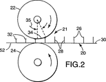
図2は、カレンダーシステムを用いたキャップ製造方法を示す略図である。
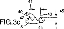
図3aおよび図3bは、カレンダーロール上にある例えば図3cに示すキャップ製造表面の峰部および谷部ミクロ構造の配向を示す略図である。
図4は、本発明による有頭ステムファスナを形成する別の装置を示す略図である。
図5は、本発明による有頭ステムファスナを形成する別の装置を示す略図である。
図6は、本発明の方法に用いる支持体料を備えたステムの側面図である。
図7は、例えば本発明の方法により製造された有頭ステムファスナの側面図である。
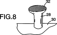
図8は、本発明の方法により製造された有頭ステムファスナの斜視図である。
図9は、本発明の方法により製造された有頭ステムファスナの光学写真である。
好適実施例の詳細な説明
本発明の方法は、フックアンドループ型メカニカルファスナシステムあるいは嵌合型自己係合メカニカルファスナにおいて使用する有頭あるいはキャップ付ステムメカニカルファスナの形成に関する。
本発明の目的はまず、少なくとも以下に説明するステップを含む、支持体のフック頭部にキャップを付与する方法を提供することである。
まず、実質的に直立した突起の配列を備えたウェブ状支持体であるウェブを準備する。この突起は、実質的に直立したステム基部とステム端部あるいはフック頭部とにより構成される。総体的に、このウェブは第1の平均厚さを有する。
さらに、少なくとも1枚の第1の加熱された表面部材と少なくとも1枚の第2の反対側に位置する表面部材とを有するニップを準備する。ニップには、第1の入口間隙幅と第2の終端間隙幅とにより規定される圧搾領域を含む間隙を設ける。第1の間隙幅は実質的に上記のウェブ第1の平均厚さ以下である。第2の終端間隙幅は第1のウェブ厚さ未満であり、ニップ内で最も狭い間隙幅である。少なくとも1枚の加熱された表面部材に、圧搾領域内において少なくとも1方向に長手方向に延在する少なくとも1組の峰部および谷部構造を設ける。隣接する峰部構造間の平均間隔は一般に、ステム端部あるいはフック頭部に直ちに隣接するステム基部の平均幅未満である。また、少なくとも1組の峰部および谷部構造は一般に、隣接する直立ステム基部間の平均距離に少なくとも匹敵する距離を長手方向に延在する。
次いで、ウェブを第2の方向に圧搾領域内を通過するようにウェブ通路に沿って移動し、実質的に直立した突起の配列の少なくとも一部を、少なくとも1組の峰部および谷部構造により規定される少なくとも第1の方向に加熱された表面部材により優先的に変形する。
この第1の方向を第2の方向と実質的に平行にすることが可能であり、この場合加熱された表面部材およびウェブの相対速度は同じであっても異なってもよい。フック頭部を加熱された表面部材により形成あるいは修正して、ウェブが移動する方向に配向する。第1および第2の方向が実質的に異なる場合、加熱された表面部材およびウェブの相対速度は一般に実質的に同じである。同様に、同一の加熱された表面部材上に1組以上の峰部および溝部構造を設けた場合、その構造の複数組を実質的に異なる方向に配向して、加熱された表面部材をウェブと同じ相対速度で移動しなければならない。
キャップ付あるいは有頭ステムフックファスナを、直立した可塑的に変形可能な熱可塑性ステムの配列を有する支持体料を用いて形成することができる。これらの直立ステムを、同一の熱可塑性材料からなる一体成形支持体上に形成することが好ましい。適した熱可塑性材料の例として、ポリプロピレンあるいはポリエチレンなどのポリオレフィン、ナイロンなどのポリアミド、ポリ(エチレンテレフタレート)などのポリエステル、軟質ポリ塩化ビニル、任意に他のポリマーあるいは可塑剤を含むこれらのコポリマーおよび配合物などを挙げることが出来る。
直立した突起配列を有するウェブ状支持体であるこのプリカーサ材料の適した形成方法を図1に示す。予め選択した熱可塑性樹脂の給送流4を従来の手段により押出機6内に給送し、樹脂を溶解した後、加熱された樹脂をダイ8に移動する。ダイ8は幅広リボン形状材料として樹脂を、細長い穴の形状である成形キャビティ配列12を有するシリンダーなどの成形面10に押出す。この時、キャビティは先細り状となって凝固した樹脂を成形キャビティから剥離しやすいことが好ましい。これらの穴あるいは成形キャビティは直線状の(すなわち縦方向に縦軸が1本のみ)キャビティであることが好ましい。成形キャビティを真空システム(図示せず)に接続して樹脂を成形キャビティに流入させることが可能である。これにはドクターあるいはナイフを用いて成形シリンダーの内部表面に押出された余分な材料を除去する必要がある。成形キャビティ12の配置は液体樹脂を投入する開口端部と閉鎖端部とを有する成形面内のみとすることが好ましい。この場合、真空システム14を用いて、ダイ8に投入する前に成形キャビティ12を少なくとも部分的に吸い上げることが出来る。成形面10をダイ8の表面に継ぎ合わせて、余分な樹脂が例えばダイ側縁部などに押し出されないように接触させる。一体形成された支持体および直立ステムをストリッパロール18などにより成形面から引き抜く前に、成形面およびキャビティを空冷あるいは水冷などにより冷却することができる。こうして熱可塑性材料からなる直立ステム28を一体成形して有する支持体30のウェブ20を得る。別の方法として、押出成形あるいは他の周知の技術により、予備形成された支持体などの上に直立ステムを形成することも可能である。
図1の方法あるいは同様の方法により形成したステムに、図2に示すように2つのカレンダーロール22および24により形成することが出来る加熱されたニップを用いてキャップを付与することが出来る。加熱したカレンダーロール22は、支持体30から上方に突出したステム28の末端部26の予め定められた部分に接触する。圧搾領域35において樹脂をロール22の表面に粘着させることなくニップの加圧により末端部26を容易に変形することができるように、ロールの温度を設定する。ロール22表面に高温に耐性を有する剥離コーティングを施して、ステム先端あるいは末端部26と加熱ロール22とを高温になるまで加熱する、および/または長時間接触させることを可能にしてもよい。
本発明の方法において、例えば加熱されたロール22の表面に一連の谷部あるいは溝部40およびそれを分離する峰部42を設ける。溝の幅41は峰部42あるいは峰部42の縁部43により規定され、さらに溝40の低地点44により溝深さ45を規定する。図3cに示すように、峰部42に先端を規定して設けることは可能であるが、峰部頂部は平坦であっても曲線状であっても、あるいはさらなるミクロ構造を有していてもよい。同様に、溝部は略V溝として図示しているが、U型、矩形、W型、あるいは他の形状であってもよい。複数組の峰部および溝部を連続的あるいは断続的に、横軸方向にあるいは縦軸方向に、あるいは中間角度で延在させることが出来、あるいは峰部および溝部のさまざまな組み合わせを異なる方向に延在させることも可能である。溝部40の平均深さ45は一般に5〜500ミクロンであり、10〜200ミクロンであれば好ましい。溝の深さは一般に、末端部26の加熱されて軟化した樹脂の流入を方向付けられるほど充分な深さににしなければならない。平均溝幅41は、ステム28の末端部26の平均幅より狭いことが好ましい。平均溝幅41は一般に、末端部26が変形を受ける際に2〜40個の溝、好ましくは4〜20個の溝に接触するように設定する。溝の深さおよび幅は均一であることが好ましいが、所望によりかなりの変化を持たせてもよい。例えば、溝の全長沿いにその深さを増加あるいは減少することが可能である。最も浅い溝深さでも少なくとも15ミクロンであることが好ましい。
同様に、峰部の高さは実質的に均一にする。しかしながら、峰部の高さを変化させることも可能であり、場合によっては1つあるいは複数の峰部について第2の交差方向溝あるいは他の溝を用いることもできる。第2の交差溝は、キャップ製造加工中のより複雑なフローパターンを提供する、および/または隣接する第1の溝間に樹脂をより均等に配置するために有用である。第1の溝により、ニップ21内において加熱され軟化したステム頂部の流れを方向付け、あるいは変形して、ステムの変形を受けた末端部26からさらに非対称の頭部32を形成することができる。キャップを有する頭部をこのようにさらに非対称にすることにより(対称面の数の削減)、大半の繊維ループ材料との係合力を改良できる。これは一般に、頭頂部の平坦部分あるいは平面部分の合計断面面積を増加することなく、頭部の張出部分を増加することにより実現可能である。ニップ内において平滑な加熱された表面部材を用いる従来技術による方法では、キャップ頭部のステムを超えた張出部分が増加すれば、比例的にキャップ頂部の平坦面部分が増加したため、ループ材料への嵌入がうまく行かなかった。
このように非対称性を改良することは、所与ステムの2つの対向側部上に張出部分を備えたフックを提供できるという点において特に有利である。キャップ付頭部をいずれの特定方向あるいは複数の方向に向けることも容易に実現でき、これは従来技術による方法では得られなかった、あるいは得られたとしても非常に困難であった大きな利点である。さらに本発明によるキャップ製造方法を用いて、先に形成されたフック頭部に方向性を持たせる、あるいはフックファスナ用張出部分を設けることができる。これらのフック頭部は、キャップ製造加工あるいは成形などの他の周知技術を用いて形成することが出来る。唯一の要件は、以下に規定するようにフックを実質的に直立するステム上に形成するということである。この場合、隣接する峰部間の平均間隔は、峰部および溝部の長さ方向に垂直な方向においてフック頭部の幅未満とする。
図6および図7に示すように、本発明の加工により、キャップ付頭部を容易に、例えば係属中である米国特許出願第08/723,632号に開示されているJ型に形成することが出来る。本方法において、J型フック106の寸法として、フックの平面頂部の合計表面面積ばかりでなく、プリカーサステム28の高さ110、ステム直径114、最終的なフックの高さ118、フック間の距離120、フック開口部の幅122、フック開口部の高さ124、フック頭部106の基部上に位置するフック頭部の厚さ128、フック頭部の高さ129、およびフック張出部109がある。ステム末端部を、変形を受けないステム基部であるステム残部を含む26として図示する。フィルム厚さあるいは支持体厚さ132がさらにフック片を規定する。同じ寸法の組み合わせはキノコ型、傘型、T型などを含む他のフック頭部形状にも見られる。キノコ型、傘型、T型などの形成において、ロール22の相対速度はウェブ30の相対速度に実質的に匹敵する。J型フックの形成には、支持体あるいはウェブ30を例えば加熱されたロール22とは異なる速度(すなわち、より速くあるいはより遅く、または反対方向に)で移動する。
本発明のキャップ付ステムファスナを製造する別の方法(例えば図4および図5)は、係属中の米国特許出願第08/781,783号に開示されている。図4の方法および装置において、キャップ製造装置50を用いて、複数の略均一なフック32を有するキャップ付ステムファスナ52を形成する。裏面58を有する支持体30と正面53から遠方に突出している複数の重合体ステム28とを備えたプリカーサウェブ20をニップ入口64に方向付ける。ニップ入口64を加熱されたロール66と曲線状支持構造物68との間に形成する。曲線状支持構造物68の形状は加熱されたロール66の形状に、それより僅かに大きな半径の曲率で略対応していることが好ましい。ピストン80により、曲線状支持構造物68と加熱されたロール66との間に圧搾力を発生する。
ニップ64において、ニップ入口72における第1の入口間隙幅と、圧搾領域75を規定するニップ出口76における第2の終端間隙幅とを規定する。第2の終端間隙幅を第1の間隙幅より狭くすることが好ましい。好適実施例において、ニップ64の間隙幅は、少なくとも一部領域において、実質的に一次変化率で連続的に減少する。間隙幅におけるこの実質的な一次変化率は、ニップ入口72とニップ出口76との間の少なくともニップ入口間隙に直ちに隣接する領域に当てはまることが好ましい。別の実施例(図示せず)において、ニップ64は、ニップ入口72とニップ出口76との間のある中間地点で最小値まで減少する、あるいは減少した後増加し、再度減少するなどの場合もある。
空気あるいは水などの流体を、パイプ78を介して支持体30の背面58と表面116との間の界面に導入し、流体圧力を発生してもよい。表面116を任意に、ポリ四フッ化エチレン(PTFE)あるいは超高分子量ポリエチレンなどの低表面エネルギ物質でコーティングしてもよい。空気圧力がない場合、支持体30はニップ64に突入後しわを寄せる傾向にあり、支持体30の引裂の原因となり得る。ピストン80を設けることにより、曲線状支持構造物68を加熱されたロール66に相対的に位置付ける。曲線状支持構造物68を枢支点82沿いに枢動させ、圧搾領域75内のニップ64の間隙幅をさらに調節してもよい。
加熱されたロール66とプリカーサウェブ20のライン速度との相対速度により、キャップ付ステムファスナ52のキャップ付ステムフック32の総体形状が決定する。加熱されたロール66の回転速度は、プリカーサウェブ20のライン速度より速い、遅い、あるいは同じのいずれであってもよい。用途により、プリカーサウェブ20がニップ内を移動している間、ロール66を静止する場合もある。別の方法として、ロール66をプリカーサウェブ20の移動方向とは反対方向に回転する場合もある。
図5は別の実施例によるキャップ付ステムファスナ96を形成するための方法および装置を示す。対向する複数のベルト92および94はニップ90を規定する細長い部分を有する。加熱源93によりベルト92の温度を所望通りに維持する。加熱されたベルト92をベルト94に対して斜めに配置することにより、ニップ90を連続的に狭める。プリカーサウェブ20をニップ90に給送し、ステム28を圧搾して、圧搾領域95内において対向するベルト92および94の間に係合する。加熱と機械力とにより、ステム28を変形して、複数のキャップ付ステムフック98を備えた有頭ステムファスナ96を形成する。
ベルト92および94の相対的ライン速度がほぼ同じになるように、ベルト92および94を同期移動することが好ましい。ベルト92および94を同時に移動することにより、キャップ付ステムフック頭部98をステムに対してより対称(すなわち、2枚以上の対称面について略対称)に形成することが好ましい。しかしながら、完全に対称なキャップ付頭(すなわち円形キノコ型キャップ)を得ることできない。別の方法として、ベルト92および94の相対移動をわずかに非同期にすることにより、J型フックなどのステム(すなわち反射面は1枚以下)に対して非対称なキャップ付頭部98を形成することができる。静止した支持構造物をベルト94の代りに用いることも可能であり、この場合支持構造物は上述した空気圧力などの低摩擦表面を備えることが好ましいことを理解されたい。
フック32のキャップ付頭部の具体的な形状および方向を、加熱された表面部材および形成された間隙の温度および形状ならびに圧搾領域の長さばかりでなく、加熱された表面部材上の峰部および溝部の相対的な寸法、間隔、および方向と、ウェブ20および加熱された表面部材の相対速度とにより特定する。溝部は加熱された表面部材上において連続的かつ均一であることが好ましい。ロールを示す図3bのように、溝の方向は機械方向あるいは圧搾領域におけるニップ内でのウェブ移動方向であってもよい。これによりステム頭部は交差方向より機械方向に長くなり、この形状はおよそ図8の略図に示すように仕上がる。
溝部をウェブ移動方向に配向して用いる場合、機械方向にその溝深さに変化を持たせると、対称なキャップ付頭部は異なった度合いで伸長し、非対称なキャップ付頭部は、最も浅い溝深さに略対応する浅い溝深さを有することになる。対称なキャップ付頭部は、異なる伸長部あるいはステムが接触する溝深さに依存するアスペクト比を有することになる。非対称型なキャップ付頭部に関しては、ウェブおよび加熱された表面が異なる速度で移動するため、より浅い溝領域が総体的に溝深さをならしてしまうことなる。
加熱された表面部材上の溝部の角度を機械方向あるいはウェブ移動方向(例えばロールを示す図3aに図示)に相対的に方向付けることも、あるいは同じ加熱された表面部材上にあるいは異なる加熱された表面部材上に異なる配向の峰部および溝部の複数組を設けることも可能である。峰部および溝部の向きが機械方向に対応する場合、仕上がるキャップ付頭部にはウェブの縦方向に対応する角度で細長い複数の軸線が設けられ、これは複雑な製造技術を伴わずに平滑な加熱された表面ロールを用いる従来技術による方法では得られない特徴である。しかしながら、峰部および溝部の向きが機械方向に対応する場合、ウェブと加熱された表面部材との相対速度を実質的に同じにして、峰部がステムを削り取るあるいはそり落とすことがないようにしなければならない。複数組の峰部および溝部の機械方向に対する角度は0°を超えて最大180°まで可能であり、この角度を、例えば溝が曲線状、円形などであって直線状ではないことなどにより変化することができる。
峰部および溝部を圧搾領域の一部にのみ設けることも可能であり、複数枚の加熱された表面部材により複数の圧搾領域を形成してこれを実施しても、あるいは1枚の加熱された表面を1つの圧搾領域に用いて峰部および溝部をその圧搾領域にのみ設けて実施してもよい。各ステムが確実に峰部および溝部を備える圧搾領域の少なくとも一部と相対するように、表面部材を静止するか、ステムが峰部および溝部を有する少なくとも一部と接触する速度で移動するかのいずれかでなければならない。このようにキャップを有するステム上に形成された縁部あるいは溝を、所望により、峰部および谷部を備える加熱された表面部材あるいは領域に引き続く平滑な加熱された表面部材あるいは領域により、次いで平らにするあるいは削除してもよい。
総体的に、キャップを有するステムファスナフックは、支持体基材から約90°の角度で実質的に直立したステム基部の形状であるが、この角度は80°〜100°までの範囲が可能であり、85°〜95°が好ましい。キャップ付頭部はステムの末端部26から形成され、一般に少なくとも1つの、好ましくは2〜40個の、最も好ましくは4〜20個の肉薄領域あるいは溝(加熱された表面部材峰部により形成された)を有する略平坦かつ平らな上面を備える。キャップ付頭部は、その肉薄領域あるいは溝の方向に細長く、溝方向から見た頭部の縦横アスペクト比は約1:1:1、好ましくは少なくとも1:4:1、最も好ましくは1:5:1である。この略平坦あるいは平らな上面は、使い捨て衣類あるいは限定使用衣類に用いられる比較的開口した織物および不織ループ製品の係合に非常に適している。この平坦あるいは平らな上面は、一般に明確な先端部(例えば峰部から少なくとも2方向に伸びたフック斜面上の)を有して成形されたフックとは異なり、粗くなく触感的に肌触りが滑らかである。先の尖ったフックファスナは肌を刺激するため、敏感な肌に接触する使用(例えば赤ちゃん用オムツ)にはあまり適さない。
オムツなどの衣類に使用するため、キャップ付ステムフックの高さを均一にし、その高さは約0.10〜1.3mmであることが好ましく、約0.2〜0.5mmであれば最も好ましい。キャップを有するステムフックの支持体上の密度は、1cm2あたり60〜1600個のフックが好ましく、1cm2あたり100〜700個のフックであればより好ましい。キャップ付ステムフックの頭部に隣接するステム基部の直径は0.07〜0.7mmが好ましく、約0.1〜0.3mmであればより好ましい。キャップ付頭部はステム基部から少なくとも1つの側に垂直に平均で約0.01〜0.3mm、より好ましくは平均で約0.02〜0.25mm突出し、その外側と内側との間の平均厚さ(すなわちステムの軸と平行な方向に測定して)は約0.01〜0.3mmが好ましく、約0.02〜0.1mmであればより好ましい。キャップ付頭部の、平均直径(すなわちキャップ付頭部およびステムの軸と垂直に測定して)の平均キャップ付頭部厚さに対する比率は1.5:1〜12:1であることが好ましく、2.5:1〜6:1であればより好ましい。良好な可撓性および強度を持たせるため、ファスナをポリプロピレンあるいはプロピレンおよびエチレンのコポリマーから製造する場合には特に、キャップ付ステムファスナの支持体は、0.02〜0.5mm厚さ、より好ましくは0.06〜0.3mm厚さのフィルムであることが好ましい。使用対象によっては、より硬質な支持体を用いることも、あるいは支持体のキャップ付ステムフックを備える表面とは反対側の表面上に感圧接着剤層をコーティングして、支持体を基材に接着できるようにすることも可能である。
フックアンドループにおいて使用する大半の場合には、キャップ付ステムファスナのキャップ付ステムフックを、キャップ付ステムファスナの表面全体に、通常四角形配列に、ジグザグ配列に、あるいは亀甲形状配列に実質的に均一に配置しなくてはならない。雌雄同体構成において使用する場合には、キャップ付ステムフックを、係合時に横滑りしないように配置することが好ましい。
本発明による有頭ステムファスナを、保管および輸送に好都合であるようにロールに巻き取ることが可能な長く幅広いウェブに製造することが可能である。このようなロール形状のキャップ付ステムファスナ材料に、支持体のキャップ付ステムフックを備える表面とは反対側の表面に感圧接着剤層を施すことが出来る。この接着剤は、ロール形態にある際、下に巻かれて位置するキャップ付ステムファスナに対して着脱自在な接着が可能である。これらのロールにおいてロール形態にある感圧接着剤を保護するための剥離ライナは必要ない。ロール形態にある際に頭部の限定領域に感圧接着剤を接着することにより、使用する時点までキャップ付ステムファスナ材料を使用する時点まで安定したロール状に維持し、使用時にはファスナ材料を容易にロールから解くことを可能にする。ファスナ材料のロールからキャップ付ステムファスナ片を所望の長さだけ切断し、接着剤によりあるいは他の方法により衣類の垂れ縁などの物品に固定し、垂れ縁が着脱自在に固定できるようにする。
テスト方法
135度剥離試験
135度剥離試験を行い、有頭ステムメカニカルファスナ材料の試料をループファスナ材料の試料から引き剥がすために必要な強さを測定した。
ループ試験材料の2in×5in(5.08cm×12.7cm)片を2in×5in(5.08cm×12.7cm)スチールパネル上に接着剤ダブルコーティングテープを用いてしっかり固定した。ループ材料を、その横をパネルの縦方向と平行にパネル上に配置した。試験対象であるファスナ構造の1in×5in(2.54cm×12.7cm)片を切断し、その両端部から1in(2.54cm)のところに印を付けた。次いで、フック片とループ材料との間に1in×1in(2.54cm×2.54cm)の接触領域を設け、片の前縁がパネルの縦に沿うようにして、フック片をループ材料の中央に配置した。片およびループ材料の積層物を、手動で4.5Ib(1000g)ローラを用いておよそ12in(30.5cm)/分の速度で各方向に一度ずつ圧延した。紙を、最大1in(2.54cm)だけ噛み合わるようにして、片の非係合領域とループ材料との間に挟んだ。片の前縁部を保持しながら、この積層物をおよそ1/8in(0.32cm)だけ僅かに手で剪断し、片のフック素子をループに係合した。次いで、この試料を135度剥離治具内に配置した。この治具をInstronTM Model1122万能引張試験機の下あご内に配置した。試料を予め剥離せず、前縁部を上あご内に配置し、1inの箇所の印をそのあごの底縁部に位置付けた。12in(30.5cm)/分のクロスヘッド速度で、20in(50.8cm)/分のチャート速度に設定されたチャート記録器を用いて、135度に維持する剥離強さを記録した。4回の最高値の平均をg単位で記録した。ファスナ構造片をループ材料から剥離するために必要な力をg/2.54cm幅の単位で報告する。報告値は少なくとも5回のテストの平均値である。
135度ひねり剥離試験
135度ひねり剥離試験を、試料を異なる方法で準備した点を除き135度剥離試験と同様の方法で行った。メカニカルファスナ片をパネル上のループ材料上に配置した後、9Ib(4kg)錘をその積層物上に配置した。次いで、その錘を1方向におよそ0.5in(1.3cm)ひねり、さらに反対方向に0.5in(1.3cm)ひねった。これを2回行って、合計4回ひねった。その後、135度剥離試験の説明のようにひねり剥離試験を行った。
実施例
実施例1
直立した熱可塑性ステム配列を有するプリカーサウェブ材料を、国際特許出願第WO94/23610号の実施例に説明されている方法と同様に準備した。ステムの密度は900ステム/in2(139ステム/cm2)であった。ステムの高さは25mil(0.63mm)、ステムの幅あるいは直径は11mil(0.28mm)であった。ウェブ状支持体の厚さはおよそ4.5mil(113mm)であった。プリカーサウェブを、エチレンプロピレン衝撃コポリマー樹脂(#SRD7−560、Union Carbideから入手可能)から製造した。
このプリカーサウェブを2つのカレンダーロールからなるニップ間に給送した。ステムの末端部あるいは先端に接触する上部ロールの表面には峰部および谷(溝)部構造のパターンが施されていた(図3c参照)。溝の深さはおよそ1mil(0.025mm)であり2mil(0.051mm)の間隔をおいて配置されていた。溝は機械方向(すなわちロールの円周方向に平行。図3b参照)であった。上部ロールの温度を140℃に設定し、ウェブ状支持体に接触する下部ロールの温度を16℃に設定した。ニップ間隙は10mil(0.25mm)であり、プリカーサウェブをこのニップ間に一度給送した。カレンダーロールを一緒に保持するピストン圧力を、溶融領域を圧搾するのに充分な大きさにした。ライン速度は3m/分であった。結果、機械方向に細長いキャップ付ステムフックを得られた。機械方向のキャップの直径は24mil(0.61mm)であり、横方向のキャップの直径は15mil(0.38mm)であった。キャップ付ステムの高さは16mil(0.4mm)であった。次いで、この細長いキャップ付ステムファスナに135度剥離試験を行った。比較するため3M社から、XMH−4152として入手可能な900ステム/in2(139ステム/cm2)密度の丸い「キノコ」型キャップ付ステムファスナにも試験を行った。試験に用いたループ材料は、3M社から商標名KN−0568として入手可能な編込みループ材料であった。細長いキャップ付ステムファスナにおいて、剥離面がキャップの長軸に垂直になるように剥離試験を行った。細長いキャップ付ステムファスナにおける135度剥離値の平均は259g/2.54cm幅であった。丸いキャップ付ステムファスナにおける135度剥離値の平均は139g/2.54cm幅であった。
実施例2
実施例1に用いたウェブと同じプリカーサウェブを用いて実施例2の準備をした。このプリカーサウェブを2つのカレンダーロールで形成したニップ間に給送した。ロールのうち、ステムの末端部あるいは先端に接触する上部ロールの表面には、峰部および谷(溝)部構造のパターンを施しており、溝を横方向(ロール面に平行。図3a参照)に配した。溝の深さはおよそ1mil(0.025mm)であり2mil(0.051mm)の間隔をおいて配置した。上部ロールの温度を141℃に維持し(熱電対を接触して測定)、下部ロールの温度は17℃に冷却した(熱電対を接触して測定)。プリカーサウェブをニップ内に3回給送した。最初の通過時のニップ間隙は18mil(0.46mm)であり、2回目通過時のニップ間隙は15mil(0.38mm)であり、3回目通過時のニップ間隙は12mil(0.3mm)であった。カレンダーロールを一緒に保持するピストン圧力を、溶融領域を圧搾するのに充分な大きさにした。ライン速度は14m/分であった。結果、横方向に細長いキャップ付ステムフックを得られた。横方向のキャップ付頭部の平均直径は23mil(0.58mm)であり、機械方向のキャップ付頭部の平均直径は14mil(0.36mm)であった。キャップ付ステムの平均高さは19mil(0.48mm)であった。
この細長いキャップ付ステムファスナに135度ひねり剥離試験を行った。剥離面がキャップ付頭部の長軸に垂直になるように剥離試験を行った。剥離試験に用いたループ材料は、米国特許第5,256,231号の実施例1に説明されている材料に類似の不織ループ材料であった。剥離面がループ材料の接合ラインと平行になるようにひねり剥離試験を行った。この細長いキャップ付ステムファスナにおける135度ひねり剥離値の平均は775g/2.54cm幅であった。比較するため、丸い「キノコ」型キャップ付ステムファスナにも試験を行った。丸いキャップ付ステムファスナにおける135度ひねり剥離値の平均は354g/2.54cm幅であった。
実施例3〜実施例9
細長いキャップ付ステムフックファスナのキャップの方向性により剥離値がどのように影響を受けるかを示すために実施例3〜9を実施した。細長いキャップ付ステムフックファスナウェブを実施例2に説明した方法と同様(キャップは横方向)に準備した。フックファスナの試料をウェブから0°、15°、30°、45°、60°、75°、および90°(0°はキャップの長軸に平行、90°はキャップの短軸に平行あるいはキャップの長軸に垂直)の角度で切断し、135度ひねり剥離試験を行った。ひねり剥離試験に用いたループ材料は、ループ材料の製造に用いたカード処理済不織ウェブが6デニールポリプロピレン繊維から製造された点を除き、米国特許第5,256,231号の実施例1に説明されている方法と同様に製造された不織ループ材料であった。剥離面がループ材料の接合ラインに平行になるようにひねり剥離試験を行った。ひねり剥離試験の結果を表に掲載する。

実施例10
上部カレンダーロール表面におよそ2.2mil(0.056mm)深さで5.7mil(0.15mm)の間隔をおいた溝構造のパターンを施した点を除き、実施例1に説明した方法と同様に細長いキャップ付ステムファスナを準備した。上部カレンダーロールの温度をおよそ135℃に設定し、下部カレンダーロールの温度をおよそ16℃に設定した。ニップ間隙は16mil(0.41mm)であった。プリカーサウェブを4.6m/分のライン速度でニップ間に一度給送した。得られた細長いキャップ付ステムフックは、キャップの直径が機械方向に18.6mil(0.47mm)であり、横方向に12.9mil(0.33mm)であった。キャップ付ステムの高さは19.1mil(0.49mm)であった。
実施例11
上部カレンダーロール表面におよそ0.86mil(0.022mm)深さで1.9mil(0.048mm)の間隔をおいた溝構造のパターンを施した点を除き、実施例10に説明した方法と同様に細長いキャップ付ステムファスナを準備した。得られた細長いキャップ付ステムフックは、キャップの直径が機械方向に19.6mil(0.50mm)であり、横方向に14.7mil(0.37mm)であった。キャップ付ステムの高さは19.7mil(0.50mm)であった。
実施例12
プリカーサウェブのステム密度が1600ステム/in2(247ステム/cm2)であった点を除き、実施例2に説明した方法と同様に細長いキャップ付ステムファスナを準備した。ステムの高さは19mil(0.48mm)であり、ステムの幅あるいは直径は7.8mil(0.20mm)であった。支持体の厚さは4.2mil(107ミクロン)であった。このプリカーサウェブをニップ間に2度給送した。最初のニップ間隙は12mil(0.31mm)であり、2回目のニップ間隙は9mil(0.23mm)であった。得られた細長いキャップ付ステムフックは、キャップの直径が横方向に16mil(0.41mm)であり、機械方向に11.1mil(0.28mm)であった。キャップ付ステムの高さは15.8mil(0.40mm)であった。
このキャップ付ステムファスナに、実施例1において行った試験に用いた不織ループ材料と同じ種類を用いて、135度剥離および135度ひねり剥離試験を行った。剥離面がキャップの長軸に垂直になるように2種類の剥離試験を行った。この細長いキャップ付ステムファスナにおける135度剥離値の平均は210g/2.54cm幅であった。同じステム密度の丸いキャップ付ステムファスナにおける135度剥離値の平均も210g/2.54cm幅であった。細長いキャップ付ステムファスナにおける135度ひねり剥離値の平均は854g/2.54cm幅であった。同じステム密度の丸いキャップ付ステムファスナにおける135度ひねり剥離値の平均は880g/2.54cm幅であった。
このキャップ付ステムファスナにさらに、実施例2において行った試験に用いた不織ループ材料と同じ種類を用いて、135度剥離および135度ひねり剥離試験を行った。剥離面がフックファスナのキャップの長軸に垂直であり、ループ材料の接合ラインに平行にるように2種類の剥離試験を行った。この細長いキャップ付ステムファスナにおける135度剥離値の平均は1426g/2.54cm幅であった。同じステム密度の丸いキャップ付ステムファスナにおける135度剥離値の平均は1876g/2.54cm幅であった。細長いキャップ付ステムファスナにおける135度ひねり剥離値の平均は290g/2.54cm幅であった。同じステム密度の丸いキャップ付ステムファスナにおける135度ひねり剥離値の平均は149g/2.54cm幅であった。TECHNICAL FIELD AND BACKGROUND OF THE INVENTION
The present invention relates to a method and apparatus for forming a mechanical fastener hook by applying a cap to an upstanding stem portion. In particular, the present invention relates to a method for forming a hook shape having an asymmetric cap that is excellent in uniformity and manufacturability.
Hook and loop mechanical fasteners are used in a wide range of products and applications. There are various methods of forming the hook material used in these hook and loop type mechanical fasteners. Over the years, it has been found that the engagement mechanism and properties of the loop material into which the hook fits differ depending on the hook and / or loop. For this reason, any range in which a particular hook molding technique can actually be applied is limited to the manufacture of hooks that can only be used for a particular type or can only be fitted with a particular type of loop material.
Among the early hook materials, U.S. Pat. Nos. 2,717,437 and No. 1, which cut an unusual warp of upright nylon fiber to form an open end nylon hook and a non-functional upstanding stem. Some are formed by the processing described in US 3,009,235. Since hooks formed by these types of methods are large (eg, about 2 mm), a large amount of open pile loop material must be used, and the number of hooks per unit area is significantly reduced. These hooks are also unsuitable for use where the hook often touches sensitive skin due to its rough feel. This type of hook is still used today to withstand long-term use. A similar type of hook structure is formed by the method of U.S. Pat. No. 3,594,865 in which a shallow J-shaped die is used to form thermoplastic material directly into a J-shaped "kick" hook. These “cutting dies” are formed into a continuous loop of molding material and pass through an extruder. A molten plastic such as nylon is molded into a hollow mold while impregnating the fiber web located directly under the hollow mold molding material with an extruder. When discharged from the extruder, excess thermoplastic resin is removed from the surface of the hollow mold material. If the mold and the solidified hook and support are removed simply by essentially pulling them from the hollow mold, the elastic hook remains on the support. U.S. Pat. No. 3,594,863 relates to a similar device for producing hook mounting strips. Both of these patents mention that hooks having various shapes can be produced by the methods described therein. In U.S. Pat. No. 3,594,865, it is stated that the conventional method for direct injection molding of a hook is limited to a shape that tapers from the base to the tip. However, the hooks formed by these patents are relatively large in shape and must taper from the outer surface to the opposite surface along the length of the hook.
Conventional mold hook shapes referred to in US Pat. No. 3,594,865 are similar to the types described in US Pat. Nos. 4,984,339 and 5,315,740. These patents disclose J-shaped hooks having an outer shape defined by an inner smooth substantially concave surface and a substantially convex outer surface. The hook tapers smoothly and continuously from the hook base toward the hook free end. The hook is said to be designed so that it does not deform when the loop engaged with the hook is released, even in a sheared state or when a desired pressure is applied. The latter patent discloses a similar hook with a small amount of displacement in the region defining the hook tip. This has been described as desirable for use in applications such as disposable diapers. These J-type hooks are materials with almost adequate performance, but are very difficult to manufacture, especially when manufacturing very small hooks as described in US Pat. No. 5,315,740. It is very difficult to manufacture a molding cavity having a small and complicated shape, and if the size of the hook to be formed is particularly small, a large number of J-type hook molding cavities must be formed in proportion thereto. If the molding cavity is small and has a complicated shape, the molding cavity is more easily clogged, and the shape of the molding cavity is liable to collapse due to wear.
A very flexible and low cost method for forming hooks with a wide range of dimensions and shapes is described in US patent application Nos. 08 / 723,632 as well as in international patent applications WO 94/23610 and 92/04839. Has been. In using the methods described in these patents and patent applications, a support having a number of upstanding thermoplastic stems is fed into a gap between nips formed by, for example, two calender rolls. The upper nip is smooth and heated so that the end or tip of the stem is deformed by heating and mechanical pressure, depending on the selected nip conditions, the relative speed of the stem within the nip, and the size and shape of the stem Various types of cap structures are formed. The stem portion that has not been deformed and the cap portion that is formed form a hook structure. Molding techniques can be used to form a support that has a thermoplastic stem that is not subjected to upright deformation, which is a precursor material. However, if the stem is in an upright shape, the formation and use of the molding cavity is considerably simpler and less problematic than the J-type hook molding. For example, with these simple molding cavity shapes, clogging or the adverse effects of abrasion are greatly reduced if the molding material is selected properly. Furthermore, when used with this method, it has been found that the formation of a relatively small number of small hooks per unit area is relatively easy, which is a relatively low woven or non-woven loop. Particularly desirable for engagement with material. Since these low-elastic materials are generally inexpensive, this hook structure would be highly desirable for applications that must be low cost, such as disposable clothing. The feel of these hook materials is also an advantage. Due to the high density of the hooks and / or because the hooks have a relatively flat or flat top surface, the hooks are very gentle to the skin and have a smooth and thin film-like texture. Suitable hook materials are those that are essentially unaware of casual hook contact with the skin. For this reason, this hook is useful for disposable garments (for example, diapers or surgical gowns) used close to the skin. It is an object of the present invention to improve the above-described method of forming hooks and the hooks formed thereby.
Brief summary of the invention
In the method of forming a capped stem mechanical fastener of the present invention, a precursor web material having a series of upright thermoplastic stems projecting away from at least one surface of a web-like support is provided. This upright stem generally has a substantially constant width in its longitudinal direction, but may be tapered from the base to the tip. The heated surface member is positioned on the opposite side of the support surface member to form a nip. The nip preferably extends along the entire width of the web or the support surface with the upstanding stem, and along the length of the web for a specified distance that a squeezing area can form. The precursor web is fed into a nip with a gap. This gap tapers from a given initial width in the squeeze area. The stem tip is first engaged at a given inlet gap width and squeezed in the nip to a given terminal gap width. This nip sequentially engages and squeezes the heated polymer stem between the heated nip surface member and the support surface member in the squeeze region. Although it is preferred to squeeze continuously, it is also possible to interrupt the squeezing within the squeezing area specified by the gap width and / or squeeze at different squeezing speeds. Heating and squeezing in this way transforms the end of the upstanding thermoplastic stem into a cap structure that can engage the fiber loop material.
In at least a portion of the squeeze region, at least a series or set of laterally spaced elongated ridge and trough (groove) structures are provided on the surface of the heated nip member. At this time, the average of the peak height with respect to the valley depth is generally 5 to 500 microns, preferably 10 to 200 microns, and most preferably 15 to 150 microns. The average spacing between adjacent ridge structures is narrower than the average width of the stem base immediately adjacent to the stem end prior to deformation in the nip. It is preferred that the ridge structures are spaced such that each stem end contacts the at least two, preferably four, horizontally spaced ridge structures while undergoing deformation. A given set of laterally spaced ridge and valley structures can only be comparable to at least the average distance between adjacent upright stem members (the distance average distance between the nearest neighbors in at least two directions). It is preferred that this distance extends continuously in the longitudinal direction, preferably along the length of the heated nip member in the squeeze zone. A set of adjacent ridge and valley structures extend a distance that is comparable to the average distance between at least adjacent upright stem members in the lateral direction (the distance average distance between the nearest neighbors in at least two directions). Thus, a given set is provided with sufficient ridge and valley structures as well. By arranging this ridge and valley structure on a heated nip member, the direction of the web and the uniformity of the hook head shape are improved depending on the structure, across the length and width of the web without impairing functionality, A stem hook with a cap generally enhanced in engagement with a high or low elastic nonwoven loop material can be obtained.
It is a further object of the present invention to provide an apparatus for applying a cap to an array of upright thermoplastic stems protruding from a web-like support on a precursor web. The apparatus includes a heated surface member opposite the support surface member forming the nip, the nip preferably tapering substantially continuously from an inlet gap width to a terminal gap width defining a compression region. . Feeding means are provided to feed the precursor web through the nip. The heated surface member of the nip is provided with a ridge and valley structure in at least a portion of the compressed area as described above.
The width of the nip gap preferably decreases continuously in the squeeze region, but has a substantially constant gap width along at least a portion of the length, intermittently decreases and increases, decreases at different rates, or these Any combination may be used. In general, the nip squeeze region is defined by a first inlet gap width and a second gap that defines a nip end gap that is preferably less than the first gap width. The given nip inlet gap width depends on the thickness of the support substrate web and the average height of the upstanding stem at the point where the stem tip of the precursor web material is first squeezed into engagement with the heated top surface defining the nip. Stipulate. The end gap width is the narrowest gap width in the nip, beyond which the web and the deformed stem tip or end substantially squeezed engagement with the heated nip surface member. break away.
The method and apparatus of the present invention allows the distal end of the thermoplastic stem to be an asymmetrical mushroom head while providing all of the advantages described in the prior art method of forming a mechanical fastener hook with a capped stem. Can be formed into a variety of asymmetric cap shapes that can be oriented in any given direction, including a section, elongated J-shaped hook, T-shaped hook, and the like.
[Brief description of the drawings]
FIG. 1 is a schematic diagram illustrating a method for producing a piece of material having an upstanding stem for producing a capped stem fastener of the present invention.
FIG. 2 is a schematic diagram showing a cap manufacturing method using a calendar system.
3a and 3b are schematic diagrams showing the orientation of the ridge and valley microstructures of the cap manufacturing surface, for example shown in FIG. 3c, on a calendar roll.
FIG. 4 is a schematic diagram illustrating another apparatus for forming a headed stem fastener according to the present invention.
FIG. 5 is a schematic diagram illustrating another apparatus for forming a headed stem fastener according to the present invention.
FIG. 6 is a side view of a stem provided with a support material used in the method of the present invention.
FIG. 7 is a side view of a headed stem fastener manufactured by the method of the present invention, for example.
FIG. 8 is a perspective view of a headed stem fastener manufactured by the method of the present invention.
FIG. 9 is an optical photograph of a headed stem fastener manufactured by the method of the present invention.
Detailed Description of the Preferred Embodiment
The method of the present invention relates to the formation of a headed or capped stem mechanical fastener for use in a hook-and-loop mechanical fastener system or a mating self-engaging mechanical fastener.
The object of the present invention is first to provide a method for applying a cap to a hook head of a support, comprising at least the steps described below.
First, a web is prepared which is a web-like support having an array of substantially upstanding protrusions. The projection is constituted by a substantially upright stem base and a stem end or hook head. Overall, the web has a first average thickness.
Further, a nip having at least one first heated surface member and at least one second opposite surface member is provided. The nip is provided with a gap including a squeeze region defined by a first inlet gap width and a second terminal gap width. The first gap width is substantially less than or equal to the first web average thickness. The second terminal gap width is less than the first web thickness and is the narrowest gap width in the nip. At least one heated surface member is provided with at least one set of peak and valley structures extending longitudinally in at least one direction within the squeezed region. The average spacing between adjacent ridge structures is generally less than the average width of the stem base immediately adjacent to the stem end or hook head. Also, the at least one set of ridge and valley structures generally extends in the longitudinal direction a distance that is at least comparable to the average distance between adjacent upright stem bases.
The web is then moved along the web path so as to pass through the squeeze region in a second direction, and at least a portion of the substantially upstanding projection array is transferred by the at least one set of ridge and trough structures. It is preferentially deformed by the surface member heated in at least the defined first direction.
This first direction can be substantially parallel to the second direction, where the relative speeds of the heated surface member and the web can be the same or different. The hook head is formed or modified by a heated surface member and oriented in the direction in which the web moves. When the first and second directions are substantially different, the relative speeds of the heated surface member and the web are generally substantially the same. Similarly, when one or more sets of peak and groove structures are provided on the same heated surface member, the plurality of sets of the structures are oriented in substantially different directions so that the heated surface member and the web are aligned. Must move at the same relative speed.
Capped or headed stem hook fasteners can be formed using a support material having an array of upright plastically deformable thermoplastic stems. These upstanding stems are preferably formed on an integrally formed support made of the same thermoplastic material. Examples of suitable thermoplastic materials include polyolefins such as polypropylene or polyethylene, polyamides such as nylon, polyesters such as poly (ethylene terephthalate), soft polyvinyl chloride, and optionally other polymers or copolymers thereof containing plasticizers You can list things.
A suitable method for forming this precursor material, which is a web-like support having an upstanding projection array, is shown in FIG. A preselected thermoplastic resin feed stream 4 is fed into the extruder 6 by conventional means to dissolve the resin, and then the heated resin is moved to the die 8. The die 8 extrudes resin as a wide ribbon-shaped material onto a
A stem formed by the method of FIG. 1 or a similar method can be capped using a heated nip that can be formed by two calender rolls 22 and 24 as shown in FIG. The
In the method of the present invention, for example, a series of troughs or grooves 40 and
Similarly, the height of the peak is made substantially uniform. However, it is possible to change the height of the ridges, and in some cases, a second cross-direction groove or other groove can be used for one or more ridges. The second intersecting groove is useful to provide a more complex flow pattern during the cap manufacturing process and / or to more evenly distribute the resin between adjacent first grooves. The first groove allows the flow of the heated and softened stem top in the
This improvement in asymmetry is particularly advantageous in that it can provide hooks with overhanging portions on the two opposite sides of a given stem. Directing the capped head in any particular direction or directions can easily be achieved, which is a major advantage that was not possible or even very difficult to achieve with prior art methods. . Furthermore, using the cap manufacturing method according to the present invention, the hook head formed earlier can be provided with directionality, or a hook fastener overhang portion can be provided. These hook heads can be formed using other known techniques such as cap manufacturing or molding. The only requirement is that the hook be formed on a substantially upstanding stem as defined below. In this case, the average interval between adjacent ridges is less than the width of the hook head in the direction perpendicular to the length direction of the ridges and grooves.
As shown in FIGS. 6 and 7, the processing of the present invention can easily form a capped head into, for example, the J shape disclosed in pending US patent application Ser. No. 08 / 723,632. I can do it. In this method, the dimensions of the J-
Another method of producing the capped stem fastener of the present invention (eg, FIGS. 4 and 5) is disclosed in pending US patent application Ser. No. 08 / 781,783. In the method and apparatus of FIG. 4, a
At the
A fluid, such as air or water, may be introduced into the interface between the
The overall shape of the capped
FIG. 5 illustrates a method and apparatus for forming a capped
The
The specific shape and orientation of the capped head of the
When the groove is oriented in the web moving direction, if the groove depth is changed in the machine direction, the symmetric capped head will extend to different degrees, and the asymmetric capped head is the shallowest. It has a shallow groove depth that substantially corresponds to the groove depth. A symmetric capped head will have an aspect ratio that depends on the groove depth that the different extensions or stems contact. For an asymmetric capped head, the web and heated surface move at different speeds, so that the shallower groove region generally increases the groove depth.
Orienting the groove angle on the heated surface member relative to the machine direction or web moving direction (eg shown in FIG. 3a showing the roll), or on the same heated surface member or differently heated It is also possible to provide multiple sets of ridges and grooves with different orientations on the surface member. When the direction of the ridges and grooves corresponds to the machine direction, the finished head with cap is provided with a plurality of elongated axes at an angle corresponding to the longitudinal direction of the web, which is smooth without complicated manufacturing techniques. This is a feature that cannot be obtained by the prior art method using a heated surface roll. However, if the orientation of the ridges and grooves corresponds to the machine direction, the relative speed between the web and the heated surface member should be substantially the same so that the ridges do not scrape or scrape the stem. I must. The angle of the plurality of sets of ridges and grooves with respect to the machine direction can exceed 0 ° and reach a maximum of 180 °, and this angle varies depending on, for example, that the grooves are curved, circular, etc. and not linear. be able to.
It is also possible to provide the ridges and the grooves only in a part of the squeezing region, and even if this is carried out by forming a plurality of squeezing regions with a plurality of heated surface members, or a single heated portion The surface may be used for one pressing region, and the ridge and the groove may be provided only in the pressing region. Whether the surface member is stationary to ensure that each stem is opposed to at least a part of the squeeze region with ridges and grooves, or whether the stem moves at a speed that contacts at least a part with the ridges and grooves Must be either. The edges or grooves formed on the stem with the cap in this way are then flattened by a smooth heated surface member or region, optionally followed by a heated surface member or region comprising peaks and valleys. Or delete it.
Overall, a stem fastener hook with a cap is in the form of a stem base that is substantially upright at an angle of about 90 ° from the support substrate, but this angle can range from 80 ° to 100 °. Yes, 85 ° to 95 ° is preferable. The capped head is formed from the
For use in clothing such as diapers, the height of the stem hook with cap is made uniform, and the height is preferably about 0.10 to 1.3 mm, most preferably about 0.2 to 0.5 mm. preferable. The density on the support of the stem hook with the cap is 1 cm 2 60 to 1600 hooks are preferred per 1
In most cases used in hook and loop, the capped stem hook of the capped stem fastener is substantially uniform over the entire surface of the capped stem fastener, usually in a square array, in a zigzag arrangement, or in a turtle shell shape arrangement. Must be placed in When used in a hermaphroditic configuration, the stem hook with cap is preferably arranged so as not to skid when engaged.
Headed stem fasteners according to the present invention can be made into long and wide webs that can be wound into rolls for convenient storage and transportation. A pressure-sensitive adhesive layer can be applied to such a roll-shaped stem fastener material with a cap on the surface of the support opposite to the surface having the stem hook with cap. When this adhesive is in the form of a roll, it can be detachably attached to a cap fastener with a cap that is wound underneath. There is no need for a release liner to protect the pressure sensitive adhesive in roll form in these rolls. By sticking pressure sensitive adhesive to the limited area of the head when in roll form, the cap fastener material with cap is kept stable until the point of use, and the fastener material is easy to use Enables unrolling. A capped stem fastener piece is cut from a roll of fastener material to a desired length and secured to an article, such as a hanging edge of clothing, with an adhesive or otherwise, so that the hanging edge can be removably secured.
Test method
135 degree peel test
A 135 degree peel test was performed to measure the strength required to peel the headed stem mechanical fastener material sample from the loop fastener material sample.
A 2 in.times.5 in (5.08 cm.times.12.7 cm) piece of loop test material was securely fixed on a 2 in.times.5 in (5.08 cm.times.12.7 cm) steel panel using an adhesive double coating tape. The loop material was placed on the panel with its side parallel to the longitudinal direction of the panel. A 1 in × 5 in (2.54 cm × 12.7 cm) piece of the fastener structure to be tested was cut and marked at 1 in (2.54 cm) from both ends. Next, a contact area of 1 in × 1 in (2.54 cm × 2.54 cm) is provided between the hook piece and the loop material so that the front edge of the piece is along the length of the panel, and the hook piece is placed in the center of the loop material. Arranged. The laminate of strip and loop material was manually rolled once in each direction at a speed of approximately 12 in (30.5 cm) / min using a 4.5 Ib (1000 g) roller. The paper was sandwiched between the non-engagement region of the piece and the loop material so as to mesh up to a maximum of 1 in (2.54 cm). While holding the leading edge of the strip, the laminate was sheared slightly by hand by approximately 1/8 in (0.32 cm) to engage the hook element of the strip into the loop. Next, this sample was placed in a 135 degree peeling jig. This jig is Instron TM The Model 1122 Universal Tensile Tester was placed in the lower jaw. The sample was not peeled off in advance, the front edge was placed in the upper jaw, and a 1-in mark was positioned on the bottom edge of the jaw. The peel strength maintained at 135 degrees was recorded using a chart recorder set at a chart speed of 20 in (50.8 cm) / min at a crosshead speed of 12 in (30.5 cm) / min. The average of the four highest values was recorded in g. The force required to peel the fastener piece from the loop material is reported in units of g / 2.54 cm width. The reported value is an average of at least 5 tests.
135 degree twist peel test
The 135 degree twist peel test was performed in the same manner as the 135 degree peel test except that the sample was prepared in a different way. After the mechanical fastener pieces were placed on the loop material on the panel, a 9 Ib (4 kg) weight was placed on the laminate. The weight was then twisted approximately 0.5 in (1.3 cm) in one direction and 0.5 in (1.3 cm) in the opposite direction. This was done twice, twisting a total of 4 times. Thereafter, a twist peel test was performed as described for the 135 degree peel test.
Example
Example 1
A precursor web material having an upright thermoplastic stem array was prepared in a manner similar to that described in the examples of International Patent Application No. WO 94/23610. Stem density is 900 stems / in 2 (139 stem / cm 2 )Met. The height of the stem was 25 mil (0.63 mm), and the width or diameter of the stem was 11 mil (0.28 mm). The thickness of the web-like support was approximately 4.5 mil (113 mm). A precursor web was made from an ethylene propylene impact copolymer resin (# SRD7-560, available from Union Carbide).
This precursor web was fed between nips consisting of two calendar rolls. A pattern of ridges and valleys (grooves) was formed on the surface of the upper roll contacting the end or tip of the stem (see FIG. 3c). The depth of the groove was approximately 1 mil (0.025 mm), and the grooves were arranged with an interval of 2 mil (0.051 mm). The grooves were in the machine direction (ie parallel to the circumferential direction of the roll, see FIG. 3b). The temperature of the upper roll was set to 140 ° C., and the temperature of the lower roll in contact with the web-like support was set to 16 ° C. The nip gap was 10 mil (0.25 mm) and the precursor web was fed once between the nips. The piston pressure holding the calender rolls together was made large enough to squeeze the melt zone. The line speed was 3 m / min. As a result, a stem hook with a cap elongated in the machine direction was obtained. The machine direction cap diameter was 24 mil (0.61 mm) and the transverse cap diameter was 15 mil (0.38 mm). The height of the capped stem was 16 mil (0.4 mm). Next, a 135 degree peel test was performed on the elongated stem-attached stem fastener. 900 stem / in available from 3M as XMH-4152 for comparison 2 (139 stem / cm 2 ) Stem fasteners with rounded "mushroom" type caps were also tested. The loop material used for the test was a braided loop material available from 3M under the trade name KN-0568. A strip test was performed so that the stripping surface was perpendicular to the long axis of the cap in a long and slender stem fastener. The average 135 degree peel value for the elongated capped stem fastener was 259 g / 2.54 cm wide. The average 135 ° peel value for the round-capped stem fastener was 139 g / 2.54 cm wide.
Example 2
Example 2 was prepared using the same precursor web as used in Example 1. This precursor web was fed between nips formed by two calender rolls. Of the rolls, the surface of the upper roll contacting the end or tip of the stem is provided with a pattern of ridge and valley (groove) structure, and the groove is in the lateral direction (parallel to the roll surface; see FIG. 3a). Arranged. The depth of the groove was approximately 1 mil (0.025 mm), and the grooves were arranged with an interval of 2 mil (0.051 mm). The temperature of the upper roll was maintained at 141 ° C. (measured by contacting a thermocouple), and the temperature of the lower roll was cooled to 17 ° C. (measured by contacting a thermocouple). The precursor web was fed into the nip three times. The nip gap at the first pass was 18 mil (0.46 mm), the nip gap at the second pass was 15 mil (0.38 mm), and the nip gap at the third pass was 12 mil (0.3 mm). It was. The piston pressure holding the calender rolls together was made large enough to squeeze the melt zone. The line speed was 14 m / min. As a result, a stem hook with a cap elongated in the lateral direction was obtained. The average diameter of the capped head in the lateral direction was 23 mil (0.58 mm), and the average diameter of the capped head in the machine direction was 14 mil (0.36 mm). The average height of the capped stem was 19 mil (0.48 mm).
A 135-degree twist peel test was performed on the elongated cap-attached stem fastener. A peel test was performed so that the peel surface was perpendicular to the long axis of the capped head. The loop material used for the peel test was a non-woven loop material similar to the material described in Example 1 of US Pat. No. 5,256,231. A twist peel test was performed so that the peel surface was parallel to the joining line of the loop material. The average 135 ° twist peel value for this elongated capped stem fastener was 775 g / 2.54 cm wide. For comparison, a round “mushroom” type capped stem fastener was also tested. The average 135 ° twist peel value for the round capped stem fastener was 354 g / 2.54 cm wide.
Example 3 to Example 9
Examples 3-9 were performed to show how the peel value is affected by the orientation of the cap of the stem hook fastener with an elongated cap. An elongated cap-attached stem hook fastener web was prepared in the same manner as described in Example 2 (cap in the transverse direction). Hook fastener samples from web at 0 °, 15 °, 30 °, 45 °, 60 °, 75 °, and 90 ° (0 ° parallel to long axis of cap, 90 ° parallel to short axis of cap or cap And a 135 degree twist peel test. The loop material used in the twist peel test is the same as that of Example 1 of US Pat. No. 5,256,231, except that the carded nonwoven web used to make the loop material was made from 6 denier polypropylene fibers. It was a non-woven loop material produced in the same manner as described. A twist peel test was performed so that the peel surface was parallel to the joining line of the loop material. The results of the twist peel test are listed in the table.
Example 10
Similar to the method described in Example 1 except that the surface of the upper calender roll is provided with a groove structure pattern with a depth of approximately 5.7 mil (0.15 mm) at a depth of approximately 2.2 mil (0.056 mm). A stem fastener with an elongated cap was prepared. The temperature of the upper calendar roll was set to approximately 135 ° C and the temperature of the lower calendar roll was set to approximately 16 ° C. The nip gap was 16 mil (0.41 mm). The precursor web was fed once between the nips at a line speed of 4.6 m / min. The resulting elongated stem-attached stem hook had a cap diameter of 18.6 mil (0.47 mm) in the machine direction and 12.9 mil (0.33 mm) in the lateral direction. The height of the capped stem was 19.1 mil (0.49 mm).
Example 11
Similar to the method described in Example 10, except that the upper calender roll surface is patterned with a groove structure having a depth of approximately 1.9 mil (0.048 mm) at a depth of approximately 0.86 mil (0.022 mm). A stem fastener with an elongated cap was prepared. The resulting elongated stem-attached stem hook had a cap diameter of 19.6 mil (0.50 mm) in the machine direction and 14.7 mil (0.37 mm) in the lateral direction. The height of the capped stem was 19.7 mil (0.50 mm).
Example 12
The stem density of the precursor web is 1600 stems / in 2 (247 stem / cm 2 The stem fastener with the elongate cap was prepared like the method demonstrated in Example 2 except the point which was). The height of the stem was 19 mil (0.48 mm), and the width or diameter of the stem was 7.8 mil (0.20 mm). The thickness of the support was 4.2 mil (107 microns). This precursor web was fed twice between nips. The initial nip gap was 12 mil (0.31 mm) and the second nip gap was 9 mil (0.23 mm). The obtained elongated stem hook with a cap had a cap diameter of 16 mil (0.41 mm) in the lateral direction and 11.1 mil (0.28 mm) in the machine direction. The height of the capped stem was 15.8 mil (0.40 mm).
A 135 degree peel and 135 degree twist peel test was performed on the capped stem fastener using the same type of nonwoven loop material used in the test performed in Example 1. Two types of peel tests were conducted so that the peel surface was perpendicular to the long axis of the cap. The average 135 ° peel value for this elongated capped stem fastener was 210 g / 2.54 cm wide. The average 135 degree peel value for the round stem cap fastener with the same stem density was also 210 g / 2.54 cm wide. The average 135 degree twist peel value for the elongated capped stem fastener was 854 g / 2.54 cm wide. The average 135 degree twist peel value for round cap fasteners with the same stem density was 880 g / 2.54 cm wide.
The stem fastener with cap was further subjected to a 135 degree peel and 135 degree twist peel test using the same type of nonwoven loop material used in the test conducted in Example 2. Two types of peel tests were conducted so that the peel surface was perpendicular to the long axis of the hook fastener cap and parallel to the loop material joining line. The average 135 degree peel value of this elongated capped stem fastener was 1426 g / 2.54 cm wide. The average 135 degree peel value for round cap capped fasteners with the same stem density was 1876 g / 2.54 cm wide. The average 135 degree twist peel value for the elongated capped stem fastener was 290 g / 2.54 cm wide. The average 135 degree twist peel value for round cap capped fasteners with the same stem density was 149 g / 2.54 cm wide.
Claims (11)
a)各々が少なくとも一部分に直立ステム基部を含む複数の直立した突出部の配列を、ウェブ状支持体に設けてなるウェブであって、第1厚さを有するウェブを準備するステップと、
b)少なくとも1つの加熱された第1表面部材と少なくとも1つの反対側の第2表面部材とを有し、該第1表面部材と該第2表面部材との間に、圧搾領域を含む間隙を規定するニップであって、該圧搾領域が、前記ウェブの前記第1厚さ以下である入口間隙幅と、該ウェブの該第1厚さ未満である終端間隙幅とにより画定されてなる、ニップを準備するステップと、
c)前記圧搾領域において少なくとも1つの延長方向へ延びる少なくとも1組の峰部および溝部構造であって、互いに隣接する峰の間の平均間隔が、ステム端部またはフック頭部に直に隣接する部分での前記ステム基部の平均幅未満である、少なくとも1組の峰部および溝部構造を、前記少なくとも1つの加熱された第1表面部材に設けるステップと、
d)前記ウェブをウェブ通路に沿って前記圧搾領域を通してウェブ移動方向へ移動させ、それにより、前記直立した突出部の配列の少なくとも頂部が、前記少なくとも1組の峰部および溝部構造の前記少なくとも1つの延長方向へ優先的に、前記加熱された第1表面部材によって変形されるようにするステップと、
を具備する方法。In a method of manufacturing a cap on a hook head on a support,
The sequence of the protruding portion in which a plurality of straight elevational including straight Tatsusu Temu base a) each at least a portion, a web ing provided U E Bed like support, preparing a web having a first thickness And steps to
b) having at least one heated first surface member and at least one opposite second surface member, a gap including a squeezing region between the first surface member and the second surface member ; a nip defining, piezoelectric exploitation area, formed by image constant inlet gap width before Symbol is less than the first thickness of the web, by a terminating gap width is less than the first thickness of the web Preparing the nip, and
and at least one extension building at least one set to the extending direction of the ridge and groove structure at c) the compressed regions, the average distance between ridges adjacent to each other, adjacent directly to the stem end or hook heads Ru average width less than der of the stem base of the part, the method comprising at least one set of ridges and grooves structure, provided on the first surface member said at least one heating,
d) moving the web travel direction through the said compressed regions along the web into the web path, whereby, at least before the top of the array of Kijika standing the protrusion, prior to the at least one pair of ridges and grooves structure serial preferentially to at least one extension direction, the steps of to be deformation by the first surface member to which the heated,
A method comprising:
Applications Claiming Priority (3)
| Application Number | Priority Date | Filing Date | Title |
|---|---|---|---|
| US08/878,792 | 1997-06-19 | ||
| US08/878,792 US5868987A (en) | 1997-06-19 | 1997-06-19 | Superimposed embossing of capped stem mechanical fastener structures |
| PCT/US1998/010232 WO1998057565A1 (en) | 1997-06-19 | 1998-05-19 | Superimposed embossing of capped stem mechanical fastener structures |
Publications (3)
| Publication Number | Publication Date |
|---|---|
| JP2002504006A JP2002504006A (en) | 2002-02-05 |
| JP2002504006A5 JP2002504006A5 (en) | 2005-12-08 |
| JP4168182B2 true JP4168182B2 (en) | 2008-10-22 |
Family
ID=25372856
Family Applications (1)
| Application Number | Title | Priority Date | Filing Date |
|---|---|---|---|
| JP50442199A Expired - Lifetime JP4168182B2 (en) | 1997-06-19 | 1998-05-19 | Overlapping embossing of stem mechanical fastener structure with cap |
Country Status (13)
| Country | Link |
|---|---|
| US (2) | US5868987A (en) |
| EP (1) | EP0989810B1 (en) |
| JP (1) | JP4168182B2 (en) |
| KR (1) | KR100495179B1 (en) |
| CN (1) | CN1143637C (en) |
| AR (1) | AR012994A1 (en) |
| AU (1) | AU724679B2 (en) |
| BR (1) | BR9810044A (en) |
| CA (1) | CA2292694A1 (en) |
| DE (1) | DE69812939T2 (en) |
| ES (1) | ES2191305T3 (en) |
| IL (1) | IL133109A (en) |
| WO (1) | WO1998057565A1 (en) |
Cited By (1)
| Publication number | Priority date | Publication date | Assignee | Title |
|---|---|---|---|---|
| WO2020100282A1 (en) | 2018-11-16 | 2020-05-22 | Ykk株式会社 | Method for manufacturing molded hook-and-loop fastener and molded hook-and-loop fastener |
Families Citing this family (101)
| Publication number | Priority date | Publication date | Assignee | Title |
|---|---|---|---|---|
| US5953797A (en) | 1996-10-09 | 1999-09-21 | Velcro Industries B.V. | Hook fasteners and methods of manufacture |
| US6132660A (en) * | 1997-06-19 | 2000-10-17 | 3M Innovative Properties Company | Method for forming headed stem mechanical fasteners |
| US6280670B1 (en) | 1997-08-22 | 2001-08-28 | Velcro Industries B.V. | Post- forming heads on fastener elements |
| CN1158953C (en) * | 1998-05-26 | 2004-07-28 | 花王株式会社 | Fastener and absorbing article using it |
| US6205623B1 (en) | 1998-11-06 | 2001-03-27 | Velcro Industries B.V. | Composite hook and loop fasteners, and products containing them |
| US7052638B2 (en) * | 1999-01-15 | 2006-05-30 | Velcro Industries B.V. | Hook and loop fastener |
| US6248276B1 (en) * | 1999-01-15 | 2001-06-19 | Velcro Industries B.V. | Fasteners and methods of making fasteners |
| US6991843B2 (en) * | 1999-01-15 | 2006-01-31 | Velcro Industries B.V. | Fasteners engageable with loops of nonwoven fabrics and with other open structures, and methods and machines for making fasteners |
| US6190594B1 (en) | 1999-03-01 | 2001-02-20 | 3M Innovative Properties Company | Tooling for articles with structured surfaces |
| US6180205B1 (en) * | 1999-04-01 | 2001-01-30 | Velcro Industries B.V. | Touch fasteners having portions with different properties and methods of making same |
| US6303062B1 (en) | 1999-04-13 | 2001-10-16 | 3M Innovative Properties Company | Mechanical fastener and method for making the same |
| US6694873B1 (en) * | 1999-06-18 | 2004-02-24 | Holographic Label Converting, Inc. | Microembosser for faster production of holographic labels |
| US6694872B1 (en) | 1999-06-18 | 2004-02-24 | Holographic Label Converting, Inc. | In-line microembossing, laminating, printing, and diecutting |
| US6592800B1 (en) * | 1999-10-04 | 2003-07-15 | 3M Innovative Properties Company | Apparatus and method for making a mechanical fastener |
| DE19952417A1 (en) | 1999-10-30 | 2001-05-03 | Binder Gottlieb Gmbh & Co | Process for the manufacture of an adhesive fastener part |
| EP1106436A1 (en) | 1999-12-09 | 2001-06-13 | 3M Innovative Properties Company | Method and sheet to restrain movement of an article on a fibrous surface in a vehicle |
| US8678807B2 (en) | 2000-10-24 | 2014-03-25 | Velcro Industries B.V. | Molding apparatus and related methods |
| JP4342179B2 (en) * | 2000-12-22 | 2009-10-14 | ゴットリープ ビンダー ゲゼルシャフト ミット ベシュレンクテル ハフツング ウント コンパニー コマンデイトゲゼルシャフト | A method of manufacturing a fastening element for a micro fastener. |
| US7162780B2 (en) * | 2001-02-26 | 2007-01-16 | Velcro Industries B.V. | Skin-friendly hook fastening component |
| US6484371B1 (en) | 2001-02-27 | 2002-11-26 | 3M Innovative Properties Company | High strength, flexible, light weight hook and loop bundling straps |
| JP3818431B2 (en) * | 2001-03-08 | 2006-09-06 | Ykk株式会社 | Integrally molded surface fastener, its continuous manufacturing method and continuous manufacturing apparatus |
| US7785095B2 (en) | 2001-03-14 | 2010-08-31 | Velcro Industries B.V. | Molding apparatus and related methods |
| DE10123205A1 (en) | 2001-05-12 | 2002-11-28 | Binder Gottlieb Gmbh & Co | Production of section of touch-and-close fastener with support strip with integral hooks comprises adding mushroom-shaped layer of duroplast to top of hooks |
| USRE42475E1 (en) * | 2001-06-04 | 2011-06-21 | Velcro Industries B.V. | Fasteners engageable with loops of nonwoven fabrics and with other open structures, and methods and machines for making fasteners |
| DE60225862T2 (en) * | 2001-06-04 | 2009-04-09 | Velcro Industries B.V. | Hooked component of a surface zipper and method of making the hooked component of a zipper |
| US7297139B2 (en) | 2001-07-05 | 2007-11-20 | Kimberly-Clark Worldwide, Inc. | Refastenable absorbent garment |
| US7207979B2 (en) * | 2001-07-05 | 2007-04-24 | Kimberly-Clark Worldwide, Inc. | Refastenable absorbent garment |
| US6730069B2 (en) * | 2001-07-05 | 2004-05-04 | Kimberly-Clark Worldwide, Inc. | Cloth-like mechanical fastener |
| US7828545B2 (en) * | 2001-10-19 | 2010-11-09 | Leonard Arnold Duffy | Apparatus and method for producing structures with multiple undercut stems |
| US6843944B2 (en) * | 2001-11-01 | 2005-01-18 | 3M Innovative Properties Company | Apparatus and method for capping wide web reclosable fasteners |
| US6755808B2 (en) | 2001-11-02 | 2004-06-29 | Kimberly-Clark Worldwide, Inc. | Absorbent garment having a body comforming absorbent composite |
| US20030087059A1 (en) * | 2001-11-05 | 2003-05-08 | 3M Innovative Properties Company | Composite webs with discrete elastic polymeric regions |
| US6942894B2 (en) | 2001-11-05 | 2005-09-13 | 3M Innovative Properties Company | Methods for producing composite webs with reinforcing discrete polymeric regions |
| US7037457B2 (en) * | 2001-11-05 | 2006-05-02 | 3M Innovative Properties Company | Systems and methods for composite webs with structured discrete polymeric regions |
| US6767202B2 (en) | 2001-12-18 | 2004-07-27 | 3M Innovative Properties Company | Tooling with helical coils for structured surface articles |
| US6687962B2 (en) | 2002-01-16 | 2004-02-10 | Velcro Industries B.V. | Fastener element patterning |
| JP3892372B2 (en) | 2002-09-06 | 2007-03-14 | Ykk株式会社 | Integrated molded surface fastener and its manufacturing equipment |
| US7404813B2 (en) | 2002-12-11 | 2008-07-29 | Kimberly-Clark Worldwide, Inc. | Undergarment having crotch member with unattached end portion |
| US20040170342A1 (en) * | 2003-02-28 | 2004-09-02 | 3M Innovative Properties Company | Slidable fastener bearing assembly |
| US6902389B2 (en) | 2003-05-14 | 2005-06-07 | 3M Innovative Properties Company | Wire wound tooling |
| US7275290B2 (en) * | 2003-06-04 | 2007-10-02 | Velcro Industries B.V. | Touch fasteners |
| US20050132544A1 (en) * | 2003-12-23 | 2005-06-23 | Jayshree Seth | Split hook fastener |
| US7182992B2 (en) * | 2004-02-17 | 2007-02-27 | 3M Innovative Properties Company | Hook fiber |
| US7444722B2 (en) * | 2004-04-30 | 2008-11-04 | Kimberly-Clark Worldwide, Inc. | Refastenable absorbent garment |
| US20050241119A1 (en) * | 2004-04-30 | 2005-11-03 | Nadezhda Efremova | Refastenable garment attachment means with low impact on the garment |
| US20060000541A1 (en) * | 2004-07-01 | 2006-01-05 | 3M Innovative Properties Company | Method of masking or protecting a substrate |
| EP1669001A1 (en) * | 2004-12-10 | 2006-06-14 | 3M Innovative Properties Company | Strip of male fastening means, patch cut therefrom, and fastening tape tab comprising such patch |
| EP1702599A1 (en) * | 2005-03-18 | 2006-09-20 | 3M Innovative Properties Company | Absorbent article |
| JP4539599B2 (en) * | 2006-03-31 | 2010-09-08 | 住友化学株式会社 | Method for producing methyl methacrylate |
| US20070232164A1 (en) * | 2006-04-03 | 2007-10-04 | 3M Innovative Properties Company | Tamper-evident life vest package |
| WO2007118036A2 (en) * | 2006-04-03 | 2007-10-18 | 3M Innovative Properties Company | Human floatation device configured for radio frequency identification |
| WO2008054847A2 (en) * | 2006-04-03 | 2008-05-08 | 3M Innovative Properties Company | Vehicle inspection using radio frequency identification (rfid) |
| US7534481B2 (en) * | 2006-08-08 | 2009-05-19 | 3M Innovative Properties Company | Shaped elastic tab laminates |
| US20080178436A1 (en) * | 2007-01-25 | 2008-07-31 | 3M Innovative Properties Company | Fastener webs with microstructured particles and methods of making same |
| JP3135909U (en) * | 2007-07-20 | 2007-10-04 | クラレファスニング株式会社 | Tape-like locking member for fixing seat cover |
| DE102007057905A1 (en) * | 2007-11-29 | 2009-06-10 | Microtac Systems Ag | Adhesive closure part and method for producing an adhesive closure part |
| FR2945413B1 (en) * | 2009-05-15 | 2011-05-06 | Aplix Sa | HANGING ELEMENT FOR FORMING THE MALE PART OF A SELF-AGRIPPTING |
| US20140363610A1 (en) * | 2009-10-14 | 2014-12-11 | Daniel Elliot Sameoto | Compression, extrusion and injection molding of interlocking dry adhesive microstructures with flexible mold technology |
| US9138957B2 (en) | 2010-06-21 | 2015-09-22 | 3M Innovative Properties Company | Slit hook strips and laminates and articles containing the same |
| CN103079422B (en) | 2010-08-23 | 2015-08-26 | Ykk株式会社 | Forming face slide fastener |
| US8845943B2 (en) | 2010-12-21 | 2014-09-30 | 3M Innovative Properties Company | Method of making a structured surface and article therefrom |
| US8973225B2 (en) | 2010-12-21 | 2015-03-10 | 3M Innovative Properties Company | Structured surface with multiple-post caps and method of making the same |
| US9138031B2 (en) | 2011-02-16 | 2015-09-22 | 3M Innovative Properties Company | Method of making a mechanical fastening strip and reticulated mechanical fastening strip therefrom |
| EP2545798B1 (en) | 2011-07-13 | 2018-02-21 | 3M Innovative Properties Company | Sanitary product system |
| WO2013040156A1 (en) * | 2011-09-16 | 2013-03-21 | 3M Innovative Properties Company | Mechanical fastener, fastening system, and disposable absorbent article |
| US9084701B2 (en) | 2011-11-10 | 2015-07-21 | The Procter & Gamble Company | Absorbent articles with hook and loop fastening systems |
| MX2014007080A (en) | 2011-12-13 | 2014-08-01 | 3M Innovative Properties Co | Structured film containing beta-nucleating agent and method of making the same. |
| US9278471B2 (en) | 2011-12-13 | 2016-03-08 | 3M Innovative Properties Company | Method of detecting a component of an article and method of preparing a component for detection |
| US9358714B2 (en) | 2011-12-13 | 2016-06-07 | 3M Innovative Properties Company | Structured film containing beta-nucleating agent and method of making the same |
| EP2679112A1 (en) | 2012-06-26 | 2014-01-01 | 3M Innovative Properties Company | Method for manufacturing fasteners and precursor webs, a fastener and a precursor web |
| WO2014047429A1 (en) | 2012-09-21 | 2014-03-27 | 3M Innovative Properties Company | Incision protection |
| EP2906070B1 (en) | 2012-10-15 | 2016-06-29 | Velcro Bvba | Touch fastening |
| BR112015020014B1 (en) * | 2013-02-22 | 2020-12-15 | Velcro BVBA | METHOD OF MANUFACTURING A CLOSURE OF CONTACT, ELEMENT OF CLOSING CONTACT MALE AND CLOSING CONTACT |
| MX369488B (en) | 2013-06-13 | 2019-11-11 | 3M Innovative Properties Co | Personal hygiene article and container for the same. |
| BR112015031337A2 (en) | 2013-06-13 | 2017-07-25 | 3M Innovative Properties Co | fixing tape and mechanical closures including a microporous film |
| US9609920B2 (en) | 2013-09-06 | 2017-04-04 | Kimberly-Clark Worldwide, Inc. | Process for modifying a hook profile of a fastening component and a fastening component having hooks with a modified profile |
| WO2016065134A1 (en) | 2014-10-22 | 2016-04-28 | 3M Innovative Properties Company | Printed components and methods for making the same |
| CN107710445B (en) | 2015-06-03 | 2019-06-11 | 3M创新有限公司 | Flexible display with the rigid layer adjusted for neutral plane |
| WO2016196736A1 (en) | 2015-06-03 | 2016-12-08 | 3M Innovative Properties Company | Flexible displays with interlocking devices |
| US10016022B2 (en) | 2015-10-07 | 2018-07-10 | Ykk Corporation | Hook fastener and methods for manufacturing same |
| CN105146861A (en) * | 2015-10-23 | 2015-12-16 | 陈正平 | Ejection hook manufacturing method and hot-pressing device used for ejection hook manufacturing |
| CN106820468A (en) * | 2015-12-03 | 2017-06-13 | 台湾百和工业股份有限公司 | Mushroom-head projects hook and the magic tape of hook is projected comprising this mushroom-head |
| DE102016206296B4 (en) * | 2016-04-14 | 2024-05-02 | Airbus Operations Gmbh | Connection system, connection arrangement and method |
| US10349707B2 (en) | 2016-07-05 | 2019-07-16 | Alfatex Nv | Fastener tape |
| US11116090B2 (en) | 2016-12-01 | 2021-09-07 | 3M Innovative Properties Company | Electronic devices incorporating flexible component layers with interlocking devices |
| EP3655943A1 (en) | 2017-07-17 | 2020-05-27 | 3M Innovative Properties Company | Curvature limiting film |
| US11160334B2 (en) | 2017-08-18 | 2021-11-02 | Velcro Ip Holdings Llc | Fastener element shape |
| CN111315250A (en) | 2017-10-27 | 2020-06-19 | 3M创新有限公司 | Precursor web for reclosable fastener hooks and method of making same |
| EP3717367A1 (en) | 2017-11-27 | 2020-10-07 | 3M Innovative Properties Company | Reclosable package including self-mating fastener |
| EP3717368A1 (en) | 2017-11-27 | 2020-10-07 | 3M Innovative Properties Company | Fastener having unequal number of rail segments and posts |
| CN113163907A (en) * | 2018-12-03 | 2021-07-23 | 维克罗知识产权控股有限责任公司 | Male touch fastener element |
| US20220079821A1 (en) | 2018-12-31 | 2022-03-17 | 3M Innovative Properties Company | Article including microporous film and method of making the same |
| EP3714851A1 (en) | 2019-03-29 | 2020-09-30 | 3M Innovative Properties Company | Diaper fastening tab, diaper and method of making the same |
| US20220220989A1 (en) * | 2019-05-23 | 2022-07-14 | 3M Innovative Properties Company | Fastener for components in electronic device |
| WO2020240450A1 (en) | 2019-05-31 | 2020-12-03 | 3M Innovative Properties Company | Process for making a structured film having a notched rib |
| BR112021024119A2 (en) | 2019-05-31 | 2022-01-11 | 3M Innovative Properties Co | Resealable packaging that includes self-coupling fastener and process to produce the same |
| EP3766468A1 (en) | 2019-07-19 | 2021-01-20 | 3M Innovative Properties Company | Closure tape tab with an inner tab portion having mechanical fastening elements |
| CN115380079A (en) | 2020-04-15 | 2022-11-22 | 3M创新有限公司 | Compostable compositions, compostable articles, and methods of making compostable articles |
| WO2022112948A1 (en) | 2020-11-25 | 2022-06-02 | 3M Innovative Properties Company | Fastener having rails and ribs |
| WO2022112946A1 (en) | 2020-11-28 | 2022-06-02 | 3M Innovative Properties Company | Article including microporous film and colored adhesive and process of making the same |
| WO2024079720A1 (en) | 2022-10-14 | 2024-04-18 | 3M Innovative Properties Company | Mechanical fastener with high number of fastening elements, fastening laminate, and absorbent article |
Family Cites Families (50)
| Publication number | Priority date | Publication date | Assignee | Title |
|---|---|---|---|---|
| BE514797A (en) * | 1951-10-22 | 1900-01-01 | ||
| US3009235A (en) * | 1957-10-02 | 1961-11-21 | Internat Velcro Company | Separable fastening device |
| US3027595A (en) * | 1959-11-27 | 1962-04-03 | Takai Unokichi | Apparatus and method of continuous molding of a thermoplastic sheet having fine pile-like projections |
| US3192589A (en) * | 1960-07-18 | 1965-07-06 | Raymond C Pearson | Separable fastener |
| BE624753A (en) * | 1961-11-14 | |||
| GB1102627A (en) * | 1965-11-18 | 1968-02-07 | Selectus Ltd | Improvements in or relating to fastener members |
| US3408705A (en) * | 1966-07-07 | 1968-11-05 | Minnesota Mining & Mfg | Fastener articles |
| US3557407A (en) * | 1968-08-19 | 1971-01-26 | Jerome H Lemelson | Apparatus for surface forming sheet material |
| US3594865A (en) * | 1969-07-10 | 1971-07-27 | American Velcro Inc | Apparatus for molding plastic shapes in molding recesses formed in moving endless wire dies |
| US3594863A (en) * | 1969-07-10 | 1971-07-27 | American Velcro Inc | Apparatus for molding plastic shapes in molding recesses formed in a moving endless belt |
| US3629032A (en) * | 1969-07-15 | 1971-12-21 | American Velcro Inc | Method for making flexible strips of material having on one surface thereof a pile of upstanding hooking elements |
| US3718725A (en) * | 1970-11-17 | 1973-02-27 | Int Knitlock Corp | Method for making hook fabric material for fasteners |
| LU64946A1 (en) * | 1971-03-26 | 1972-07-07 | ||
| US3762000A (en) * | 1971-11-11 | 1973-10-02 | M Menzin | Production of a continuous molded plastic strip |
| US4290174A (en) * | 1976-08-13 | 1981-09-22 | Minnesota Mining And Manufacturing Company | Separable fastener and article for making same |
| US4315885A (en) * | 1977-07-08 | 1982-02-16 | Lemelson Jerome H | Continuous molding apparatus and method |
| US4322875A (en) * | 1980-03-31 | 1982-04-06 | Minnesota Mining And Manfacturing Company | Two strip materials used for forming fasteners |
| JPS58500192A (en) * | 1981-01-22 | 1983-02-10 | ボ−ナス マシン コンパニ− リミテツド | Tape asuna |
| US4454183A (en) * | 1982-02-26 | 1984-06-12 | Minnesota Mining And Manufacturing Company | Strip material with heat-formed hooked heads |
| DE3244410C2 (en) * | 1982-03-27 | 1986-06-05 | Michail 5880 Lüdenscheid Pafilis | Injection molding tool for the production of an adhesive fastener part |
| GB8303174D0 (en) * | 1983-02-04 | 1983-03-09 | Chambon Ltd | Gravure printing machine |
| US4872243A (en) * | 1984-04-16 | 1989-10-10 | Velcro Industries B.V. | Multi-hook fastener member |
| US4775310A (en) * | 1984-04-16 | 1988-10-04 | Velcro Industries B.V. | Apparatus for making a separable fastener |
| JPH07106164B2 (en) * | 1986-07-30 | 1995-11-15 | 株式会社クラレ | Male fastener |
| JPH0437452Y2 (en) * | 1986-11-26 | 1992-09-03 | ||
| PT86585B (en) * | 1987-01-26 | 1991-12-31 | Procter & Gamble | DISCHARGEABLE FRAGMENT POSSESSING A TYPE OF CLOSURE BY IMPROVED FIXATION |
| US4894060A (en) * | 1988-01-11 | 1990-01-16 | Minnesota Mining And Manufacturing Company | Disposable diaper with improved hook fastener portion |
| US5256231A (en) * | 1988-05-13 | 1993-10-26 | Minnesota Mining And Manufacturing Company | Method for making a sheet of loop material |
| AU622171B2 (en) * | 1988-05-13 | 1992-04-02 | Minnesota Mining And Manufacturing Company | Sheet material for forming the loop portion for hook and loop fasteners |
| US4984339A (en) * | 1988-10-20 | 1991-01-15 | Velcro Industries B.V. | Hook for hook and loop fasteners |
| US5058247A (en) * | 1989-01-31 | 1991-10-22 | The Procter & Gamble Company | Mechanical fastening prong |
| DE3905466A1 (en) * | 1989-02-22 | 1990-08-23 | Eckold Vorrichtung | POWERED PLIERS-LIKE TOOL HOLDER FOR HANDLING DEVICES |
| US5679302A (en) * | 1990-09-21 | 1997-10-21 | Minnesota Mining And Manufacturing Company | Method for making a mushroom-type hook strip for a mechanical fastener |
| US5077870A (en) * | 1990-09-21 | 1992-01-07 | Minnesota Mining And Manufacturing Company | Mushroom-type hook strip for a mechanical fastener |
| US5260015A (en) * | 1991-08-16 | 1993-11-09 | Velcro Industries, B.V. | Method for making a laminated hook fastener |
| US5315740A (en) * | 1992-08-20 | 1994-05-31 | Velcro Industries, B.V. | Hook for hook and loop fasteners |
| JPH0634503U (en) * | 1992-10-19 | 1994-05-10 | 株式会社クラレ | Molded surface fastener |
| KR970009710B1 (en) * | 1992-12-30 | 1997-06-17 | 킴벌리-클라크 코포레이션 | Garment attachment system |
| US5339499A (en) * | 1993-02-16 | 1994-08-23 | Velcro Industries B.V. | Hook design for a hook and loop fastener |
| JP3889452B2 (en) * | 1993-07-30 | 2007-03-07 | スリーエム カンパニー | Face-to-face engagement fastener member |
| JP2854236B2 (en) * | 1993-12-28 | 1999-02-03 | ワイケイケイ株式会社 | Method and apparatus for manufacturing surface fastener |
| AU692828B2 (en) * | 1994-01-13 | 1998-06-18 | Minnesota Mining And Manufacturing Company | Abrasive article, method of making same, and abrading apparatus |
| US5713111A (en) * | 1994-07-27 | 1998-02-03 | Minnesota Mining And Manufacturing Company | Method for making an interengaging fastener having reduced engagement force |
| JP3183785B2 (en) * | 1994-10-24 | 2001-07-09 | ワイケイケイ株式会社 | Hook piece structure of integrally molded surface fastener |
| US5657516A (en) * | 1995-10-12 | 1997-08-19 | Minnesota Mining And Manufacturing Company | Dual structured fastener elements |
| US5775015A (en) * | 1995-10-24 | 1998-07-07 | Hourihan; Gweneth H. | Location recorder process and assembly |
| JPH09121908A (en) * | 1995-11-06 | 1997-05-13 | Ykk Corp | Hook-and-loop fastener and its manufacturing method and device |
| JP3461662B2 (en) * | 1996-06-06 | 2003-10-27 | Ykk株式会社 | Integral molded surface fastener |
| JP3494529B2 (en) * | 1996-06-06 | 2004-02-09 | Ykk株式会社 | Integral molded surface fastener |
| US6054091A (en) * | 1996-10-03 | 2000-04-25 | Minnesota Mining And Manufacturing Co. | J hook-type hook strip for a mechanical fastener |
-
1997
- 1997-06-19 US US08/878,792 patent/US5868987A/en not_active Expired - Lifetime
-
1998
- 1998-03-17 US US09/040,360 patent/US6000106A/en not_active Expired - Lifetime
- 1998-05-19 CN CNB988063700A patent/CN1143637C/en not_active Expired - Lifetime
- 1998-05-19 AU AU74981/98A patent/AU724679B2/en not_active Ceased
- 1998-05-19 CA CA002292694A patent/CA2292694A1/en not_active Abandoned
- 1998-05-19 ES ES98922431T patent/ES2191305T3/en not_active Expired - Lifetime
- 1998-05-19 DE DE69812939T patent/DE69812939T2/en not_active Expired - Lifetime
- 1998-05-19 KR KR10-1999-7011881A patent/KR100495179B1/en not_active IP Right Cessation
- 1998-05-19 WO PCT/US1998/010232 patent/WO1998057565A1/en active IP Right Grant
- 1998-05-19 EP EP98922431A patent/EP0989810B1/en not_active Expired - Lifetime
- 1998-05-19 BR BR9810044-0A patent/BR9810044A/en not_active IP Right Cessation
- 1998-05-19 IL IL13310998A patent/IL133109A/en not_active IP Right Cessation
- 1998-05-19 JP JP50442199A patent/JP4168182B2/en not_active Expired - Lifetime
- 1998-06-17 AR ARP980102868A patent/AR012994A1/en active IP Right Grant
Cited By (2)
| Publication number | Priority date | Publication date | Assignee | Title |
|---|---|---|---|---|
| WO2020100282A1 (en) | 2018-11-16 | 2020-05-22 | Ykk株式会社 | Method for manufacturing molded hook-and-loop fastener and molded hook-and-loop fastener |
| US11819091B2 (en) | 2018-11-16 | 2023-11-21 | Ykk Corporation | Method for manufacturing molded surface fastener and molded surface fastener |
Also Published As
| Publication number | Publication date |
|---|---|
| DE69812939T2 (en) | 2004-01-29 |
| WO1998057565A1 (en) | 1998-12-23 |
| CA2292694A1 (en) | 1998-12-23 |
| AR012994A1 (en) | 2000-11-22 |
| US5868987A (en) | 1999-02-09 |
| ES2191305T3 (en) | 2003-09-01 |
| JP2002504006A (en) | 2002-02-05 |
| AU724679B2 (en) | 2000-09-28 |
| EP0989810A1 (en) | 2000-04-05 |
| DE69812939D1 (en) | 2003-05-08 |
| IL133109A (en) | 2004-01-04 |
| IL133109A0 (en) | 2001-03-19 |
| KR100495179B1 (en) | 2005-06-14 |
| KR20010013859A (en) | 2001-02-26 |
| EP0989810B1 (en) | 2003-04-02 |
| CN1143637C (en) | 2004-03-31 |
| US6000106A (en) | 1999-12-14 |
| AU7498198A (en) | 1999-01-04 |
| BR9810044A (en) | 2000-08-29 |
| CN1260691A (en) | 2000-07-19 |
Similar Documents
| Publication | Publication Date | Title |
|---|---|---|
| JP4168182B2 (en) | Overlapping embossing of stem mechanical fastener structure with cap | |
| JP4394171B2 (en) | Method and apparatus for forming a headed stem mechanical fastener structure | |
| US6054091A (en) | J hook-type hook strip for a mechanical fastener | |
| KR100489474B1 (en) | A mechenical fastener and a method for making a finger grip therefor | |
| US6526633B2 (en) | Hook fasteners and methods of manufacture | |
| US20050091805A1 (en) | Methods of making fastener products | |
| EP1759606A2 (en) | Hook fastener pre-form product | |
| US6136405A (en) | Sheet material having a fibrous surface and method of making the same | |
| EP1696760B1 (en) | Split hook fastener | |
| MXPA99011460A (en) | Superimposed embossing of capped stem mechanical fastener structures | |
| MXPA99011453A (en) | Method and apparatus for forming headed stem mechanical fastener structures |
Legal Events
| Date | Code | Title | Description |
|---|---|---|---|
| A521 | Request for written amendment filed |
Free format text: JAPANESE INTERMEDIATE CODE: A523 Effective date: 20050518 |
|
| A621 | Written request for application examination |
Free format text: JAPANESE INTERMEDIATE CODE: A621 Effective date: 20050518 |
|
| A131 | Notification of reasons for refusal |
Free format text: JAPANESE INTERMEDIATE CODE: A131 Effective date: 20070605 |
|
| A601 | Written request for extension of time |
Free format text: JAPANESE INTERMEDIATE CODE: A601 Effective date: 20070904 |
|
| A602 | Written permission of extension of time |
Free format text: JAPANESE INTERMEDIATE CODE: A602 Effective date: 20071015 |
|
| A521 | Request for written amendment filed |
Free format text: JAPANESE INTERMEDIATE CODE: A523 Effective date: 20071205 |
|
| TRDD | Decision of grant or rejection written | ||
| A01 | Written decision to grant a patent or to grant a registration (utility model) |
Free format text: JAPANESE INTERMEDIATE CODE: A01 Effective date: 20080617 |
|
| A01 | Written decision to grant a patent or to grant a registration (utility model) |
Free format text: JAPANESE INTERMEDIATE CODE: A01 |
|
| A61 | First payment of annual fees (during grant procedure) |
Free format text: JAPANESE INTERMEDIATE CODE: A61 Effective date: 20080717 |
|
| A72 | Notification of change in name of applicant |
Free format text: JAPANESE INTERMEDIATE CODE: A721 Effective date: 20080717 |
|
| FPAY | Renewal fee payment (event date is renewal date of database) |
Free format text: PAYMENT UNTIL: 20110815 Year of fee payment: 3 |
|
| R150 | Certificate of patent or registration of utility model |
Free format text: JAPANESE INTERMEDIATE CODE: R150 |
|
| FPAY | Renewal fee payment (event date is renewal date of database) |
Free format text: PAYMENT UNTIL: 20110815 Year of fee payment: 3 |
|
| FPAY | Renewal fee payment (event date is renewal date of database) |
Free format text: PAYMENT UNTIL: 20120815 Year of fee payment: 4 |
|
| FPAY | Renewal fee payment (event date is renewal date of database) |
Free format text: PAYMENT UNTIL: 20130815 Year of fee payment: 5 |
|
| R250 | Receipt of annual fees |
Free format text: JAPANESE INTERMEDIATE CODE: R250 |
|
| R250 | Receipt of annual fees |
Free format text: JAPANESE INTERMEDIATE CODE: R250 |
|
| R250 | Receipt of annual fees |
Free format text: JAPANESE INTERMEDIATE CODE: R250 |
|
| R250 | Receipt of annual fees |
Free format text: JAPANESE INTERMEDIATE CODE: R250 |
|
| R250 | Receipt of annual fees |
Free format text: JAPANESE INTERMEDIATE CODE: R250 |
|
| EXPY | Cancellation because of completion of term |