JP4167961B2 - ink cartridge - Google Patents

ink cartridge Download PDF

Info

Publication number
JP4167961B2
JP4167961B2 JP2003346866A JP2003346866A JP4167961B2 JP 4167961 B2 JP4167961 B2 JP 4167961B2 JP 2003346866 A JP2003346866 A JP 2003346866A JP 2003346866 A JP2003346866 A JP 2003346866A JP 4167961 B2 JP4167961 B2 JP 4167961B2
Authority
JP
Japan
Prior art keywords
ink
cartridge
supply port
ink cartridge
ink supply
Prior art date
Legal status (The legal status is an assumption and is not a legal conclusion. Google has not performed a legal analysis and makes no representation as to the accuracy of the status listed.)
Expired - Lifetime
Application number
JP2003346866A
Other languages
Japanese (ja)
Other versions
JP2004009743A (en
Inventor
和彦 原
浩一 鳥羽
隆男 小林
稔 碓井
Current Assignee (The listed assignees may be inaccurate. Google has not performed a legal analysis and makes no representation or warranty as to the accuracy of the list.)
Seiko Epson Corp
Original Assignee
Seiko Epson Corp
Priority date (The priority date is an assumption and is not a legal conclusion. Google has not performed a legal analysis and makes no representation as to the accuracy of the date listed.)
Filing date
Publication date
Application filed by Seiko Epson Corp filed Critical Seiko Epson Corp
Priority to JP2003346866A priority Critical patent/JP4167961B2/en
Publication of JP2004009743A publication Critical patent/JP2004009743A/en
Application granted granted Critical
Publication of JP4167961B2 publication Critical patent/JP4167961B2/en
Anticipated expiration legal-status Critical
Expired - Lifetime legal-status Critical Current

Links

Images

Description

本発明は、キャリッジにインクジェット式記録ヘッドとインクカートリッジを搭載し、インクの補給をカートリッジの交換により行うインクジェット式記録装置のインクカートリッジに関する。   The present invention relates to an ink cartridge of an ink jet recording apparatus in which an ink jet recording head and an ink cartridge are mounted on a carriage and ink is supplied by exchanging the cartridge.

インクジェット式記録ヘッドを搭載したキャリッジにインク収容体を搭載する形式のインクジェット式プリンタにあっては、キャリッジの移動によるインクの揺動に起因する水頭圧の変動や、泡立ちによる印字不良を防止するために、特許文献1に記載されたようにインク収容容器を2つの領域に分割し、記録ヘッド側に多孔質体を収容し、また他方の領域にインクを収容するようにしたものが提案されている。
このような構造を採ると、記録ヘッドへのインクの供給が多孔質体を介して行なわれるため、インクの揺動に起因する不都合を防止することができる。
欧州特許出願公開第581531号明細書
In an ink jet printer in which an ink container is mounted on a carriage having an ink jet recording head mounted thereon, in order to prevent fluctuations in water head pressure due to ink swinging due to movement of the carriage and printing defects due to foaming. In addition, as described in Patent Document 1, an ink storage container is divided into two regions, a porous body is stored on the recording head side, and an ink is stored in the other region. Yes.
By adopting such a structure, the ink is supplied to the recording head through the porous body, so that it is possible to prevent inconvenience due to the oscillation of the ink.
European Patent Application No. 581531

ところで、インクジェット式記録装置は、圧力発生室のインクを加圧してインク滴を発生させる関係上、インクに気泡が含まれていると、圧力が低下してインク滴の吐出性能も低下するため、溶存空気を排除したインクを多孔質体に注入することが行われている。
一方、気密性を維持して記録ヘッドとの接続を確保するため、インク供給口には弾性部材からなるパッキンを嵌装されているが、パッキンとカートリッジ本体との間に微小な空間が存在し、この空間の空気が膨張して記録ヘッドに流入してインク吐出に不都合を来すという問題がある。
本発明の目的は、インク供給口に残存する空気を確実に排除することができるインクジェット式記録装置のインクカートリッジを提供することである。
By the way, the ink jet recording apparatus pressurizes the ink in the pressure generating chamber to generate ink droplets, and if the ink contains bubbles, the pressure decreases and the ink droplet ejection performance also decreases. Ink from which dissolved air is excluded is injected into a porous body.
On the other hand, in order to maintain the airtightness and secure the connection with the recording head, a packing made of an elastic member is fitted in the ink supply port, but there is a minute space between the packing and the cartridge body. There is a problem that the air in this space expands and flows into the recording head, causing inconvenience in ink ejection.
An object of the present invention is to provide an ink cartridge of an ink jet recording apparatus that can reliably exclude air remaining in an ink supply port.

このような問題を解消するために請求項1の発明は、インクを収容するインク収容領域、及び前記インク収容領域と連通するインク供給口を備えたインクカートリッジにおいて、前記インク供給口近傍のインクカートリッジ表面に凹部が形成されていて、前記インク供給口の開口部が、気体透過性が高く、水分透過性が低い低密度ポリエチレンフィルムにより封止され、また前記インク供給口近傍のインクカートリッジ表面の凹部により前記インクカートリッジとの間に空間を形成して減圧状態で遮気性フィルムにより包装されている。 In order to solve such a problem, the invention of claim 1 is an ink cartridge comprising an ink containing region for containing ink and an ink supply port communicating with the ink containing region, and an ink cartridge near the ink supply port. A recess is formed on the surface, and the opening of the ink supply port is sealed with a low density polyethylene film having a high gas permeability and a low moisture permeability, and a recess on the surface of the ink cartridge near the ink supply port Thus , a space is formed between the ink cartridge and the air cartridge, and the air cartridge is wrapped with an airtight film in a reduced pressure state.

請求項1の発明によれば、インク供給口近傍のインクに溶存している空気だけが低密度ポリエチレンフィルムを透過して空間と遮気性フィルムとで形成された空間に排出され、インク供給口近傍のインクの空気溶存度を可及的に低下させて、カートリッジのインク全体の溶存空気量を可及的に低減して、記録ヘッドでの気泡の発生を確実に防止することができる。   According to the first aspect of the present invention, only the air dissolved in the ink in the vicinity of the ink supply port passes through the low density polyethylene film and is discharged into the space formed by the space and the air shielding film, and in the vicinity of the ink supply port. By reducing the dissolved degree of air in the ink as much as possible and reducing the amount of dissolved air in the entire ink in the cartridge as much as possible, it is possible to reliably prevent generation of bubbles in the recording head.

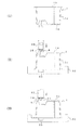
図1は、本発明の製造方法が対象とするインクカートリッジの一実施例を、シアン、マゼンタ、イエローの3種類のインクを収容するものについて示すものであって、図中符号1は、開口側が若干末広がりとなるほぼ直方体の容器本体で、各部材との接合を熱溶着により行いやすくするために、ポリプロピレン、ポリエチレン、ポリスチレン等の高分子材料を射出成形して構成されている。   FIG. 1 shows an embodiment of an ink cartridge targeted by the manufacturing method of the present invention, which contains three types of inks of cyan, magenta, and yellow. In FIG. The container body is a substantially rectangular parallelepiped that is slightly widened, and is made by injection molding a polymer material such as polypropylene, polyethylene, polystyrene, etc., in order to facilitate joining with each member by thermal welding.

容器本体1は、仕切り板2、3、4よりインクを吸収するのに適した弾性材料からなる多孔質体5を収容するフォーム室6、6、6と、インクをそのまま収容するインク室7、7、7に分離されている。   The container body 1 includes foam chambers 6, 6, 6 for storing a porous body 5 made of an elastic material suitable for absorbing ink from the partition plates 2, 3, 4, an ink chamber 7 for storing ink as it is, 7 and 7 are separated.

各フォーム室6の下端には記録ヘッドのインク供給針と係合するインク供給口8が設けられ、また容器本体1の開口は、フォーム室6のインク供給口8の近傍に位置するように穿設されたインク注入口9、9、9と、大気連通口10、10、10を備えた蓋体11で封止されている。   An ink supply port 8 that engages with an ink supply needle of the recording head is provided at the lower end of each foam chamber 6, and the opening of the container body 1 is drilled so as to be positioned in the vicinity of the ink supply port 8 of the foam chamber 6. It is sealed with a lid 11 having ink inlets 9, 9, 9 provided and air communication ports 10, 10, 10.

各フォーム室6の底部には、多孔質体5を蓋体11と協同して圧縮するための凸部12が形成されていて、その上端に一定の開口面積を有する空室を形成する凹部13が形成され、この凹部13からインク供給口8まで延びる通孔14が穿設されている。通孔14の外端には、記録ヘッドのインク供給針と液密に係合するように拡開部15を形成して、パッキン16が挿入されており、また凸部12の先端には凹部13を覆うようにフィルタ材17が貼着されている。   A convex portion 12 for compressing the porous body 5 in cooperation with the lid body 11 is formed at the bottom of each foam chamber 6, and a concave portion 13 that forms an empty chamber having a certain opening area at the upper end thereof. And a through hole 14 extending from the recess 13 to the ink supply port 8 is formed. An expanded portion 15 is formed at the outer end of the through-hole 14 so as to be liquid-tightly engaged with the ink supply needle of the recording head, and a packing 16 is inserted. The filter material 17 is stuck so that 13 may be covered.

これらフィルター材18、凹部12、及び通孔14のインクと接する面は、紫外線を照射してインクに対する濡れ性を改善する処理が施されている。   The surface of the filter material 18, the concave portion 12, and the through-hole 14 in contact with the ink is subjected to a treatment for improving the wettability with respect to the ink by irradiating ultraviolet rays.

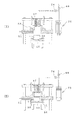
またパッキン16は、図3に示したように面16aにリング状の細いリブ16bを形成して構成されており、図4(イ)に示したように凸部12側の上面16aに耐インク性を備えた接着剤19を塗布して容器本体1との間の空間Sを完全に埋めるように装填されている。また同図(ロ)に示したようにインク供給針の挿通が可能な窓20aを備えた押圧部材20を、パッキン16の下端に弾接させて容器本体1に熱溶着され、パッキン16のリブ16bを拡開部15に弾性変形させた状態でパッキン16が挿入されている。   As shown in FIG. 3, the packing 16 is formed by forming thin ring-shaped ribs 16b on the surface 16a. As shown in FIG. 4 (a), the packing 16 has an ink resistant surface on the upper surface 16a. The adhesive 19 having the properties is applied so that the space S between the container body 1 and the container body 1 is completely filled. Further, as shown in FIG. 6B, the pressing member 20 having a window 20a through which the ink supply needle can be inserted is brought into elastic contact with the lower end of the packing 16 and thermally welded to the container body 1, and the rib of the packing 16 is The packing 16 is inserted in a state in which the expansion portion 15 is elastically deformed by 16b.

このような手法を採ることによりパッキン16の側部と拡開部15との間に存在する空間Sと通孔14との連通を断つことができる。   By adopting such a method, the communication between the space S existing between the side portion of the packing 16 and the expanded portion 15 and the through hole 14 can be cut off.

このようにパッキン16を挿入して形成されたインク供給口8の先端にはインク供給針の挿入により破損可能で、かつ好ましくは気体透過性が高く、水分透過性が低い低密度ポリエチレンフィルム等からなる遮気性フィルム21が貼着され、また容器本体1の底部1aとの間には肉盗み部22を設けて、包装袋等に密閉された場合にも内部に空間を確保できるように構成されている。   The tip of the ink supply port 8 formed by inserting the packing 16 in this way can be damaged by the insertion of the ink supply needle, and is preferably made of a low density polyethylene film having high gas permeability and low moisture permeability. An air-tight film 21 is attached, and a meat stealing portion 22 is provided between the bottom 1a of the container body 1 so that a space can be secured even when sealed by a packaging bag or the like. ing.

蓋体11の表面には、図5(イ)に示したように一端が大気連通口10に連通し、また他端が蓋体11の他側に延びる蛇行した溝23、23、23が形成され、図5(ロ)に示したようにインク注入口9、大気連通口10、及び溝23を覆うように、舌片24aの引き剥がしにより溝23の先端23aを大気に開放可能とするフィルム24が貼着されている。このフィルム24は、気体透過性が高く、水分透過性が低い低密度ポリエチレンフィルム等の遮気性フィルムを使用するのが望ましい。   On the surface of the lid body 11, meandering grooves 23, 23, 23 are formed with one end communicating with the atmosphere communication port 10 and the other end extending to the other side of the lid body 11 as shown in FIG. Then, as shown in FIG. 5B, the film 23 can be opened to the atmosphere by peeling off the tongue piece 24a so as to cover the ink injection port 9, the atmosphere communication port 10, and the groove 23. 24 is stuck. As this film 24, it is desirable to use an air-tight film such as a low-density polyethylene film having a high gas permeability and a low moisture permeability.

つぎに製造方法について説明する。
図6は、製造工程中、容器本体を移送するためのパレットの一実施例を示すものであって、パレット30は、その表面に容器本体1の底面1aの外周が填まり込む位置と、開口1bの内面が填まり込む位置のそれぞれ少なくとも4本ずつのピン31、及び32を植設し、またインク供給口8が対向する位置にはこれを収容できる凹部33を形成し、さらに周囲に後述するインク注入工程でシール部を形成する段差部34を形成して構成されている。
Next, the manufacturing method will be described.
FIG. 6 shows an embodiment of a pallet for transferring the container main body during the manufacturing process. The pallet 30 has a position where the outer periphery of the bottom surface 1a of the container main body 1 fits in the surface, and an opening. At least four pins 31 and 32 at positions where the inner surface of 1b is fitted are planted, and a recess 33 is formed at a position where the ink supply port 8 faces, and further, a recess 33 is formed around the pin. In this ink injection step, a step portion 34 is formed to form a seal portion.

先ず、予め射出成形により形成された容器本体1(図7(I))を底面1aが上方となるように開口部1bをピン31に位置合わせしてパレット30にセットし、先端に耐インク性を備えた接着剤を薄く塗布したパッキン16をインク供給口8に仮圧入し、次いで中心を軸にして押込み治具40を回動させて摩擦を低減させながら所定位置まで圧入する(図7(II))。このようにねじれを与えながら圧入すると、パッキン16は、周縁等の端部領域のめくれ上がりや、ねじれを起こすこと無くインク供給口8に嵌合されるため、装填後にパッキン16がインク供給口8からの飛び出しを確実に防止でき、また容器本体1との間のすき間を接着剤で埋めることができる。   First, the container body 1 (FIG. 7 (I)) formed in advance by injection molding is set on the pallet 30 with the opening 1b aligned with the pin 31 so that the bottom surface 1a faces upward, and ink-resistant at the tip. 7 is applied to the ink supply port 8 by temporary press-fitting, and then the push-in jig 40 is rotated about the center to reduce the friction and press-fitted to a predetermined position (FIG. 7 ( II)). When the press-fitting is performed while twisting in this way, the packing 16 is fitted into the ink supply port 8 without causing the end region such as the peripheral edge to be turned up or twisted. Can be reliably prevented, and the gap between the container body 1 can be filled with an adhesive.

またパッキン16をインクに浸漬してインクを付着させてから、上述と同様に装填し、前述したようにインク供給針の挿通が可能な窓20aを備えた押圧部材20を、パッキン16の下端に弾接させて容器本体1に熱溶着することにより、後述するインク充填工程でインクが進入し難い空間20(図4)に予めインクを注入して、パッキン16の外側側面と拡開部15との間の空間とインク供給口8とを遮断することができる。   In addition, after the packing 16 is immersed in the ink and the ink is attached, the packing member 16 is loaded in the same manner as described above, and the pressing member 20 having the window 20a through which the ink supply needle can be inserted is attached to the lower end of the packing 16 as described above. By insulatively contacting and thermally welding to the container main body 1, ink is injected in advance into the space 20 (FIG. 4) in which ink is difficult to enter in an ink filling process described later, and the outer side surface of the packing 16 and the expanding portion 15 And the ink supply port 8 can be blocked.

熱溶着性材料からなる遮気性フィルム21をインク供給口8を覆うようにセットし、治具41によりインク供給口8の周囲を加熱、加圧して、インク供給口8をフィルム21により封止し(図7(III))、必要に応じて底面1aや側面1cにロット番号や有効期限を印刷したり、刻印する。   An airtight film 21 made of a heat-welding material is set so as to cover the ink supply port 8, and the periphery of the ink supply port 8 is heated and pressurized by a jig 41, and the ink supply port 8 is sealed with the film 21. (FIG. 7 (III)), a lot number and an expiration date are printed or stamped on the bottom surface 1a and the side surface 1c as necessary.

容器本体1の底面1aに対する全ての作業が終了した段階で、容器本体1を天地返して容器本体1の開口部1bが上方となるように容器本体1をパレット30に再セットする。   At the stage when all the operations on the bottom surface 1a of the container body 1 are completed, the container body 1 is turned upside down and the container body 1 is reset on the pallet 30 so that the opening 1b of the container body 1 faces upward.

インク供給口8と通口により通する凸部12に形成されている凹部13の幅よりも若干大きめの幅を有するフィルタとなる不錆鋼のメッシュ材や不織布等のフィルター材のテープを、長手方向に対して斜め方向に所定のサイズに切断してフィルター材17を形成し、これを凹部13を覆うようにセットし、セット後に容器本体1が若干軟化する程度に治具42により加熱、加圧して熱溶着する(図8(I))。不錆鋼のワイヤを織ってフィルター材17のテープが構成されている場合には、縦糸及び横糸となるワイヤの方向に対して非平行となるように切断することにより、ほつれを防止することができる。   A tape of filter material such as non-rust steel mesh material or non-woven fabric, which becomes a filter having a width slightly larger than the width of the concave portion 13 formed in the convex portion 12 that passes through the ink supply port 8 and the through port, The filter material 17 is formed by cutting it into a predetermined size in an oblique direction with respect to the direction. The filter material 17 is set so as to cover the concave portion 13, and heated and heated by the jig 42 to such an extent that the container body 1 is slightly softened after setting. And heat-welded (FIG. 8 (I)). When the tape of the filter material 17 is formed by weaving a non-rust steel wire, it is possible to prevent fraying by cutting it so as to be non-parallel to the direction of the wire to be warp and weft. it can.

ほつれの発生を皆無とすると次のような効果がある。すなわち、フィルター材17を構成するワイヤがパッキン16の領域に浸入すると、カートリッジを記録ヘッドに装着する際に記録ヘッドのインク供給針とパッキン16との間にワイヤが挟まり込み、これに起因して記録ヘッドのインク供給針とカートリッジとの気密性の保持が低下して外部からの空気の浸入を許して記録ヘッドへのインクの供給に支障を来すという問題を生じるが、ほつれを無くするとこの問題を確実に回避することができる。   If no fraying occurs, the following effects are obtained. That is, when the wire constituting the filter material 17 enters the region of the packing 16, the wire is sandwiched between the ink supply needle of the recording head and the packing 16 when the cartridge is mounted on the recording head. The maintenance of the air tightness between the ink supply needle of the recording head and the cartridge is lowered, and the problem of causing the intrusion of air from the outside and hindering the ink supply to the recording head occurs. The problem can be avoided reliably.

また、フィルタ−材17が固定される凸部12の形状、通常円形、もしくは楕円形に一致わせてフィルター材をプレスで打ち抜き加工する整形方法に比較して、上述のようにテープ材を斜めカットする整形方法を採ると、ワイヤのほつれ防止の他にテープ材の有効利用を図ることができる。   Also, the tape material is cut obliquely as described above, compared to the shaping method in which the filter material is punched out by press so as to match the shape of the convex portion 12 to which the filter material 17 is fixed, usually circular or elliptical. If the shaping method is used, the tape material can be effectively used in addition to preventing fraying of the wire.

ついで、多孔質体5の圧入工程に移る。
図9(イ)(ロ)は、それぞれ多孔質材挿入装置、及び多孔質材挿入工程の一実施例を示すものであって、多孔質材挿入装置は、図9(イ)に示したように櫛歯状に形成されて、対向方向に移動可能な圧縮部材43、43と、これの間に位置して上下動可能な押圧部材44とから構成されている。
Next, the process proceeds to the press-fitting process of the porous body 5.
FIGS. 9 (a) and 9 (b) show examples of the porous material insertion device and the porous material insertion step, respectively, and the porous material insertion device is as shown in FIG. 9 (a). The compression members 43 are formed in a comb-like shape and are movable in the opposing direction, and the pressing member 44 is positioned between them and can be moved up and down.

圧縮部材43、43を水平方向に移動させて多孔質材5を挟み(図9(ロ)I)、圧縮部材43、43の外端の幅がフォーム室6の内幅よりも小さくなるまで圧縮部材43、43を押圧部材44側に移動させて多孔質材5をその幅がフォーム室6の幅よりも小さくなるように圧縮する(図9(ロ)II)。   The compression members 43 and 43 are moved in the horizontal direction to sandwich the porous material 5 (FIG. 9 (b) I), and compressed until the outer end width of the compression members 43 and 43 becomes smaller than the inner width of the foam chamber 6. The members 43 and 43 are moved to the pressing member 44 side, and the porous material 5 is compressed so that the width becomes smaller than the width of the foam chamber 6 (FIG. 9 (B) II).

ついでフォーム室6に移動して2本の圧縮部材43、43の間の押圧部材44を容器本体1側に移動させて多孔質材5を上端からフォーム室6に押込む(図9(ロ)III)。ついで押圧部材44を若干さらに降下させてから、容器1を多孔質挿入装置から待避させる。   Subsequently, it moves to the foam chamber 6, moves the pressing member 44 between the two compression members 43, 43 to the container body 1 side, and pushes the porous material 5 into the foam chamber 6 from the upper end (FIG. 9B). III). Next, after the pressing member 44 is slightly lowered, the container 1 is retracted from the porous insertion device.

これにより、図8(II)に示したようにフォーム室6の容積よりも若干大きく成形された多孔質材5が圧縮された状態でフォーム室6にセットされる。   As a result, as shown in FIG. 8 (II), the porous material 5 molded slightly larger than the volume of the foam chamber 6 is set in the foam chamber 6 in a compressed state.

ついで容器本体1の開口部1bに蓋材11を位置決めし、所定の圧力で蓋部材11を容器本体1に押圧しながら開口部1bを含む平面内で治具45を介して蓋材11の平面を含む方向、または垂直な方向、さらには斜め方向の何れか、または組み合わせた方向に超音波振動を加えて、容器本体1の開口部1bと蓋材11の裏面とを摩擦溶融させて接着する(図8(III))。   Next, the lid member 11 is positioned in the opening 1b of the container main body 1, and the plane of the lid 11 is inserted through the jig 45 in a plane including the opening 1b while pressing the lid member 11 against the container main body 1 with a predetermined pressure. Ultrasonic vibration is applied in a direction including the vertical direction, a vertical direction, or an oblique direction, or a combined direction, and the opening 1b of the container body 1 and the back surface of the lid member 11 are friction-melted and bonded. (FIG. 8 (III)).

溶着後、容器本体1、及び蓋材11を構成する材料を軟化させるに足る温度に加熱した加熱棒46を接合部の周囲に当接させたり、また噴射ノズル47から熱風を噴射して接合時により生じたバリ等を除去する(図10)。   After welding, a heating rod 46 heated to a temperature sufficient to soften the material constituting the container main body 1 and the lid member 11 is brought into contact with the periphery of the joining portion, or hot air is jetted from the jet nozzle 47 at the time of joining. The burr | flash etc. which arose by removing are removed (FIG. 10).

このようにして容器が完成した段階で、インク注入ステーションに移動する。
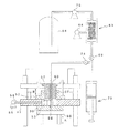
図11はインク注入装置の一実施例を示すものであって、図中符号50は、パレット30を保持する受台で、図示しない駆動機構により矢印Aで示すように上下動可能に構成されている。51は、基台で、貫通口を備え、下面をパレット30の周面の段差部34とにより、また上面を後述する蓋部材52とにより注入室53を形成し、また流路54により真空ポンプ55に接続されている。
When the container is completed in this way, it moves to the ink injection station.
FIG. 11 shows an embodiment of the ink injection device. Reference numeral 50 in the drawing is a pedestal for holding the pallet 30 and is configured to move up and down as indicated by an arrow A by a drive mechanism (not shown). Yes. Reference numeral 51 denotes a base, which has a through-hole. The lower surface is formed by a stepped portion 34 on the peripheral surface of the pallet 30 and the upper surface is formed by a lid member 52 which will be described later. 55.

52は、前述の蓋部材で、注入室53に対向する領域に通口56が穿設され、ここに気密状態を保持しながら図中矢印Bで示したように上下動可能なピストン部材57が挿入されている。   52 is a lid member as described above, and a through hole 56 is formed in a region facing the injection chamber 53, and a piston member 57 that can move up and down as shown by an arrow B in the figure while maintaining an airtight state is provided. Has been inserted.

ピストン部材57は、注入室53にセットされた容器1のインク注入口9に対向する位置に注入針58と、容器1の大気連通口10に対向するように図示しない給気装置に連通する流路60を設けて構成されている。また注入針58は、流路59、チューブ61を介して分岐管62に接続されている。   The piston member 57 is a flow communicating with an air supply device (not shown) so as to oppose the injection needle 58 and the air communication port 10 of the container 1 at a position facing the ink injection port 9 of the container 1 set in the injection chamber 53. A path 60 is provided. The injection needle 58 is connected to the branch pipe 62 via the flow path 59 and the tube 61.

63は、気液分離ユニットで、この実施例では中空糸束64を液流路とするように上端と下端をシリンダ65に液密に固定し、またシリンダ65を真空ポンプ66に接続して中空糸の外周に負圧を作用させるように構成され、シリンダ65の一端がチューブ67によりインクタンク68に接続され、また他端が止弁69を介して分岐管62に接続されている。   Reference numeral 63 denotes a gas-liquid separation unit. In this embodiment, the upper end and the lower end are liquid-tightly fixed to the cylinder 65 so that the hollow fiber bundle 64 is used as a liquid flow path, and the cylinder 65 is connected to a vacuum pump 66 to be hollow. The cylinder 65 is configured to apply a negative pressure to the outer periphery of the yarn. One end of the cylinder 65 is connected to the ink tank 68 by a tube 67 and the other end is connected to the branch pipe 62 via a stop valve 69.

70は、計量管で、シリンダ71とピストン72とにより構成され、上死点側がチューブ73により分岐管62に接続されている。なお、図中符号74は止弁を、また75はインク圧送用のポンプをそれぞれ示す。   Reference numeral 70 denotes a measuring tube, which includes a cylinder 71 and a piston 72, and the top dead center side is connected to the branch pipe 62 by a tube 73. In the figure, reference numeral 74 denotes a stop valve, and 75 denotes a pump for ink pressure feeding.

前述の工程により各部材の組み付けが終了した容器1を載せたパレット30がインク注入装置に到達して、注入室53の下方にセットされると(図12(I))、受台50が基台51の下面に密着するまで上昇する(図12(II))。   When the pallet 30 on which the container 1 in which the assembly of each member has been completed by the above-described process has reached the ink injection device and is set below the injection chamber 53 (FIG. 12 (I)), the cradle 50 is the base. It rises until it comes into close contact with the lower surface of the base 51 (FIG. 12 (II)).

ついでピストン56を容器1の蓋部材11との間に空間が確保できる程度まで降下させて、また気液分離ユニット63に連通する止弁68を閉弁状態に維持したまま止弁74を開弁して、真空ポンプ55を作動させて注入室53、チューブ61、73、及び計量管70を所定の圧力まで減圧する(図13(I))。   Next, the piston 56 is lowered to such an extent that a space can be ensured between the lid member 11 of the container 1 and the stop valve 74 is opened while the stop valve 68 communicating with the gas-liquid separation unit 63 is kept closed. Then, the vacuum pump 55 is operated to depressurize the injection chamber 53, the tubes 61 and 73, and the measuring tube 70 to a predetermined pressure (FIG. 13I).

所定の圧力まで減圧が進行した段階で、止弁74を閉弁し、また止弁68を開弁して所定量のインク7を計量管63に注入し(図13(II))、これに併行してピストン部材57を下死点まで降下させる。これによりピストン部材47の下端の各パッキン77、78が容器1のインク供給口10、及び大気連通口10に弾接し、また注入針58が容器1の底面近傍まで進入する。   When the pressure has been reduced to a predetermined pressure, the stop valve 74 is closed, and the stop valve 68 is opened to inject a predetermined amount of ink 7 into the metering pipe 63 (FIG. 13 (II)). At the same time, the piston member 57 is lowered to the bottom dead center. As a result, the packings 77 and 78 at the lower end of the piston member 47 are brought into elastic contact with the ink supply port 10 and the atmosphere communication port 10 of the container 1, and the injection needle 58 enters the vicinity of the bottom surface of the container 1.

この挿入過程においては、好ましくは注入針58がフィルタ17の直上に位置させると、フィルタ17、凹部13、通孔14、パッキン16に気泡を残留させることなくインクを確実に充填することができる。そして、インク注入針のインク噴出口を放射状に形成することにより、多孔質材5全体に均等にインクを吸収させることができる。   In this insertion process, preferably, when the injection needle 58 is positioned immediately above the filter 17, the ink can be reliably filled without leaving bubbles in the filter 17, the recess 13, the through hole 14, and the packing 16. Ink can be evenly absorbed by the entire porous material 5 by forming the ink ejection ports of the ink injection needles radially.

また計量管70に接近して気液分離ユニット63が接続されているため、計量管70には気液分離ユニット63で脱気された直後のインクが流入する。   Further, since the gas-liquid separation unit 63 is connected close to the measuring tube 70, the ink immediately after deaeration by the gas-liquid separating unit 63 flows into the measuring tube 70.

ついで、止弁69を閉弁して気液分離ユニット63と遮断した状態で、止弁74を開弁して計量管70のピストンを押圧して所定量のインクを排出すると、容器1には所定量のインクが注入される(図14))。   Next, when the stop valve 69 is closed and shut off from the gas-liquid separation unit 63, the stop valve 74 is opened and the piston of the metering tube 70 is pressed to discharge a predetermined amount of ink. A predetermined amount of ink is injected (FIG. 14)).

このとき、気液分離ユニット60により確実に脱気されたインクが多孔質体5に注入されるため、インクは、上述の減圧工程(図13(I))では排出しきれなかった多孔質体5の細孔内に吸着されている気体を容易に溶解させて多孔質材5内に気泡を発生させたりまた残留させること無く、多孔質体5に均一に吸収される。   At this time, since the ink reliably deaerated by the gas-liquid separation unit 60 is injected into the porous body 5, the ink cannot be completely discharged in the above-described decompression step (FIG. 13 (I)). The gas adsorbed in the pores 5 is easily dissolved, and bubbles are not generated in the porous material 5 or remain in the porous material 5 and are uniformly absorbed by the porous body 5.

特に止弁74とインク注入針58を接続するチューブ61を、インク注入期間中、室温よりも温度が10乃至20°C程度上昇するように加熱すると、インクの粘度が低下して多孔質体5の細孔に確実に進入させることができる。   In particular, when the tube 61 connecting the stop valve 74 and the ink injection needle 58 is heated so that the temperature rises by about 10 to 20 ° C. from the room temperature during the ink injection period, the viscosity of the ink decreases and the porous body 5 is reduced. It is possible to reliably enter the pores.

これにより、インクの注入が終了した時点では、少なくとも多孔質材5には気体が存在しなくなるため、気泡を含むことがなく、印字品質を保証することができる。   As a result, since gas does not exist at least in the porous material 5 at the time when the injection of ink is completed, it is possible to guarantee the print quality without containing bubbles.

インクの注入が終了した段階で、排気口60を大気に開放して多孔質材5の上部に残ったインクを大気圧との差圧により多孔質材5に完全に吸収させる。その後、受台50を降下させ、パレット40を次の工程に移動させてインク注入口9等に付着しているインクを真空吸引や布等で拭き取り、最後にインク注入口9に導管を当接させて微小な正圧を作用させて、蓋体11の裏に付着しているインクを多孔質体5側に拭き落とす。   When the ink injection is completed, the exhaust port 60 is opened to the atmosphere, and the ink remaining on the upper portion of the porous material 5 is completely absorbed by the porous material 5 due to the differential pressure from the atmospheric pressure. Thereafter, the cradle 50 is lowered, the pallet 40 is moved to the next process, and ink adhering to the ink inlet 9 and the like is wiped off by vacuum suction or cloth, and finally a conduit is brought into contact with the ink inlet 9. Then, a minute positive pressure is applied, and the ink adhering to the back of the lid 11 is wiped off to the porous body 5 side.

容器1を大気連通口10が上方となるように傾けて減圧容器に収容して、少なくとも大気連通口10、インク注入口9、及び細溝23を覆う程度のサイズに切断された遮気性フィルム24を治具80により熱溶着により仮止する(図15)。この際、温度上昇により容器1内の圧力が上昇したとしても、大気連通口10が可及的に上方に位置するから、膨張した空気は、大気連通口10から速やかに排出されてインク注入口9からのインクの漏洩を防止することができる。   The container 1 is tilted so that the atmosphere communication port 10 faces upward and accommodated in a decompression container, and the air-shielding film 24 cut to a size that covers at least the atmosphere communication port 10, the ink injection port 9, and the narrow groove 23. Is temporarily fixed by heat welding with a jig 80 (FIG. 15). At this time, even if the pressure in the container 1 rises due to the temperature rise, the atmosphere communication port 10 is positioned as high as possible. Therefore, the expanded air is quickly discharged from the atmosphere communication port 10 and the ink injection port. Ink leakage from 9 can be prevented.

次いで溝19を覆う領域を加熱してフイルム24の一半を溶着し、また他半の要部を引き剥がし可能な程度に溶着して、細溝19とフィルム24によりキャピラリを形成する。フィルム24の他半を貼着する以前にインクカートリッジを脱気室に収容して再脱気する場合には、その減圧値を200mmHg程度に抑えると、パッキン16により生じたフィルタ17よりもインク供給口近傍に残留する、気泡の発生核の物理的成長を抑えつつカートリッジを再減圧することができ、またインク注入口からのインクの噴出を抑え、インクカートリッジに可及的に多くのインクを充填することができる。   Next, the region covering the groove 19 is heated to weld one half of the film 24, and the other half is welded to such an extent that it can be peeled off, and a capillary is formed by the narrow groove 19 and the film 24. In the case where the ink cartridge is accommodated in the deaeration chamber before the other half of the film 24 is adhered, and the deaeration is suppressed to about 200 mmHg, the ink is supplied more than the filter 17 generated by the packing 16. The cartridge can be re-depressurized while suppressing the physical growth of bubble generation nuclei remaining in the vicinity of the mouth, and the ink cartridge is filled with as much ink as possible by suppressing the ejection of ink from the ink inlet. can do.

このようにして完成したインクカートリッジ70は、図16に示したようように少なくともインク供給口8のシール16を破損しないように少なくともインク供給口8に緩衝材81を当接させ、かつ遮気フィルム24の舌片24aを折り畳んだ上、遮気性フィルムにより構成された襠83a付きの袋83に挿入する。   As shown in FIG. 16, the completed ink cartridge 70 has at least a buffer material 81 in contact with the ink supply port 8 so as not to damage the seal 16 of the ink supply port 8, and an air shielding film. The 24 tongue pieces 24a are folded and inserted into a bag 83 with a bag 83a made of an airtight film.

そして開口部近傍の襠83aを内側に折り畳んで均等な厚みに成形した上で、減圧環境下で開口近傍を熱溶着して密封すると(図17(イ))、インク供給口8の近傍に設けられている肉盗み部22が袋83との間で減圧空間を形成する。一方、インク供給口8を封止するフィルム21をガス透過性が高く、かつ水分透過性が低い低密度ポリエチレンフィルム等により構成しておくと、インク供給口近傍のインクに溶存している空気だけがフィルム21を透過して肉盗み部22と袋83とで形成された減圧空間に排出される。これによりインク供給口近傍のインクの空気溶存度を可及的に低下させて記録ヘッドへの気泡の流入を防止することができる。   Then, the ridge 83a in the vicinity of the opening is folded inward to have a uniform thickness, and then the vicinity of the opening is thermally welded and sealed in a reduced pressure environment (FIG. 17 (a)), provided near the ink supply port 8. The meat stealing portion 22 formed forms a decompression space with the bag 83. On the other hand, if the film 21 for sealing the ink supply port 8 is made of a low density polyethylene film having high gas permeability and low moisture permeability, only air dissolved in the ink in the vicinity of the ink supply port. Passes through the film 21 and is discharged into the decompression space formed by the meat stealing portion 22 and the bag 83. As a result, the air solubility of the ink in the vicinity of the ink supply port can be reduced as much as possible to prevent bubbles from flowing into the recording head.

また、インク供給口8を封止するフィルム21、及び蓋体11のインク注入口9、排気口10、及び溝23を封止するフィルム24を気体透過性が高く、水分透過性が低い低密度ポリエチレンフィルム等の遮気性フィルムにより構成することにより、カートリッジのインク全体の溶存空気量を可及的に低減して、記録ヘッドでの気泡の発生を確実に防止することができる。
望ましくは、再脱気後、72時間以内に袋83に封入するのが望ましい。
In addition, the film 21 that seals the ink supply port 8, the ink injection port 9 of the lid 11, the exhaust port 10, and the film 24 that seals the groove 23 have high gas permeability and low moisture permeability. By using an air-shielding film such as a polyethylene film, the amount of dissolved air in the entire ink in the cartridge can be reduced as much as possible, and the generation of bubbles in the recording head can be reliably prevented.
Desirably, it is desirable to enclose the bag 83 within 72 hours after re-deaeration.

特に、記録ヘッドに初めてインクを充填する場合には、記録ヘッド内の気泡を確実にインクに溶解させて排除する必要上、カートリッジのインクをマイナス300mmHg程度の脱気度に維持しておくのが望まし。このようにインクに高い脱気度を維持させるためには容器の肉盗み部22の容積を大きくしたり、また袋83とカートリッジとの間に積極的にデッドスペースを形成する目的で、厚目の緩衝材81に凹部や通孔を設けたり、またスペーサを同封して封止するのが望ましい。   In particular, when the recording head is filled with ink for the first time, it is necessary to ensure that bubbles in the recording head are dissolved and eliminated in the ink, so that the ink in the cartridge is maintained at a degassing degree of about minus 300 mmHg. Desired. In order to maintain a high degree of deaeration in the ink in this way, the volume of the meat stealing portion 22 of the container is increased, or the dead space is positively formed between the bag 83 and the cartridge. It is desirable that the buffer material 81 be provided with a recess or a through hole, or that a spacer be enclosed and sealed.

最後にケース84に納めて商品に仕上げる(図17(ロ))。記録装置本体の付属品として同梱するインクカートリッジは、当該記録装置の記録ヘッドに最初に装着されるインクカートリッジであるから、前述した高い脱気度のインクを充填したものを選択し、また、サプライ用には脱気度が若干低いインクカートリッジを供給するのが望ましく、これら2種類のカートリッジを簡単に区別できるように、ケース84を記号や色で区別できるように構成しておく。   Finally, the product is put in a case 84 and finished into a product (FIG. 17B). Since the ink cartridge bundled as an accessory of the recording apparatus main body is an ink cartridge that is first mounted on the recording head of the recording apparatus, select one filled with the above-mentioned high deaeration ink, For supply, it is desirable to supply an ink cartridge having a slightly low degree of deaeration, and the case 84 is configured to be distinguishable by symbol or color so that the two types of cartridges can be easily distinguished.

なお、上述の実施例においてはインク室を備えたカートリッジに例を採って説明したが、図18に示したように容器1に多孔質材5を充填して、この多孔質材5にだけインクを収容するカートリッジ85の製造にも適用できることは明らかである。   In the above-described embodiment, the cartridge provided with the ink chamber has been described as an example. However, as shown in FIG. 18, the container 1 is filled with the porous material 5 and only the porous material 5 is filled with the ink. Obviously, the present invention can be applied to the manufacture of the cartridge 85 for storing the cartridge.

また、は図19に示したように小型のカートリッジ86にあってインク注入口と大気開放口とを兼用する1つの開口87だけが形成されているが、このような場合には、図20に示したようにインク注入針58と、排気装置に連通する流路60とを同軸に配置することにより、カートリッジ85の1つの開口87をインク注入作業と排気作業とに同時に利用することができる。   Further, as shown in FIG. 19, in the small cartridge 86, only one opening 87 which serves both as an ink injection port and an air release port is formed. In such a case, FIG. As shown, the ink injection needle 58 and the flow path 60 communicating with the exhaust device are arranged coaxially, so that one opening 87 of the cartridge 85 can be used simultaneously for the ink injection operation and the exhaust operation.

本発明の対象となるインクカートリッジの一実施例を示す組立斜視図である。1 is an assembled perspective view showing an embodiment of an ink cartridge that is a subject of the present invention. FIG. 図(イ)(ロ)は、それぞれ同上インクカートリッジの一実施例を示す断面図である。FIGS. 1A and 1B are cross-sectional views showing an embodiment of the ink cartridge. 図(イ)(ロ)は、それぞれパッキンに一実施例を示す上面図と断面図である。FIGS. 1A and 1B are a top view and a cross-sectional view showing an embodiment of the packing, respectively. 図(イ)(ロ)は、それぞれインク供給口の一実施例を拡大して示す断面図である。FIGS. 1A and 1B are enlarged sectional views showing one embodiment of the ink supply port. 図(イ)(ロ)は、それぞれインクカートリッジの蓋体の構造を、フィルムを取り去って示す図と、フィルムを貼着した状態で示す図である。FIGS. 1A and 1B are a diagram illustrating the structure of the lid of the ink cartridge with the film removed, and a diagram in which the film is attached. 容器を保持、搬送するパレットの一実施例を示す図である。It is a figure which shows one Example of the pallet which hold | maintains and conveys a container. 図(I)乃至(III)は、それぞれインクカートリッジ形成工程の内の初期の工程を示す図である。FIGS. (I) to (III) are diagrams showing initial steps of the ink cartridge forming step. 図(I)乃至(III)は、それぞれインクカートリッジ形成工程の内の中期の工程を示す図である。FIGS. (I) to (III) are diagrams showing intermediate stages of the ink cartridge forming process. 図(イ)は、多孔質材挿入装置の一実施例を、及び図(ロ)の(I)乃至(III)はそれぞれ多孔質材の容器本体への挿入工程を示す図である。FIG. 1 (a) is a view showing an embodiment of the porous material insertion device, and FIGS. 2 (I) to (III) are diagrams showing the steps of inserting the porous material into the container body. カートリッジの外形形状の整形工程を示す図である。It is a figure which shows the shaping process of the external shape of a cartridge. インク注入装置の一実施例を示す構成図である。It is a block diagram which shows one Example of an ink injection apparatus. 図(I)(II)は、それぞれインク注入工程の内の初期の工程を示す図である。FIGS. (I) and (II) are diagrams showing initial steps in the ink injection step. 図(I)(II)は、それぞれインク注入工程の内の中期の工程を示す図である。FIGS. (I) and (II) are diagrams showing intermediate stages of the ink injection process. インク注入工程の最後の工程を示す図である。It is a figure which shows the last process of an ink injection process. 遮気性フィルムの貼着工程を示す図である。It is a figure which shows the sticking process of an airtight film. 包装工程の内の前半の工程を示す図である。It is a figure which shows the process of the first half in a packaging process. 包装工程の内の後半の工程を示す図である。It is a figure which shows the process of the latter half in a packaging process. 本発明の製造方法が適用可能なインクカートリッジの他の実施例を示す図である。It is a figure which shows the other Example of the ink cartridge which can apply the manufacturing method of this invention. 本発明の製造方法が適用可能なインクカートリッジの他の実施例を示す図である。It is a figure which shows the other Example of the ink cartridge which can apply the manufacturing method of this invention. 同上インクカートリッジに適したインク注入装置の他の実施例を示す図である。It is a figure which shows the other Example of the ink injection apparatus suitable for an ink cartridge same as the above.

符号の説明Explanation of symbols

1 容器本体 5 多孔質体 6 フォーム室 7 インク室 8 インク供給口 9 インク注入口 10 大気連通口 11 蓋材 16 パッキン 16b リング状リブ 81 インクカートリッジ 83 袋     DESCRIPTION OF SYMBOLS 1 Container body 5 Porous body 6 Foam chamber 7 Ink chamber 8 Ink supply port 9 Ink inlet 10 Atmospheric communication port 11 Cover material 16 Packing 16b Ring-shaped rib 81 Ink cartridge 83 Bag

Claims (2)

インクを収容するインク収容領域、及び前記インク収容領域と連通するインク供給口を備えたインクカートリッジにおいて、前記インク供給口近傍のインクカートリッジ表面に凹部が形成されていて、前記インク供給口の開口部が、気体透過性が高く、水分透過性が低い低密度ポリエチレンフィルムにより封止され、また前記インク供給口近傍のインクカートリッジ表面の凹部により前記インクカートリッジとの間に空間を形成して減圧状態で遮気性フィルムにより包装されているインクカートリッジ。 An ink cartridge comprising an ink containing region for containing ink and an ink supply port communicating with the ink containing region, wherein a recess is formed on the surface of the ink cartridge near the ink supply port, and the opening of the ink supply port However, it is sealed with a low-density polyethylene film with high gas permeability and low moisture permeability, and a space is formed between the ink cartridge and the ink cartridge near the ink supply port to form a space under reduced pressure. An ink cartridge packaged with an airtight film. 前記空間が、前記インクカートリッジを構成する容器本体に設けられた肉盗み部により形成されている請求項1に記載のインクカートリッジ。   The ink cartridge according to claim 1, wherein the space is formed by a meat stealing portion provided in a container main body constituting the ink cartridge.
JP2003346866A 2003-10-06 2003-10-06 ink cartridge Expired - Lifetime JP4167961B2 (en)

Priority Applications (1)

Application Number Priority Date Filing Date Title
JP2003346866A JP4167961B2 (en) 2003-10-06 2003-10-06 ink cartridge

Applications Claiming Priority (1)

Application Number Priority Date Filing Date Title
JP2003346866A JP4167961B2 (en) 2003-10-06 2003-10-06 ink cartridge

Related Parent Applications (1)

Application Number Title Priority Date Filing Date
JP9076582A Division JPH10250104A (en) 1997-03-12 1997-03-12 Ink cartridge for ink-jet type recording apparatus, and its manufacture

Publications (2)

Publication Number Publication Date
JP2004009743A JP2004009743A (en) 2004-01-15
JP4167961B2 true JP4167961B2 (en) 2008-10-22

Family

ID=30439190

Family Applications (1)

Application Number Title Priority Date Filing Date
JP2003346866A Expired - Lifetime JP4167961B2 (en) 2003-10-06 2003-10-06 ink cartridge

Country Status (1)

Country Link
JP (1) JP4167961B2 (en)

Also Published As

Publication number Publication date
JP2004009743A (en) 2004-01-15

Similar Documents

Publication Publication Date Title
US7086723B2 (en) Ink cartridge for ink-jet recorder and method of manufacturing same
JPH10138507A (en) Manufacture of ink cartridge for ink jet recording unit
KR100497454B1 (en) Liquid container, liquid supplying apparatus, and recording apparatus
JP5804727B2 (en) Method and apparatus for manufacturing liquid storage container
JP2002321387A (en) Storage form of ink jet head and method for liquid filling during storage of ink jet head
JP4165278B2 (en) Ink jet recording apparatus and ink cartridge
JP4929798B2 (en) Liquid container, method for manufacturing the same, and ink jet recording apparatus using the liquid container
US6742879B2 (en) Dual chamber ink-jet cartridge
JP4167961B2 (en) ink cartridge
JP3596617B2 (en) Method for manufacturing ink cartridge
JP2003063031A (en) Method for manufacturing ink cartridge
JP3412150B2 (en) ink cartridge
JP2000158662A (en) Manufacture for ink cartridge for ink-jet recording apparatus
JP3666601B2 (en) Ink refilling method
JP2021151724A (en) Liquid supply device, liquid storage tank, cartridge and liquid discharge device
JP2001105618A (en) Ink cartridge, production method thereof and ink jet recording apparatus
JP3613346B2 (en) Ink cartridge filling method
JP2004314558A (en) Method and device for filling liquid in liquid containing bag
JP4213288B2 (en) Ink tank and manufacturing apparatus thereof
JP2004338146A (en) Method and device for filling liquid of liquid containing bag
JP4281372B2 (en) ink cartridge
JP2004122498A (en) Process for producing convex sheet being employed in liquid container, liquid container and its manufacturing process
JP2004050698A (en) Ink cartridge and its manufacturing method
JPH10329329A (en) Ink cartridge for ink jet recorder
JPH0958005A (en) Ink cartridge and manufacture thereof

Legal Events

Date Code Title Description
A131 Notification of reasons for refusal

Free format text: JAPANESE INTERMEDIATE CODE: A131

Effective date: 20031224

A131 Notification of reasons for refusal

Free format text: JAPANESE INTERMEDIATE CODE: A131

Effective date: 20040324

A02 Decision of refusal

Free format text: JAPANESE INTERMEDIATE CODE: A02

Effective date: 20040707

A521 Written amendment

Free format text: JAPANESE INTERMEDIATE CODE: A523

Effective date: 20040902

A911 Transfer of reconsideration by examiner before appeal (zenchi)

Free format text: JAPANESE INTERMEDIATE CODE: A911

Effective date: 20041025

A912 Removal of reconsideration by examiner before appeal (zenchi)

Free format text: JAPANESE INTERMEDIATE CODE: A912

Effective date: 20041217

RD04 Notification of resignation of power of attorney

Free format text: JAPANESE INTERMEDIATE CODE: A7424

Effective date: 20071221

RD03 Notification of appointment of power of attorney

Free format text: JAPANESE INTERMEDIATE CODE: A7423

Effective date: 20071227

A01 Written decision to grant a patent or to grant a registration (utility model)

Free format text: JAPANESE INTERMEDIATE CODE: A01

A61 First payment of annual fees (during grant procedure)

Free format text: JAPANESE INTERMEDIATE CODE: A61

Effective date: 20080804

R150 Certificate of patent or registration of utility model

Free format text: JAPANESE INTERMEDIATE CODE: R150

FPAY Renewal fee payment (event date is renewal date of database)

Free format text: PAYMENT UNTIL: 20110808

Year of fee payment: 3

FPAY Renewal fee payment (event date is renewal date of database)

Free format text: PAYMENT UNTIL: 20120808

Year of fee payment: 4

FPAY Renewal fee payment (event date is renewal date of database)

Free format text: PAYMENT UNTIL: 20130808

Year of fee payment: 5

S531 Written request for registration of change of domicile

Free format text: JAPANESE INTERMEDIATE CODE: R313531

R350 Written notification of registration of transfer

Free format text: JAPANESE INTERMEDIATE CODE: R350

EXPY Cancellation because of completion of term