JP4164471B2 - Liquid tank and liquid discharge recording apparatus equipped with the liquid tank - Google Patents
Liquid tank and liquid discharge recording apparatus equipped with the liquid tank Download PDFInfo
- Publication number
- JP4164471B2 JP4164471B2 JP2004162957A JP2004162957A JP4164471B2 JP 4164471 B2 JP4164471 B2 JP 4164471B2 JP 2004162957 A JP2004162957 A JP 2004162957A JP 2004162957 A JP2004162957 A JP 2004162957A JP 4164471 B2 JP4164471 B2 JP 4164471B2
- Authority
- JP
- Japan
- Prior art keywords
- ink
- liquid
- chamber
- introduction path
- absorber
- Prior art date
- Legal status (The legal status is an assumption and is not a legal conclusion. Google has not performed a legal analysis and makes no representation as to the accuracy of the status listed.)
- Expired - Fee Related
Links
Images


Classifications
-
- B—PERFORMING OPERATIONS; TRANSPORTING
- B41—PRINTING; LINING MACHINES; TYPEWRITERS; STAMPS
- B41J—TYPEWRITERS; SELECTIVE PRINTING MECHANISMS, i.e. MECHANISMS PRINTING OTHERWISE THAN FROM A FORME; CORRECTION OF TYPOGRAPHICAL ERRORS
- B41J2/00—Typewriters or selective printing mechanisms characterised by the printing or marking process for which they are designed
- B41J2/005—Typewriters or selective printing mechanisms characterised by the printing or marking process for which they are designed characterised by bringing liquid or particles selectively into contact with a printing material
- B41J2/01—Ink jet
- B41J2/17—Ink jet characterised by ink handling
- B41J2/175—Ink supply systems ; Circuit parts therefor
- B41J2/17503—Ink cartridges
- B41J2/17513—Inner structure
Description
本発明は、インクなどの液体(以下、単にインクと称する)を吐出して記録を行うインクジェット記録において、使用するインクを保持するインクタンク(液体タンク)、およびそれが搭載されるインクジェット記録装置(液体吐出機記録装置)に関する。 The present invention relates to an ink tank (liquid tank) that holds ink to be used in ink jet recording in which recording is performed by discharging a liquid such as ink (hereinafter simply referred to as ink), and an ink jet recording apparatus (see FIG. Liquid ejector recording apparatus).
従来、インクを直接保持するインク収容室と、インクを、内部に配置された吸収部材に吸収させて保持する吸収体室とを有し、両者が連通部を介して接続された構成のインクタンクが知られている。このようなインクタンクでは、吸収体室からインクが供給されるのに伴って、吸収体室に大気連通口を介して導入された空気が、連通部を介してインク収容室に導入されるとともに、インク収容室から吸収体室にインクが供給される、いわゆる気液交換動作によって、インク収容室から吸収体室に適宜インクが補充される。このような気液交換動作が安定して速やかに行われるようにし、それによって、インクタンク内の負圧を安定して制御し、記録ヘッドの吐出安定性を確保して高速記録を可能とする技術が特許文献1に提案されている。
2. Description of the Related Art Conventionally, an ink tank having an ink storage chamber that directly holds ink and an absorber chamber that absorbs and holds ink by an absorbing member disposed therein, and both are connected via a communication portion It has been known. In such an ink tank, as ink is supplied from the absorber chamber, air introduced into the absorber chamber via the atmosphere communication port is introduced into the ink storage chamber via the communication portion. The ink is appropriately replenished from the ink storage chamber to the absorber chamber by a so-called gas-liquid exchange operation in which ink is supplied from the ink storage chamber to the absorber chamber. This gas-liquid exchange operation is performed stably and promptly, thereby stably controlling the negative pressure in the ink tank, ensuring the ejection stability of the recording head, and enabling high-speed recording. A technique is proposed in
また、図17に特許文献2に示されたインクタンクの概略断面構成図を示す。このインクタンク51の内部には、インク56を直接保持するインク収容室57と、吸収部材54a,54bを収納する吸収体室55が形成されている。インク収容室57と吸収体室55は、両者を接続する連通部59を有する隔壁58によって仕切られている。
FIG. 17 is a schematic cross-sectional configuration diagram of the ink tank disclosed in
インク収容室57は、この連通部59を除いて密閉されている。一方、吸収体室55を形成する壁面には、インク消費に伴うインクタンク51内への大気の導入を行うための大気連通口52と、記録ヘッド部(不図示)へインクを供給するためのインク供給口53とが形成されている。インク供給口53は、中空の突出部の先端に形成され、この中空部内で、インク供給口53と吸収部材54bの間に圧接体62が配置されている。また、吸収体室55内には、大気連通口52の近傍に、リブ60によって吸収部材54が押さえられて、吸収部材54が存在しない空間(バッファ室61)が設けられている。
The
このインクタンク51では、インクタンク51の使用初期などには、吸収体室55におけるインク界面66は、図17に示すように、連通部59の上端より上に位置している。不図示の記録ヘッドによって吸収部材54内のインクが消費されると、インク界面66は下がっていく。そして、インク界面66が、図18に示すように、連通部59の上端である気液交換ポイント67に達すると、連通部59内のインクが吸収部材54の毛管力により引き込まれるとともに、引き込まれたインクの体積を補完するように、連通部59に大気が導入され、すなわち気液交換動作が行われる。この際、この気液交換動作によって、連通部59部分には、矢印FAで示す空気の流れと、矢印FIで示すインクの流れが生じる。
In the
このようにして、記録ヘッドによってインクが消費されてもその消費量に応じてインクが吸収部材54に補充され、吸収部材54は一定量のインクを保持した状態に保たれる(インク界面66が一定の高さの位置に維持さる)。それにより、吸収部材54によって、記録ヘッドに対して及ぼされる負圧がほぼ一定に保たれ、記録ヘッドは、良好なインク吐出が可能な状態に保たれる。
In this way, even if ink is consumed by the recording head, ink is replenished to the absorbing
また、図17,18に示す構成では、複数の吸収部材54a,54bを用いることによって、2つの吸収部材54a,54bの界面に液体を保持する作用を生じさせ、それによって、非使用時におけるインク収容室57への気体の導入を阻止することともに、気液交換動作の安定化が図られている。
In the configuration shown in FIGS. 17 and 18, by using a plurality of absorbing
このように、小型化が可能であり、かつインクの使用効率を高く維持することが可能なインクタンクは、本出願人により製品化され、現在も実用に供されている。 Thus, an ink tank that can be reduced in size and can maintain high ink use efficiency has been commercialized by the present applicant and is still in practical use.
また、特許文献3には、上述のインクタンクの吸収部材として、熱可塑性を有するオレフィン系樹脂からなる繊維を用いたインクタンクが提案されている。このインクタンクは、インクの貯蔵安定性に優れるとともに、インクタンクの筐体と繊維体材料とが同種の材料からなるためリサイクル性にも優れている。
また、特許文献4には、吸収部材内部の最も毛管力が低い部分のインク界面が低下した際に、気液交換を行うため、吸収体室からインク収容室へ気体を導入する溝をインクタンク底面に形成した構成が開示されている。
近年、インクジェット記録装置においては、記録速度の高速化が進み、それに伴って、インクタンクから記録ヘッドへ単位時間当たりに供給可能なインクの量を多くすることが求められている。インクタンクからのインク供給量が増加した場合、上述のようなインクタンクでは、インク収容室への空気の供給、あるいはインク収容室からのインクの補充が、インクタンクからのインク供給量に追いつかず、そのために、吸収体室内のインク界面が低下するのを回避する必要がある。すなわち、図19に示すように、吸収体室55内のインク界面が大きく低下してしまうと、インク収容室57内にインク56が残っているにもかかわらず、インク供給口53付近に十分なインクが存在する状態を保てず、インク供給が中断しまうことになりかねない。
In recent years, in an ink jet recording apparatus, the recording speed has been increased, and accordingly, it is required to increase the amount of ink that can be supplied from an ink tank to a recording head per unit time. When the ink supply amount from the ink tank increases, in the ink tank as described above, the air supply to the ink storage chamber or the ink replenishment from the ink storage chamber cannot catch up with the ink supply amount from the ink tank. Therefore, it is necessary to avoid a decrease in the ink interface in the absorber chamber. That is, as shown in FIG. 19, when the ink interface in the
また、記録速度の高速化や記録画像の高品位化のために、記録ヘッドに対しては、長尺化、インク吐出口の高密度化が進んできている。インクジェット方式の記録ヘッドでは、記録ヘッド内部にインクを充填する際、もしくは、記録動作を実行するに当たって、インク吐出口付近の増粘インクなどの除去によってインクの吐出性能を回復させるために、インク吐出口からインクを吸引する動作を行うことが知られており、記録ヘッドの長尺化、インク吐出口の高密度化が進むと、この吸引動作をより高い圧力で実行する必要が生じてくる。この際にも、やはり、吸収体室内のインク界面が低下するのを回避する必要がある。すなわち、吸引動作時にインク界面が低下してしまうと、インクタンク壁面と吸収部材の接触面においてメニスカスが崩壊して、記録ヘッド側に泡が巻き込まれてしまったり、メニスカス崩壊が起こらなかった場合でも、インク供給不良を起こしてしまったりすることになりかねない。 Further, in order to increase the recording speed and the quality of the recorded image, the recording head has been increased in length and the density of ink discharge ports has been increased. Ink jet recording heads use ink ejection to recover ink ejection performance by filling the recording head with ink or performing a recording operation by removing thickened ink near the ink ejection ports. It is known to perform an operation of sucking ink from the outlet. As the recording head becomes longer and the density of ink discharge ports increases, it becomes necessary to perform this suction operation at a higher pressure. Also in this case, it is necessary to avoid a decrease in the ink interface in the absorber chamber. That is, even if the ink interface is lowered during the suction operation, the meniscus collapses at the contact surface between the ink tank wall surface and the absorbing member, and bubbles are caught on the recording head side, or even when the meniscus collapse does not occur. Ink supply failure may occur.
このように、インクの供給量が多くなっても、吸収体室内でインク界面が低下するのを抑制する方策として、インク供給口と連通部の距離を短くし(流抵抗を低減することによって)、供給性を向上させることが考えられる。しかし、この方策では、インク収容室が吸収体室より上方にある状態で放置した場合などにおいて、インク漏れなどに対する信頼性の低下を招く恐れがある。また、吸収体密度を低下させ、流抵抗を低減することも考えられるが、この場合、吸収部材の、インクを保持する力が低下するため、やはり信頼性の低下を招く恐れがある。 As described above, as a measure for suppressing the drop of the ink interface in the absorber chamber even when the amount of ink supplied increases, the distance between the ink supply port and the communication portion is shortened (by reducing the flow resistance). It is conceivable to improve the supply ability. However, with this measure, there is a risk that reliability of ink leakage or the like may be lowered when the ink storage chamber is left in a state above the absorber chamber. In addition, it is conceivable to reduce the density of the absorber and reduce the flow resistance, but in this case, the force of the absorbing member that holds the ink is reduced, so that the reliability may also be lowered.
したがって、本発明の目的は、液体収容室と吸収体室とを有する液体タンクにおいて、液体収容の信頼性を低下させることなく、単位時間当たりに多くの液体を安定して供給可能な液体タンクを提供することにある。 Accordingly, an object of the present invention is to provide a liquid tank having a liquid storage chamber and an absorber chamber, which can stably supply a large amount of liquid per unit time without reducing the reliability of liquid storage. It is to provide.
上述の目的を達成するため、本発明の液体タンクは、液体吐出記録ヘッドに液体を供給するための液体供給口と、大気連通口と、液体を吸収して保持する吸収部材を収容している吸収体室と、該吸収体室に供給される液体を直接収容する液体収容室と、を有し、前記液体供給口には前記吸収部材よりも強い保持力を液体に及ぼす圧接体が前記吸収部材に接触して配置されており、吸収体室と液体収容室とは、両者を連通させる連通部が形成された隔壁によって仕切られ、液体収容室から連通部および連通部の吸収体室側上端を介して液体が補給されるものであって、 液体供給口が配されている側面には凹凸状に構成された経路を備えて構成された液体タンクにおいて、前記経路は、液体収容室内から前記吸収体室に渡って設けられており、前記経路の前記吸収体室側の端部の位置は、経路の圧接体側の端部(A)と該圧接体上面の前記経路側端部(B)との間に前記経路と前記圧接体とが直接連通しないために設けられた前記吸収体によって封止された封止領域を有する位置であることを特徴とする。 To achieve the above object, the liquid tank of the present invention is to accommodate a liquid supply port for supplying the liquid to the liquid body discharge recording head, the atmosphere communication port, the absorbing member for absorbing and retaining liquid an absorber chamber are having a liquid storage chamber for directly containing the liquid to be supplied to the absorber chamber, the pressure contact body to the liquid supply port on the strong retention force than the absorbent member in liquid the absorbing member is disposed in contact with, the absorbing material chamber and the liquid chamber is partitioned by a partition wall communicating portion for communicating the two persons has been formed, absorption of the communicating portion and communicating portions from the liquid accommodating chamber through the body chamber side upper end be one in which liquid is replenished, the liquid tank configured with a route that is configured uneven on the side of the liquid supply port is disposed, the path, from the liquid storage chamber is provided across the absorber chamber, before The position of the end of the absorber chamber side of the serial path, said pressure body and the path between the ends of the press body side of the path (A) and the path end of the piezoelectric Settai top and (B) It is a position which has the sealing area | region sealed with the said absorber provided in order not to communicate directly .
この構成によれば、液体タンクからの液体供給時、液体収容室内に連通部を介して空気が導入されるとともに行われる、液体収容室から吸収体室への液体の補充が、液体収容室から液体導入路を通って液体供給口側へ至るインクの流れによって行われるようにすることができる。 According to this configuration, when the liquid is supplied from the liquid tank, replenishment of the liquid from the liquid storage chamber to the absorber chamber, which is performed while air is introduced into the liquid storage chamber via the communication portion, is performed from the liquid storage chamber. It can be performed by the flow of ink that reaches the liquid supply port side through the liquid introduction path.
本発明によれば、液体タンクからの液体供給時、吸収体室に液体導入路を介して液体を補充することができ、それによって、液体収容室内における液体界面の、連通部の上端を大きく下回って低下するのを抑制することができる。したがって、本発明の液体タンクによれば、単位時間当たりに多くの液体を安定して供給可能である。この際、吸収体室内の吸収部材の液体保持力を弱めるなどする必要はないので、液体収容の信頼性を低下させることはない。 According to the present invention, when the liquid is supplied from the liquid tank, the absorber chamber can be replenished with the liquid via the liquid introduction path, thereby greatly lowering the upper end of the communication portion of the liquid interface in the liquid storage chamber. Can be suppressed. Therefore, according to the liquid tank of the present invention, a large amount of liquid can be stably supplied per unit time. At this time, since it is not necessary to weaken the liquid holding force of the absorbing member in the absorber chamber, the reliability of liquid storage is not reduced.
次に本発明の実施の形態について図面を参照して説明する。
(第1の実施形態)
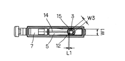
図1は、本発明の第1の実施形態のインクジェットカートリッジ、すなわちインクタンク1の構成を示す断面図である。
Next, embodiments of the present invention will be described with reference to the drawings.
(First embodiment)
FIG. 1 is a cross-sectional view illustrating a configuration of an ink jet cartridge, that is, an
本実施形態のインクタンク1は、インク6を直接収容するインク収容室(液体収容室)7と、インク6を吸収して保持する吸収部材4a,4bを圧縮状態で収容する吸収体室5を有している。吸収体室5に収容されている吸収部材4a,4bは、多数の毛細管が形成されているとみなすことができる構造を有しており、毛細管のメニスカス力、すなわち毛管力によって負圧を発生させてインク6を吸収、保持するものであり、負圧発生部材とも称される。
The
インク収容室7と吸収体室5は、隔壁8によって仕切られており、インクタンク1の下部で隔壁8に形成された連通部9を介してのみ連通している。インク収容室7は、連通部9を除いて実質的に密閉されている。一方、吸収体室5には、上部に、インクタンク1の外部に連通する大気連通口2が形成され、下部に、記録ヘッドにインク6を供給するためのインク供給口(液体供給口)3が形成されている。インク供給口3は、底面から突出した部分の先端に形成されており、インク供給口3と吸収部材4bの底面との間には、吸収部材4a,4bよりも毛管力、すなわちインク6の保持力の強い圧接体12が配置されている。
The
また、インクタンク1の上壁の、吸収体室5側の部分には、内部に突出する形態で複数のリブ10が一体に成形されており、吸収部材4aの上面に当接している。それによって、上壁と吸収部材4aの上面との間にバッファ室11が確保されている。
Further, a plurality of
吸収部材4a,4bの材質としては、発泡ポリウレタンなどの多孔質体や繊維材料など、多数の毛細管を形成していると見なすことができる構造を形成可能な様々な部材を用いることができる。繊維材料を用いた構成では、ウレタンなどの多孔質体などを用いる場合に比べ、材料の選択自由度が大きいので、インク接液性により優れた材料を選択することができ、インクの接液安定性に優れたインクタンク1を提供できる。また、繊維材料に熱可塑性の樹脂やインクタンク1本体と同材質の材料を選択することによって、リサイクル性にも優れたインクタンクを提供できる。この他、繊維材料に芯鞘構成の繊維材料を選択することによって、繊維同士の交点を確実に固定できるので、インク保持力(毛管力)を安定して発生可能とし、インク保持特性すなわち、負圧特性の安定したインクタンク1を提供することができる。
As the material of the absorbing
本実施形態では、吸収部材4a,4bとして、芯部がポリプロピレン、鞘部がポリエチレンからなるオレフィン系樹脂からなる繊維材料を熱成形したものを使用している。この構成では、ポリプロピレンとポリエチレンの融点の違いを利用し、熱成形する時の温度を、融点の低い材料の融点と融点の高い材料の融点との間に設定する(例えばポリエチレンの融点より高く、ポリプロピレンの融点より低く設定する)ことによって、融点の低い繊維材料を接着剤として機能させることができる。それによって、繊維同士の交点を、鞘部を構成する、相対的に融点の低いポリエチレンを溶融させて容易に固定することができ、上述のように優れた特性のインクタンク1を実現している。
In the present embodiment, as the absorbing
本実施形態においては、特許文献2に開示された構成と同様に、吸収部材を毛管力の異なる4a,4bの2部材から構成し、上方に4a、下方に4bが位置するように積層して配置している。2つの吸収部材4a,4b間の界面13は、連通部9より高い位置になっている。
In the present embodiment, similarly to the configuration disclosed in
また、図1(b)に示すように、吸収体室5は、インク供給口3側の幅W2が、連通部9側の幅W1よりも狭い構成になっている。これによって、インク供給口3近傍で吸収部材4bを相対的に強く圧縮し、この部分の毛管力を連通部9側よりも強くして、インク供給口3近傍にインクがスムーズに供給されるようにしている。
As shown in FIG. 1B, the
また、本実施形態においては、インクタンク1の底部に、インク収容室7の底面から、連通部9の底面を通り、吸収体室5の底面に向かって連続して延びる実質的に矩形の溝としてインク導入路(液体導入路)14が形成されている。このインク導入路14によって、吸収部材4b内よりも低い流抵抗で、インク6をインク収容室7からインク供給口3側に導入可能である。
In the present embodiment, a substantially rectangular groove extending continuously from the bottom surface of the
この際、インク導入路14の、吸収体室5側の端部Aは、インク供給口3に通じる圧接体12の所までは達しておらず、インク収容室7からインク導入路14を介して直接、圧接体12にインク6が導かれることがないようになっている。すなわち、インク導入路14の端部Aと、圧接体12上面の、インク導入路14側の縁部Bとの間には、吸収部材4bと吸収体室5の内壁とが密着し、それによって、インク6が直接的にインク供給口3側に導かれるのを防止する働きをする封止領域15が形成されている。
At this time, the end A on the
そして、封止領域15の距離、すなわち圧接体12の端部Bとインク導入路14の端部Aとの距離L1は、連通部9の、吸収体室5側における上端Cを通る水平面と、圧接体12の上面との距離L2より短く構成されている。言い換えれば、吸収体室5内のインク界面16が、連通部9の上端の位置にある状態で、インク界面16付近に存在しているインク6が圧接体12によって引かれる際の流抵抗よりも、インク導入路14の端部A付近に存在するインク6が圧接体12によって引かれる際の流抵抗の方が小さくなるように設定されている。
The distance L1 between the sealing
ここで、L1,L2によって示す距離は、上述のような流抵抗の関係を満たすように設定しているものであり、厳密には、インクタンク1内部のインク6がインク供給口3を介して記録ヘッドへ供給される際、圧接体12の、内部にインク流束が実質的に発生する領域と、それぞれ、インク導入路14の端部A、インク界面16の、安定した時の位置との距離とすべきものである。したがって、距離L1,L2を設定する際の、圧接体12側の基準点は、厳密には、吸収部材4bと圧接体12の構成や記録ヘッドとの接続構成などによって影響されるが、実用的には、上述のように設定することができる。
Here, the distances indicated by L1 and L2 are set so as to satisfy the relationship of flow resistance as described above. Strictly speaking, the
図2は、本実施形態のインクタンク1が搭載される一例のインクジェット記録装置20の要部を示す模式的平面図である。このインクジェット記録装置20は、ガイドレール27に沿って往復移動可能に支持され、キャリッジモータ30によって駆動ベルト29を介して駆動されるキャリッジ21を有している。キャリッジ21には、例えば、ブラック(K)、シアン(C)、マゼンタ(M)、イエロー(Y)のインクをそれぞれ吐出するために4つのインクジェット記録ヘッド(液体吐出記録ヘッド)22が搭載され、インクタンク1としては、各インクを保持するものが、各インクジェット記録ヘッド22にそれぞれ接続されるように、キャリッジ21に着脱自在に搭載されている。また、インクジェット記録装置20は、往復移動するキャリッジ21上のインクジェット記録ヘッド22のインク吐出面に対向する位置を通るように被記録媒体24を搬送する、搬送モータ26によって駆動される搬送ローラ25などを含む搬送機構を有している。搬送モータ26とキャリッジモータ30は不図示の制御部に接続され、また、各インクジェット記録ヘッド22も、フレキシブルケーブル23を介して制御部に接続されており、制御部によって動作制御される。
FIG. 2 is a schematic plan view showing a main part of an example of the ink
インクジェット記録装置20による記録動作は、記録媒体24を所定の位置まで搬送した後、キャリッジ21を往復移動させつつ、インクジェット記録ヘッド22を駆動して、記録画像に応じて選択的にインクを吐出させる主走査を行い、その後、所定量ずつの搬送と主走査を繰り返すことによって実行される。
In the recording operation by the ink
また、インクジェット記録装置20には、キャリッジ21の移動経路の一端において、インクジェット記録ヘッド22に対向する位置に回復ユニット32が設けられている。回復ユニット32は、インクジェット記録ヘッド22のインク吐出面を覆い、インク吐出口からのインク吸引を行うためのキャップ31などを有している。このキャップ31は、インクタンク1装着時の、インクジェット記録ヘッド22へのインク充填や、記録動作時の回復動作に利用される。
Further, the
次に、図3,4を用いて、インクタンク1内部のインクが使用されていく際の動作について説明する。
Next, the operation when the ink in the
図3(a)は、ユーザーが使用する前のインクタンク1の内部を示している。通常、インクタンク1の使用開始前には、吸収部材4a,4b中に充分なインク6が含浸しており、吸収体室5内におけるインク界面16は、上方の吸収部材4a内に存在している。この状態では、吸収部材4a,4bの状態を毛細管にインク6が充填されたものと見なした時の、
みなし毛細管の水頭高さは充分高いところに位置している。
FIG. 3A shows the inside of the
The head of the deemed capillary is located high enough.
記録を行うと、記録ヘッドにおいてインクが消費され、インクタンク1内のインク6がインク供給口3を介して記録ヘッドに供給される。それによって、吸収体室5内の圧力が低下し、みなし毛細管の水頭高さも低下する。すなわち、インク消費に従って、図3(b)に示すように、吸収部材4a内のインク界面16が低下する。
When recording is performed, ink is consumed in the recording head, and
吸収体室5内部のインク6がさらに使用されると、インク界面16はさらに低下していくが、この際、吸収部材が毛管力の異なる4a,4bの2部材にて構成されていることによって、インク界面16が、下方の吸収部材4b内で低下する前に、上方の吸収部材4a内部のインクが使い切られる、それによって、インク界面16は、図3(c)に示すように、吸収部材4a,4b間の界面13と一旦等しくなり、すなわち、一部で大きく低下することなく、水平な状態に揃えられる。
When the
吸収体室5内部のインク6がさらに使用されると、今度は、下方の吸収部材4b内のインクが消費され、インク界面16は、図4(d)に示すように、吸収部材4b内に移動して、低下していく。
When the
吸収体室5内部のインクがさらに使用されると、やがて、図4(e)に示すように、インク界面16が連通部9の、吸収体室5側における上端である気液交換ポイント17に達する。すると、気液交換ポイント17においてメニスカスが破れ、吸収部材4の負圧によってインク収容室7のインク6が吸収部材4b内に引き込まれる(FI2)とともに、それによって、実質的に密閉空間となっているインク収容室7内が減圧状態となるため、大気連通口2を介して吸収体室5内に導入されている大気が連通部9を介してインク収容室7へ導入される(FA1)。
When the ink inside the
図4(f)はインク供給量がさらに多くなった場合のインク供給状態を示した物であり、供給量が増える為、気液交換ポイント17のみでの気液交換が追いつかなくなり、吸収部材4bのインク界面16が低下し、流抵抗の低いインク導入路14のインクが引き込まれる。これにより、実質的に密閉空間となっているインク収容室7内が減圧状態となるため、大気連通口2を介して吸収体室5内に導入されている大気が連通部9を介してインク収容室7へ導入される。この際、供給量は図4(e)より多い為、インク収容室7の圧力はより低くなり、気液交換ポイント17でのインク供給スピードより、気体導入スピードが速くなり、気液交換ポイントは吸収部材4b、4aおよび大気連通口2を介して大気に開放された状態が維持され、インク導入路14で供給したインク量を補完する分の大気の導入が可能となる。
FIG. 4F shows an ink supply state when the ink supply amount is further increased. Since the supply amount increases, the gas-liquid exchange at the gas-
このため、インク界面16付近のインク6が圧接体12側に移動し、すなわちインク界面16がさらに低下するのよりも優先的に、インク導入路14側のインク6が圧接体12側に移動する動作が行われる。すなわち、この状態では、インク6の流れは、図4(f)に示すように、インク導入路14を介して圧接体12に向かうものが支配的となり、それによって、インク界面16の低下が抑制される。
For this reason, the
その後、インクタンク1から記録ヘッドへのインク供給が終了すると、インク導入路14からのインク供給が終了する。そして、インク収容室7と吸収体室5の圧力差を等しくする分のインクがインク収容室7から吸収体室5に供給され、インク界面16が、連通部9の上端以上の高さになった時点で気液交換動作が終了する。この際のインク6の流れは、図4(g)に示すように、気液交換ポイント17部分での流れが支配的である。
Thereafter, when the ink supply from the
ここで、インク導入路14の、好ましい構成について、より詳細に説明する。まず、距離L1,L2の設定について、図5を参照して説明する。
Here, a preferable configuration of the
図5において、A領域は、L1>L2の関係となる領域であり、L1,L2がこの領域に入る設定であると、インク供給が継続して行われている際に、インク界面16付近のインクが圧接体12側に向かうインク6の流れの方が、インク導入路14を介してのインク6の流れよりも優勢になりがちである。本発明者らの検討によれば、L2≒12mm、L1≒13mmとした、図5に△で示す設定では、インクタンク1からのインクの導出量を増していった時に、インク界面16の低下が見られがちであった。また、L2が同様のインクタンク1において、L1≒18mmとした、図5に×で示す設定では、インク界面16の低下がさらに顕著に見られ、インクの導出量を増していくと、記録ヘッド内部に気泡を巻き込んでしまうのが確認された。これらの結果は、インクの導出量を相当に多くした場合に、このような傾向が現れるということであり、L1,L2の設定を領域A内に設定しても、インク界面16の低下を抑制する一定の効果は得られるが、L1,L2の設定は、領域Aを避けた方がより好ましい。
In FIG. 5, the area A is an area having a relationship of L1> L2, and when L1 and L2 are set to enter this area, when the ink supply is continuously performed, the area near the
また、本実施形態の構成では、インク供給性を向上させるために、インクタンク1を記録ヘッドに接続した際に、圧接体12が摺動し、吸収部材4bの底面を圧縮する構成としており、それによって、吸収部材4bの、圧接体12近傍部分での毛管力を高め、この部分にインク6を効率的に導くことができるようにしている。この際、圧接体12の摺動により吸収部材4bが持ち上げられ、インクタンク1の底面と吸収部材4bの底面との間に、圧接体12の周囲で多少の空間が形成される場合がある。そこで、インク収容室7と圧接体12が直接的に連通するのを防止するために、封止領域15にはある程度の幅が必要である。図5には、封止領域15に、このように十分な幅を確保するのが困難な領域をB領域として示しており、L1,L2の設定は、このB領域を避けて行うのが好ましい。なお、B領域は、インクタンク1の具体的な構成に合わせて変化するものであり、例えば圧接体12を摺動させないような構成で有れば、B領域を狭めることが可能となる。
In the configuration of the present embodiment, in order to improve the ink supply performance, when the
本実施形態においては、L1,L2はA領域、B領域に入らない設定とし、特に、L2≒12mmであることから、吸収部材4内部のインク界面16の低下マージン分を含め、L1≒5mmとした。
In the present embodiment, L1 and L2 are set so as not to enter the A area and the B area, and particularly L2≈12 mm. Therefore, L1≈5 mm including the margin of the
また、インク導入路14は、泡が大きな割合を占めると、圧接体12との間の流抵抗が上昇するため、泡の割合がより少なくなるようにするのが望ましい。そこで、インク導入路の断面形状については、試行した結果、幅を1.0mm程度とすると、インク導入路14内部の残留気泡のために、実効的にL1<L2の関係が満たされなくなってしまう場合があり、幅を1.8mm、深さを0.7mmとした。このような寸法は、インクタンク1の具体的な形態に合わせて適宜設定することが望ましい。
In addition, if the bubble occupies a large proportion of the
以上説明した本実施形態によれば、インク供給時に、インク供給口3側、すなわち圧接体12側にインク導入路14を介してインク6が流れることによって、インク界面16が、連通部9の上端を大きく下回って低下するのを抑制できる。それによって、単位時間当たりに多くのインクを安定して供給することが可能となる。この際、本実施形態の構成では、インクタンク1内に所定の溝によって構成されるインク導入路14を設けることによって、安定した、大容量のインク供給を可能とすることができるので、吸収部材4a,4bの保持能力を低下させるなどする必要はなく、インク漏れなどに対する信頼性を低下させることもない。また、インクタンク1の外形に影響を与えることもないので、既存のインクタンクと同一の外形を有し、したがって既存のインクタンクの代わりに使用することが可能でありながら、より大容量の、安定したインク供給を可能なインクタンクを提供することが可能である。
According to the present embodiment described above, when the ink is supplied, the
なお、本実施形態は、本発明を例示するものであり、本発明の範囲内で種々の変形が可能である。例えば、図6は、特許文献2におけるように、連通部9部分に、吸収体室5側において、上方に延びる溝9aが形成された構造のインクタンク1に、本実施形態におけるインク導入路14を設けた構成を示している、この場合、L2は、圧接体12と、溝9aの上端を通る水平面の距離となり、上述のようにL1<L2の関係を満たすようにするのが好ましい。このインクタンク1においても、インク導入路14を設けることによって、インク供給時に、インク界面16が、溝9aの上端を大きく下回って低下するのを抑制し、大容量の、安定したインク供給を可能とすることができる。
Note that this embodiment exemplifies the present invention, and various modifications are possible within the scope of the present invention. For example, as shown in FIG. 6, the
また、本実施形態においては、吸収部材4の底面とインクタンク1内壁との間の部分、すなわち、インクタンク1の底壁にインク導入路14を形成した構成を示したが、吸収部材4の側面とインクタンク1内壁との間に,すなわちインクタンク1の側壁にインク導入路14を形成してもよい。
(第2の実施形態)
次に、本発明の第2の実施形態について図7を用いて説明する。図7は、本実施形態のインクタンク1の、リブ10と吸収部材4bが当接する面の断面図であり、同図において第1の実施形態と同様の部分には同一の符号を付している。
Further, in the present embodiment, the configuration in which the
(Second Embodiment)
Next, a second embodiment of the present invention will be described with reference to FIG. FIG. 7 is a cross-sectional view of the surface of the
本実施形態では、インク供給口3の径W3が、インクタンク1の、インク供給口3部分での幅W4よりも十分に小さくなっている。そこで、インク導入溝14は、インク供給口3の外周全域に、周囲を取り囲むように延びており、このようにしても、圧接体12の縁とインク導入溝14との距離L1を十分にとり、インクがインク導入溝14から直接的に圧接体12に導入されて、インクタンク1のインク収容の信頼性が低下するのを防ぐのに十分な封止領域15を確保することが可能になっている。
In the present embodiment, the diameter W3 of the
本実施形態によれば、インク導入路14から圧接体12に、圧接体12の外周全域からインクを導入することが可能となり、インク供給が継続して行われている際に、圧接体12側に効率的にインクを補充することができる。
(第3の実施形態)
次に、第3の実施形態について図8を用いて説明する。図8は、本実施形態のインクタンク1の、リブ10と吸収部材4bが当接する面の断面図であり、同図において第1の実施形態と同様の部分には同一の符号を付している。
According to this embodiment, it is possible to introduce ink from the entire area of the outer periphery of the
(Third embodiment)
Next, a third embodiment will be described with reference to FIG. FIG. 8 is a cross-sectional view of the surface of the
本実施形態のインクタンク1は、複数、図に示す例では2つのインク導入路14を有している。複数のインク導入路14を設けることによって、各インク導入路14の幅を比較的狭くしても、インク導入路14を通るインクの流れの容量を十分に高くすることができる。そして、インク導入路14の幅を比較的狭くすることによって、インク導入路14内部に吸収部材の底面が押し出されて実質的な断面積が狭くなるのを低減し、インク導入路14の、有効にインクが流れる断面積を広くとって、インク供給性を良好にすることができる。
The
なお、本実施形態では、インク導入路14を2つとしたが、インク導入路14の数は、吸収体室5の大きさ、形状などに合わせて適宜設定することができる。
(第4の実施形態)
次に、第4の実施形態について図9を用いて説明する。図9は、本実施形態のインクタンク1の、リブ10と吸収部材4bが当接する面の断面図であり、同図において第1の実施形態と同様の部分には同一の符号を付している。
In the present embodiment, the number of the
(Fourth embodiment)
Next, a fourth embodiment will be described with reference to FIG. FIG. 9 is a cross-sectional view of the surface of the
本実施形態では、インク導入路14が、吸収体室5内に所定量だけ入り込むまでは1本になっており、そこから複数本、図に示す例では2本に分岐している。インク導入路14を2本に分岐させることによって、分岐した部分では、第3の実施形態と同様に、インク導入路14内部に吸収部材の底面が押し出されるのを低減し、インク導入路14の、有効にインクが流れる断面積を広くとって、インク供給性を良好にすることができる。
In the present embodiment, the number of the
一方、インク収容室7から吸収体室5内に所定量だけ入り込むまでの部分で、インク導入路14を1本とすることによって、幅の比較的狭いインクタンク1であっても、吸収体室5の側面とインク導入路14の距離W5を比較的大きく確保することができる。前述のように、吸収体室5は、連通部9側で幅が比較的広くなっており、それによって、この部分では、吸収部材と吸収体室5の側壁との当接力が比較的弱くなっている。そこで、このように吸収部材と吸収体室5の側壁との当接力が比較的弱くなっている部分において、インク導入路14の、側壁からの距離W5を広く確保することによって、大気連通口から吸収体室5に導入された空気が、吸収部材と吸収体室5の壁面との当接面を通ってインク導入路14に浸入するのを低減することができる。
(第5の実施形態)
次に、第5の実施形態について図10を用いて説明する。図10は、本実施形態のインクタンク1の、鉛直面に沿った断面図であり、同図において第1の実施形態と同様の部分には同一の符号を付している。
On the other hand, even if the
(Fifth embodiment)
Next, a fifth embodiment will be described with reference to FIG. FIG. 10 is a cross-sectional view along the vertical plane of the
本実施形態では、インク導入路14の深さが、吸収体室5側に向かうにつれて深くなっている。インク供給時、インク導入路14から吸収部材4bへのインク補充は、インク導入路14の、圧接体12側の部分におけるほど行われやすい。本実施形態の構成では、このようにインク補充が行われやすい部分で、インク導入路14を深くし、したがって容量を大きくすることによって、インク導入路14から吸収部材4bへのインク補充が効率的に行われるようにして、インク界面の低下を低減する作用を高めることができる。また、インク導入路14を深くすることによって、深くなった部分が、インク導入路14内部に浸入した空気によって形成された気泡を溜めるバッファ空間として働き、気泡のためにインク導入路14を通るインクの流れが妨げられるなどするのを低減することができる。
(第6の実施形態)
次に、第6の実施形態について図11を用いて説明する。図11は、本実施形態のインクタンク1の、鉛直面に沿った断面図であり、同図において第1の実施形態と同様の部分には同一の符号を付している。
In the present embodiment, the depth of the
(Sixth embodiment)
Next, a sixth embodiment will be described with reference to FIG. FIG. 11 is a cross-sectional view along the vertical plane of the
本実施形態では、インク導入路14の底面が、インク収容室7側に向かうにつれて低くなっており、したがって、インク導入路14の深さが、インク収容室7側に向かうにつれて深くなっている。この構成によれば、インク導入路14内部に形成された気泡が、インク導入路14の、圧接体12側の先端に浸入するのを低減することができ、この部分に常にインクが存在するようにして、この部分からの吸収部材4bへのインク補充が確実に行われるようにすることができる。また、この構成には、インク導入路14内に形成された気泡が、インク収容室7側に抜けやすくし、インク導入路14内に気泡が残留してインクの流れが妨げられるのを低減する作用もある。気泡がインク収容室7側に抜けやすくするために、吸収部材4bの底面を、インク収容室7側に向かって高くなるように形成してもよい。
(第7の実施形態)
次に、第7の実施形態について説明する。
In the present embodiment, the bottom surface of the
(Seventh embodiment)
Next, a seventh embodiment will be described.
本実施形態では、インクタンク1の、インク導入路14を形成する部分とそれ以外の部分とで表面張力を変化させる。すなわち、インク導入路14を形成する部分の表面に表面処理、例えば、親水化処理を施す。それによって、インク導入路14へのインク充填性を向上させることができる。なお、表面処理方法としては、インク導入路14部分と他の部分の表面張力を変化させるものであればよく、親水化処理に限られることはない。
(第8の実施形態)
次に、第8の実施形態について図12を用いて説明する。図12は、本実施形態のインクタンク1の、鉛直面に沿った断面図であり、同図において第1の実施形態と同様の部分には同一の符号を付している。
In the present embodiment, the surface tension is changed between the portion of the
(Eighth embodiment)
Next, an eighth embodiment will be described with reference to FIG. FIG. 12 is a cross-sectional view of the
本実施形態では、インク導入路14をインクタンク1本体の構成部材とは別部材のインク導入路構成部材19を用いて形成している。インク導入路構成部材19は、インクタンク1本体の底面に結合されており、インク導入路構成部材19を結合することによって形成されたインク導入路14は、その一端が、開口部19aを介してインク収容室7内に連通し、他端が、開口部19bを介して吸収体室7内に連通している。
In this embodiment, the
この構成によれば、インク導入路構成部材18の材質を、インクタンク1本体のものと変えることによって、比較的容易に、インク導入路14部分での表面張力を他の部分と変化させることができ、それによって、第7の実施形態において説明したように、インク導入路14へのインク充填性を向上させることができる。また、本実施形態の構成では、インク導入路14の、吸収部材4bの下方に位置する部分において、上面が、開口部19を除いてインク導入路構成部材19またはインクタンク1の構成部材によって覆われており、それによって、吸収部材4bがインク導入路14内部に落ち込んで、インク導入路14の実効的な断面積が低下するのを低減することができる。
(第9の実施形態)
次に、第9の実施形態について図13を用いて説明する。図13は、本実施形態のインクタンク1の、鉛直面に沿った断面図であり、同図において第1の実施形態と同様の部分には同一の符号を付している。
According to this configuration, by changing the material of the ink introduction
(Ninth embodiment)
Next, a ninth embodiment will be described with reference to FIG. FIG. 13 is a cross-sectional view along the vertical plane of the
本実施形態では、インク導入路14を、吸収部材4bより流抵抗の小さい吸収部材4cによって構成している。本実施形態においても、インク導入路14の、圧接体12側の先端と圧接体12の距離L1は、第1の実施形態において説明したのと同様に、L2よりも小さい適切な値に設定するのが好ましい。
In the present embodiment, the
本実施形態の構成でも、インク供給が継続されている間、インク供給口3側、すなわち圧接体12側に、インク導入路14を通るインクの流れによってインクが補充されるようにし、インク界面の、連通部9を大きく下回る低下を低減することができる。
Even in the configuration of the present embodiment, while the ink supply is continued, the ink is replenished to the
また、インク導入路14は、図14に示すように、第1〜8の実施形態におけるような溝と、流抵抗の低い吸収部材4cとを組み合わせて構成してもよい。すなわち、図14に示す構成では、インクタンク1の底部に、インク収容室7から吸収体室5内に延びる溝が形成され、さらに、その溝の、圧接体12側の先端付近上方に吸収部材4cが配置されている。これによって、インク収容室7から、まず溝を通り、その後、吸収部材4cを通るインク導入路14が形成されている。この際、溝の、圧接体12側の端部と圧接体12の距離L3が、前述のようにL2より短いという条件を満たしていなくても、吸収部材4cの、圧接体12側の端部と圧接体12の距離L1が、L2より短いという条件を満たすようにすれば、インク供給が継続されている間、第1の実施形態において説明したように、インク導入路14を通るインクの流れが優性になるようにすることができ、それによって、インク界面の低下を効果的に低減することができる。
(第10の実施形態)
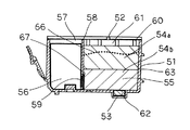
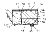
次に、第10の実施形態について図15,16を用いて説明する。図15は、本実施形態のインクタンク1の、鉛直面に沿った断面図であり、図16は、インクタンク1の吸収体室5の底面部分を、吸収部材を取り除いた状態で示す斜視図である。これらの図において第1の実施形態と同様の部分には同一の符号を付している。
Further, as shown in FIG. 14, the
(Tenth embodiment)
Next, a tenth embodiment will be described with reference to FIGS. FIG. 15 is a cross-sectional view of the
本実施形態では、インク導入路14を、底面に形成した凸部によって、その周囲に形成している。すなわち、吸収体室5の底面に凸部を形成すると、吸収部材4bを収容した際、吸収部材4bは、凸部によって変形させられ、凸部の周囲には空隙が形成される。本実施形態では、この空隙がインク導入路14として機能する。図16に示す例では、凸部として、連通部9から圧接体12側に向かって平行に延びる2つの凸部を形成しており、この構成では、特に、2つの凸部の間の部分をインク導入路14として有効に機能させることができる。
In the present embodiment, the
また、変形例として、吸収部材4bの底面を予め凹形状とし、この凹形状によって吸収体室5内に空隙が形成されるようにして、この空隙をインク導入路14として機能させてもよい。
As a modification, the bottom surface of the absorbing
また、本実施形態においても、吸収体室5の側部内壁に凸部を形成し、あるいは、吸収部材4bの側面に凹形状部を形成して、インク導入路14を側面に形成してもよいのはもちろんである。
Also in this embodiment, the
1 インクタンク(液体タンク)
2 大気連通口
3 インク供給口(液体供給口)
4a,4b 吸収部材
5 吸収体室
6 インク(液体)
7 インク導入路(液体導入路)
8 隔壁
9 連通部
1 Ink tank (liquid tank)
2
4a,
7 Ink introduction path (liquid introduction path)
8
Claims (5)
前記吸収体室と前記液体収容室とは、両者を連通させる連通部が形成された隔壁によって仕切られ、前記液体収容室から前記連通部および前記連通部の吸収体室側上端を介して液体が補給されるものであって、
前記液体供給口が配されている側面には凹凸状に構成された経路を備えて構成された液体タンクにおいて、
前記経路は、前記液体収容室内から前記吸収体室に渡って設けられており、前記経路の前記吸収体室側の端部の位置は、前記経路の圧接体側の端部(A)と該圧接体上面の前記経路側端部(B)との間に前記経路と前記圧接体とが直接連通しないために設けられた前記吸収体によって封止された封止領域を有する位置であることを特徴とする液体タンク。 A liquid supply port for supplying the liquid to the liquid body discharge recording head, an absorber chamber which houses the air vent, the absorbing member for absorbing and retaining liquid, the liquid to be supplied to the absorber chamber and housed directly to the liquid storage chamber has a pressure contact member exerts a strong holding force than the absorbent member in liquid in the liquid supply port is disposed in contact with the absorbing member,
Wherein the absorber chamber and the liquid chamber is partitioned by a partition wall communicating portion for communicating the two persons has been formed, from pre-Symbol liquid chamber the communicating portion and intake absorbent body chamber side upper end of the communicating portion Through which liquid is replenished ,
In the liquid tank configured to have a path configured to be uneven on the side surface on which the liquid supply port is arranged ,
Said path, said has a liquid storage chamber is provided across the absorber chamber, the position of the end of the absorber chamber side of said path, the end of the press body side of said path (A) and A position having a sealing region sealed by the absorber provided so that the path and the press contact body do not directly communicate with the path side end (B) on the upper surface of the press contact body. A liquid tank characterized by
Priority Applications (4)
| Application Number | Priority Date | Filing Date | Title |
|---|---|---|---|
| JP2004162957A JP4164471B2 (en) | 2004-06-01 | 2004-06-01 | Liquid tank and liquid discharge recording apparatus equipped with the liquid tank |
| US11/140,327 US7347541B2 (en) | 2004-06-01 | 2005-05-27 | Liquid tank |
| CNB200510073185XA CN100371172C (en) | 2004-06-01 | 2005-06-01 | Liquid tank |
| US11/961,818 US7686438B2 (en) | 2004-06-01 | 2007-12-20 | Liquid tank |
Applications Claiming Priority (1)
| Application Number | Priority Date | Filing Date | Title |
|---|---|---|---|
| JP2004162957A JP4164471B2 (en) | 2004-06-01 | 2004-06-01 | Liquid tank and liquid discharge recording apparatus equipped with the liquid tank |
Publications (3)
| Publication Number | Publication Date |
|---|---|
| JP2005342934A JP2005342934A (en) | 2005-12-15 |
| JP2005342934A5 JP2005342934A5 (en) | 2007-08-02 |
| JP4164471B2 true JP4164471B2 (en) | 2008-10-15 |
Family
ID=35424713
Family Applications (1)
| Application Number | Title | Priority Date | Filing Date |
|---|---|---|---|
| JP2004162957A Expired - Fee Related JP4164471B2 (en) | 2004-06-01 | 2004-06-01 | Liquid tank and liquid discharge recording apparatus equipped with the liquid tank |
Country Status (3)
| Country | Link |
|---|---|
| US (2) | US7347541B2 (en) |
| JP (1) | JP4164471B2 (en) |
| CN (1) | CN100371172C (en) |
Families Citing this family (8)
| Publication number | Priority date | Publication date | Assignee | Title |
|---|---|---|---|---|
| DE102007055163A1 (en) * | 2007-11-19 | 2009-05-20 | Pelikan Hardcopy Production Ag | Ink cartridge, in particular for an inkjet printer |
| CN106313903A (en) * | 2009-03-09 | 2017-01-11 | 惠普开发有限公司 | Ink supply container |
| CN201745248U (en) * | 2009-12-01 | 2011-02-16 | 孙荣华 | Ink box |
| CN202428825U (en) * | 2012-01-05 | 2012-09-12 | 深圳市打印王耗材有限公司 | Separated type ink cartridge of inkjet printer |
| JP6230231B2 (en) * | 2012-12-28 | 2017-11-15 | キヤノン株式会社 | Ink tank |
| JP2015077731A (en) * | 2013-10-17 | 2015-04-23 | キヤノン株式会社 | Ink filling device and ink filling method |
| CN107972364B (en) * | 2017-12-28 | 2019-11-05 | 杨晨晖 | Convenient for ink-cases of printers out of ink |
| JP2022184099A (en) * | 2021-05-31 | 2022-12-13 | キヤノン株式会社 | Recording device and recording head |
Family Cites Families (19)
| Publication number | Priority date | Publication date | Assignee | Title |
|---|---|---|---|---|
| JP2563769B2 (en) * | 1984-05-22 | 1996-12-18 | セイコーエプソン株式会社 | Printer ink tank |
| US6474798B1 (en) * | 1984-10-11 | 2002-11-05 | Seiko Epson Corporation | Ink supplied printer head and ink container |
| US4794409A (en) * | 1987-12-03 | 1988-12-27 | Hewlett-Packard Company | Ink jet pen having improved ink storage and distribution capabilities |
| IT1259361B (en) * | 1992-03-26 | 1996-03-12 | Olivetti & Co Spa | INK CONTAINER FOR AN INK JET PRINT HEAD |
| JP2951818B2 (en) | 1993-05-25 | 1999-09-20 | キヤノン株式会社 | Replaceable ink cartridge for inkjet |
| CA2290700C (en) | 1992-07-24 | 2004-08-31 | Canon Kabushiki Kaisha | Ink container, ink and ink jet recording apparatus using ink container |
| JP3187652B2 (en) | 1993-06-29 | 2001-07-11 | キヤノン株式会社 | Ink tank unit, inkjet cartridge having the ink tank unit, and inkjet apparatus having the inkjet cartridge |
| US6206514B1 (en) | 1993-06-29 | 2001-03-27 | Canon Kabushiki Kaisha | Ink tank unit, an ink jet cartridge having said ink tank unit and an ink jet apparatus having said ink jet cartridge |
| EP0691207B1 (en) | 1994-07-06 | 2001-11-07 | Canon Kabushiki Kaisha | Ink container, ink jet head having ink container, ink jet apparatus having ink container, and manufacturing method for ink container |
| JPH0820115A (en) | 1994-07-06 | 1996-01-23 | Canon Inc | Ink tank, ink jet head and ink jet device employing said tank |
| JP2570211B2 (en) * | 1995-05-25 | 1997-01-08 | セイコーエプソン株式会社 | Printer ink tank |
| JP3467676B2 (en) * | 1996-03-14 | 2003-11-17 | セイコーエプソン株式会社 | Ink jet recording device and ink cartridge |
| JP3281263B2 (en) | 1996-07-10 | 2002-05-13 | キヤノン株式会社 | Ink tank and ink jet recording apparatus provided with the ink tank |
| TW372219B (en) * | 1996-11-15 | 1999-10-21 | Canon Kk | Container for liquid to be ejected |
| MX9801290A (en) * | 1997-02-19 | 1998-11-30 | Canon Cabushiki Kaisha | Ink container and ink jet recording apparatus. |
| JP3287791B2 (en) * | 1997-07-30 | 2002-06-04 | キヤノン株式会社 | Liquid filling method and liquid filling device for liquid container having liquid container |
| JP3720586B2 (en) * | 1997-07-30 | 2005-11-30 | キヤノン株式会社 | Ink tank, ink absorber used in the ink tank, and ink tank manufacturing method |
| JP3278410B2 (en) | 1998-05-11 | 2002-04-30 | キヤノン株式会社 | Liquid container, method of manufacturing the container, package of the container, ink jet head cartridge integrating the container with a recording head, and liquid discharge recording apparatus |
| JP3647326B2 (en) * | 1999-08-24 | 2005-05-11 | キヤノン株式会社 | Liquid storage container, liquid discharge mechanism, and ink jet recording apparatus |
-
2004
- 2004-06-01 JP JP2004162957A patent/JP4164471B2/en not_active Expired - Fee Related
-
2005
- 2005-05-27 US US11/140,327 patent/US7347541B2/en not_active Expired - Fee Related
- 2005-06-01 CN CNB200510073185XA patent/CN100371172C/en not_active Expired - Fee Related
-
2007
- 2007-12-20 US US11/961,818 patent/US7686438B2/en not_active Expired - Fee Related
Also Published As
| Publication number | Publication date |
|---|---|
| CN100371172C (en) | 2008-02-27 |
| CN1733488A (en) | 2006-02-15 |
| JP2005342934A (en) | 2005-12-15 |
| US7347541B2 (en) | 2008-03-25 |
| US20080106582A1 (en) | 2008-05-08 |
| US7686438B2 (en) | 2010-03-30 |
| US20050264621A1 (en) | 2005-12-01 |
Similar Documents
| Publication | Publication Date | Title |
|---|---|---|
| KR0145750B1 (en) | Inkjet cartridge and its manufacturing method | |
| KR100710974B1 (en) | Ink reservoir for an inkjet printer | |
| JP3278410B2 (en) | Liquid container, method of manufacturing the container, package of the container, ink jet head cartridge integrating the container with a recording head, and liquid discharge recording apparatus | |
| KR100723563B1 (en) | Liquid supply system, ink tank, ink supply system, and inkjet recording apparatus | |
| JP3667296B2 (en) | Ink tank | |
| JP3658373B2 (en) | Liquid storage container, ink jet cartridge, and ink jet recording apparatus | |
| JP4047259B2 (en) | Ink supply system | |
| JP4882461B2 (en) | Filter device and droplet discharge device | |
| US7686438B2 (en) | Liquid tank | |
| JP2006281589A (en) | Liquid container and ink jet recorder | |
| US6193356B1 (en) | Ink jet recording device capable of reliably discharging air bubble during purging operations | |
| JP2009126086A (en) | Fluid discharge device and recording head | |
| JPH08150723A (en) | Ink jet apparatus and ink supply device used therein | |
| JP2004155182A (en) | Liquid injection apparatus | |
| JP3944192B2 (en) | Liquid tank | |
| JPH08323989A (en) | Ink cartridge, ink-jet recording device equipped with more than one said ink cartridge | |
| JP2019025663A (en) | Liquid storage container and liquid discharge device | |
| JP4557410B2 (en) | Sub ink tank, ink jet head cartridge, and ink jet recording apparatus | |
| JP4734710B2 (en) | Inkjet printer | |
| US11926164B2 (en) | Recording apparatus and recording head | |
| JP2003103794A (en) | Method for re-injecting ink and ink jet printer | |
| JP4487573B2 (en) | ink cartridge | |
| JP3977357B2 (en) | Ink cartridge and ink jet recording apparatus | |
| JP2005161636A (en) | Liquid supply system | |
| JP3684093B2 (en) | Liquid supply system, liquid storage container, head cartridge, and inkjet cartridge |
Legal Events
| Date | Code | Title | Description |
|---|---|---|---|
| A521 | Written amendment |
Free format text: JAPANESE INTERMEDIATE CODE: A523 Effective date: 20070615 |
|
| A977 | Report on retrieval |
Free format text: JAPANESE INTERMEDIATE CODE: A971007 Effective date: 20071025 |
|
| A131 | Notification of reasons for refusal |
Free format text: JAPANESE INTERMEDIATE CODE: A131 Effective date: 20071107 |
|
| A521 | Written amendment |
Free format text: JAPANESE INTERMEDIATE CODE: A523 Effective date: 20071207 |
|
| TRDD | Decision of grant or rejection written | ||
| A01 | Written decision to grant a patent or to grant a registration (utility model) |
Free format text: JAPANESE INTERMEDIATE CODE: A01 Effective date: 20080709 |
|
| A01 | Written decision to grant a patent or to grant a registration (utility model) |
Free format text: JAPANESE INTERMEDIATE CODE: A01 |
|
| A61 | First payment of annual fees (during grant procedure) |
Free format text: JAPANESE INTERMEDIATE CODE: A61 Effective date: 20080728 |
|
| FPAY | Renewal fee payment (event date is renewal date of database) |
Free format text: PAYMENT UNTIL: 20110801 Year of fee payment: 3 |
|
| R150 | Certificate of patent or registration of utility model |
Free format text: JAPANESE INTERMEDIATE CODE: R150 Ref document number: 4164471 Country of ref document: JP Free format text: JAPANESE INTERMEDIATE CODE: R150 |
|
| FPAY | Renewal fee payment (event date is renewal date of database) |
Free format text: PAYMENT UNTIL: 20120801 Year of fee payment: 4 |
|
| FPAY | Renewal fee payment (event date is renewal date of database) |
Free format text: PAYMENT UNTIL: 20120801 Year of fee payment: 4 |
|
| FPAY | Renewal fee payment (event date is renewal date of database) |
Free format text: PAYMENT UNTIL: 20130801 Year of fee payment: 5 |
|
| LAPS | Cancellation because of no payment of annual fees |