JP4163766B2 - Ink jet print head and method of manufacturing ink jet print head - Google Patents
Ink jet print head and method of manufacturing ink jet print head Download PDFInfo
- Publication number
- JP4163766B2 JP4163766B2 JP04228997A JP4228997A JP4163766B2 JP 4163766 B2 JP4163766 B2 JP 4163766B2 JP 04228997 A JP04228997 A JP 04228997A JP 4228997 A JP4228997 A JP 4228997A JP 4163766 B2 JP4163766 B2 JP 4163766B2
- Authority
- JP
- Japan
- Prior art keywords
- heating element
- surface portion
- defining
- chamber
- print head
- Prior art date
- Legal status (The legal status is an assumption and is not a legal conclusion. Google has not performed a legal analysis and makes no representation as to the accuracy of the status listed.)
- Expired - Fee Related
Links
- 238000004519 manufacturing process Methods 0.000 title claims description 7
- 238000010438 heat treatment Methods 0.000 claims description 59
- 238000007373 indentation Methods 0.000 claims description 34
- 238000002347 injection Methods 0.000 claims description 15
- 239000007924 injection Substances 0.000 claims description 15
- 239000007788 liquid Substances 0.000 claims description 12
- 239000000758 substrate Substances 0.000 claims description 12
- 238000000034 method Methods 0.000 claims description 10
- 239000007921 spray Substances 0.000 claims description 4
- 230000006911 nucleation Effects 0.000 description 20
- 238000010899 nucleation Methods 0.000 description 20
- 238000009835 boiling Methods 0.000 description 10
- 230000004888 barrier function Effects 0.000 description 8
- 238000010586 diagram Methods 0.000 description 8
- 230000015572 biosynthetic process Effects 0.000 description 6
- 230000007547 defect Effects 0.000 description 6
- 238000005530 etching Methods 0.000 description 6
- 239000010408 film Substances 0.000 description 6
- 238000002161 passivation Methods 0.000 description 6
- 230000001154 acute effect Effects 0.000 description 5
- 230000008569 process Effects 0.000 description 5
- 238000007641 inkjet printing Methods 0.000 description 3
- 238000010304 firing Methods 0.000 description 2
- 230000007246 mechanism Effects 0.000 description 2
- 229910004490 TaAl Inorganic materials 0.000 description 1
- XAGFODPZIPBFFR-UHFFFAOYSA-N aluminium Chemical compound [Al] XAGFODPZIPBFFR-UHFFFAOYSA-N 0.000 description 1
- 229910052782 aluminium Inorganic materials 0.000 description 1
- IZJSTXINDUKPRP-UHFFFAOYSA-N aluminum lead Chemical compound [Al].[Pb] IZJSTXINDUKPRP-UHFFFAOYSA-N 0.000 description 1
- 239000003086 colorant Substances 0.000 description 1
- 238000004891 communication Methods 0.000 description 1
- 230000001186 cumulative effect Effects 0.000 description 1
- 230000003111 delayed effect Effects 0.000 description 1
- 230000000694 effects Effects 0.000 description 1
- 239000012530 fluid Substances 0.000 description 1
- 230000006872 improvement Effects 0.000 description 1
- 239000000463 material Substances 0.000 description 1
- 238000007639 printing Methods 0.000 description 1
- 230000035945 sensitivity Effects 0.000 description 1
- 238000000926 separation method Methods 0.000 description 1
- 229910052715 tantalum Inorganic materials 0.000 description 1
- GUVRBAGPIYLISA-UHFFFAOYSA-N tantalum atom Chemical compound [Ta] GUVRBAGPIYLISA-UHFFFAOYSA-N 0.000 description 1
- 239000010409 thin film Substances 0.000 description 1
- 230000007704 transition Effects 0.000 description 1
Images


Classifications
-
- B—PERFORMING OPERATIONS; TRANSPORTING
- B41—PRINTING; LINING MACHINES; TYPEWRITERS; STAMPS
- B41J—TYPEWRITERS; SELECTIVE PRINTING MECHANISMS, i.e. MECHANISMS PRINTING OTHERWISE THAN FROM A FORME; CORRECTION OF TYPOGRAPHICAL ERRORS
- B41J2/00—Typewriters or selective printing mechanisms characterised by the printing or marking process for which they are designed
- B41J2/005—Typewriters or selective printing mechanisms characterised by the printing or marking process for which they are designed characterised by bringing liquid or particles selectively into contact with a printing material
- B41J2/01—Ink jet
- B41J2/135—Nozzles
- B41J2/16—Production of nozzles
- B41J2/1601—Production of bubble jet print heads
- B41J2/1603—Production of bubble jet print heads of the front shooter type
-
- B—PERFORMING OPERATIONS; TRANSPORTING
- B41—PRINTING; LINING MACHINES; TYPEWRITERS; STAMPS
- B41J—TYPEWRITERS; SELECTIVE PRINTING MECHANISMS, i.e. MECHANISMS PRINTING OTHERWISE THAN FROM A FORME; CORRECTION OF TYPOGRAPHICAL ERRORS
- B41J2/00—Typewriters or selective printing mechanisms characterised by the printing or marking process for which they are designed
- B41J2/005—Typewriters or selective printing mechanisms characterised by the printing or marking process for which they are designed characterised by bringing liquid or particles selectively into contact with a printing material
- B41J2/01—Ink jet
- B41J2/135—Nozzles
- B41J2/14—Structure thereof only for on-demand ink jet heads
- B41J2/14016—Structure of bubble jet print heads
- B41J2/14088—Structure of heating means
- B41J2/14112—Resistive element
- B41J2/1412—Shape
-
- B—PERFORMING OPERATIONS; TRANSPORTING
- B41—PRINTING; LINING MACHINES; TYPEWRITERS; STAMPS
- B41J—TYPEWRITERS; SELECTIVE PRINTING MECHANISMS, i.e. MECHANISMS PRINTING OTHERWISE THAN FROM A FORME; CORRECTION OF TYPOGRAPHICAL ERRORS
- B41J2/00—Typewriters or selective printing mechanisms characterised by the printing or marking process for which they are designed
- B41J2/005—Typewriters or selective printing mechanisms characterised by the printing or marking process for which they are designed characterised by bringing liquid or particles selectively into contact with a printing material
- B41J2/01—Ink jet
- B41J2/135—Nozzles
- B41J2/16—Production of nozzles
- B41J2/1621—Manufacturing processes
- B41J2/1626—Manufacturing processes etching
Landscapes
- Engineering & Computer Science (AREA)
- Manufacturing & Machinery (AREA)
- Particle Formation And Scattering Control In Inkjet Printers (AREA)
Description
【0001】
【発明の属する技術分野】
本発明は、サーマルインクジェットプリンティングに関し、より詳細には、サーマルインクジェット・プリントヘッドの加熱素子に関する。
【0002】
【従来の技術】
インクジェット・プリンティング機構は、着色剤の滴をプリント可能な表面上に噴射するペンを用いてイメージを生成する。かかる機構は、コンピュータのプリンタ、プロッタ、複写機およびファクシミリ等、広範囲の様々な用途に用いることができる。便宜上、本発明の概念は、プリンタの環境において説明する。インクジェット・プリンタは典型的には、多数の独立にアドレス指定することができる噴射ユニットを有するプリントヘッドを含む。各噴射ユニットは、共通のインク源と接続されたインク・チャンバおよびインク出口ノズルまたはオリフィスを含む。チャンバ内のトランスデューサが運動力(impetus)を与えて、インク滴がノズルを通って吐出される。
【0003】
サーマルインクジェット・ペンにおいて、トランスデューサは、チャンバ内のインクのごく一部が急速に気化して気泡が形成されるのに十分な熱を与える抵抗加熱素子である。この気泡が、液体のインク滴をノズルから吐出させる。プリンタ出力を均一で正確にするためには、気泡形成のタイミング、大きさ、速度、形状および位置ができるだけ均一であることが望ましい。異なる噴射ユニット間でおよび1つのノズルから連続して生じる滴の間での均一であることが望まれている。
【0004】
流体の沸騰特性に関係する均一性の問題がある。非均質核沸騰(heterogeneous nucleate boiling)または気泡核形成(bubble nucleation)は、一般に、加熱素子の表面または他の加熱される表面上の欠陥の場所で起こる。これらの欠陥は、亀裂、不連続面および複数の表面が角度をなして交わる縁や頂点である。非均質核沸騰は、十分な大きさの核形成位置が存在していないときにさらに熱エネルギが加えられた後に起こる均質つまり膜沸騰よりも、起こりやすい。従って、サーマルインクジェット・プリンティング中に起こる急速で均一性が変動しやすい沸騰の過程で最も大きな影響を及ぼすのは、非均質な核の形成である。
【0005】
【発明が解決しようとする課題】
現存するサーマルインクジェット・プリントヘッドも、核形成位置を提供する鋭角の縁部を有する単一の小さい凹部を備えるくぼみ(basin)を備えるように形成した加熱素子をそれぞれの噴射チャンバに設けることによって、少なくとも部分的には非均質核沸騰過程を制御している。このくぼみは、それぞれのオリフィスよりも小さく、各オリフィスと位置合わせすることにより、潜在的な核形成位置がすべてオリフィスの開口部分の真下になるようになっている。このようにすることにより、噴射チャンバによっては核形成位置が欠如し、均質核形成を行うためにより高いエネルギーが必要になるというリスクが回避される。これらの位置をオリフィスと合わせて慎重に位置決めすることによって、中心線からずれた意図しない欠陥によって噴射方向の軸から外れた(off axis)滴が噴射する可能性も少なくなる。しかし、このようにシステムを改良しても、これまでは、性能を理想的に均一化することができなかった。
【0006】
【課題を解決するための手段】
従来のシステムの均一性に関する欠点は、サーマルインクジェットにインク噴射チャンバおよびオリフィスを有する本体を設けることによって、低減または克服される。電気的に活性化された加熱素子が、噴射チャンバと熱的に連結する本体に接続され、少なくとも加熱素子の一部と同一の広がりを有する輪郭のある表面部(contoured surface portions)を含む。噴射チャンバの輪郭のある表面部は、複数のくぼみを有する。
【0007】
【実施例】
図1は、平坦な上側表面14を備える堅い平坦な基板12を有するサーマルインクジェット・プリントヘッド10を示す。基板の上側表面には、平坦な加熱素子16が設けられる。加熱素子16を取り囲む基板には、障壁層20が設けられており、障壁層20は、加熱素子の上に心合わせされた噴射チャンバ22を画定する。障壁層の上面には、噴射チャンバを囲むようにオリフィスプレート24が接続され、加熱素子の上に心合わせされたオリフィス26が画定される。噴射チャンバは、少なくとも一側面に、インク供給プレナム32によって供給されるインクの入口となる側面開口部30を少なくとも1つ有する。プリントヘッドは、加熱素子、チャンバおよびオリフィスが同じように配置され、共通のプレナムによってインクが供給される、噴射ユニットが隣接して延長されるアレイを含む。
【0008】
図2に示すように、加熱素子16は、基板12の上側表面14の上層にありインク滴を噴射ユニットから吐出しなければならない場合に加熱素子の両端に電圧を印加する電動の制御装置(図示せず)に接続されている、1組の導電性アルミニウム・リード34の間に接続されている。
【0009】
図3に示すように、加熱素子16は、平坦な下側表面36およびこれと平行な平坦な上側表面40を有する。加熱素子は、3層に積層されたものである。一番下の層は、基板の上側表面14に載置されるTaAlの抵抗薄膜37である。抵抗膜の上に、電気的に絶縁するパシベーション層38があり、パシベーション層の上に、機械的に保護するタンタルのキャビテーション・バリヤ39がある。キャビテーション・バリヤ39は、抵抗膜を気泡形成の応力から保護し、プリンティング中につぶれることを防ぐ。
【0010】
複数の分離しているの四方形のくぼみ42が、加熱素子16の表面の大部分を横切って延びているアレイ内に画定される。これらのくぼみは、加熱素子の上側表面および下側表面と平行な平坦な底面又は床44を有し、パシベーション層38がくぼみ内で露出しないように限られた深さだけ延びている。他の実施例においては、パシベーション層は露出していてもよい。それぞれのくぼみの周辺は、くぼみの床44のレベルと加熱素子の上側表面40の間に段を提供する垂直の側壁46によって画定されている。側壁46がくぼみの床44と交わるところは、鋭角部または内部縁50になっており、上側表面40と交わるところは、リム縁52である。両方の縁はともに鋭い直角であるが、この変形も以下に説明する。実際は、エッチング工程に生来の制約があるために、鋭い縁はわずかに丸みがついている。これらの鋭い縁によって、沸騰が最も急速にすすみ、最も低いエネルギにおいて起こる傾向がある核形成位置53が提供される。さらに、くぼみの床における厚さを薄くすることにより、より抵抗膜に近くなりキャビテーション・バリヤ39を横切る熱勾配が低くなるため、より高い熱が与えられ、下側の核形成位置50における沸騰をさらに促進することができる。
【0011】
好適な実施例において、くぼみ42は格子上に配置され、個々のくぼみは交互にチェッカー盤になるように配置されている。くぼみはそれぞれ、その上にくぼみが配置されている格子のピッチと等しいかそれよりも小さい幅および長さを有し、それぞれのくぼみの角において間隔が空き、隣接するくぼみの角と交差しないようになっている。加熱素子を基板に設けた後にくぼみを形成するのに用いるエッチング工程によって、上から見て角に丸みのあるくぼみが生じるので、くぼみの幅と同じピッチを有する格子上に配置されたくぼみ同士であっても分離が提供される。好適な実施例において、くぼみの幅は5から10μmの間であるが、本発明の利点は、さらなる小型化が実現するにつれてはっきりと理解される。図示の実施例においては13個のくぼみが設けられているが、他の配置においては、これよりも多くのまたは少ないくぼみを設けてもよい。
【0012】
図4ないし図8は、他の加熱素子表面の輪郭パターン(countour patterns)を示す。図4は、それぞれが好適な実施例のくぼみ42と同様の断面を有する同心のリング型のくぼみ56のパターンを有する加熱素子を有する他のプリントヘッドを示す。外側リングは大きく、それぞれのリングは、与えられた加熱素子の主要な(major)面積に対して、かなりの長さの縁50、52を有することによって、多くのくぼみの機能を果たして多くの核形成位置を提供する。図示のパターンを、同じ領域にわたって同様のくぼみおよびランド幅(land widths)を有する渦巻き型を形成するように変更することも可能である。かかるくぼみは、厳密な意味では複数の凹みではないが、縁50、52における加熱素子およびくぼんでいる領域の全体の面積および長さ寸法に対する割合が高いので、本願では「複数」と考える。。本出願においては、単一の「くぼみ」またはくぼみ部分は、その周辺の半分より多くを取り囲む縁を有する、水盤形、ポケット、チャネル、溝またはそれらの部分として画定される。従って、細長いチャネルは、それぞれの長さがその幅よりもわずかに長いだけの多数の個々のくぼみに分離していると解してもよい。
【0013】
図5に示すように、他の実施例の加熱素子は、平行なチャネル62によって画定される長方形に配列された個別の四方形の台地60を有する。図4に関して上で触れたように、累加された台地の縁の長さは、同じ面積の四方形、円、楕円(oblong)または同様の簡単な形の単一の規則的なくぼみの縁の長さを累加したものよりもはるかに大きいので、チャネルの格子は複数のくぼみとみなされる。
【0014】
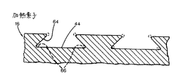
好適な実施例は、側壁が垂直で縦断面が長方形のくぼみに関して説明しているが、図6、図7、図8は他のチャネルの縦断面を示す。図6において、側壁64はアンダーカットされ、側壁が平坦な床44に対して鋭角をなすように設けられている。鋭角の側の核形成位置66は、少なくとも部分的に側壁の下に配置されており、核形成を向上される。側壁は、効果的であれば、鈍角を含むいかなる量だけ垂直からずれてもよい。図7は、図6のアンダーカットの代替例を示しており、この例において、従来のエッチング工程によって、縦断面が少なくとも縁において曲線状のつまり楕円形のチャネル70が形成される。核形成位置72は、図6の核形成位置と同様に配置されるが、図示のエッチング技術によって上側縁52をより鋭角にして核形成をさらに促進してもよい。
【0015】
図8は、さらなる他の実施例を示す。本実施例において、加熱素子の表面40はほぼ平坦な平面であり、表面を横切って突出した隆起部74が間隔をおいて配列されている。図8の実施例の隆起部および図5および図6の実施例のくぼみはすべて、上述した図1ないし図5に示すいずれのパターンに形成してもよい。
【0016】
従来例の動作
図9Aないし図9Dは、従来のサーマルインクジェット・プリントヘッド110の制限を示す。プリントヘッド110は、輪郭をとる表面の代わりに表面が平坦な加熱素子を有しているということを除いては、本発明の好適な実施例とほぼ同一に構成されている。従来のプリントヘッド110は、1組の噴射チャンバ112、114を有する。チャンバ114において、加熱素子には、オリフィス122を通る中央軸120からでたらめにずれた、意図しない欠陥である亀裂116がある。右側の噴射チャンバ114内の加熱素子にはこのような欠陥がない。その結果、図9Bに示すように、エネルギを両方の加熱素子に同時に印加すると、まず最初に左側のチャンバ112内の欠陥116において気泡124が核形成される。核形成位置がないとより高いエネルギが必要であるため、右側のチャンバではまだ気泡の形成が開始されていない。
【0017】
図9Cに示すように、左側の気泡124は、左側のオリフィス122から滴126を追い出すことを開始するのに十分なだけ成長している。一方で、右側のチャンバ内でも気泡130ができているが、こちらは、核形成位置の助けなしで気泡形成を開始するにはより高いエネルギが必要なために遅れて形成されたので、左側の気泡120よりも小さい。図9Dにおいて、左側の滴は、気泡の位置が中心からずれていたために、軸から外れた経路を通って噴射される。左側の滴126は、プリント媒体(図示せず)と衝突するよう意図された位置から、空間的に外れている。右側の滴132は、たまたま軸を通って噴出されているが、その本来の位置からは時間的に外れている。プリントヘッドがプリント媒体の上を急速に横切ると、遅れた滴は、プリントヘッドの経路に沿って、適時に吐出される場合にデポジットされるよりも予定経路からより遠く外れてデポジットされる。
【0018】
好適な実施例の動作
図10Aないし図10Dに示すように、好適な実施例は、時間的にも空間的にも滴が外れることがない。図10Bにおいて、核形成は、多くのまたは大部分のくぼみ42で起こる。核形成がすべての予定位置、またはすべてのくぼみで起こらない場合であっても、十分な数のくぼみおよび形成位置があるので、少なくともいくつかの核形成位置においては素早く気泡形成が開始され、時間的に外れることが回避される。また、位置の数が多いことによって、すべての位置が核形成に効果的ではない場合であっても、結果として生じる気泡がうまく分配されることが保証されて、空間的に外れることも回避される。くぼみの量が多く広範囲に分配されていることによって、核沸騰から膜沸騰への遷移が加速され、さらに均一性が改善される。
【0019】
図10は、大部分またはすべてのくぼみ42内で形成される小さな気泡82を示す。図10Dにおいて、気泡82はそれぞれの噴射チャンバ内で合体している。結果として得られる気泡84の表面つまり「波面」は従来の気泡よりも平坦で、滴86を高い信頼性で軸を通って噴射する。平坦な波面にすることによって、オリフィスの位置の感度が低減される。これは、球状に膨張している気泡に関してわずかに軸がずれてオリフィスが位置することによってオリフィス近くのインク内に乱流や側方流動が生成される可能性がある従来のシステムよりも、改良されたところである。
【0020】
好適な実施例において、加熱素子16全体の厚さは約8〜10μmである。通常、抵抗膜37の厚さは0.10μm、パシベーション38の厚さは0.75μm、そしてキャビテーション・バリヤ39の厚さは0.6μmである。アルミニウムのリード線34は、厚さが約0.7μmであり、抵抗層とパッシベーション層の間に配置される。典型的な用途において、隣接する噴射ユニットは、中心において40〜80μmの間隔をおいて配置されており、それぞれのオリフィスは直径が10〜50μmであり、加熱素子の上に14〜25μmの間隔をあけて配置されている。加熱素子は、一辺が約20〜60μmの四方形であり、噴射チャンバは抵抗層よりも幅または直径が約16μm大きい。くぼみは、抵抗層およびその他の層のフォトイメージング(phtoimaging)を連続して行った後でバリヤおよびオリフィスプレートを付加する前にエッチングによって形成されるが、キャビテーション・バリヤを次の2段階でイメージを生成してもよい。最初に、連続した平坦な層を生成し、次に、くぼみを規定する多孔性の層を生成する。
【0021】
以上、本発明の実施例について詳述したが、以下、本発明の各実施態様の例を示す。
(実施態様1)
基板を設け、基板に加熱素子を設け、第1のレベルにある複数の第1の表面部おびこれと異なる第2のレベルにある複数の第2の表面部を有する輪郭を備える表面を加熱素子に形成する工程を含むインクジェット・プリントヘッドの製造方法。
(実施態様2)
輪郭を備える表面を形成する工程は、加熱素子から材料を除去することを含む前項1に記載のインクジェット・プリントヘッドの製造方法。
(実施態様3)
輪郭を備える表面を形成する工程は、前記加熱素子をエッチングすることを含む前項1または2に記載のインクジェット・プリントヘッドの製造方法。
(実施態様4)
輪郭を備える表面を形成する工程は、それぞれが第1の表面部と第2の表面部の間の境界を画定する複数の縁を画定することを含む前項1ないし3のいずれかに記載のインクジェット・プリントヘッドの製造方法。
(実施態様5)
複数の縁を画定する工程は、縁の下に溝が規定されるように第1の表面部にアンダーカットを施すことを含む前項4に記載のインクジェット・プリントヘッドの製造方法。
(実施態様6)
複数のインク噴射チャンバを画定する本体と、前記本体は、前記各発射チャンバについて、前記噴射チャンバから前記プリントヘッドの外側に液体を伝達するオリフィスを画定するものであり、
電気的に稼動される複数の加熱素子とを含み、
前記各加熱素子は、前記各噴射チャンバと熱を伝達する前記本体と接続されており、前記各加熱素子は、前記噴射チャンバの輪郭のある表面部を画定する輪郭のある表面を有するものであり、前記噴射チャンバの各表面部は、第1のレベルにある第1の表面部およびこれと異なる第2のレベルにある第2の表面部のパターンを備えることを特徴とするインクジェット・プリントヘッド。
(実施態様7)
第2の表面部が、隣接する表面部からある角度ずれた縁壁部を少なくとも1つ有する縁壁で第1の表面部と接することを特徴とする前項6に記載のインクジェット・プリントヘッド。
(実施態様8)
壁部が隣接する表面部の少なくとも1つから、少なくとも90度ずれており、縁壁部が隣接する表面部の少なくとも1つと垂直または鋭角をなすようになっていることを特徴とする前項6または7に記載のインクジェット・プリントヘッド。
(実施態様9)
加熱素子のそれぞれが略同一の輪郭のある表面パターンを有しており、均一の加熱性能が与えられるようになっていることを特徴とする前項6ないし8のいずれかに記載のインクジェット・プリントヘッド。
(実施態様10)
第2の表面部が等間隔をおいて配置されており規則的なを形成していることを特徴とする前項9に記載のインクジェット・プリントヘッド。
【0022】
【発明の効果】
以上、説明したように、本発明では、加熱素子の表面に複数のくぼみを設け、気泡の核が生成される位置を提供することで均一量の気泡を均一の時間で生成することができる。したがって、一定のインク滴を噴射することができ、プリント品質を向上させる。
【0023】
開示は好適なおよび他の実施例に関して説明しているが、本発明はこれによって限定されることを意図するものではない。
【図面の簡単な説明】
【図1】本発明の一実施例であるインクジェット・プリントヘッドの部分概略図。
【図2】図1の2−2線側断面図。
【図3】図1の2−2線拡大側断面図である。
【図4】本発明の他の実施例であるインクジェット・プリントヘッドの部分断面図。
【図5】本発明の他の実施例であるインクジェット・プリントヘッドの部分断面図。
【図6】本発明の他の実施例であるインクジェット・プリントヘッドの部分断面図。
【図7】本発明の他の実施例であるインクジェット・プリントヘッドの部分断面図。
【図8】本発明の他の実施例であるインクジェット・プリントヘッドの部分断面図。
【図9A】従来装置の動作を説明する図。
【図9B】従来装置の動作を説明する図。
【図9C】従来装置の動作を説明する図。
【図9D】従来装置の動作を説明する図。
【図10A】図1に示される実施例の動作を説明する図。
【図10B】図1に示される実施例の動作を説明する図。
【図10C】図1に示される実施例の動作を説明する図。
【図10D】図1に示される実施例の動作を説明する図。
【符号の説明】
10:インクジェット・プリントヘッド
12:基板
16:加熱素子
22:噴射チャンバ
26:オリフィス
42:くぼみ
50:核形成位置[0001]
BACKGROUND OF THE INVENTION
The present invention relates to thermal inkjet printing, and more particularly to a heating element for a thermal inkjet printhead.
[0002]
[Prior art]
Inkjet printing mechanisms generate images using a pen that ejects drops of colorant onto a printable surface. Such a mechanism can be used in a wide variety of applications such as computer printers, plotters, copiers and facsimiles. For convenience, the inventive concept will be described in a printer environment. Inkjet printers typically include a printhead having a number of independently addressable ejection units. Each ejection unit includes an ink chamber and an ink outlet nozzle or orifice connected to a common ink source. Transducers in the chamber provide impetus and ink drops are ejected through the nozzles.
[0003]
In a thermal ink jet pen, the transducer is a resistive heating element that provides enough heat to rapidly vaporize a small portion of the ink in the chamber and form bubbles. This bubble causes a liquid ink droplet to be ejected from the nozzle. In order to make the printer output uniform and accurate, it is desirable that the timing, size, speed, shape and position of bubble formation be as uniform as possible. It is desirable to be uniform between different jetting units and between successive drops from one nozzle.
[0004]
There are uniformity issues related to the boiling characteristics of the fluid. Heterogeneous nucleate boiling or bubble nucleation generally occurs at the location of defects on the surface of the heating element or other heated surface. These defects are cracks, discontinuities and edges or vertices where multiple surfaces meet at an angle. Inhomogeneous nucleate boiling is more likely to occur than homogeneous or film boiling that occurs after additional thermal energy is applied when a sufficiently large nucleation site is not present. Therefore, it is the formation of non-homogeneous nuclei that has the greatest impact on the rapid and volatile boiling process that occurs during thermal ink jet printing.
[0005]
[Problems to be solved by the invention]
Existing thermal ink jet printheads also have heating elements formed in each firing chamber that are formed to have a basin with a single small recess with sharp edges that provide a nucleation position. At least partially controls the heterogeneous nucleate boiling process. The indentations are smaller than the respective orifices and are aligned with each orifice so that all potential nucleation positions are directly below the orifice opening. In this way, the risk of lacking nucleation positions in some injection chambers and requiring higher energy to perform homogeneous nucleation is avoided. Careful positioning of these positions with the orifices also reduces the possibility of ejecting drops off axis due to unintentional defects off the center line. However, even if the system is improved in this way, until now, it has not been possible to ideally equalize the performance.
[0006]
[Means for Solving the Problems]
The drawbacks associated with the uniformity of conventional systems are reduced or overcome by providing a thermal inkjet with a body having an ink ejection chamber and an orifice. An electrically activated heating element is connected to a body that is in thermal communication with the injection chamber and includes at least contoured surface portions that are coextensive with a portion of the heating element. The contoured surface of the injection chamber has a plurality of indentations.
[0007]
【Example】
FIG. 1 shows a
[0008]
As shown in FIG. 2, the
[0009]
As shown in FIG. 3, the
[0010]
A plurality of separate
[0011]
In the preferred embodiment, the
[0012]
4 to 8 show other heating element surface contour patterns. FIG. 4 shows another printhead having heating elements each having a pattern of concentric ring-shaped
[0013]
As shown in FIG. 5, the heating element of another embodiment has individual
[0014]
Although the preferred embodiment is described with respect to a recess having a vertical sidewall and a rectangular longitudinal section, FIGS. 6, 7 and 8 show longitudinal sections of other channels. In FIG. 6, the
[0015]
FIG. 8 shows yet another embodiment. In this embodiment, the
[0016]
9A through 9D illustrate the limitations of a conventional thermal inkjet printhead 110. FIG. The print head 110 is constructed substantially the same as the preferred embodiment of the present invention except that it has a heating element with a flat surface instead of a contoured surface. A conventional printhead 110 has a set of
[0017]
As shown in FIG. 9C, the
[0018]
Operation of the Preferred Embodiment As shown in FIGS. 10A-10D, the preferred embodiment does not drop in time or space. In FIG. 10B, nucleation occurs in many or most of the
[0019]
FIG. 10 shows small bubbles 82 formed in most or all of the
[0020]
In a preferred embodiment, the total thickness of the
[0021]
As mentioned above, although the Example of this invention was explained in full detail, the example of each embodiment of this invention is shown below.
(Embodiment 1)
A heating element having a substrate, a heating element provided on the substrate, and a plurality of first surface portions at a first level and a contour having a plurality of second surface portions at a second level different from the first surface portion. A method for manufacturing an ink jet print head, comprising a step of forming the ink jet print head.
(Embodiment 2)
2. The method of manufacturing an ink jet print head according to item 1, wherein the step of forming the surface having the contour includes removing material from the heating element.
(Embodiment 3)
3. The method of manufacturing an ink jet print head according to item 1 or 2, wherein the step of forming a surface having a contour includes etching the heating element.
(Embodiment 4)
The inkjet according to any of the preceding clauses, wherein the step of forming a surface with a contour includes defining a plurality of edges each defining a boundary between the first surface portion and the second surface portion. -Printhead manufacturing method.
(Embodiment 5)
5. The method of manufacturing an ink jet print head according to item 4, wherein the step of defining the plurality of edges includes undercutting the first surface portion so that a groove is defined under the edges.
(Embodiment 6)
A body defining a plurality of ink ejection chambers, the body defining, for each firing chamber, an orifice for transferring liquid from the ejection chamber to the outside of the printhead;
A plurality of electrically operated heating elements,
Each of the heating elements is connected to the main body for transferring heat to each of the spray chambers, and each of the heating elements has a contoured surface that defines a contoured surface portion of the spray chamber. An inkjet printhead wherein each surface portion of the ejection chamber comprises a pattern of a first surface portion at a first level and a second surface portion at a second level different from the first surface portion.
(Embodiment 7)
7. The ink jet print head according to item 6, wherein the second surface portion is in contact with the first surface portion at an edge wall having at least one edge wall portion that is offset from the adjacent surface portion by an angle.
(Embodiment 8)
6. The preceding item 6 or 6, wherein the wall portion is offset by at least 90 degrees from at least one of the adjacent surface portions, and the edge wall portion forms a perpendicular or acute angle with at least one of the adjacent surface portions. 8. An inkjet printhead according to item 7.
(Embodiment 9)
9. The ink jet print head according to any one of the preceding items 6 to 8, wherein each of the heating elements has a surface pattern having substantially the same contour so as to provide uniform heating performance. .
(Embodiment 10)
10. The ink jet print head according to item 9, wherein the second surface portions are arranged at regular intervals to form a regular shape.
[0022]
【The invention's effect】
As described above, in the present invention, it is possible to generate a uniform amount of bubbles in a uniform time by providing a plurality of depressions on the surface of the heating element and providing a position where the core of the bubble is generated. Therefore, a constant ink droplet can be ejected, and the print quality is improved.
[0023]
Although the disclosure has been described with reference to preferred and other embodiments, the invention is not intended to be limited thereby.
[Brief description of the drawings]
FIG. 1 is a partial schematic view of an ink jet print head according to an embodiment of the present invention.
2 is a side sectional view taken along line 2-2 of FIG. 1;
3 is an enlarged side sectional view taken along line 2-2 of FIG.
FIG. 4 is a partial sectional view of an ink jet print head according to another embodiment of the present invention.
FIG. 5 is a partial sectional view of an ink jet print head according to another embodiment of the present invention.
FIG. 6 is a partial sectional view of an ink jet print head according to another embodiment of the present invention.
FIG. 7 is a partial sectional view of an ink jet print head according to another embodiment of the present invention.
FIG. 8 is a partial sectional view of an ink jet print head according to another embodiment of the present invention.
FIG. 9A is a diagram illustrating the operation of a conventional device.
FIG. 9B is a diagram for explaining the operation of the conventional apparatus.
FIG. 9C is a diagram for explaining the operation of the conventional apparatus.
FIG. 9D is a diagram for explaining the operation of the conventional apparatus.
10A is a diagram for explaining the operation of the embodiment shown in FIG. 1; FIG.
FIG. 10B is a diagram for explaining the operation of the embodiment shown in FIG. 1;
FIG. 10C is a diagram for explaining the operation of the embodiment shown in FIG. 1;
FIG. 10D is a diagram for explaining the operation of the embodiment shown in FIG. 1;
[Explanation of symbols]
10: Inkjet print head 12: Substrate 16: Heating element 22: Injection chamber 26: Orifice 42: Recess 50: Nucleation position
Claims (12)
前記噴射チャンバから前記プリントヘッドの外側に液体を伝達し、第1の平面に垂直な噴射方向軸を画定するオリフィスを画定する前記本体と、
前記本体に接続され、前記噴射チャンバ内の液体に熱を直接伝達する発熱抵抗体の加熱素子であって、前記液体に熱を提供して前記噴射チャンバ内で前記液体の一部を急速に気化させるように構成された加熱素子と、
前記加熱素子の少なくとも一部と同一の広がりを有する輪郭のある表面部を含む前記噴射チャンバと、
第1の平面に平行で、噴射方向に垂直な第2の平面を占有する前記輪郭のある表面部の少なくとも大きな部分と、
前記輪郭のある表面部と合わせられるオリフィスと、
平行で、離間する平面を占有する複数のくぼみ及び複数の隆起部分を画定する前記噴射チャンバの輪郭のある表面部と、
を備えていることを特徴とするサーマルインクジェット・プリントヘッド。A body defining an ink ejection chamber comprising:
The body defining an orifice for transferring liquid from the ejection chamber to the outside of the print head and defining an ejection direction axis perpendicular to a first plane;
A heating element of a heating resistor connected to the body and directly transferring heat to the liquid in the ejection chamber , providing heat to the liquid to rapidly vaporize a part of the liquid in the ejection chamber A heating element configured to cause
The spray chamber including a contoured surface having the same extent as at least a portion of the heating element;
At least a large portion of the contoured surface portion occupying a second plane parallel to the first plane and perpendicular to the injection direction;
An orifice mated with the contoured surface;
A contoured surface portion of the injection chamber defining a plurality of indentations and a plurality of raised portions that occupy parallel, spaced planes;
A thermal ink jet print head characterized by comprising:
噴射チャンバ内の液体に熱を直接伝達して前記噴射チャンバ内で液体の一部を急速に気化させるように構成された発熱抵抗体である少なくとも1つの加熱素子を基板に設ける工程と、
第1のレベルにある複数の第1の表面部およびこれと異なる第2のレベルにある複数の第2の表面部を有する、前記加熱素子の輪郭を備えた表面を形成し、前記加熱素子の大きな平面に平行に広がる複数のくぼみを画定する工程と、
垂直な噴射方向軸を有するオリフィスを画定するプレートを前記基板に接続するものであって、輪郭のある表面と交差するように前記噴射方向軸を位置合わせし、前記噴射方向軸が前記大きな面に垂直となり、前記加熱素子から離間しチャンバを画定するように前記プレートを向ける工程と、
を含むことを特徴とするサーマルインクジェット・プリントヘッドを製造する方法。Providing a substrate;
Providing at least one heating element on the substrate that is a heating resistor configured to directly transfer heat to the liquid in the ejection chamber to rapidly vaporize a portion of the liquid in the ejection chamber;
Forming a surface with a contour of the heating element, having a plurality of first surface portions at a first level and a plurality of second surface portions at a second level different from the first surface portion; Defining a plurality of indentations extending parallel to a large plane;
A plate defining an orifice having a vertical injection direction axis is connected to the substrate, wherein the injection direction axis is aligned to intersect a contoured surface, and the injection direction axis is aligned with the large surface. Directing the plate to be vertical and spaced from the heating element to define a chamber;
A method of manufacturing a thermal ink jet printhead comprising:
発熱抵抗体である複数の加熱素子とを備え、
前記本体は、前記各噴射チャンバについて、前記噴射チャンバから前記プリントヘッドの外側に液体を伝達し、噴射方向軸の中心に置かれ、噴射方向軸に垂直なオリフィスを画定するものであり、
前記各加熱素子は、液体に熱を提供して前記各噴射チャンバ内で前記液体の一部を急速に気化させるように構成され、前記各加熱素子は、前記各噴射チャンバ内の液体に熱を直接伝達すべく前記本体に接続されており、前記各加熱素子は、それぞれのオリフィスと合わせられた前記噴射チャンバの輪郭のある表面部を画定する輪郭のある表面を有するものであり、
前記各噴射チャンバの輪郭のある各表面部は、前記噴射方向軸から傾斜して偏位される複数の輪郭特徴を画定している、
ことを特徴とするサーマルインクジェット・プリントヘッド。A body defining a plurality of ink ejection chambers;
A plurality of heating elements that are heating resistors ,
The body transmits liquid from the ejection chamber to the outside of the printhead for each of the ejection chambers, is positioned in the center of the ejection direction axis and defines an orifice perpendicular to the ejection direction axis;
Each heating element is configured to provide heat to the liquid to rapidly vaporize a portion of the liquid in each ejection chamber, and each heating element provides heat to the liquid in each ejection chamber . is connected to the main body so as to transfer directly the respective heating element, which has a surface with a contour that defines the surface portion with a contour of the ejection chamber, which is combined with each of the orifices,
Each contoured surface portion of each injection chamber defines a plurality of contour features that are offset from the injection direction axis.
A thermal ink jet print head characterized by the above.
Applications Claiming Priority (2)
| Application Number | Priority Date | Filing Date | Title |
|---|---|---|---|
| US60645996A | 1996-03-04 | 1996-03-04 | |
| US606,459 | 1996-03-04 |
Publications (2)
| Publication Number | Publication Date |
|---|---|
| JPH09239985A JPH09239985A (en) | 1997-09-16 |
| JP4163766B2 true JP4163766B2 (en) | 2008-10-08 |
Family
ID=24428067
Family Applications (1)
| Application Number | Title | Priority Date | Filing Date |
|---|---|---|---|
| JP04228997A Expired - Fee Related JP4163766B2 (en) | 1996-03-04 | 1997-02-26 | Ink jet print head and method of manufacturing ink jet print head |
Country Status (4)
| Country | Link |
|---|---|
| US (1) | US6485128B1 (en) |
| EP (1) | EP0794057B1 (en) |
| JP (1) | JP4163766B2 (en) |
| DE (1) | DE69622147T2 (en) |
Cited By (2)
| Publication number | Priority date | Publication date | Assignee | Title |
|---|---|---|---|---|
| US8390276B2 (en) | 2010-09-27 | 2013-03-05 | Bourns Incorporated | Target magnet assembly for a sensor used with a steering gear |
| US8448528B2 (en) | 2010-09-27 | 2013-05-28 | Bourns Incorporated | Three-piece torque sensor assembly |
Families Citing this family (9)
| Publication number | Priority date | Publication date | Assignee | Title |
|---|---|---|---|---|
| US6293654B1 (en) | 1998-04-22 | 2001-09-25 | Hewlett-Packard Company | Printhead apparatus |
| US6331049B1 (en) | 1999-03-12 | 2001-12-18 | Hewlett-Packard Company | Printhead having varied thickness passivation layer and method of making same |
| JP4521930B2 (en) * | 2000-04-28 | 2010-08-11 | 京セラ株式会社 | Inkjet head |
| US7025894B2 (en) | 2001-10-16 | 2006-04-11 | Hewlett-Packard Development Company, L.P. | Fluid-ejection devices and a deposition method for layers thereof |
| US6755509B2 (en) * | 2002-11-23 | 2004-06-29 | Silverbrook Research Pty Ltd | Thermal ink jet printhead with suspended beam heater |
| JP2005205721A (en) * | 2004-01-22 | 2005-08-04 | Sony Corp | Liquid discharge head and liquid discharge device |
| US7703891B2 (en) * | 2005-12-07 | 2010-04-27 | Samsung Electronics Co., Ltd. | Heater to control bubble and inkjet printhead having the heater |
| EP2978609B1 (en) * | 2013-07-29 | 2021-04-21 | Hewlett-Packard Development Company, L.P. | Fluid ejection device and a method of manufacturing a fluid ejection device |
| US11155085B2 (en) * | 2017-07-17 | 2021-10-26 | Hewlett-Packard Development Company, L.P. | Thermal fluid ejection heating element |
Family Cites Families (24)
| Publication number | Priority date | Publication date | Assignee | Title |
|---|---|---|---|---|
| JPS5931943B2 (en) | 1979-04-02 | 1984-08-06 | キヤノン株式会社 | liquid jet recording method |
| US4336548A (en) | 1979-07-04 | 1982-06-22 | Canon Kabushiki Kaisha | Droplets forming device |
| US4490728A (en) * | 1981-08-14 | 1984-12-25 | Hewlett-Packard Company | Thermal ink jet printer |
| US4514741A (en) | 1982-11-22 | 1985-04-30 | Hewlett-Packard Company | Thermal ink jet printer utilizing a printhead resistor having a central cold spot |
| EP0124312A3 (en) | 1983-04-29 | 1985-08-28 | Hewlett-Packard Company | Resistor structures for thermal ink jet printers |
| US4513298A (en) | 1983-05-25 | 1985-04-23 | Hewlett-Packard Company | Thermal ink jet printhead |
| US4894664A (en) * | 1986-04-28 | 1990-01-16 | Hewlett-Packard Company | Monolithic thermal ink jet printhead with integral nozzle and ink feed |
| DE3717294C2 (en) * | 1986-06-10 | 1995-01-26 | Seiko Epson Corp | Ink jet recording head |
| JPS6334144A (en) | 1986-07-29 | 1988-02-13 | Canon Inc | Liquid jet recording head |
| US4792818A (en) * | 1987-06-12 | 1988-12-20 | International Business Machines Corporation | Thermal drop-on-demand ink jet print head |
| US4794411A (en) | 1987-10-19 | 1988-12-27 | Hewlett-Packard Company | Thermal ink-jet head structure with orifice offset from resistor |
| US4870433A (en) | 1988-07-28 | 1989-09-26 | International Business Machines Corporation | Thermal drop-on-demand ink jet print head |
| JPH02103150A (en) | 1988-10-12 | 1990-04-16 | Rohm Co Ltd | Ink jet recording head |
| DE69020864T2 (en) | 1989-02-28 | 1995-12-14 | Canon Kk | INK-JET HEAD WITH HEAT-GENERATING RESISTOR MADE OF NON-MONOCRYSTALLINE SUBSTANCE CONTAINING IRIDIUM, TANTALUM AND ALUMINUM, AND INK-JET PRINTING DEVICE EQUIPPED WITH SUCH HEAD. |
| US4935752A (en) | 1989-03-30 | 1990-06-19 | Xerox Corporation | Thermal ink jet device with improved heating elements |
| JPH03213355A (en) * | 1990-01-19 | 1991-09-18 | Fuji Xerox Co Ltd | Ink jet print head |
| JPH0733091B2 (en) | 1990-03-15 | 1995-04-12 | 日本電気株式会社 | INKJET RECORDING METHOD AND INKJET HEAD USING THE SAME |
| US5041844A (en) | 1990-07-02 | 1991-08-20 | Xerox Corporation | Thermal ink jet printhead with location control of bubble collapse |
| US5169806A (en) | 1990-09-26 | 1992-12-08 | Xerox Corporation | Method of making amorphous deposited polycrystalline silicon thermal ink jet transducers |
| JP3054450B2 (en) | 1991-02-13 | 2000-06-19 | 株式会社リコー | Base for liquid jet recording head and liquid jet recording head |
| JPH04307252A (en) * | 1991-04-05 | 1992-10-29 | Matsushita Electric Ind Co Ltd | Ink jet head |
| JPH04338609A (en) | 1991-05-16 | 1992-11-25 | Matsushita Electric Ind Co Ltd | Solenoid driving circuit |
| JPH06183001A (en) * | 1992-12-18 | 1994-07-05 | Canon Inc | Thermal ink jet head |
| EP0638424A3 (en) * | 1993-08-09 | 1996-07-31 | Hewlett Packard Co | Thermal ink jet printhead and method of manufacture. |
-
1996
- 1996-09-20 DE DE69622147T patent/DE69622147T2/en not_active Expired - Lifetime
- 1996-09-20 EP EP96306875A patent/EP0794057B1/en not_active Expired - Lifetime
-
1997
- 1997-02-26 JP JP04228997A patent/JP4163766B2/en not_active Expired - Fee Related
- 1997-10-07 US US08/946,523 patent/US6485128B1/en not_active Expired - Fee Related
Cited By (2)
| Publication number | Priority date | Publication date | Assignee | Title |
|---|---|---|---|---|
| US8390276B2 (en) | 2010-09-27 | 2013-03-05 | Bourns Incorporated | Target magnet assembly for a sensor used with a steering gear |
| US8448528B2 (en) | 2010-09-27 | 2013-05-28 | Bourns Incorporated | Three-piece torque sensor assembly |
Also Published As
| Publication number | Publication date |
|---|---|
| US6485128B1 (en) | 2002-11-26 |
| DE69622147D1 (en) | 2002-08-08 |
| JPH09239985A (en) | 1997-09-16 |
| DE69622147T2 (en) | 2002-11-14 |
| EP0794057B1 (en) | 2002-07-03 |
| EP0794057A1 (en) | 1997-09-10 |
Similar Documents
| Publication | Publication Date | Title |
|---|---|---|
| US6331055B1 (en) | Inkjet printhead with top plate bubble management | |
| US6966112B2 (en) | Methods of fabricating FIT firing chambers of different drop weights on a single printhead | |
| JP3231786B2 (en) | High-resolution matrix inkjet device | |
| EP1563999B1 (en) | High-density drop generating printhead | |
| JP3196631B2 (en) | Ink jet print head | |
| EP1894727A2 (en) | Liquid jet head | |
| US7484835B2 (en) | Filter plate usable with an ink jet head, an ink jet head with the filter plate, and a method of fabricating the filter plate | |
| JP2006123551A (en) | Nozzle plate, inkjet printing head with the same and manufacturing method of nozzle plate | |
| JPH05201003A (en) | Roof shooter type thermal ink jet printing head | |
| JPS6280054A (en) | Ink jet type printing head with built-in filter and manufacture thereof | |
| JP2006123550A (en) | Nozzle plate, inkjet printing head with the same, and manufacturing method of nozzle plate | |
| JP4163766B2 (en) | Ink jet print head and method of manufacturing ink jet print head | |
| AU2005211710A1 (en) | High resolution ink jet printhead | |
| US6971736B2 (en) | Ink jet record head | |
| US4740800A (en) | Liquid jet recording head | |
| US6132033A (en) | Inkjet print head with flow control manifold and columnar structures | |
| KR100875810B1 (en) | Thermal ink jet defect tolerant resistor design | |
| JPH07205423A (en) | Ink-jet print head | |
| JP2012179889A (en) | Method of manufacturing inkjet recording head, recording element substrate, and the inkjet recording head | |
| JP2004209741A (en) | Inkjet recording head | |
| US6132034A (en) | Ink jet print head with flow control contour | |
| US7478476B2 (en) | Methods of fabricating fit firing chambers of different drop wights on a single printhead | |
| JP3870062B2 (en) | Inkjet recording head | |
| JPS634955A (en) | Liquid jet recording head | |
| JP3638356B2 (en) | Inkjet head |
Legal Events
| Date | Code | Title | Description |
|---|---|---|---|
| A521 | Request for written amendment filed |
Free format text: JAPANESE INTERMEDIATE CODE: A523 Effective date: 20040224 |
|
| A621 | Written request for application examination |
Free format text: JAPANESE INTERMEDIATE CODE: A621 Effective date: 20040224 |
|
| A131 | Notification of reasons for refusal |
Free format text: JAPANESE INTERMEDIATE CODE: A131 Effective date: 20070105 |
|
| A601 | Written request for extension of time |
Free format text: JAPANESE INTERMEDIATE CODE: A601 Effective date: 20070327 |
|
| A602 | Written permission of extension of time |
Free format text: JAPANESE INTERMEDIATE CODE: A602 Effective date: 20070405 |
|
| A521 | Request for written amendment filed |
Free format text: JAPANESE INTERMEDIATE CODE: A523 Effective date: 20070628 |
|
| A131 | Notification of reasons for refusal |
Free format text: JAPANESE INTERMEDIATE CODE: A131 Effective date: 20080401 |
|
| A521 | Request for written amendment filed |
Free format text: JAPANESE INTERMEDIATE CODE: A523 Effective date: 20080605 |
|
| TRDD | Decision of grant or rejection written | ||
| A01 | Written decision to grant a patent or to grant a registration (utility model) |
Free format text: JAPANESE INTERMEDIATE CODE: A01 Effective date: 20080627 |
|
| A01 | Written decision to grant a patent or to grant a registration (utility model) |
Free format text: JAPANESE INTERMEDIATE CODE: A01 |
|
| A61 | First payment of annual fees (during grant procedure) |
Free format text: JAPANESE INTERMEDIATE CODE: A61 Effective date: 20080725 |
|
| FPAY | Renewal fee payment (event date is renewal date of database) |
Free format text: PAYMENT UNTIL: 20110801 Year of fee payment: 3 |
|
| R150 | Certificate of patent or registration of utility model |
Free format text: JAPANESE INTERMEDIATE CODE: R150 |
|
| FPAY | Renewal fee payment (event date is renewal date of database) |
Free format text: PAYMENT UNTIL: 20110801 Year of fee payment: 3 |
|
| FPAY | Renewal fee payment (event date is renewal date of database) |
Free format text: PAYMENT UNTIL: 20120801 Year of fee payment: 4 |
|
| FPAY | Renewal fee payment (event date is renewal date of database) |
Free format text: PAYMENT UNTIL: 20130801 Year of fee payment: 5 |
|
| FPAY | Renewal fee payment (event date is renewal date of database) |
Free format text: PAYMENT UNTIL: 20130801 Year of fee payment: 5 |
|
| S111 | Request for change of ownership or part of ownership |
Free format text: JAPANESE INTERMEDIATE CODE: R313113 |
|
| FPAY | Renewal fee payment (event date is renewal date of database) |
Free format text: PAYMENT UNTIL: 20130801 Year of fee payment: 5 |
|
| R350 | Written notification of registration of transfer |
Free format text: JAPANESE INTERMEDIATE CODE: R350 |
|
| R250 | Receipt of annual fees |
Free format text: JAPANESE INTERMEDIATE CODE: R250 |
|
| LAPS | Cancellation because of no payment of annual fees |