JP4163618B2 - Video encoding / transmission system, video encoding / transmission method, encoding apparatus, decoding apparatus, encoding method, decoding method, and program suitable for use in the same - Google Patents
Video encoding / transmission system, video encoding / transmission method, encoding apparatus, decoding apparatus, encoding method, decoding method, and program suitable for use in the same Download PDFInfo
- Publication number
- JP4163618B2 JP4163618B2 JP2003526167A JP2003526167A JP4163618B2 JP 4163618 B2 JP4163618 B2 JP 4163618B2 JP 2003526167 A JP2003526167 A JP 2003526167A JP 2003526167 A JP2003526167 A JP 2003526167A JP 4163618 B2 JP4163618 B2 JP 4163618B2
- Authority
- JP
- Japan
- Prior art keywords
- prediction mode
- prediction
- image block
- related information
- mode
- Prior art date
- Legal status (The legal status is an assumption and is not a legal conclusion. Google has not performed a legal analysis and makes no representation as to the accuracy of the status listed.)
- Expired - Lifetime
Links
Images


Classifications
-
- H—ELECTRICITY
- H04—ELECTRIC COMMUNICATION TECHNIQUE
- H04N—PICTORIAL COMMUNICATION, e.g. TELEVISION
- H04N19/00—Methods or arrangements for coding, decoding, compressing or decompressing digital video signals
- H04N19/50—Methods or arrangements for coding, decoding, compressing or decompressing digital video signals using predictive coding
- H04N19/503—Methods or arrangements for coding, decoding, compressing or decompressing digital video signals using predictive coding involving temporal prediction
- H04N19/51—Motion estimation or motion compensation
- H04N19/513—Processing of motion vectors
- H04N19/517—Processing of motion vectors by encoding
-
- H—ELECTRICITY
- H04—ELECTRIC COMMUNICATION TECHNIQUE
- H04N—PICTORIAL COMMUNICATION, e.g. TELEVISION
- H04N19/00—Methods or arrangements for coding, decoding, compressing or decompressing digital video signals
- H04N19/10—Methods or arrangements for coding, decoding, compressing or decompressing digital video signals using adaptive coding
- H04N19/102—Methods or arrangements for coding, decoding, compressing or decompressing digital video signals using adaptive coding characterised by the element, parameter or selection affected or controlled by the adaptive coding
- H04N19/103—Selection of coding mode or of prediction mode
- H04N19/105—Selection of the reference unit for prediction within a chosen coding or prediction mode, e.g. adaptive choice of position and number of pixels used for prediction
-
- H—ELECTRICITY
- H04—ELECTRIC COMMUNICATION TECHNIQUE
- H04N—PICTORIAL COMMUNICATION, e.g. TELEVISION
- H04N19/00—Methods or arrangements for coding, decoding, compressing or decompressing digital video signals
- H04N19/10—Methods or arrangements for coding, decoding, compressing or decompressing digital video signals using adaptive coding
- H04N19/102—Methods or arrangements for coding, decoding, compressing or decompressing digital video signals using adaptive coding characterised by the element, parameter or selection affected or controlled by the adaptive coding
- H04N19/103—Selection of coding mode or of prediction mode
- H04N19/107—Selection of coding mode or of prediction mode between spatial and temporal predictive coding, e.g. picture refresh
-
- H—ELECTRICITY
- H04—ELECTRIC COMMUNICATION TECHNIQUE
- H04N—PICTORIAL COMMUNICATION, e.g. TELEVISION
- H04N19/00—Methods or arrangements for coding, decoding, compressing or decompressing digital video signals
- H04N19/10—Methods or arrangements for coding, decoding, compressing or decompressing digital video signals using adaptive coding
- H04N19/134—Methods or arrangements for coding, decoding, compressing or decompressing digital video signals using adaptive coding characterised by the element, parameter or criterion affecting or controlling the adaptive coding
- H04N19/136—Incoming video signal characteristics or properties
- H04N19/14—Coding unit complexity, e.g. amount of activity or edge presence estimation
-
- H—ELECTRICITY
- H04—ELECTRIC COMMUNICATION TECHNIQUE
- H04N—PICTORIAL COMMUNICATION, e.g. TELEVISION
- H04N19/00—Methods or arrangements for coding, decoding, compressing or decompressing digital video signals
- H04N19/10—Methods or arrangements for coding, decoding, compressing or decompressing digital video signals using adaptive coding
- H04N19/169—Methods or arrangements for coding, decoding, compressing or decompressing digital video signals using adaptive coding characterised by the coding unit, i.e. the structural portion or semantic portion of the video signal being the object or the subject of the adaptive coding
- H04N19/17—Methods or arrangements for coding, decoding, compressing or decompressing digital video signals using adaptive coding characterised by the coding unit, i.e. the structural portion or semantic portion of the video signal being the object or the subject of the adaptive coding the unit being an image region, e.g. an object
- H04N19/176—Methods or arrangements for coding, decoding, compressing or decompressing digital video signals using adaptive coding characterised by the coding unit, i.e. the structural portion or semantic portion of the video signal being the object or the subject of the adaptive coding the unit being an image region, e.g. an object the region being a block, e.g. a macroblock
-
- H—ELECTRICITY
- H04—ELECTRIC COMMUNICATION TECHNIQUE
- H04N—PICTORIAL COMMUNICATION, e.g. TELEVISION
- H04N19/00—Methods or arrangements for coding, decoding, compressing or decompressing digital video signals
- H04N19/46—Embedding additional information in the video signal during the compression process
-
- H—ELECTRICITY
- H04—ELECTRIC COMMUNICATION TECHNIQUE
- H04N—PICTORIAL COMMUNICATION, e.g. TELEVISION
- H04N19/00—Methods or arrangements for coding, decoding, compressing or decompressing digital video signals
- H04N19/50—Methods or arrangements for coding, decoding, compressing or decompressing digital video signals using predictive coding
- H04N19/503—Methods or arrangements for coding, decoding, compressing or decompressing digital video signals using predictive coding involving temporal prediction
- H04N19/51—Motion estimation or motion compensation
- H04N19/527—Global motion vector estimation
-
- H—ELECTRICITY
- H04—ELECTRIC COMMUNICATION TECHNIQUE
- H04N—PICTORIAL COMMUNICATION, e.g. TELEVISION
- H04N19/00—Methods or arrangements for coding, decoding, compressing or decompressing digital video signals
- H04N19/50—Methods or arrangements for coding, decoding, compressing or decompressing digital video signals using predictive coding
- H04N19/593—Methods or arrangements for coding, decoding, compressing or decompressing digital video signals using predictive coding involving spatial prediction techniques
-
- H—ELECTRICITY
- H04—ELECTRIC COMMUNICATION TECHNIQUE
- H04N—PICTORIAL COMMUNICATION, e.g. TELEVISION
- H04N19/00—Methods or arrangements for coding, decoding, compressing or decompressing digital video signals
- H04N19/60—Methods or arrangements for coding, decoding, compressing or decompressing digital video signals using transform coding
- H04N19/61—Methods or arrangements for coding, decoding, compressing or decompressing digital video signals using transform coding in combination with predictive coding
-
- H—ELECTRICITY
- H04—ELECTRIC COMMUNICATION TECHNIQUE
- H04N—PICTORIAL COMMUNICATION, e.g. TELEVISION
- H04N19/00—Methods or arrangements for coding, decoding, compressing or decompressing digital video signals
- H04N19/70—Methods or arrangements for coding, decoding, compressing or decompressing digital video signals characterised by syntax aspects related to video coding, e.g. related to compression standards
-
- H—ELECTRICITY
- H04—ELECTRIC COMMUNICATION TECHNIQUE
- H04N—PICTORIAL COMMUNICATION, e.g. TELEVISION
- H04N19/00—Methods or arrangements for coding, decoding, compressing or decompressing digital video signals
- H04N19/80—Details of filtering operations specially adapted for video compression, e.g. for pixel interpolation
- H04N19/82—Details of filtering operations specially adapted for video compression, e.g. for pixel interpolation involving filtering within a prediction loop
Landscapes
- Engineering & Computer Science (AREA)
- Multimedia (AREA)
- Signal Processing (AREA)
- Compression Or Coding Systems Of Tv Signals (AREA)
Description
【0001】
【発明の属する技術分野】
本発明は、動画像符号化伝送システム、動画像符号化伝送方法、これらに用いて好適な符号化装置及び復号化装置、符号化方法、復号化方法及びプログラムに関する。
【0002】
【従来の技術】
従来の動画像符号化伝送システムで用いられる符号化装置及び復号化装置の一つの例について、図1及び図2を参照にして説明する。図1は、従来の動画像符号化伝送システムで用いられる符号化装置の概略構成を示す図であり、図2は、従来の動画像符号化伝送システムで用いられる復号化装置の概略構成を示す図である。
【0003】
図1に示す符号化装置120及び図2に示す復号化装置140は、ITU-T Recommendation H.263“Video coding for low bit rate communication”に記載のH.263符号化方式に準拠したディジタル動画像符号化装置及びディジタル動画像復号化装置である。
【0004】
符号化装置120は、動き補償フレーム間予測により時間方向に存在する冗長度を削減し、直交変換(例えば、DCT:Discrete Cosine Transform)により空間方向に存在する冗長度を削減することで、ディジタル動画像である入力映像信号2の情報圧縮符号化を行う。
【0005】
入力部121は、入力映像信号2、すなわち、フレーム画像の時間系列を受信する。ここで、符号化装置120において、現在、符号化対象となっているフレーム画像を「現フレーム」と呼ぶ。
【0006】
入力部121は、「現フレーム」を、16×16画素の正方矩形領域(「マクロブロック(第1の画像ブロック)」)に分割して、分割した「マクロブロック」を、順次、動き検出部122及び減算部124に送信する。ここで、現在、符号化対象となっている「マクロブロック」を「現マクロブロック」と呼ぶ。
【0007】
動き検出部122は、マクロブロック単位で、「動きベクトル」の検出と「マクロブロックモード(後述)」の決定とを行う。
【0008】
動き検出部122は、フレームメモリ132に格納されている過去の符号化済みフレーム画像(「参照フレーム」と呼ぶ)の所定の探索範囲において、現マクロブロックに類似する部分(「動き予測データ」)を見つけ出し、現マクロブロックから「動き予測データ」への二次元の空間的移動量を「動きベクトル」として検出する。
【0009】
動き検出部122は、例えば、「ブロックマッチング」を用いて、上述の「動きベクトル」の検出を行うことができる。すなわち、動き検出部122は、フレームメモリ132内の「参照フレーム」に、現マクロブロックの空間位置を中心とした探索範囲を設け、当該探索範囲内の画像データと現マクロブロックとの間で「差分二乗和」若しくは「差分絶対和」を算出する。そして、動き検出部122は、算出した「差分二乗和」若しくは「差分絶対和」を最小とする当該探索範囲内の画像データを「動き予測データ」として求め、現マクロブロックから「動き予測データ」への二次元の空間的移動量を「動きベクトル」として検出する。
【0010】
動き検出部122は、検出した「動きベクトル」を、動き補償部123及び可変長符号化部127に送信する。
【0011】
また、動き検出部122は、現マクロブロックにおいて適用される「マクロブロックモード」を決定する。ここで、「マクロブロックモード」は、現マクロブロックについての「予測残差信号(後述)」を生成する方法(「予測モード」や動きベクトルの数等)を示すものであって、図3に示すように、「INTRAモード(フレーム内予測モードを適用)」、「INTERモード(フレーム間予測モードを適用)」及び「INTER4Vモード(4つの動きベクトルによるフレーム間予測モードを適用)」を含む。
【0012】
また、「予測モード」は、現マクロブロックについて、時間方向の冗長度を削減する「フレーム間予測モード」を適用するか、もしくは空間方向の冗長度を削減する「フレーム内予測モード」を適用するかを示すものである。
【0013】
具体的には、動き検出部122は、検出された「動きベクトル」に基づいて、「INTRAモード」と「INTERモード」と「INTER4Vモード」との中から、予測残差信号(後述)の電力が最も小さくなる「マクロブロックモード」を選択する。
【0014】
動き検出部122は、決定した「マクロブロックモード」を、動き補償部123及び可変長符号化部127に送信する。
【0015】
動き補償部123は、動き検出部122から送信された「マクロブロックモード」及び「動きベクトル」に基づいて得られた「制御情報」を、減算部124に送信する。
【0016】
例えば、動き補償部123は、動き検出部122から送信された「マクロブロックモード」が「INTRAモード」である場合、「予測画像ブロック(後述)」を形成することなく、すなわち、動き補償部123が「現マクロブロック」に対して動き補償フレーム間予測を行うことなく、受信した「マクロブロックモード(INTRAモード)」のみを「制御情報」として、減算部124に通知する。
【0017】
また、動き補償部123は、動き検出部122から送信された「マクロブロックモード」が「INTERモード」又は「INTER4Vモード」である場合、動き検出部122から送信された「動きベクトル」とフレームメモリ132に格納されている参照フレームとを用いて、現マクロブロックに対して動き補償フレーム間予測を行い、「予測画像ブロック」を形成する。
【0018】
ここで、「INTERモード」では、16×16画素のマクロブロックにつき、1つの動きベクトルが割り当てられており、「INTER4Vモード」では、8×8画素のサブブロックにつき、1つの動きベクトルが割り当てられている。
【0019】
動き補償部123は、「制御情報」として、「予測画像ブロック」と「マクロブロックモード」と「動きベクトル」とを減算部124に送信する。また、動き補償部123は、「予測画像ブロック」を加算部131に送信する。
【0020】
減算部124は、動き補償部123により送信された「制御情報」に応じて、所定の情報を直交変換部125に送信する。
【0021】
具体的には、減算部124は、「マクロブロックモード」が「INTERモード」又は「INTER4Vモード」である場合、入力部124により送信された「現マクロブロック」と、動き補償部123から送信された「予測画像ブロック」との差分を求めることによって、時間的に連続する「マクロブロック」間の時間方向に存在する冗長度を削減する。
【0022】
ここで、減算部124によって求められた差分を「予測残差信号」と呼ぶ。減算部124は、かかる「予測残差信号」を直交変換部125に送信する。
【0023】
また、減算部124は、「マクロブロックモード」が「INTRAモード」である場合、動き補償部123から「予測画像ブロック」が送信されないため、入力部124から送信された「現マクロブロック」を「予測残差信号」として直交変換部125に送信する。
【0024】
直交変換部125は、減算部124により送信された「予測残差信号」を、8×8画素のサブブロック単位で、直交変換(例えば、DCT変換)することによって、「予測残差信号」内の空間方向に存在する冗長度を削減する。
【0025】
直交変換部125は、直交変換によって得られた「直交変換係数(例えば、DCT係数)」を量子化部126に送信する。
【0026】
量子化部126は、直交変換部125により送信された「直交変換係数」を量子化する。また、量子化部126は、量子化によって得られた「量子化直交変換係数」を、可変長符号化部127及び逆量子化部129に送信する。
【0027】
可変長符号化部127は、量子化部126により送信された「量子化直交変換係数」と、動き検出部122から送信された「動きベクトル」及び「マクロブロックモード」とを可変長符号化して圧縮ビットストリーム3に多重化する。可変長符号化部127は、圧縮ビットストリーム3を出力部128に送信する。
【0028】
出力部128は、可変長符号化部127により送信された圧縮ビットストリーム3を、1つ又は複数のフレーム画像分まとめて、ネットワーク1に伝送する。
【0029】
逆量子化部129は、量子化部126により送信された「量子化直交変換係数」を逆量子化し、得られた「直交変換係数」を逆直交変換部130に送信する。
【0030】
逆直交変換部130は、逆量子化部129により送信された「直交変換係数」を、逆直交変換(例えば、逆DCT変換)し、逆直交変換により得られた「予測残差信号」を加算部131に送信する。
【0031】
加算部131は、動き補償部123により送信された「予測画像ブロック」と、逆直交変換部130により送信された「予測残差信号」を加算することによって得られた結果を、フレームメモリ132に送信する。
【0032】
ただし、「マクロブロックモード」として「INTRAモード」が選択されている場合、動き補償部123によって「予測画像ブロック」が生成されない(動き補償フレーム間予測が行われない)ため、加算部131は、逆直交変換部130により送信された「予測残差信号(入力部121により送信された現マクロブロック)」をフレームメモリ132に送信する。
【0033】
フレームメモリ132は、加算部131により送信された情報(現マクロブロック)に基づいて「参照フレーム」を構成し記憶する。フレームメモリ132は、動き検出部122及び動き補償部123に「参照フレーム」を送信する。
【0034】
図2に示す復号化装置140は、符号化装置120により送信された圧縮ビットストリーム3から出力映像信号4を再生するものである。
【0035】
入力部141は、圧縮ビットストリーム3を受信し、可変長復号化部142に送信する。
【0036】
可変長復号化部142は、入力部141により送信された圧縮ビットストリーム3において、各フレーム画像の先頭から、マクロブロックごとに、「量子化直交変換係数」と「動きベクトル」と「マクロブロックモード」とを復号化する。
【0037】
可変長復号化部142は、復号化した「量子化直交変換係数」を逆量子化部143に送信する。また、可変長復号化部142は、復号化した「マクロブロックモード」が「INTERモード」又は「INTER4Vモード」である場合、復号化した「動きベクトル」及び「マクロブロックモード」を動き補償部145に送信する。
【0038】
逆量子化部143は、可変長復号化部142により送信された「量子化直交変換係数」を逆量子化することによって「直交変換係数」を得て、かかる「直交変換係数」を逆直交変換部144に送信する。
【0039】
逆直交変換部144は、逆量子化部143により送信された「直交変換係数」を逆直交変換することによって「予測残差信号」を得て、かかる「予測残差信号」を加算部146に送信する。
【0040】
動き補償部145は、フレームメモリ147に格納されている参照フレームと、可変長復号化部142により送信された「動きベクトル」及び「マクロブロックモード」とに基づいて「予測画像ブロック」を生成し、生成した「予測画像ブロック」を加算部146に送信する。
【0041】
加算部146は、逆直交変換部144により送信された「予測残差信号」と、動き補償部145により送信された「予測画像ブロック」とを加算することによって、出力映像信号4を構成するマクロブロックを生成して出力部148に送信する。
【0042】
ただし、「マクロブロックモード」が「INTRAモード」である場合、動き補償部145により「予測画像ブロック」が送信されないため、加算部146は、逆直交変換部144により送信された「予測残差信号」を、出力映像信号4を構成するマクロブロックとして出力部148に送信する。
【0043】
フレームメモリ147は、加算部146により送信された情報(マクロブロック)に基づいて「参照フレーム」を構成して記憶する。フレームメモリ147は、動き補償部145に「参照フレーム」を送信する。
【0044】
出力部148は、加算部146により送信された情報(マクロブロック)に基づいて出力映像信号4を構成して所定の表示タイミングで表示デバイス(図示せず)に出力する。
【0045】
上述のように、従来の動画像符号化伝送システムでは、マクロブロック単位で「マクロブロックモード」を決定するとともに、マクロブロックごとに設定される「符号化情報(動きベクトルや量子化パラメータ等)」を共通化して符号化処理を行うことにより、符号化効率を高めていた。
【0046】
【発明が解決しようとする課題】
しかしながら、従来の動画像符号化伝送システムでは、一つのマクロブロックに対して複数の「マクロブロックモード」を設定することができないため、図4のように、1つのマクロブロック内に、「フレーム内予測モード」で符号化処理したほうが良い部分(鳥の部分)と、「フレーム間予測モード」で符号化処理したほうが良い部分(雲の部分)とが混在していると、効率の良い符号化処理を行うことができないという問題点があった。
【0047】
この問題点を解決するために、マクロブロックの大きさを小さくし、「マクロブロックモード」の選択を切り替える単位を細かくする方法も考えられる。しかしながら、この方法では、マクロブロックの数が増加し、符号化処理に必要なマクロブロック毎の符号化情報を送る頻度も増加するため、符号化効率が低下してしまうという問題点があった。
【0048】
そこで、本発明は、以上の点に鑑みてなされたもので、マクロブロックの大きさや枠組みは変えずに、一つのマクロブロック内で、「マクロブロックモード」の切り替えを行い、「フレーム内予測モード」で符号化処理する部分と「フレーム間予測モード」で符号化処理する部分とを混在させることを可能とすることを目的とする。
【0049】
【課題を解決するための手段】
本発明の第1の特徴は、動画像を第1の画像ブロック単位で符号化する符号化装置であって、前記第1の画像ブロックを分割した第2の画像ブロック単位で、時間方向の冗長度を削除する第1の予測モードを適用するか、又は、空間方向の冗長度を削減する第2の予測モードを適用するかを示す予測モード選択情報を生成する予測モード選択情報生成手段と、選択された前記第1又は第2の予測モードを前記第2の画像ブロックに適用することにより予測残差信号を生成する予測残差信号生成手段と、前記予測モード選択情報及び前記予測残差信号を符号化して伝送する伝送手段とを具備することを要旨とする。
【0050】
本発明の第1の特徴において、前記伝送手段が、前記第1又は第2の予測モードによる符号化処理を行うために必要な予測モード関連情報を符号化して伝送することが好ましい。
【0051】
また、本発明の第1の特徴において、前記予測残差信号生成手段が、前記第1の予測モードを適用することが選択された場合、前記第2の画像ブロックごとに、動きベクトルを用いた動き補償フレーム間予測により前記予測残差信号を生成し、前記予測残差信号生成手段が、前記第2の予測モードを適用することが選択された場合、前記第2の画像ブロックごとに、フレーム内予測により前記予測残差信号を生成することが好ましい。
【0052】
また、本発明の第1の特徴において、前記伝送手段が、前記第1の予測モードを適用することが選択された場合、前記予測モード関連情報として、前記動きベクトルを示す情報を符号化して伝送することが好ましい。
【0053】
また、本発明の第1の特徴において、前記予測残差信号生成手段が、前記第1の画像ブロック内で、同一の動きベクトルを用いた動き補償フレーム間予測により前記予測残差信号を生成することが好ましい。
【0054】
また、本発明の第1の特徴において、前記伝送手段が、前記予測モード関連情報より先に、前記予測モード選択情報を伝送することが好ましい。
【0055】
また、本発明の第1の特徴において、前記予測残差信号生成手段が、前記第2の予測モードを適用することが選択された場合、前記第2の画像ブロックごとに、該第2の画像ブロックに隣接する画素値を用いた画素値予測方法により前記予測残差信号を生成し、前記伝送手段が、前記予測モード関連情報として、前記画素値予測方法を符号化して伝送することが好ましい。
【0056】
また、本発明の第1の特徴において、前記伝送手段が、前記予測モード関連情報を前記予測モード選択情報に関連付けて符号化して伝送することが好ましい。
【0057】
また、本発明の第1の特徴において、前記伝送手段が、前記第2の画像ブロック単位で、前記第1の予測モードが適用されていない場合、前記第1の予測モードの前記予測モード関連情報を伝送しないことが好ましい。
【0058】
本発明の第2の特徴は、動画像を復号化する復号化装置であって、動画像を分割した第1の画像ブロックを分割した第2の画像ブロック単位で、時間方向の冗長度を削除する第1の予測モードを適用するか、又は、空間方向の冗長度を削減する第2の予測モードを適用するかを示す予測モード選択情報を復号化する予測モード選択情報復号化手段と、前記予測モード選択情報により選択された前記第1又は第2の予測モードに基づいて、前記第2の画像ブロック単位で、前記動画像を復号化する動画像復号化手段とを具備することを要旨とする。
【0059】
本発明の第2の特徴において、前記第1又は第2の予測モードによる符号化処理に必要な予測モード関連情報を復号化する予測モード関連情報復号化手段を具備し、前記動画像復号化手段が、前記予測モード関連情報を用いて前記動画像を復号化することが好ましい。
【0060】
また、本発明の第2の特徴において、前記動画像復号化手段が、前記予測モード選択情報により前記第1の予測モードが適用されることが選択された場合、動き補償フレーム間予測を用いて前記動画像を復号化し、前記動画像復号化手段が、前記予測モード選択情報により前記第2の予測モードが適用されることが選択された場合、フレーム内予測を用いて前記動画像を復号化することが好ましい。
【0061】
また、本発明の第2の特徴において、前記予測モード関連情報復号化手段が、前記予測モード選択情報により前記第1の予測モードが適用されることが選択された場合、前記予測モード関連情報として、動きベクトルを示す情報を復号化することが好ましい。
【0062】
また、本発明の第2の特徴において、前記予測モード選択情報復号化手段が、前記予測モード関連情報より先に、前記予測モード選択情報を復号化することが好ましい。
【0063】
また、本発明の第2の特徴において、前記動画像復号化手段が、前記予測モード選択情報により前記第1の予測モードを適用することが選択された場合、前記第1の画像ブロック単位で、同一の動きベクトルによる動き補償フレーム間予測を用いて前記動画像を復号化することが好ましい。
【0064】
また、本発明の第2の特徴において、前記予測モード選択情報復号化手段が、前記予測モード選択情報により前記第2の予測モードを適用することが選択された場合、前記予測モード関連情報として、前記第2の画像ブロックに係る画素値予測方法を復号化し、前記動画像復号化手段が、前記画素値予測方法を用いて前記動画像を復号化することが好ましい。
【0065】
また、本発明の第2の特徴において、前記予測モード選択情報復号化手段が、前記第2の画像ブロック単位で、前記予測モード選択情報を復号化することが好ましい。
【0066】
また、本発明の第2の特徴において、前記予測モード選択情報が、前記予測モード関連情報に関連付けられて符号化されていることが好ましい。
【0067】
また、本発明の第2の特徴において、前記予測モード選択情報復号化手段が、前記第2の画像ブロック単位で、前記予測モード選択情報により前記第1の予測モードが適用されていないことが示されている場合、前記第1の予測モードの予測モード関連情報を復号化しないことが好ましい。
【0068】
本発明の第3の特徴は、動画像を第1の画像ブロック単位で符号化する符号化方法であって、前記第1の画像ブロックを分割した第2の画像ブロック単位で、時間方向の冗長度を削除する第1の予測モードを適用するか、又は、空間方向の冗長度を削減する第2の予測モードを適用するかを示す予測モード選択情報を生成する工程Aと、選択された前記第1又は第2の予測モードを前記第2の画像ブロックに適用することにより予測残差信号を生成する工程Bと、前記予測モード選択情報及び前記予測残差信号を符号化して伝送する工程Cとを有することを要旨とする。
【0069】
本発明の第3の特徴において、前記工程Cで、前記第1又は第2の予測モードによる符号化処理を行うために必要な予測モード関連情報を符号化して伝送することが好ましい。
【0070】
また、本発明の第3の特徴において、前記工程Bで、前記第1の予測モードを適用することが選択された場合、前記第2の画像ブロックごとに、動きベクトルを用いた動き補償フレーム間予測により前記予測残差信号を生成し、前記工程Bで、前記第2の予測モードを適用することが選択された場合、前記第2の画像ブロックごとに、フレーム内予測により前記予測残差信号を生成することが好ましい。
【0071】
また、本発明の第3の特徴において、前記工程Cで、前記予測モード関連情報として、前記動きベクトルを示す情報を符号化して伝送することが好ましい。
【0072】
また、本発明の第3の特徴において、前記工程Bで、前記第1の画像ブロック内で、同一の動きベクトルを用いた動き補償フレーム間予測により前記予測残差信号を生成することが好ましい。
【0073】
また、本発明の第3の特徴において、前記工程Cで、前記予測モード関連情報より先に、前記予測モード選択情報を伝送することが好ましい。
【0074】
また、本発明の第3の特徴において、前記工程Bで、前記第2の予測モードを適用することが選択された場合、前記第2の画像ブロックごとに、該第2の画像ブロックに隣接する画素値を用いた画素値予測方法により前記予測残差信号を生成し、前記工程Cで、前記予測モード関連情報として、前記画素値予測方法を符号化して伝送することが好ましい。
【0075】
また、本発明の第3の特徴において、前記工程Cで、前記予測モード関連情報を前記予測モード選択情報に関連付けて符号化して伝送することが好ましい。
【0076】
また、本発明の第3の特徴において、前記工程Cで、前記第2の画像ブロック単位で、前記第1の予測モードが適用されていない場合、前記第1の予測モードの前記予測モード関連情報を伝送しないことが好ましい。
【0077】
本発明の第4の特徴は、動画像を復号化する復号化方法であって、動画像を分割した第1の画像ブロックを分割した第2の画像ブロック単位で、時間方向の冗長度を削除する第1の予測モードを適用するか、又は、空間方向の冗長度を削減する第2の予測モードを適用するかを示す予測モード選択情報を復号化する工程Aと、前記予測モード選択情報により選択された前記第1又は第2の予測モードに基づいて、前記第2の画像ブロック単位で、前記動画像を復号化する工程Bとを有することを要旨とする。
【0078】
本発明の第4の特徴において、前記工程Aで、前記第1又は第2の予測モードによる符号化処理に必要な予測モード関連情報を復号化し、前記工程Bで、前記予測モード関連情報を用いて前記動画像を復号化することが好ましい。
【0079】
また、本発明の第4の特徴において、前記工程Aで、前記予測モード選択情報により前記第1の予測モードが適用されることが選択された場合、前記工程Bで、動き補償フレーム間予測を用いて前記動画像を復号化し、前記工程Aで、前記予測モード選択情報により前記第2の予測モードが適用されることが選択された場合、前記工程Bで、フレーム内予測を用いて前記動画像を復号化することが好ましい。
【0080】
また、本発明の第4の特徴において、前記工程Aで、前記予測モード選択情報により前記第1の予測モードが適用されることが選択された場合、前記予測モード関連情報として、動きベクトルを示す情報を復号化することが好ましい。
【0081】
また、本発明の第4の特徴において、前記工程Aで、前記予測モード関連情報より先に、前記予測モード選択情報を復号化することが好ましい。
【0082】
また、本発明の第4の特徴において、前記工程Bで、前記予測モード選択情報により前記第1の予測モードを適用することが選択された場合、前記第1の画像ブロック単位で、同一の動きベクトルによる動き補償フレーム間予測を用いて前記動画像を復号化することが好ましい。
【0083】
また、本発明の第4の特徴において、前記工程Aで、前記予測モード選択情報により前記第2の予測モードを適用することが選択された場合、前記予測モード関連情報として、前記第2の画像ブロックに係る画素値予測方法を復号化し、前記工程Bで、前記画素値予測方法を用いて前記動画像を復号化することが好ましい。
【0084】
また、本発明の第4の特徴において、前記工程Aで、前記第2の画像ブロック単位で、前記予測モード選択情報を復号化することが好ましい。
【0085】
また、本発明の第4の特徴において、前記予測モード選択情報が、前記予測モード関連情報に関連付けられて符号化されていることが好ましい。
【0086】
また、本発明の第4の特徴において、前記工程Aで、前記第2の画像ブロック単位で、前記予測モード選択情報により前記第1の予測モードが適用されていないことが示されている場合、前記第1の予測モードの予測モード関連情報を復号化しないことが好ましい。
【0087】
本発明の第5の特徴は、コンピュータを、動画像を第1の画像ブロック単位で符号化する符号化装置であって、前記第1の画像ブロックを分割した第2の画像ブロック単位で、時間方向の冗長度を削除する第1の予測モードを適用するか、又は、空間方向の冗長度を削減する第2の予測モードを適用するかを示す予測モード選択情報を生成する予測モード選択情報生成手段と、選択された前記第1又は第2の予測モードを前記第2の画像ブロックに適用することにより予測残差信号を生成する予測残差信号生成手段と、前記予測モード選択情報及び前記予測残差信号を符号化して伝送する伝送手段とを具備する符号化装置として機能させるためのプログラムであることを要旨とする。
【0088】
本発明の第6の特徴は、コンピュータを、動画像を復号化する復号化装置であって、動画像を分割した第1の画像ブロックを分割した第2の画像ブロック単位で、時間方向の冗長度を削除する第1の予測モードを適用するか、又は、空間方向の冗長度を削減する第2の予測モードを適用するかを示す予測モード選択情報を復号化する予測モード選択情報復号化手段と、前記予測モード選択情報により選択された前記第1又は第2の予測モードに基づいて、前記第2の画像ブロック単位で、前記動画像を復号化する動画像復号化手段とを具備する復号化装置として機能させるためのプログラムであることを要旨とする。
【0089】
本発明の第7の特徴は、符号化装置と復号化装置とを具備する動画像符号化伝送システムであって、前記符号化装置が、前記第1の画像ブロックを分割した第2の画像ブロック単位で、時間方向の冗長度を削除する第1の予測モードを適用するか、又は、空間方向の冗長度を削減する第2の予測モードを適用するかを示す予測モード選択情報を生成する予測モード選択情報生成手段と、選択された前記第1又は第2の予測モードを前記第2の画像ブロックに適用することにより予測残差信号を生成する予測残差信号生成手段と、前記予測モード選択情報及び前記予測残差信号を符号化して伝送する伝送手段とを具備し、前記復号化装置が、前記第2の画像ブロック単位で、前記予測モード選択情報を復号化する予測モード選択情報復号化手段と、前記予測モード選択情報により選択された前記第1又は第2の予測モードに基づいて、前記第2の画像ブロック単位で、前記動画像を復号化する動画像復号化手段とを具備することを要旨とする。
【0090】
本発明の第8の特徴は、符号化において、動画像を分割した第1の画像ブロックを分割した第2の画像ブロック単位で、時間方向の冗長度を削除する第1の予測モードを適用するか、又は、空間方向の冗長度を削減する第2の予測モードを適用するかを示す予測モード選択情報と、選択された前記第1又は第2の予測モードを前記第2の画像ブロックに適用することにより生成された予測残差信号とを符号化して伝送する工程と、復号化において、前記第2の画像ブロック単位で、前記予測モード選択情報を復号化する工程と、前記予測モード選択情報により選択された前記第1又は第2の予測モードに基づいて、前記第2の画像ブロック単位で、前記動画像を復号化する工程とを有することを要旨とする。
【0091】
【発明の実施の形態】
以下、図面を参照しつつ本発明の実施形態について詳しく説明する。
【0092】
(本発明の実施形態1に係る動画像符号化伝送システムの構成)
本発明の実施形態1に係る動画像符号化伝送システムの構成について図を参照しながら説明する。図5は、本実施形態に係る動画像符号化伝送システムの構成を示す図である。
【0093】
本実施形態に係る動画像符号化伝送システムでは、符号化装置20が、ディジタル動画像である入力映像信号2を「圧縮ビットストリーム3」に情報圧縮符号化し、当該圧縮ビットストリーム3をネットワーク1を介して復号化装置40に伝送する。そして、かかる動画像符号化伝送システムでは、復号化装置40が、圧縮ビットストリーム3から出力映像信号4を復元する。
【0094】
ここで、ネットワーク1としては、圧縮ビットストリーム3を受け渡すことのできる様々な手段を想定するものとし、例えば、低ビットレートのディジタル通信回線等を想定する。なお、本実施形態に係る動画像符号化伝送システムは、ネットワーク1として、通信回線の代わりに、例えば、データ蓄積装置を介したシステムを用いても構成可能である。
【0095】
本実施形態に係る動画像符号化伝送システムは、図5に示すように、符号化装置20と復号化装置40とによって構成されている。本実施形態に係る動画像符号化伝送システムは、上述のH.263符号化方式に準拠しており、その上で、本発明の実施に必要な変更が加えられた構成を有する。
【0096】
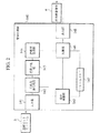
図6に、本実施形態に係る動画像符号化伝送システムで用いられる符号化装置20を示す。本実施形態に係る符号化装置20は、動画像(入力映像信号2)を第1の画像ブロック(マクロブロック)単位で符号化するものである。
【0097】
以下、主として、本実施形態に係る符号化装置20について、従来のH.263符号化方式に準拠した符号化装置120との相違点を説明することとする。そして、特に説明を行わない点については、本実施形態に係る符号化装置20は、H.263符号化方式に準拠した符号化装置120と同様であるものとする。
【0098】
符号化装置20は、従来の減算部124の代わりに混合予測部24が設けられており、従来の加算部131の代わりに混合予測復号部31が設けられている点で、従来の符号化装置120と構成を異にする。
【0099】
また、本実施形態に係る符号化装置20では、「マクロブロックモード」が、動き検出部22によってではなく、混合予測部24によって決定される。
【0100】
混合予測部24は、入力部21により送信された「マクロブロック(第1の画像ブロック)」を8×8画素の「サブブロック(第2の画像ブロック)」に分割する。
【0101】
また、混合予測部24は、「サブブロック」ごとに「予測残差信号電力を表す値」を算出する。例えば、混合予測部24は、「予測残差信号電力を表す値」として、入力部21により送信されたマクロブロック内のサブブロックと、動き補償部23により送信された予測画像ブロック内のサブブロックとの間の「SAD(Sums of Absolutes Differences:差分絶対値和)」を算出する。
【0102】
また、混合予測部24は、算出した「SAD」と所定の閾値とを比較して、「SAD」が閾値より小さい場合、当該サブブロックに「フレーム間予測モード(第1の予測モード)」を適用することを選択し、SADが閾値より大きい場合、当該サブブロックに「フレーム内予測モード(第2の予測モード)」を適用することを選択する。
【0103】
また、混合予測部24は、マクロブロック内の全てのサブブロックについて、「フレーム間予測モード(第1の予測モード)」を適用するか又は「フレーム内予測モード(第2の予測モード)」を適用するかの「予測モード」の選択が終了した後、当該マクロブロック全体の「予測モード」の選択状況を調べて、当該マクロブロックの「マクロブロックモード」を決定する。
【0104】
ここで、「マクロブロックモード」は、「INTRAモード」と「INTERモード」と「INTER4Vモード」と「INTRA/INTERモード」を含む。なお、「マクロブロックモード」には、量子化パラメータの変更の有無等の違いから、これらの他にもいくつかのモードが存在する。
【0105】
本実施形態では、「マクロブロックモード」が、サブブロックごとの「予測モード」の選択状況の違いに基づいて選択されている場合についてのみ説明するが、「マクロブロックモード」は、同様に、量子化パラメータの変更の有無等によって選択され得る。
【0106】
具体的には、混合予測部24は、マクロブロック内の全てのサブブロックについて「フレーム内予測モード」が選択されている場合、「マクロブロックモード」として「INTRAモード」を選択する。
【0107】
また、混合予測部24は、マクロブロック内の全てのサブブロックについて「フレーム間予測モード」が選択されている場合、「マクロブロックモード」として「INTERモード」又は「INTER4Vモード」を選択する。
【0108】
また、混合予測部24は、マクロブロック内で「フレーム内予測モード」及び「フレーム間予測モード」の両者が混在して選択されている場合、「マクロブロックモード」として「INTRA/INTERモード」を選択する。
【0109】
また、混合予測部24は、マクロブロックごとに決定された「マクロブロクモード」を、可変長符号化部27及び混合予測復号部31に送信する。
【0110】
さらに、混合予測部24は、「マクロブロックモード」として「INTRA/INTERモード」を選択した場合、サブブロックごとの「予測モード」の選択状況と、「フレーム間予測モード」が適用されているサブブロックの「動きベクトル」とを、可変長符号化部27及び混合予測復号部31に送信する。
【0111】
ここで、混合予測部24は、「INTRA/INTERモード」が選択された場合に、動きベクトルの符号化に必要な情報量の増加を抑えるため、1つのマクロブロックにつき1つの動きベクトルを可変長符号化部27及び混合予測復号部31に送信してもよい。
【0112】
また、混合予測部24は、動き検出部22によって検出された「INTERモード」用の動きベクトルをそのまま可変長符号化部27及び混合予測復号部31に送信してもよい。この結果、混合予測部24において再度の動きベクトルの計算が不要となり、処理量の増加を抑えることができる。
【0113】
また、混合予測部24は、動き検出部22によって検出された「INTER4Vモード」用の4つの動きベクトルのうち、最も多く現れた動きベクトルを当該マクロブロックの動きベクトルとして可変長符号化部27及び混合予測復号部31に送信してもよい。この結果、可変長符号化部27は、マクロブロック内で「フレーム間予測モード」により効率的に符号化処理が可能であるサブブロックに適した動きベクトルを選択することができるとともに、「INTRA/INTERモード」で符号化効率を高めることができる。
【0114】
また、混合予測部24は、「INTRA/INTERモード」が選択された場合に、動きベクトルを新たに探索して求めても良い。
【0115】
かかる場合、混合予測部24は、より効率的な符号化が可能となるように、「フレーム内予測モード」と組み合わせた場合に最もSADが低くなるような動きベクトルを探索する。
【0116】
すなわち、混合予測部24は、「INTERモード」のマクロブロックにおける予測画像ブロック内の個々のサブブロックにおいてSADを求め、最もSADが大きいサブブロックを外して再び動きベクトルの探索を行うことを繰り返すようなロバスト推定を用いた探索により実現できる。この結果、より最適に近い動きベクトルを探索することができる。
【0117】
上述のように、混合予測部24は、マクロブロック(第1の画像ブロック)を分割したサブブロック(第2の画像ブロック)単位で、時間方向の冗長度を削除する「フレーム間予測モード(第1の予測モード)」を適用するか、又は、空間方向の冗長度を削減する「フレーム内予測モード(第2の予測モード)」を適用するかを示す「予測モード選択状況(予測モード選択情報)」を生成する予測モード選択情報生成手段を構成する。
【0118】
また、混合予測部24は、選択された「フレーム間予測モード(第1の予測モード)」又は「フレーム内予測モード(第2の予測モード)」をサブブロック(第2の画像ブロック)に適用することにより予測残差信号を生成する予測残差信号生成手段を構成する。
【0119】
可変長符号化部27は、量子化部26により送信された「量子化直交変換係数」を可変長符号化するとともに、混合予測部24から送信された「マクロブロックモード」に基づいて、所定の情報、例えば、上述の予測モードの選択状況や動きベクトルを示す情報等を可変長符号化し、その結果を出力部28に送信する。
【0120】
ここで、「INTRA/INTERモード」を表現するために、H.263符号化方式におけるPピクチャのマクロブロックモードの定義を、図8(a)に示すように変更する。図8(a)において「MB type=6,7」である「マクロブロックモード」が、「INTRA/INTERモード」を表現するために拡張された部分である。
【0121】
可変長符号化部27は、かかるマクロブロックモードの定義を参照して、「量子化直交変換係数」と共に、どの情報(「COD」、「MCBPC」、「CBPY」、「DQUANT」、「MVD」、「MVD2-4」)を圧縮ビットストリーム3に多重化すべきかを決定することができる。
【0122】
図8(a)において、「COD」は、当該マクロブロックが「スキップ」であるか否かを示すフラグである。「スキップ」とは、当該マクロブロックは、フレームメモリ32内に格納されている参照フレーム内の同一空間位置の画像をそのままコピーすることで再現され、特別な情報追加の必要がないことを示すものである。「MB type=Not coded」の場合は「COD=1」であり、可変長符号化部27は、当該マクロブロックにおいて「COD」以外の情報を多重化しない。
【0123】
「MCBPC」は、当該マクロブロックモードにおいて、色差信号の「符号化ブロックパターン情報(coded block pattern:CBP)」を併せて表現するためのシンタックス要素である。ここで、「符号化ブロックパターン情報:CBP」とは、DCT変換の単位となるサブブロック内に伝送すべき有意なDCT係数が存在するか否かを示すフラグのことを意味する。
【0124】
「CBPY」は、当該マクロブロックモードにおいて、輝度信号の符号化ブロックパターン情報を併せて表現するためのシンタックス要素である。
【0125】
「DQUANT」は、当該マクロブロックの量子化パラメータ(例えば、量子化ステップ)の変更値を示すものである。
【0126】
「MVD」は、動きベクトルであり、「MVD2-4」は、「INTER4Vモード」の場合に伝送される2乃至4本目の動きベクトルである。
【0127】
「INTRA/INTERモード」では、サブブロックごとに「フレーム内予測モード」と「フレーム間予測モード」とを切り替えて符号化することを可能とするために、「COD=0」とし、DCT係数の分布状況に応じて「MCBPC」及び「CBPY」を決定し、「フレーム間予測モード」が適用されるサブブロックのために「MVD」を伝送するシンタックス(「MB type=6又は7」)が用いられる。
【0128】
また、各サブブロックにおける「フレーム内予測モード」と「フレーム間予測モード」の選択状況を示すために、H.263符号化方式における「ブロックレイヤ」のシンタックスを、図8(b)のように拡張する。
【0129】
図8(b)において、「BTYPE」は、1ビットで構成されており、「MB type=6,7」の場合にのみ存在するものである。ここで、「BTYPE=0」は、フレーム内予測モードにより符号化されたサブブロックであることを示し、「BTYPE=1」は、フレーム間予測モードにより符号化されたサブブロックであることを示す。
【0130】
「INTRADC」は、「MB type=6,7」の場合で、かつ、「BTYPE=0」の場合にのみ存在する。
【0131】
上述のように、可変長符号化部27及び出力部28が、サブブロック(第2の画像ブロック)ごとの予測モード選択状況(予測モード選択情報)及び予測残差信号を符号化して伝送する伝送手段を構成する。
【0132】
混合予測復号部31は、混合予測部24により送信された「マクロブロックモード」に基づいて、以降の符号化処理に用いる「参照フレーム」を構成する「マクロブロック」を生成し、生成したマクロブロックをフレームメモリ32に送信するものである。
【0133】
具体的には、混合予測復号部31は、「マクロブロックモード」として「INTRAモード」が選択されている場合、当該マクロブロックは「フレーム内予測」により構成されていることから、逆直交変換部30により送信された「予測残差信号」を「参照フレーム」を構成する「マクロブロック」とする。
【0134】
また、混合予測復号部31は、「マクロブロックモード」として「INTERモード」又は「INTER4Vモード」が選択されている場合、当該マクロブロックは「フレーム間予測」により構成されていることから、逆直交変換部30により送信された「予測残差信号」と動き補償部23により送信された「予測画像ブロック」とを加算することによって得られた結果を「参照フレーム」を構成する「マクロブロック」とする。
【0135】
また、混合予測復号部31は、「マクロブロックモード」として「INTRA/INTERモード」が選択されている場合、サブブロックごとに、「フレーム内予測モード」または「フレーム間予測モード」のどちらの予測モードが適用されているかを切り替える。
【0136】
ここで、混合予測復号部31は、「フレーム内予測モード」が適用されている場合には、逆直交変換部30により送信された「予測残差信号(サブブロック単位)」を「参照フレーム」を構成する「サブブロック」とする。
【0137】
一方、混合予測復号部31は、「フレーム間予測モード」が適用されている場合には、逆直交変換部30により送信された「予測残差信号(サブブロック単位)」と動き補償部23により送信された「予測画像ブロック(サブブロック単位)」とを加算することによって得られた結果を「参照フレーム」を構成する「サブブロック」とする。
【0138】
本実施形態に係る復号化装置40を図7に示す。以下、主として、本実施形態に係る復号化装置40について、従来のH.263符号化方式に準拠した復号化装置140との相違点を説明することとする。そして、特に説明を行わない点については、本実施形態に係る復号化装置40は、H.263符号化方式に準拠した復号化装置140と同様であるものとする。
【0139】
復号化装置40は、従来の加算部146の代わりに混合予測復号部46が設けられている点で、従来の符号化装置120と構成を異にする。
【0140】
可変長復号化部42は、入力部41により送信された圧縮ビットストリーム3において、各フレーム画像の先頭から、マクロブロックごとに必要な情報(「量子化直交変換係数」や「マクロブロックモード」や「動きベクトル」等)を復号化する。
【0141】
また、可変長復号化部42は、復号化した「量子化直交変換係数」を逆量子化部43に送信し、復号化した「マクロブロックモード」を混合予測復号部46に送信し、復号化した「動きベクトル」を動き補償部45に送信する。
【0142】
また、可変長復号化部42は、「INTRA/INTERモード」が選択された場合、サブブロックごとの「予測モードの選択状況」及び「動きベクトル」を、混合予測復号部46に送信する。
【0143】
上述のように、可変長復号化部42は、動画像を分割したマクロブロック(第1の画像ブロック)を分割したサブブロック(第2の画像ブロック)単位で、時間方向の冗長度を削除する「フレーム間予測モード(第1の予測モード)」を適用するか、又は、空間方向の冗長度を削減する「フレーム内予測モード(第2の予測モード)」を適用するかを示す「予測モード選択状況(予測モード選択情報)」を復号化する予測モード選択情報復号化手段を構成する。
【0144】
混合予測復号部46は、「マクロブロックモード」として「INTRAモード」が選択されている場合、当該マクロブロックは、フレーム内予測により構成されていることから、逆直交変換部44により送信された「予測残差信号」を、出力映像信号4を構成する「マクロブロック」とする。
【0145】
また、混合予測復号部46は、「マクロブロックモード」として「INTERモード」又は「INTER4Vモード」が選択されている場合、当該マクロブロックは、動き補償フレーム間予測により構成されていることから、逆直交変換部44により送信された「予測残差信号」と動き補償部45により送信された「予測画像ブロック」とを加算することによって得られた結果を、出力映像信号4を構成する「マクロブロック」とする。
【0146】
また、混合予測復号部46は、「マクロブロックモード」として「INTRA/INTERモード」が選択されている場合、可変長復号化部42から送信された「予測モードの選択状況」に基づいて、サブブロックごとに、「フレーム内予測モード」または「フレーム間予測モード」のどちらの予測モードが用いられるかを切り替える。
【0147】
ここで、混合予測復号部46は、サブブロックに「フレーム内予測モード」が適用されている場合には、逆直交変換部44により送信された「予測残差信号(サブブロック単位)」を、出力映像信号4を構成する「サブブロック」とする。
【0148】
一方、混合予測復号部46は、サブブロックに「フレーム間予測モード」が適用されている場合には、逆直交変換部44により送信された「予測残差信号(サブブロック単位)」と動き補償部45により送信された「予測画像ブロック(サブブロック単位)」とを加算することによって得られた結果を、出力映像信号4を構成する「サブブロック」とする。
【0149】
さらに、混合予測復号部46は、上述のようにして得られた「サブブロック」によって構成される「マクロブロック」を、出力部48に送信するとともに、以降の符号化処理に用いる「参照フレーム」を構成する「マクロブロック」としてフレームメモリ47に送信する。
【0150】
上述のように、混合予測復号部46は、予測モード選択状況(予測モード選択情報)により選択された「フレーム間予測モード(第1の予測モード)」又は「フレーム内予測モード(第2の予測モード)」に基づいて、サブブロック(第2の画像ブロック)単位で、出力映像信号(動画像)4を復号化する動画像復号化手段を構成する。
【0151】
(実施形態1に係る動画像符号化伝送システムの動作)
上記構成を有する動画像符号化伝送システムの動作について、図9を参照にして説明する。図9は、符号化装置20の混合予測部24の処理を示すフローチャート図である。以下、符号化装置20の混合予測部24の動作を主として、動画像符号化伝送システムの動作について説明する。
【0152】
混合予測部24は、図9に示すように、ステップ401において、入力部21により送信されたマクロブロックを、8×8画素のサブブロックごとに分割する。
【0153】
ステップ402において、混合予測部24は、サブブロックごとに、入力部21により送信されたマクロブロック内のサブブロックと、動き補償部23により送信された予測画像ブロック内のサブブロックとの間の「SAD」を算出する。
【0154】
ステップ403において、混合予測部24は、算出したSADと所定の閾値とを比較する。
【0155】
SADが閾値より大きい場合、ステップ404において、混合予測部24は、当該サブブロックに「フレーム内予測モード」を適用することを選択する。
【0156】
一方、SADが閾値より大きくない場合、ステップ405において、混合予測部24は、当該サブブロックに「フレーム間予測モード」を適用することを選択する。
【0157】
ステップ406において、混合予測部24は、当該マクロブロック内の全てのサブブロックで、上述の予測モードの選択が行われた否か判断し、行われていない場合は、ステップ402に戻り、残りのサブブロックについて上述の予測モードの選択を行う。
【0158】
全てのサブブロックで上述の選択が行われた場合、混合予測部24は、ステップ407において、当該マクロブロック全体の予測モードの選択状況を調べて、全てのサブブロックについて「フレーム内予測モード」が選択されているか否か判断する。
【0159】
肯定的(YES)である場合、すなわち、全てのサブブロックについて「フレーム内予測モード」が選択されている場合、ステップ408において、混合予測部24は、当該マクロブロックの「マクロブロックモード」を「INTRAモード」と設定する。
【0160】
一方、否定的(NO)である場合、すなわち、全てのサブブロックについて「フレーム内予測モード」が選択されていない場合、混合予測部24は、ステップ409において、当該マクロブロック全体の予測モードの選択状況を調べて、全てのサブブロックについて「フレーム間予測モード」が選択されているか否か判断する。
【0161】
肯定的(YES)である場合、すなわち、全てのサブブロックについて「フレーム間予測モード」が選択されている場合、ステップ410において、混合予測部24は、当該マクロブロックの「マクロブロックモード」を「INTERモード」または「INTER4Vモード」と設定する。
【0162】
ここで、「INTERモード」か「INTER4Vモード」かどちらとするかは、マクロブロック内で動きベクトルの違いがあるかないかに基づき決定される。
【0163】
一方、否定的(NO)である場合、すなわち、全てのサブブロックについて「フレーム間予測モード」が選択されていない場合、混合予測部24は、ステップ411において、当該マクロブロックの「マクロブロックモード」を「INTRA/INTERモード」と設定する。
【0164】
ステップ412において、混合予測部24は、マクロブロックごとに決定された「マクロブロックモード」を、可変長符号化部27及び混合予測復号部31に送信する。
【0165】
ただし、混合予測部24は「マクロブロックモード」として「INTRA/INTERモード」を設定した場合、「マクロブロックモード」と、各サブブロックの「予測モードの選択状況」と、各サブブロック(フレーム間予測モードが適用されるサブブロック)の「動きベクトル」とを、可変長符号化部27及び混合予測復号部31に送信する。
【0166】
本実施形態に係る動画像符号化伝送システムは、ITU-T H.263に準拠した構成として説明したが、本発明は、これに限られるものではなく、「フレーム間予測モード(第1の予測モード)」及び「フレーム内予測モード(第2の予測モード)」の予測モードを用い、かつマクロブロック(第1の画像ブロック)相当の単位で符号化が行われるような様々な動画像符号化伝送システムに適用可能である。
【0167】
また、「INTRA/INTERモード」についても、本実施形態で示した構成に限られるものでなく、マクロブロック(第1の画像ブロック)内の各サブブロック(第2の画像ブロック)において「フレーム間予測モード」及び「フレーム内予測モード」のどちらが適用されるかを示す様々なシンタックスを用いることができる。
【0168】
同様に「BTYPE」についても、本実施形態で示した構成に限られるものでなく、各サブブロックにおいて「フレーム間予測モード」及び「フレーム内予測モード」のどちらが適用されるかを示すことができる様々なシンタックスを用いることができる。
【0169】
また、本実施形態において、混合予測部24は、算出したSADと所定の閾値とを比較して、「マクロブロックモード」を選択することとしているが、この選択基準は、本実施形態で示した構成に限られるものではない。
【0170】
例えば、それぞれの「マクロブロックモード」によって当該マクロブロックにおける圧縮ビットストリーム3を実際に構成してみて、そのビット量が小さくなる方の「マクロブロックモード」を選択する等、より効率的な符号化を可能とする「マクロブロックモード」を選択するための様々な選択基準を用いることができる。
【0171】
(実施形態1に係る動画像符号化伝送システムの作用・効果)
実施形態1に係る動画像符号化伝送システムによれば、混合予測部24が、サブブロックから空間方向の冗長度又は時間方向の冗長度を削減した予測残差信号を最適に生成することができるため、1つのマクロブロック内に、フレーム間予測モードで符号化処理したほうが良い部分と、フレーム内予測モードで符号化処理したほうが良い部分とが混在している場合であっても、効率の良い符号化処理を行うことができる。
【0172】
(本発明の実施形態2に係る動画像符号化伝送システムの構成)
本発明の実施形態2に係る動画像符号化伝送システムの構成について図10及び図11を参照しながら説明する。図10は、本実施形態に係る動画像符号化伝送システムで用いられる符号化装置60を示す図であり、図11は、本実施形態に係る動画像符号化伝送システムで用いられる復号化装置80を示す図である。
【0173】
本実施形態に係る動画像符号化伝送システムは、ITU-T H.26L符号化方式に準拠し、その上で本発明の実施に必要な変更が加えられた構成を有する。H.26L符号化方式は、「ITU-T SG16 Q.6 VCEG-M81, “H.26 Test Model Long Term Number7(TML-7) draft0.”」等に記載されている。
【0174】
本実施形態に係る動画像符号化伝送システムは、上述の実施形態1に係る動画像符号化伝送システムと比較すると、「サブブロック」単位の微小化、動きベクトル検出方法の多様化、ループフィルタ73及び空間予測部74の採用という点で変更されている。
【0175】
第1に、符号化装置60において、上述の「サブブロック」単位の微小化に係る相違点について説明する。本実施形態において、直交変換の対象となる「サブブロック」単位は、上述の実施形態に係る符号化装置20の場合の「8×8画素」よりも小さい「4×4画素」となっている。したがって、予測モード選択の最小単位及び動きベクトルの検出の最小単位も、「4×4画素」のサブブロックとなっている。
【0176】
第2に、符号化装置60において、上述の動きベクトル検出方法の多様化に係る相違点について説明する。
【0177】
動き検出部62は、4×4画素のサブブロックを最小単位として、「動きベクトル」の検出を行う。
【0178】
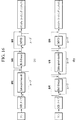
具体的には、動き検出部62は、フレームメモリ72に格納されている参照フレームを用いて、入力部61を介して受信したサブブロックについて、図12に示す7種類の動き検出単位(16×16、16×8、8×16、8×8、4×8、8×4、4×4)の全てに係る動きベクトルの検出を行う。
【0179】
また、動き検出部62は、検出した動きベクトルと当該動きベクトルの検出に用いられた動き検出単位とを、動き補償部63に送信する。
【0180】
動き補償部63は、受信した動きベクトルの各々とフレームメモリ72に格納されている参照フレームとを用いて「予測画像ブロック」を生成する。また、動き補償部63は、生成した予測画像ブロックと当該予測画像ブロックに対応する動き検出単位とを混合予測部64に送信する。
【0181】
第3に、符号化装置60において、上述の空間予測部74の採用に係る相違点について説明する。
【0182】
空間予測部74は、図13に示すように、入力部61により送信されたマクロブロック内のサブブロック(4×4画素)ごとに、当該サブブロックに隣接したサブブロックの画素値を用いた数種類の画素値予測方法でフレーム内画素値予測を行い、予測画像ブロックを生成する。
【0183】
ここで、空間予測部74は、上述のフレーム内画素値予測を行うにあたって、上述の隣接したサブブロックとして、直交変換と量子化と逆量子化と逆直交変換とに至る一連の処理を行ったサブブロックを必要とする。したがって、本実施形態では、直交変換と量子化と逆量子化と逆直交変換とに至る一連の処理を、4×4画素のサブブロック単位で行う。
【0184】
また、空間予測部74は、上述の一連の処理を行ったサブブロック(4×4画素)を用いて上述のフレーム内画素値予測を行う。
【0185】
また、空間予測部74は、生成した予測画像ブロックと当該予測画像ブロックに対応する画素値予測方法とを、混合予測部64及び混合予測復号部71に送信する。
【0186】
混合予測部64は、入力部61により送信されたマクロブロック内のサブブロックと動き補償部63により生成された「予測画像ブロック(サブブロック単位)」との間のSADが最も低くなる「予測画像ブロック(サブブロック単位)」に対応する動き検出単位を選択する。ここで、混合予測部64は、当該サブブロックに対して、上述の動き検出単位に対応する「フレーム間予測モード」を適用する。
【0187】
また、混合予測部64は、入力部61により送信されたマクロブロック内のサブブロックと空間予測部74により生成された「予測画像ブロック(サブブロック単位)」との間のSADが最も低くなる「予測画像ブロック(サブブロック単位)」に対応する画素値予測方法を選択する。当該サブブロックに対して、上述の画素値予測方法に対応する「フレーム内予測モード」を適用する。
【0188】
ここで、混合予測部64は、「フレーム間予測モード」が適用された場合の第1のSADと「フレーム内画素値予測モード」が適用された場合の第2のSADとを比較して、SADが小さい方の「予測モード」を当該サブブロックに適用することとする。
【0189】
また、混合予測部64は、マクロブロック内の全てのサブブロックに対して、例えば、左上のブロックから順に右下のブロックまで、上述のように「予測モード」を適用する。
【0190】
なお、上述のように、混合予測部64が、マクロブロック内の全てのサブブロックに対して、上述の動き検出単位に対応する「フレーム間予測モード」又は上述の画素値予測方法に対応する「フレーム内予測モード」を適用した場合の「マクロブロックモード」を「INTRA/INTERモード」とする。
【0191】
また、混合予測部64は、マクロブロックにおいて「INTRA/INTERモード」又は「INTERモード」又は「INTRAモード」が適用された場合のSAD(入力部61により送信されたマクロブロックとの間のSAD)を比較して、SADが最も小さくなった「マクロブロックモード」を、当該マクロブロックの「マクロブロックモード」として、可変長符号下部67に送信する。
【0192】
この結果、混合予測部64は、サブブロックごとに「フレーム間予測モード」又は「フレーム内画素値予測モード」を適用して、最も符号化効率が良くなる組み合わせを探索することができる。
【0193】
「マクロブロックモード」として「INTRA/INTERモード」が選択された場合、混合予測部64は、「マクロブロックモード」と、各サブブロックにおける「予測モードの選択状況」と、各サブブロックにおける「動きベクトル」又は「画素値予測方法」とを、可変長符号化部67及び混合予測復号部71に送信する。
【0194】
混合予測復号部71は、「マクロブロックモード」として「INTRA/INTERモード」が選択されている場合で、かつ、当該サブブロックに「フレーム内画素値予測モード」が選択されている場合、空間予測部74により送信された予測画像ブロックと逆直交変換部70から送信された予測残差信号とを加え、その結果をループフィルタ73に送信する。
【0195】
また、混合予測復号部71は、「マクロブロックモード」として「INTRA/INTERモード」が選択されている場合で、かつ、当該サブブロックに「フレーム間予測モード」が選択されている場合、動き補償部63により送信された予測画像ブロックと逆直交変換部70から送信された予測残差信号とを加え、その結果をループフィルタ73を経由してフレームメモリ72に送信する。
【0196】
第4に、符号化装置60において、上述のループフィルタ73の採用に係る相違点について説明する。
【0197】
ループフィルタ73は、混合予測復号部71により送信された結果に対して、サブブロック単位でフィルタリング処理を行い、サブブロックの歪み等の劣化を抑える働きをするものである。
【0198】
また、本実施形態に係る動画像符号化伝送システムにおいて、「INTRA/INTERモード」である「マクロブロックモード」を示すために、H.26L符号化方式におけるPピクチャのマクロブロックモードの定義を、図14(a)に示すように変更する。
【0199】
図14(a)において「Intra_pred_mode」は、「フレーム内画素値予測モード」が適用されたサブブロックにおいて用いられる画素値予測方法を示すものである。
【0200】
また、「Ref_frame」は、「フレーム間予測モード」が適用されたサブブロックにおいて用いられる動き検出単位を示すものである。
【0201】
また、各サブブロックにおける「予測モードの選択状況」を表現するために、「Intra_pred_mode」を、図14(b)のように拡張する。「INTER_PRED:6」の部分が、拡張された部分である。
【0202】
本実施形態においては、図14(a)に示すように、従来のH.26L符号化方式において定義されている「INTRA4×4モード」に相当するマクロブロックモードを「INTRA/INTERモード」に変更する。
【0203】
従来のH.26L符号化方式では、マクロブロックモードとして「INTRA4×4モード」が選択されている場合に、「MB type=7」が割り当てられている。
【0204】
一方、本実施形態に係る「INTRA/INTERモード」は、図14(b)に示すように、「MB type=7」が割り当てられているマクロブロックモードにおいて、「Intra_pred_mode」に「INTER_PRED」を1つ追加し、4×4画素のサブブロック単位で、フレーム内画素値予測モードだけでなく、フレーム間予測モードも選択できるように定義した。
【0205】
「INTRA/INTERモード」の定義は、上述の方法に限られず、「INTRA4×4モード」とは別に行われてもよい。例えば、「INTRA/INTERモード」の定義は、サブブロックごとの予測モードの選択状況に応じて、別々のマクロブロックモードを割り当てることによって行われてもよい。
【0206】
この結果、「Intra_pred_mode」によって、マクロブロック内のフレーム内予測モードが適用されたサブブロックの数やフレーム間予測モードが適用されたサブブロックの数を判別することができる。
【0207】
また、符号化装置60は、「INTRA/INTERモード」が適用されたマクロブロックにおいて、「Intra_pred_mode」を、「MV」や「Ref_frame」等のフレーム間予測モードに係る情報よりも先に送信することによって、かかるフレーム間予測に関する情報が必要ない場合において、「INTRA/INTERモード」用のシンタックス要素を無駄なく送信することができる。
【0208】
また、混合予測部64は、「INTRA/INTERモード」が選択された場合に、動きベクトルの符号化に必要な情報量の増加を抑えるため、1つのマクロブロックにつき1つの動きベクトルを可変長符号化部67及び混合予測復号部71に送信してもよい。
【0209】
また、混合予測部64は、現マクロブロックに隣接するマクロブロックのうち、既に符号化済みのマクロブロック(INTERモード)の動きベクトルから予測値を求め、当該予測値との差分を現マクロブロックの動きベクトルとしてもよい。
【0210】
また、混合予測部64は、事前に動き検出部62によって検出された「INTER16×16モード」用の動きベクトルをそのまま可変長符号化部67及び混合予測復号部71に送信してもよい。
【0211】
また、混合予測部64は、動き検出部62によってサブブロック単位で検出された動きベクトルのうち、最も多く現れた動きベクトルを現マクロブロックの動きベクトルとして可変長符号化部67及び混合予測復号部71に送信してもよい。
【0212】
この結果、マクロブロック内で「フレーム間予測モード」により効率的に符号化処理が可能であるサブブロックに適した動きベクトルを選択することができ、「INTRA/INTERモード」で符号化効率を高めることができる。
【0213】
本実施形態に係る復号化装置80を図11に示す。以下、主として、本実施形態に係る復号化装置80について、上述の実施形態1に係る復号化装置40との相違点を説明することとする。そして、特に説明を行わない点については、本実施形態に係る復号化装置80は、上述の実施形態1に係る復号化装置40と同様であるものとする。
【0214】
本実施形態に係る復号化装置80は、ループフィルタ89及び空間予測部90が設けられている点で、上述の実施形態1に係る復号化装置40と構成を異にする。
【0215】
ループフィルタ89は、符号化装置60のループフィルタ73と同一の機能を具備するものであり、混合予測復号部86により送信された結果に対して、サブブロック単位でフィルタリング処理を行い、サブブロックの歪み等の劣化を抑える働きをするものである。
【0216】
空間予測部90は、フレームメモリ72に格納されている参照フレームの画像内のサブブロック(4×4画素)ごとに、可変長復号化部82から送信された画素値予測方法で、フレーム内画素値予測を行い、予測画像ブロックを生成する。
【0217】
具体的には、混合予測復号部86は、「マクロブロックモード」として「INTERモード」が選択されている場合、当該マクロブロックは動き補償フレーム間予測により構成されていることから、逆直交変換部84により送信された「予測残差信号」と動き補償部85により送信された「予測画像ブロック」とを加算することによって得られた結果を、出力映像信号4を構成する「マクロブロック」とする。
【0218】
また、混合予測復号部86は、「マクロブロックモード」として「INTRAモード」が選択されている場合、当該マクロブロックは、フレーム内予測により構成されていることから、逆直交変換部84により送信された「予測残差信号」と空間予測部90により送信された「予測画像ブロック」とを加算することによって得られた結果を、出力映像信号4を構成する「マクロブロック」とする。
【0219】
また、混合予測復号部86は、「マクロブロックモード」として「INTRA/INTERモード」が選択されている場合、4×4画素のサブブロックごとに、「フレーム内予測モード」または「フレーム間予測モード」のどちらの予測モードが用いられるかを切り替える。
【0220】
すなわち、混合予測復号部86は、当該サブブロックに「フレーム内画素値予測モード」が適用されている場合には、逆直交変換部44により送信された「予測残差信号(サブブロック単位)」を、出力映像信号4を構成する「サブブロック」とする。
【0221】
一方、混合予測復号部86は、当該サブブロックに「フレーム内予測モード」が適用されている場合には、逆直交変換部44により送信された「予測残差信号(サブブロック単位)」と空間予測部90により送信された「予測画像ブロック」とを加算することによって得られた結果を、出力映像信号4を構成する「サブブロック」とする。
【0222】
混合予測復号部86は、これらの「サブブロック」により、出力映像信号4を構成する「マクロブロック」を生成する。
【0223】
また、可変長復号化部82は、第1又は第2の予測モードを行うために必要な予測モード関連情報(動きベクトルや画素値予測方法)を復号化する予測モード関連情報復号化手段を構成する。
【0224】
(実施形態2に係る動画像符号化伝送システムの動作)
上記構成を有する動画像符号化伝送システムの動作について、図15を参照にして説明する。図15は、符号化装置60の混合予測部64の処理を示すフローチャート図である。以下、符号化装置60の混合予測部64の動作を主として、動画像符号化伝送システムの動作について説明する。
【0225】
図15に示すように、混合予測部64は、ステップ901において、入力部61により送信されたマクロブロックを、4×4画素のサブブロックごとに分割する。
【0226】
ステップ902において、混合予測部64は、複数の動き検出単位を用いた動き補償フレーム間予測によって生成された複数の予測画像ブロック(サブブロック単位)を動き補償部63から受信し、複数の画素値予測方法を用いたフレーム内画素値予測によって生成された複数の予測画像ブロック(サブブロック単位)を空間予測部74から受信する。
【0227】
ステップ903において、混合予測部64は、動き補償部63からの複数の予測画像ブロック(サブブロック単位)の中から、入力部61により送信されたマクロブロック内のサブブロックとの間の第1のSADが最も低くなる予測画像ブロックを選択する。
【0228】
また、混合予測部64は、空間予測部74からの複数の予測画像ブロック(サブブロック単位)の中から、入力部61により送信されたマクロブロック内のサブブロックとの間の第2のSADが最も低くなる予測画像ブロックを選択する。
【0229】
ステップ904において、混合予測部64は、サブブロックごとに、上述の第1のSADと第2のSADとを比較し、第1のSADの方が小さい場合、ステップ905において、当該サブブロックの予測モードを「フレーム間予測モード」と設定し、第2のSADの方が小さい場合、ステップ906において、当該サブブロックの予測モードを「フレーム内画素値予測モード」と設定する。
【0230】
ステップ907において、混合予測部64は、当該マクロブロック内の全てのサブブロックで上述の選択が行われた否か判断し、行われていない場合は、ステップ902に戻り、残りのサブブロックについて上述の予測モードの選択を行う。
【0231】
全てのサブブロックで上述の予測モードの選択が行われた場合、混合予測部64は、ステップ908において、当該マクロブロック全体におけるSADの合計値である「INTRA/INTERモード」におけるSADと、動き補償部63により送信された動き補償フレーム間予測による予測画像ブロックのSADと、空間予測部74により送信されたフレーム内画素値予測による予測画像ブロックのSADとを比較する。
【0232】
そして、混合予測部64は、SADが最も低くなった予測モードを、当該マクロブロックの「マクロブロックモード」として適用する。
【0233】
ステップ909において、混合予測部64は、この「マクロブロックモード」を、可変長符号化部67と混合予測復号部71とに送信する。
【0234】
ここで、「マクロブロックモード」として「INTRA/INTERモード」が選択された場合、混合予測部64は、「マクロブロックモード」と、各サブブロックにおける「予測モードの選択状況」と、「動きベクトル」又は「画素値予測方法」とを、可変長符号化部67と混合予測復号部71とに送信する。
【0235】
本実施形態に係る動画像符号化伝送システムは、ITU-T H.26Lに準拠した構成として説明したが、本発明は、これに限られるものではなく、「フレーム間予測モード(第1の予測モード)」及び「フレーム内予測モード(第2の予測モード)」の予測モードを用い、かつマクロブロック(第1の画像ブロック)相当の単位で符号化が行われるような様々な動画像符号化伝送システムに適用可能である。
【0236】
また、「INTRA/INTERモード」についても、本実施形態で示した構成に限られるものでなく、マクロブロック(第1の画像ブロック)内の各サブブロック(第2の画像ブロック)において「フレーム間予測モード」及び「フレーム内予測モード」のどちらが適用されるかを示す様々なシンタックスを用いることができる。
【0237】
例えば、「INTRA4×4モード」とは別に新たに「INTRA/INTERモード」を用いるようにしてもよい。この場合、マクロブロック内の各サブブロックの予測モード選択状況が、全て「フレーム内画素値予測モード」であった場合には、当該マクロブロックに「INTRA4×4モード」を適用する。一方、マクロブロック内の各サブブロックの予測モード選択状況が、「フレーム間予測モード」を含む場合には、当該マクロブロックに「INTRA/INTERモード」を適用する。
【0238】
この際、「INTRA4×4モード」においては、予測モード選択状況を示す「Intra_pred_mode」を、従来のH.26L符号化方式で用いられている拡張無しテーブルとする。一方、「INTRA/INTERモード」においては、予測モード選択状況を示す「Intra_pred_mode」を、図14(b)に示すような拡張を行ったテーブルや、「INTER_PRED」以外の「フレーム内予測モード」に係る項目を一部省略したテーブルとする。その結果、「INTRA4×4モード」及び「INTRA/INTERモード」用のシンタックス要素を効率的に送信することができる。
【0239】
同様に「Intra_pred_mode」についても、本実施形態で示した構成に限られるものでなく、各サブブロックにおいて「フレーム間予測モード」及び「フレーム内予測モード」のどちらが適用されるかを示すことができる様々なシンタックスを用いることができる。
【0240】
また、本実施形態において、混合予測部64は、算出したSADと所定の閾値とを比較して、「マクロブロックモード」を選択することとしているが、この選択基準は、本実施形態で示した構成に限られるものではない。
【0241】
例えば、それぞれの「マクロブロックモード」によって当該マクロブロックにおける圧縮ビットストリーム3を実際に構成してみて、そのビット量が小さくなる方の「マクロブロックモード」を選択する等、より効率的な符号化を可能とする「マクロブロックモード」を選択するための様々な選択基準を用いることができる。
【0242】
(実施形態2に係る動画像符号化伝送システムの作用・効果)
実施形態2に係る動画像符号化伝送システムによれば、混合予測部64が、サブブロックから空間方向の冗長度又は時間方向の冗長度を削減した予測残差信号を最適に生成することができるため、1つのマクロブロック内に、フレーム間予測モードで符号化処理したほうが良い部分と、フレーム内予測モードで符号化処理したほうが良い部分とが混在している場合であっても、効率の良い符号化処理を行うことができる。
【0243】
(本発明の実施形態3に係る動画像符号化伝送システムの構成)
本発明の実施形態3に係る動画像符号化伝送システムの構成について図を参照しながら説明する。本実施形態に係る動画像符号化伝送システムは、本発明の実施形態2の場合と同様に、ITU−T H.26L符号化方式に準拠し、その上で、本発明の実施に必要な変更が加えられた構成を具備するものである。本実施形態に係る動画像符号化伝送システムの構成は、実施形態2の場合と同じく、図10及び図11により示される。
【0244】
本実施形態に係る動画像符号化伝送システムは、実施形態2に係る動画像符号化伝送システムと比較すると、以下の点について変更されている。
【0245】
第1に、本実施形態に係る動画像符号化伝送システムは、「予測モード」として「フレーム間予測モード」を適用するか又は「フレーム内予測モード」を適用するかを選択する単位である「サブブロック」を、直交変換の単位である「4×4画素のブロック単位」ではなく、図12に示す「動き検出単位」としている点で変更されている。
【0246】
第2に、本実施形態に係る動画像符号化伝送システムは、かかるサブブロック単位で、「フレーム間予測モード」または「フレーム内予測モード」の適用を選択するために必要なシンタックスを定義している点で変更されている。
【0247】
以下、本実施形態に係る符号化装置60において、上述の実施形態2に係る符号化装置60と相違する点についてのみ説明することとし、特に説明を行わない点については、上述の実施形態2に係る符号化装置60と同様であるものとする。
【0248】
また、上記の「サブブロック」の単位の違いから、本実施形態の説明においては、実施形態2の場合とは異なり、直交変換の単位である4×4画素のブロックを、「サブブロック」ではなく「直交変換ブロック」と呼ぶこととする。
【0249】
本実施形態に係る符号化装置60において、動き検出部62は、図12に示す7種類の動き検出単位(16×16、16×8、8×16、8×8、4×8、8×4、4×4)、すなわち、「サブブロック」単位で、「動きベクトル」の検出を、それぞれの「予測モード(すなわち、図12に示す動き検出単位に対応)」における「動きベクトル」として、動き補償部63に送信する。
【0250】
動き補償部63は、動き検出部62により送信された「動きベクトル」をフレームメモリ72に格納されている参照フレームに適用して「予測画像ブロック(サブブロック単位)」を生成して混合予測部64に送信する。
【0251】
空間予測部74は、図11に示すように、入力部61により送信されたマクロブロック内の「直交変換ブロック(4×4画素)」ごとに、当該直交変換ブロックに隣接した直交変換ブロックの画素値を用いた数種類の画素値予測方法によってフレーム内画素値予測を行い、予測画像ブロック(サブブロック単位)を生成して混合予測部64に送信する。
【0252】
空間予測部74は、1つのサブブロックに含まれる全ての直交変換ブロックについて、上述の予測画像ブロックの生成を行い、入力部61を介して受信したサブブロックとのSADが最も小さくなるように、画素値予測方法を選択する。
【0253】
ここで、空間予測部74は、マクロブロック全体(16×16画素)についても、当該マクロブロックに隣接したマクロブロックの画素値を用いた数種類の画素値予測方法で、フレーム内画素値予測を行い、予測画像ブロックを生成する。
【0254】
空間予測部74は、混合予測部64に、上述の選択された画素値予測方法を用いて生成された予測画像ブロック(サブブロック単位)を送信する代わりに、上述の画素値予測方法を示す識別情報を送信してよい。
【0255】
上述の直交変換ブロックに隣接した直交変換ブロックは、直交変換と量子化と逆量子化と逆直交変換とに至る一連の処理を行ったものである必要があるため、空間予測部74は、かかる一連の処理済みの直交変換ブロックを用いて、上述のフレーム内画素値予測を行う。
【0256】
かかる場合、隣接する直交変換ブロックが、同じマクロブロック内に含まれる場合には、隣接する直交変換ブロックに用いられる予測モードが確定していない場合がある。
【0257】
かかる場合には、当該隣接する直交変換ブロックについて候補となっている予測モードを用いて、上述の符号化及び復号化処理が行われるものとしてもよい。あるいは、隣接する直交変換ブロックが、同じマクロブロック内に含まれる場合には、当該隣接する直交変換ブロックがマクロブロック外であるものとして、フレーム内画素値予測が行われるものとしてもよい。
【0258】
混合予測部64は、入力部61により送信されたマクロブロックを、「サブブロック(動き検出単位)」に分割し、サブブロック毎に「フレーム間予測モード」又は「フレーム内予測モード」を適用して、最も符号化効率が良くなる組み合わせを探索する。
【0259】
具体的には、混合予測部64は、以下のように、図12に示す7種類の動き検出単位に対応する「予測モード」を順に検査していく。
【0260】
混合予測部64は、それぞれの予測モードにおける各サブブロックについて、動き補償部63により送信された動き補償フレーム間予測による「予測画像ブロック(サブブロック単位)」及び空間予測部74により送信されたフレーム内画素値予測による「予測画像ブロック(直交変換ブロック単位)」のSAD(入力部61により送信されたマクロブロック内のサブブロックとの間のSAD)を算出し、SADが小さい方の予測手法(動き補償フレーム間予測又はフレーム内画素値予測)を当該サブブロックの予測手法とする。
【0261】
この予測手法による予測画像サブブロックに基づいて生成される「予測残差信号(サブブロック単位)」に対して、直交変換と量子化と逆量子化と逆直交変換とに至る一連の符号化及び復号化処理がなされる。マクロブロック内の(左上のサブブロックから順に右下のサブブロックまで)全てのサブブロックについて上述の処理が行われる。
【0262】
混合予測部64は、マクロブロック内の全てのサブブロックについて上述の処理を行った後、当該マクロブロック全体におけるSADの合計値を、それぞれの動き検出単位に対応する「マクロブロックモード(INTER 16×16モード等)」におけるSADとして保持する。そして、混合予測部64は、まだ検査の行われていない動き検出単位に対応する「マクロブロックモード(INTER 16×16モード等)」について、上述の処理を同様に行う。
【0263】
混合予測部64は、全ての動き検出単位に対応する「マクロブロックモード」について上述の処理を行った後、保持しておいたそれぞれの「マクロブロックモード」についてのSADを比較する。
【0264】
そして、混合予測部64は、SADが最も低くなった「マクロブロックモード」を、当該マクロブロックのフレーム間予測を用いた「マクロブロックモード(INTER 16×16等)」とし、そのSADを保持する。
【0265】
そして、混合予測部64は、動き補償フレーム間予測を行った場合の第1のSADを、空間予測部74により送信された当該マクロブロック全体についてフレーム内画素値予測を行った場合の第2のSADとを比較する。
【0266】
混合予測部64は、最終的にSADが最も低くなったマクロブロックモードを、当該マクロブロックの「マクロブロックモード」とし、この「マクロブロックモード」を、可変長符号化部67と混合予測復号部71とに送信する。
【0267】
「マクロブロックモード」として「INTERモード」が選択された場合、混合予測部64は、「マクロブロックモード」と、各サブブロックにおける「予測モードの選択状況」と、「動きベクトル」又は「画素値予測方法」とを、可変長符号化部67と混合予測復号部71とに送信する。
【0268】
混合予測復号部71は、「マクロブロックモード」として「INTERモード」が選択されている場合で、かつ、当該サブブロックに「フレーム間予測モード」が選択されている場合、動き補償部63により送信された「予測画像ブロック(サブブロック単位)」と「予測残差信号(サブブロック単位)」とを加え、その結果をループフィルタ73に送信する。
【0269】
また、混合予測復号部71は、「マクロブロックモード」として「INTERモード」が選択されている場合で、かつ、当該サブブロックに「フレーム内画素値予測モード」が選択されている場合、空間予測部74により送信された「予測画像ブロック(サブブロック単位)」と「予測残差信号(サブブロック単位)」に加え、その結果をループフィルタ73を経由してフレームメモリ72に送信する。
【0270】
ループフィルタ73は、混合予測復号部71により送信された結果に対して、サブブロック単位でフィルタリング処理を行い、サブブロックの歪み等の劣化を抑える働きをするものである。
【0271】
本実施形態に係る動画像符号化伝送システムにおいて、マクロブロック内にて「フレーム間予測モード」と「フレーム内画素値予測モード」とを混在させるために、「INTERモード」のシンタックスを以下のように拡張する。
【0272】
具体的には、本実施形態に係る動画像符号化伝送システムにおいて、「マクロブロックモード」として「INTERモード」が選択されている場合に、当該サブブロックにおける「フレーム間予測モード」と「フレーム内画素値予測モード」の選択状況を示すために、H.26L符号化方式におけるPピクチャのマクロブロックモードにおける「Ref_frame」及びシンタックスの定義を、図16及び図17に示すように拡張する。
【0273】
図16(a)に、従来のH.26LのPピクチャのマクロブロックモードにおけるシンタックスを示す。図16(a)において、「Intra_pred_mode」は、従来のH.26L符号化方式において「INTRA4×4モード」が選択された場合に、各直交変換ブロックにおいて選択された予測方法(動き補償フレーム間予測又はフレーム内画素値予測)を示すものである。
【0274】
「Ref_frame」は、H.26L符号化方式では、動き補償フレーム間予測で、複数の参照フレームを使用して「動きベクトル」を検出することができることから、マクロブロックにおいて、どの参照フレームを使用したかを示すものである。
【0275】
「MVD」は、動きベクトルの差分情報を示すものであり、「Texture Codin Syntax」は、上記以外の直交変換係数等の情報を示すものである。
【0276】
図16(a)に示すシンタックスを、図16(b)のように拡張する。「Ref_frame」は、「MB_type」により指示された「マクロブロックモード」により判別されるサブブロックの数だけ伝送されることとする。
【0277】
そのために拡張した「Ref_frame」の定義を、図17に示す。図17において、最大参照フレーム数を「5」として、「5」を示すコードの次のコードが、「フレーム内予測モード」を示すこととしている。
【0278】
H.26L符号化方式では、最大参照フレーム数は、可変であり、「5」以外の値も取ることができる。ここで、最大参照フレーム数は、符号化装置60及び復号化装置80において既知とされており、また、実際のアプリケーションにおいても、同様な設定情報は事前に伝送されると考えられる。
【0279】
したがって、「フレーム内予測モード」を示すコードには、最大参照フレーム数を示すコードの次のコードが割り当てられることとすれば、最大参照フレーム数にかかわらず、拡張した「Ref_frame」を符号化装置60と復号化装置80において一意に定義することができる。
【0280】
したがって、各サブブロックにおける「フレーム間予測モード」又は「フレーム内画素値予測モード」の選択状況は、「Ref_frame」を用いて伝送される。
【0281】
この結果、「INTERモード」が選択されたマクロブロックにおいて、「フレーム間予測モード」と「フレーム内画素値予測モード」を混在させることができる。
【0282】
また、「Ref_frame」により「フレーム間予測モード」又は「フレーム内予測モード」の選択状況が判別されることから、「Ref_frame」を「Intra_pred_mode」に先んじて伝送することとするとともに、「Intra_pred_mode」は、「Ref_frame」により「フレーム内予測モード」のサブブロックの存在が指示された場合に、「Ref_frame」により指示された「フレーム内予測モード」のサブブロックの数だけ伝送されることとする。
【0283】
「Ref_frame」を先に送信することによって、「MVD」等のフレーム間予測モードに関する情報や「Intra_pred_mode」等のフレーム内画素値予測モードに関する情報が必要ない場合でも、それぞれのシンタックス要素を無駄なく送信することができる。
【0284】
なお、この場合、従来のH.26L符号化方式の場合とは異なり、サブブロック毎に「Ref_frame」が伝送されることとなる。
【0285】
したがって、サブブロック毎に「フレーム間予測モード」と「フレーム内画素値予測モード」の選択が可能となるだけでなく、従来のH.26L符号化方式の場合にはマクロブロック毎に選択されていた参照フレームを、サブブロック毎に選択することが可能となる。
【0286】
本実施形態に係る復号化装置80の構成は、4×4画素のサブブロックを用いる代わりに、動き検出単位であるサブブロックを用いることを除いて、実施形態2に係る復号化装置80と同じである。
【0287】
(実施形態3に係る動画像符号化伝送システムの動作)
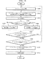
上記構成を有する動画像符号化伝送システムの動作について、図18を参照にして説明する。図18は、本実施形態における符号化装置60の混合予測部64の処理を示すフローチャート図である。以下、符号化装置60の混合予測部64の動作を主として、動画像符号化伝送システムの動作について説明する。
【0288】
混合予測部64は、図18に示すように、ステップ1501において、入力部61により送信されたマクロブロックを、サブブロック(動き検出単位に対応)ごとに分割する。
【0289】
ステップ1502において、混合予測部64は、動き補償部63からフレーム間予測を用いた予測画像ブロックを受信し、空間予測部74からフレーム内画素値予測を用いた予測画像ブロックを受信する。
【0290】
ステップ1503において、混合予測部64は、入力部61により送信されたマクロブロックとフレーム間予測を用いた予測画像ブロックとの間の第1のSAD、及び、入力部61により送信されたマクロブロックとフレーム内画素値予測を用いた予測画像ブロックとの間の第2のSADを算出する。
【0291】
ステップ1504において、混合予測部64は、サブブロックごとに、上述の第1のSADと第2のSADとを比較し、第1のSADの方が小さい場合、ステップ1505において、当該サブブロックの予測モードを「フレーム間予測モード」と設定し、第2のSADの方が小さい場合、ステップ1506において、当該サブブロックの予測モードを「フレーム内画素値予測モード」と設定する。
【0292】
ステップ1507において、混合予測部64は、当該マクロブロック内の全てのサブブロックで、予測モードの選択が行われた否か判断し、行われていない場合は、ステップ1502に戻り、残りのサブブロックについて、予測モードの選択を行う。
【0293】
全てのサブブロックで、予測モードの選択が行われた場合、混合予測部64は、ステップ1508において、当該マクロブロックについて、すべてのマクロブロックモード(INTER 16×16モード等)について、上述の選択が行われたか否か判断し、行われていない場合は、ステップ1501に戻り、残りのマクロブロックモードについて上述の予測モードの選択を行う。
【0294】
全てのサブブロックおよび全てのマクロブロックモードで、予測モードの選択が行われた場合、混合予測部64は、ステップ1509において、各マクロブロックモードに対して、当該マクロブロック全体におけるSADの合計値を比較する。
【0295】
また、混合予測部64は、空間予測部74によりマクロブロック全体(16×16画素)についてフレーム内画素値予測を行った場合(INTRAモード)のSADとも比較する。
【0296】
そして、混合予測部64は、SADが最も低くなった「マクロブロックモード」を、当該マクロブロックの「マクロブロックモード」として適用する。
【0297】
ステップ1510において、混合予測部64は、この「マクロブロックモード」を、可変長符号化部67と混合予測復号部71とに送信する。
【0298】
ここで、「マクロブロックモード」として「フレーム内予測モード」のサブブロックを含む「INTERモード」が選択された場合、混合予測部64は、「マクロブロックモード」と、各サブブロックにおける「予測モードの選択状況」と、「動きベクトル」又は「画素値予測方法」とを、可変長符号化部67と混合予測復号部71とに送信する。
【0299】
本実施形態に係る動画像符号化伝送システムは、ITU-T H.26Lに準拠した構成として説明したが、本発明は、これに限られるものではなく、「フレーム間予測モード(第1の予測モード)」及び「フレーム内予測モード(第2の予測モード)」の予測モードを用い、かつマクロブロック(第1の画像ブロック)相当の単位で符号化が行われるような様々な動画像符号化伝送システムに適用可能である。
【0300】
また、各サブブロックにおける「フレーム間予測モード」又は「フレーム内予測モード」の判別方法についても、本実施形態で示した構成に限られるものでなく、マクロブロック(第1の画像ブロック)内の各サブブロック(第2の画像ブロック)において「フレーム間予測モード」及び「フレーム内予測モード」のどちらが適用されるかを示す様々なシンタックスを用いることができる。
【0301】
各サブブロックにおける「フレーム間予測モード」又は「フレーム内予測モード」の判別方法については、本実施形態における「Ref_frame」のように、サブブロック単位で伝送される様々な情報に重畳して伝送することが考えられる。
【0302】
例えば、動きベクトル差分情報(MVD)を用いて、当該サブブロックが「フレーム内予測モード」である場合には、特別なベクトル値又は差分ベクトル値を用いて指示することもできる。
【0303】
また、サブブロック毎に伝送される新たな情報を定義して「Ref_frame」や「MVD」とは別に「フレーム間予測モード」や「フレーム内予測モード」の判別情報を伝送してもよい。
【0304】
また、「MVD」の符号化コードに特別なコード、すなわち、エスケープ符号を設定し、これが伝送された場合に「フレーム内予測モード」であることを指示することもできる。
【0305】
なお、本実施形態においては、マクロブロックモードとして「INTERモード」が選択された場合に、すべてのサブブロックにおいて「フレーム内予測モード」が選択される場合があり得る。
【0306】
かかる場合の符号化結果は、「画素値予測方法」等の情報が異なるため、必ずしもマクロブロックモードとして「INTRAモード」が選択された場合とは同じとはならない。
【0307】
したがって、このような「マクロブロックモード」の存在を許可することとしてもよい。
【0308】
しかしながら、この場合、予測方法(動き補償フレーム間予測又はフレーム内画素値予測)に変化のないフレーム内予測を用いたマクロブロックモードが複数存在することになる。
【0309】
このような事態を防ぐため、すべてのサブブロックが「フレーム内予測モード」となる「INTERモード」を禁止する、又はマクロブロックモードとしての「INTRAモード」を禁止するなどして、フレーム内予測を用いたマクロブロックモードが複数存在することを避けるようにしてもよい。
【0310】
(実施形態3に係る多重伝送装置の作用・効果)
実施形態3に係る動画像符号化伝送システムによれば、混合予測部64が、サブブロックから空間方向の冗長度又は時間方向の冗長度を削減した予測残差信号を最適に生成することができるため、1つのマクロブロック内に、フレーム間予測モードで符号化処理したほうが良い部分と、フレーム内予測モードで符号化処理したほうが良い部分とが混在している場合であっても、効率の良い符号化処理を行うことができる。
【0311】
(その他)
なお、上述の実施形態1乃至3に係る符号化装置20及び60、復号化装置40及び80の機能を、コンピュータ100に実行させるためのプログラムを、コンピュータ読み取り可能な記録媒体に記録することができる。このコンピュータ読み取り可能な記録媒体は、図19に示すように、例えば、フロッピィーディスク101、コンパクトディスク102、ICチップ103、カセットテープ104等が挙げられる。このようなプログラムを記録したコンピュータ読み取り可能な記録媒体によれば、プログラムの保存、運搬、販売等を容易に行うことができる。
【0312】
【発明の効果】
以上説明したように本発明によれば、マクロブロックの枠組みを変えることなく、1つのマクロブロック内で、予測モードの切り替えを行い、フレーム間予測モードで符号化処理する部分とフレーム内予測モードで符号化処理する部分とを混在させることができる。
【図面の簡単な説明】
【図1】 従来技術に係る動画像符号化伝送システムで用いられる符号化装置の構成を示す図である。
【図2】 従来技術に係る動画像符号化伝送システムで用いられる復号化装置の構成を示す図である。
【図3】 マクロブロックコードを示す図である。
【図4】 マクロブロック内で、フレーム内予測モードで符号化処理したほうが良い部分と、フレーム間予測モードで符号化処理したほうが良い部分とが混在しているケースを示す図である。
【図5】 本発明の一実施形態に係る動画像符号化伝送システムの概略構成図である。
【図6】 本発明の一実施形態に係る動画像符号化伝送システムで用いられる符号化装置の構成を示す図である。
【図7】 本発明の一実施形態に係る動画像符号化伝送システムで用いられる復号化装置の構成を示す図である。
【図8】 本発明の一実施形態に係る動画像符号化伝送システムで拡張されたマクロブロックモード及びブロックレイヤシンタックスの定義を示す表である。
【図9】 本発明の一実施形態に係る動画像符号化伝送システムで用いられる符号化装置の混合予測部の処理を示すフローチャート図である。
【図10】 本発明の一実施形態に係る動画像符号化伝送システムで用いられる符号化装置の構成を示す図である。
【図11】 本発明の一実施形態に係る動画像符号化伝送システムで用いられる復号化装置の構成を示す図である。
【図12】 本発明の一実施形態に係る動画像符号化伝送システムで用いられる符号化装置の動き検出部で用いられる動き検出ブロックを示す図である。
【図13】 本発明の一実施形態に係る動画像符号化伝送システムで用いられる符号化装置の空間予測部によって行われるフレーム内画素値予測の原理を示す図である。
【図14】 本発明の一実施形態に係る動画像符号化伝送システムで拡張されたマクロブロックモード及びブロックレイヤシンタックスの定義を示す表である。
【図15】 本発明の一実施形態に係る動画像符号化伝送システムで用いられる符号化装置の混合予測部の処理を示すフローチャート図である。
【図16】 従来技術及び本発明の一実施形態に係る動画像符号化伝送システムで用いられるマクロブロックシンタックスの定義を示す図である。
【図17】 本発明の一実施形態に係る動画像符号化伝送システムで拡張されたマクロブロックシンタックスの定義を示す表である。
【図18】 本発明の一実施形態に係る動画像符号化伝送システムで用いられる符号化装置の混合予測部の処理を示すフローチャート図である。
【図19】 本発明に係る動画像符号化伝送システムとして機能するプログラムを記録するコンピュータ読み取り可能な記録媒体を示す図である。[0001]
BACKGROUND OF THE INVENTION
The present invention relates to a moving image encoding / transmission system, a moving image encoding / transmitting method, an encoding device and a decoding device, an encoding method, a decoding method, and a program suitable for use in these.
[0002]
[Prior art]
One example of an encoding device and a decoding device used in a conventional moving image encoding transmission system will be described with reference to FIGS. FIG. 1 is a diagram illustrating a schematic configuration of an encoding device used in a conventional moving image encoding / transmission system, and FIG. 2 illustrates a schematic configuration of a decoding device used in a conventional moving image encoding / transmission system. FIG.
[0003]
1 and the
[0004]
The
[0005]
The
[0006]
The
[0007]
The
[0008]
The
[0009]
The
[0010]
The
[0011]
In addition, the
[0012]
As the “prediction mode”, an “interframe prediction mode” that reduces temporal redundancy is applied to the current macroblock, or an “intraframe prediction mode” that reduces spatial redundancy is applied. It is shown.
[0013]
Specifically, the
[0014]
The
[0015]
The
[0016]
For example, when the “macroblock mode” transmitted from the
[0017]
In addition, when the “macroblock mode” transmitted from the
[0018]
Here, in the “INTER mode”, one motion vector is assigned to a macro block of 16 × 16 pixels, and in the “INTER 4V mode”, one motion vector is assigned to a sub block of 8 × 8 pixels. ing.
[0019]
The
[0020]
The
[0021]
Specifically, when the “macroblock mode” is “INTER mode” or “INTER4V mode”, the
[0022]
Here, the difference obtained by the
[0023]
In addition, when the “macroblock mode” is “INTRA mode”, the “prediction image block” is not transmitted from the
[0024]
The
[0025]
The
[0026]
The
[0027]
The variable
[0028]
The
[0029]
The
[0030]
The inverse
[0031]
The
[0032]
However, when “INTRA mode” is selected as the “macroblock mode”, a “predictive image block” is not generated by the motion compensation unit 123 (no motion compensation inter-frame prediction is performed). The “prediction residual signal (the current macroblock transmitted by the input unit 121)” transmitted by the inverse
[0033]
The
[0034]
The
[0035]
The
[0036]
In the
[0037]
The variable
[0038]
The
[0039]
The inverse
[0040]
The
[0041]
The
[0042]
However, when the “macroblock mode” is the “INTRA mode”, the “prediction image block” is not transmitted by the
[0043]
The
[0044]
The
[0045]
As described above, in the conventional moving image coding and transmission system, “macroblock mode” is determined for each macroblock, and “encoding information (motion vector, quantization parameter, etc.)” set for each macroblock is set. The encoding efficiency is increased by performing the encoding process with the common use.
[0046]
[Problems to be solved by the invention]
However, in the conventional moving image coding and transmission system, a plurality of “macroblock modes” cannot be set for one macroblock. Therefore, as shown in FIG. Efficient coding is possible if there is a mix of a portion that should be encoded in the “prediction mode” (bird portion) and a portion that should be encoded in the “interframe prediction mode” (cloud portion). There was a problem that processing could not be performed.
[0047]
In order to solve this problem, a method of reducing the size of the macro block and making the unit for switching the selection of the “macro block mode” fine can be considered. However, this method has a problem in that the number of macroblocks increases and the frequency of sending encoded information for each macroblock necessary for the encoding process also increases, resulting in a decrease in encoding efficiency.
[0048]
Therefore, the present invention has been made in view of the above points, and without changing the size and framework of the macroblock, the “macroblock mode” is switched within one macroblock, and the “intraframe prediction mode” is changed. It is an object of the present invention to make it possible to mix a portion to be encoded with “and a portion to be encoded with“ interframe prediction mode ”.
[0049]
[Means for Solving the Problems]
According to a first aspect of the present invention, there is provided an encoding device that encodes a moving image in units of a first image block, and redundancy in a time direction in units of a second image block obtained by dividing the first image block. Prediction mode selection information generating means for generating prediction mode selection information indicating whether to apply the first prediction mode for deleting the degree or to apply the second prediction mode for reducing the redundancy in the spatial direction; Prediction residual signal generating means for generating a prediction residual signal by applying the selected first or second prediction mode to the second image block; and the prediction mode selection information and the prediction residual signal And a transmission means for encoding and transmitting.
[0050]
In the first aspect of the present invention, it is preferable that the transmission unit encodes and transmits prediction mode-related information necessary for performing the encoding process in the first or second prediction mode.
[0051]
Also, in the first feature of the present invention, when the prediction residual signal generation unit is selected to apply the first prediction mode, a motion vector is used for each second image block. When the prediction residual signal is generated by motion compensation inter-frame prediction, and the prediction residual signal generation unit is selected to apply the second prediction mode, a frame is generated for each second image block. Preferably, the prediction residual signal is generated by intra prediction.
[0052]
In the first feature of the present invention, when the transmission means is selected to apply the first prediction mode, information indicating the motion vector is encoded and transmitted as the prediction mode related information. It is preferable to do.
[0053]
In the first feature of the present invention, the prediction residual signal generating means generates the prediction residual signal by motion compensated interframe prediction using the same motion vector in the first image block. It is preferable.
[0054]
In the first feature of the present invention, it is preferable that the transmission means transmits the prediction mode selection information prior to the prediction mode related information.
[0055]
Also, in the first feature of the present invention, when the prediction residual signal generating means is selected to apply the second prediction mode, the second image is generated for each second image block. Preferably, the prediction residual signal is generated by a pixel value prediction method using pixel values adjacent to a block, and the transmission means encodes and transmits the pixel value prediction method as the prediction mode related information.
[0056]
In the first feature of the present invention, it is preferable that the transmission unit encodes and transmits the prediction mode related information in association with the prediction mode selection information.
[0057]
Further, in the first feature of the present invention, when the transmission unit does not apply the first prediction mode in units of the second image block, the prediction mode related information of the first prediction mode. Is preferably not transmitted.
[0058]
A second feature of the present invention is a decoding device that decodes a moving image, and deletes redundancy in the time direction in units of second image blocks obtained by dividing the first image block obtained by dividing the moving image. Prediction mode selection information decoding means for decoding prediction mode selection information indicating whether to apply the first prediction mode to be applied or to apply the second prediction mode for reducing the redundancy in the spatial direction; And a video decoding means for decoding the video in units of the second image block based on the first or second prediction mode selected by the prediction mode selection information. To do.
[0059]
In the second aspect of the present invention, the video decoding means comprises prediction mode related information decoding means for decoding prediction mode related information necessary for encoding processing in the first or second prediction mode. However, it is preferable to decode the moving image using the prediction mode related information.
[0060]
Also, in the second feature of the present invention, when the moving picture decoding means is selected to apply the first prediction mode according to the prediction mode selection information, motion compensation inter-frame prediction is used. The moving picture is decoded, and the moving picture decoding means decodes the moving picture using intra-frame prediction when the second prediction mode is selected according to the prediction mode selection information. It is preferable to do.
[0061]
Moreover, in the second feature of the present invention, when the prediction mode related information decoding means selects that the first prediction mode is applied according to the prediction mode selection information, the prediction mode related information is It is preferable to decode the information indicating the motion vector.
[0062]
In the second aspect of the present invention, it is preferable that the prediction mode selection information decoding unit decodes the prediction mode selection information prior to the prediction mode related information.
[0063]
Also, in the second feature of the present invention, when the moving picture decoding means is selected to apply the first prediction mode according to the prediction mode selection information, in units of the first image block, It is preferable to decode the moving image using motion compensated inter-frame prediction with the same motion vector.
[0064]
Further, in the second feature of the present invention, when the prediction mode selection information decoding means is selected to apply the second prediction mode according to the prediction mode selection information, as the prediction mode related information, It is preferable that the pixel value prediction method according to the second image block is decoded, and the moving image decoding unit decodes the moving image using the pixel value prediction method.
[0065]
In the second aspect of the present invention, it is preferable that the prediction mode selection information decoding unit decodes the prediction mode selection information in units of the second image block.
[0066]
In the second feature of the present invention, it is preferable that the prediction mode selection information is encoded in association with the prediction mode related information.
[0067]
Further, in the second feature of the present invention, the prediction mode selection information decoding means indicates that the first prediction mode is not applied by the prediction mode selection information for each second image block. If so, it is preferable not to decode the prediction mode related information of the first prediction mode.
[0068]
According to a third aspect of the present invention, there is provided an encoding method for encoding a moving image in units of a first image block, and redundancy in a time direction in units of a second image block obtained by dividing the first image block. Generating the prediction mode selection information indicating whether to apply the first prediction mode for deleting the degree or to apply the second prediction mode for reducing the redundancy in the spatial direction, and the selected A step B of generating a prediction residual signal by applying the first or second prediction mode to the second image block; and a step C of encoding and transmitting the prediction mode selection information and the prediction residual signal It is summarized as having.
[0069]
In the third aspect of the present invention, it is preferable that in the step C, prediction mode related information necessary for performing the encoding process in the first or second prediction mode is encoded and transmitted.
[0070]
Also, in the third feature of the present invention, when the application of the first prediction mode is selected in the step B, a motion compensation frame using a motion vector is used for each second image block. If the prediction residual signal is generated by prediction and the application of the second prediction mode is selected in the step B, the prediction residual signal is calculated by intra-frame prediction for each second image block. Is preferably generated.
[0071]
In the third aspect of the present invention, it is preferable that in step C, information indicating the motion vector is encoded and transmitted as the prediction mode-related information.
[0072]
In the third aspect of the present invention, it is preferable that in the step B, the prediction residual signal is generated by motion compensation interframe prediction using the same motion vector in the first image block.
[0073]
In the third aspect of the present invention, it is preferable that the prediction mode selection information is transmitted in the step C prior to the prediction mode related information.
[0074]
In addition, in the third aspect of the present invention, when the application of the second prediction mode is selected in the step B, the second image block is adjacent to the second image block. Preferably, the prediction residual signal is generated by a pixel value prediction method using a pixel value, and the pixel value prediction method is encoded and transmitted as the prediction mode related information in the step C.
[0075]
In the third aspect of the present invention, it is preferable that in the step C, the prediction mode related information is encoded and transmitted in association with the prediction mode selection information.
[0076]
Further, in the third feature of the present invention, when the first prediction mode is not applied in the second image block unit in the step C, the prediction mode related information of the first prediction mode. Is preferably not transmitted.
[0077]
According to a fourth aspect of the present invention, there is provided a decoding method for decoding a moving image, wherein redundancy in the time direction is deleted for each second image block obtained by dividing the first image block obtained by dividing the moving image. Decoding the prediction mode selection information indicating whether to apply the first prediction mode to be applied or the second prediction mode to reduce the redundancy in the spatial direction, and the prediction mode selection information And a step B of decoding the moving image in units of the second image block based on the selected first or second prediction mode.
[0078]
In the fourth aspect of the present invention, in the step A, the prediction mode related information necessary for the encoding process in the first or second prediction mode is decoded, and in the step B, the prediction mode related information is used. It is preferable to decode the moving image.
[0079]
Also, in the fourth feature of the present invention, when it is selected in the step A that the first prediction mode is applied according to the prediction mode selection information, the motion compensation inter-frame prediction is performed in the step B. The video is decoded using the prediction mode selection information according to the prediction mode selection information, and the moving image is predicted using intra-frame prediction in the step B. It is preferable to decode the image.
[0080]
Further, in the fourth feature of the present invention, when the application of the first prediction mode is selected by the prediction mode selection information in the step A, a motion vector is indicated as the prediction mode related information. It is preferable to decrypt the information.
[0081]
In the fourth aspect of the present invention, it is preferable that the prediction mode selection information is decoded in the step A prior to the prediction mode related information.
[0082]
Further, in the fourth feature of the present invention, in the step B, when the application of the first prediction mode is selected according to the prediction mode selection information, the same motion is performed in units of the first image block. It is preferable to decode the moving image using motion compensation interframe prediction based on vectors.
[0083]
Further, in the fourth feature of the present invention, when the application of the second prediction mode is selected by the prediction mode selection information in the step A, the second image is used as the prediction mode related information. It is preferable to decode a pixel value prediction method related to a block, and to decode the moving image using the pixel value prediction method in the step B.
[0084]
In the fourth aspect of the present invention, it is preferable that the prediction mode selection information is decoded in the second image block unit in the step A.
[0085]
In the fourth aspect of the present invention, it is preferable that the prediction mode selection information is encoded in association with the prediction mode related information.
[0086]
Further, in the fourth aspect of the present invention, in the step A, when the prediction mode selection information indicates that the first prediction mode is not applied in the second image block unit, It is preferable not to decode the prediction mode related information of the first prediction mode.
[0087]
According to a fifth aspect of the present invention, there is provided an encoding device for encoding a moving image in units of first image blocks, wherein the computer is encoded in units of second image blocks obtained by dividing the first image block. Prediction mode selection information generation for generating prediction mode selection information indicating whether to apply the first prediction mode for deleting direction redundancy or to apply the second prediction mode for reducing spatial direction redundancy Means, a prediction residual signal generating means for generating a prediction residual signal by applying the selected first or second prediction mode to the second image block, and the prediction mode selection information and the prediction The gist of the present invention is a program for functioning as an encoding device including transmission means for encoding and transmitting a residual signal.
[0088]
According to a sixth aspect of the present invention, there is provided a decoding apparatus for decoding a moving image by a computer, wherein the first image block obtained by dividing the moving image is divided into second image block units, and redundancy in the time direction is performed. Prediction mode selection information decoding means for decoding prediction mode selection information indicating whether to apply the first prediction mode for deleting the degree or to apply the second prediction mode for reducing the redundancy in the spatial direction And a moving picture decoding means for decoding the moving picture in units of the second picture block based on the first or second prediction mode selected by the prediction mode selection information. The gist of the present invention is a program for causing a computer to function as a computer.
[0089]
A seventh feature of the present invention is a moving image encoding transmission system comprising an encoding device and a decoding device, wherein the encoding device divides the first image block into a second image block. Prediction for generating prediction mode selection information indicating whether to apply the first prediction mode for deleting the redundancy in the time direction or the second prediction mode for reducing the redundancy in the spatial direction in units Mode selection information generating means, prediction residual signal generating means for generating a prediction residual signal by applying the selected first or second prediction mode to the second image block, and the prediction mode selection Transmission means for encoding and transmitting information and the prediction residual signal, and the decoding apparatus decodes the prediction mode selection information in units of the second image block means And a moving picture decoding means for decoding the moving picture in units of the second picture block based on the first or second prediction mode selected by the prediction mode selection information. The gist.
[0090]
An eighth feature of the present invention is that, in encoding, the first prediction mode for removing redundancy in the time direction is applied in units of second image blocks obtained by dividing the first image block obtained by dividing the moving image. Or prediction mode selection information indicating whether to apply the second prediction mode for reducing the redundancy in the spatial direction, and applying the selected first or second prediction mode to the second image block A step of encoding and transmitting a prediction residual signal generated by performing, a step of decoding the prediction mode selection information in units of the second image block in decoding, and the prediction mode selection information And a step of decoding the moving image in units of the second image block based on the first or second prediction mode selected by the above.
[0091]
DETAILED DESCRIPTION OF THE INVENTION
Hereinafter, embodiments of the present invention will be described in detail with reference to the drawings.
[0092]
(Configuration of video encoding transmission system according to
A configuration of a moving image encoding transmission system according to
[0093]
In the moving image coding and transmission system according to the present embodiment, the
[0094]
Here, as the
[0095]
As shown in FIG. 5, the moving image encoding / transmission system according to the present embodiment includes an
[0096]
FIG. The
[0097]
Hereinafter, mainly the conventional H.264
[0098]
The
[0099]
In the
[0100]
The
[0101]
In addition, the
[0102]
Further, the
[0103]
In addition, the
[0104]
Here, the “macroblock mode” includes “INTRA mode”, “INTER mode”, “INTER4V mode”, and “INTER / INTER mode”. The “macroblock mode” includes several modes other than these, depending on whether the quantization parameter is changed or not.
[0105]
In the present embodiment, only the case where the “macroblock mode” is selected based on the difference in the selection status of the “prediction mode” for each sub-block will be described. It can be selected depending on whether or not the parameter is changed.
[0106]
Specifically, the
[0107]
The
[0108]
In addition, when both the “intraframe prediction mode” and the “interframe prediction mode” are selected in a macroblock, the
[0109]
Also, the
[0110]
Further, when the “INTRA / INTER mode” is selected as the “macroblock mode”, the
[0111]
Here, when the “INTRA / INTER mode” is selected, the
[0112]
The
[0113]
In addition, the
[0114]
In addition, when the “INTRA / INTER mode” is selected, the
[0115]
In such a case, the
[0116]
That is, the
[0117]
As described above, the
[0118]
Further, the
[0119]
The variable
[0120]
Here, in order to express the “INTRA / INTER mode”, H.264 The definition of the macroblock mode of P picture in the H.263 coding system is changed as shown in FIG. In FIG. 8A, the “macroblock mode” with “MB type = 6, 7” is an expanded portion to express the “INTRA / INTER mode”.
[0121]
The variable-
[0122]
FIG. 8 (a) “COD” is a flag indicating whether or not the macroblock is “skip”. “Skip” indicates that the macroblock is reproduced by copying the image of the same spatial position in the reference frame stored in the frame memory 32 as it is, and there is no need to add special information. It is. In the case of “MB type = Not coded”, “COD = 1”, and the variable
[0123]
“MCBPC” is a syntax element for expressing “coded block pattern (CBP)” of a color difference signal together in the macroblock mode. Here, “encoded block pattern information: CBP” means a flag indicating whether or not there is a significant DCT coefficient to be transmitted in a sub-block which is a unit of DCT conversion.
[0124]
“CBPY” is a syntax element for expressing encoded block pattern information of a luminance signal in the macro block mode.
[0125]
“DQUANT” indicates a change value of a quantization parameter (for example, a quantization step) of the macroblock.
[0126]
“MVD” is a motion vector, and “MVD2-4” is the second to fourth motion vectors transmitted in the “INTER4V mode”.
[0127]
In “INTRA / INTER mode”, “COD = 0” is set to enable switching between “intraframe prediction mode” and “interframe prediction mode” for each sub-block, and the DCT coefficient is set. The syntax (“MB type = 6 or 7”) for determining “MCBPC” and “CBPY” according to the distribution status and transmitting “MVD” for the sub-block to which the “interframe prediction mode” is applied is Used.
[0128]
In order to indicate the selection status of the “intraframe prediction mode” and the “interframe prediction mode” in each sub-block, The “block layer” syntax in the H.263 coding scheme is extended as shown in FIG.
[0129]
In FIG. 8B, “BTYPE” is composed of 1 bit and exists only when “MB type = 6, 7”. Here, “BTYPE = 0” indicates a sub-block encoded in the intra-frame prediction mode, and “BTYPE = 1” indicates a sub-block encoded in the inter-frame prediction mode. .
[0130]
“INTRADC” exists only when “MB type = 6, 7” and “BTYPE = 0”.
[0131]
As described above, transmission in which the variable-
[0132]
Based on the “macroblock mode” transmitted by the
[0133]
Specifically, when the “INTRA mode” is selected as the “macroblock mode”, the mixed prediction decoding unit 31 is configured by “intraframe prediction”. The “prediction residual signal” transmitted by the “30” is defined as a “macroblock” constituting the “reference frame”.
[0134]
In addition, when “INTER mode” or “INTER4V mode” is selected as the “macroblock mode”, the mixed prediction decoding unit 31 is configured by “interframe prediction”, and thus is inversely orthogonal. The result obtained by adding the “prediction residual signal” transmitted by the conversion unit 30 and the “prediction image block” transmitted by the
[0135]
Further, when “INTRA / INTER mode” is selected as the “macroblock mode”, the mixed prediction decoding unit 31 predicts either “intraframe prediction mode” or “interframe prediction mode” for each sub-block. Toggles whether the mode is applied.
[0136]
Here, when the “intraframe prediction mode” is applied, the mixed prediction decoding unit 31 converts the “prediction residual signal (subblock unit)” transmitted by the inverse orthogonal transform unit 30 into the “reference frame”. The “sub-block” that constitutes
[0137]
On the other hand, the mixed prediction decoding unit 31 uses the “prediction residual signal (subblock unit)” transmitted from the inverse orthogonal transform unit 30 and the
[0138]
A
[0139]
The
[0140]
In the
[0141]
In addition, the variable
[0142]
When “INTRA / INTER mode” is selected, the variable
[0143]
As described above, the variable
[0144]
When the “INTRA mode” is selected as the “macroblock mode”, the mixed
[0145]
In addition, when “INTER mode” or “INTER4V mode” is selected as the “macroblock mode”, the mixed
[0146]
In addition, when “INTRA / INTER mode” is selected as the “macroblock mode”, the mixed
[0147]
Here, when the “intraframe prediction mode” is applied to the sub-block, the mixed
[0148]
On the other hand, when the “interframe prediction mode” is applied to the sub-block, the mixed
[0149]
Further, the mixed
[0150]
As described above, the mixed
[0151]
(Operation of Video Coding and Transmission System According to Embodiment 1)
The operation of the moving image encoding transmission system having the above configuration will be described with reference to FIG. FIG. 9 is a flowchart showing processing of the
[0152]
As shown in FIG. 9, the
[0153]
In
[0154]
In
[0155]
If SAD is larger than the threshold value, in
[0156]
On the other hand, SAD is more than threshold not big In
[0157]
In
[0158]
When the above selection is performed for all the sub-blocks, the
[0159]
If the determination is affirmative (YES), that is, if the “intraframe prediction mode” is selected for all the sub-blocks, the
[0160]
On the other hand, when the result is negative (NO), that is, when the “intraframe prediction mode” is not selected for all sub-blocks, the
[0161]
When the determination is affirmative (YES), that is, when the “interframe prediction mode” is selected for all the sub-blocks, the
[0162]
Here, whether the “INTER mode” or the “INTER4V mode” is selected is determined based on whether there is a difference in motion vectors within the macroblock.
[0163]
On the other hand, when the result is negative (NO), that is, when the “interframe prediction mode” is not selected for all the sub-blocks, the
[0164]
In
[0165]
However, when the “INTRA / INTER mode” is set as the “macroblock mode”, the
[0166]
The moving image coding and transmission system according to the present embodiment has been described as a configuration conforming to ITU-T H.263, but the present invention is not limited to this, and “interframe prediction mode (first prediction) Mode) ”and“ intra-frame prediction mode (second prediction mode) ”, and various types of moving image encoding in which encoding is performed in units corresponding to macroblocks (first image blocks). Applicable to transmission systems.
[0167]
Also, the “INTRA / INTER mode” is not limited to the configuration shown in the present embodiment, and “interframe” is used in each sub-block (second image block) in the macroblock (first image block). Various syntaxes indicating which of “prediction mode” and “intraframe prediction mode” can be used.
[0168]
Similarly, “BTYPE” is not limited to the configuration shown in the present embodiment, and can indicate whether “interframe prediction mode” or “intraframe prediction mode” is applied to each sub-block. Various syntaxes can be used.
[0169]
In the present embodiment, the
[0170]
For example, by actually configuring the
[0171]
(Operation / Effect of Video Encoding / Transmission System According to Embodiment 1)
According to the moving image coding transmission system according to the first embodiment, the
[0172]
(Configuration of video encoding transmission system according to
A configuration of a moving image encoding transmission system according to
[0173]
The moving image encoding transmission system according to this embodiment is an ITU-T H.264 standard. It conforms to the 26L encoding system and has a configuration in which changes necessary for implementing the present invention are added. H. The 26L encoding method is “ITU-T SG16 Q.6 VCEG-M81,“ H.26 Test Model Long Term Number 7 (TML-7) draft0. "" And the like.
[0174]
Compared with the moving image coding and transmission system according to the first embodiment described above, the moving image coding and transmission system according to the present embodiment is smaller in units of “sub-blocks”, diversified motion vector detection methods, and the
[0175]
First, the difference relating to the above-described “sub-block” unit miniaturization in the
[0176]
Secondly, the difference relating to the diversification of the motion vector detection method described above in the
[0177]
The
[0178]
Specifically, the
[0179]
In addition, the
[0180]
The
[0181]
3rdly, the difference which concerns on adoption of the above-mentioned
[0182]
As shown in FIG. 13, the
[0183]
Here, in performing the above-described intra-frame pixel value prediction, the
[0184]
In addition, the
[0185]
The
[0186]
The
[0187]
Also, the
[0188]
Here, the
[0189]
Further, the
[0190]
As described above, the
[0191]
In addition, the
[0192]
As a result, the
[0193]
When “INTRA / INTER mode” is selected as “macroblock mode”, the
[0194]
When the “INTRA / INTER mode” is selected as the “macroblock mode” and the “intraframe pixel value prediction mode” is selected for the sub-block, the mixed prediction decoding unit 71 performs spatial prediction. The prediction image block transmitted by the
[0195]
Also, the mixed prediction decoding unit 71 performs motion compensation when “INTRA / INTER mode” is selected as the “macroblock mode” and “interframe prediction mode” is selected for the sub-block. The prediction image block transmitted by the
[0196]
Fourthly, differences relating to the adoption of the above-described
[0197]
The
[0198]
Further, in the moving picture coding and transmission system according to the present embodiment, in order to indicate “macroblock mode” which is “INTRA / INTER mode”, H.264 is used. The definition of the macroblock mode of P picture in the 26L coding system is changed as shown in FIG.
[0199]
In FIG. 14A, “Intra_pred_mode” indicates a pixel value prediction method used in a sub-block to which the “intraframe pixel value prediction mode” is applied.
[0200]
“Ref_frame” indicates a motion detection unit used in a sub-block to which “inter-frame prediction mode” is applied.
[0201]
Also, in order to express the “prediction mode selection status” in each sub-block, “Intra_pred_mode” is extended as shown in FIG. The part of “INTER_PRED: 6” is an extended part.
[0202]
In the present embodiment, as shown in FIG. The macroblock mode corresponding to the “
[0203]
Conventional H.264. In the 26L encoding method, “MB type = 7” is assigned when “
[0204]
On the other hand, in the “INTER / INTER mode” according to the present embodiment, “INTER_PRED” is set to 1 in “Intra_pred_mode” in the macroblock mode to which “MB type = 7” is assigned, as shown in FIG. In addition, it is defined so that not only the intra-frame pixel value prediction mode but also the inter-frame prediction mode can be selected in units of 4 × 4 pixel sub-blocks.
[0205]
The definition of “INTRA / INTER mode” is not limited to the above-described method, and may be performed separately from “
[0206]
As a result, the number of sub-blocks to which the intra-frame prediction mode is applied and the number of sub-blocks to which the inter-frame prediction mode is applied can be determined by “Intra_pred_mode”.
[0207]
Also, the
[0208]
In addition, the
[0209]
In addition, the
[0210]
The
[0211]
Also, the
[0212]
As a result, it is possible to select a motion vector suitable for a sub-block that can be efficiently encoded by the “interframe prediction mode” in the macroblock, and to increase the encoding efficiency in the “INTRA / INTER mode”. be able to.
[0213]
A
[0214]
The
[0215]
The
[0216]
The
[0217]
Specifically, when the “INTER mode” is selected as the “macroblock mode”, the mixed prediction decoding unit 86 is configured by the motion compensated interframe prediction, so that the inverse orthogonal transform unit A result obtained by adding the “prediction residual signal” transmitted by the
[0218]
Further, when “INTRA mode” is selected as the “macroblock mode”, the mixed prediction decoding unit 86 is transmitted by the inverse
[0219]
In addition, when “INTRA / INTER mode” is selected as the “macroblock mode”, the mixed prediction decoding unit 86 performs “intraframe prediction mode” or “interframe prediction mode” for each 4 × 4 pixel sub-block. ”To switch which prediction mode is used.
[0220]
That is, when the “intraframe pixel value prediction mode” is applied to the sub-block, the mixed prediction decoding unit 86 transmits the “prediction residual signal (sub-block unit)” transmitted from the inverse
[0221]
On the other hand, when the “intraframe prediction mode” is applied to the sub-block, the mixed prediction decoding unit 86 uses the “prediction residual signal (sub-block unit)” transmitted from the inverse
[0222]
The mixed prediction decoding unit 86 generates a “macroblock” constituting the
[0223]
The variable
[0224]
(Operation of Video Coding and Transmission System According to Embodiment 2)
The operation of the moving image encoding transmission system having the above configuration will be described with reference to FIG. FIG. 15 is a flowchart showing processing of the
[0225]
As illustrated in FIG. 15, the
[0226]
In
[0227]
In
[0228]
In addition, the
[0229]
In
[0230]
In
[0231]
When the above-described prediction mode is selected in all sub-blocks, the
[0232]
Then, the
[0233]
In
[0234]
Here, when “INTRA / INTER mode” is selected as “macroblock mode”, the
[0235]
The moving image coding and transmission system according to the present embodiment has been described as a configuration conforming to ITU-T H.26L, but the present invention is not limited to this, and “interframe prediction mode (first prediction) Mode) ”and“ intra-frame prediction mode (second prediction mode) ”, and various types of moving image encoding in which encoding is performed in units corresponding to macroblocks (first image blocks). Applicable to transmission systems.
[0236]
Also, the “INTRA / INTER mode” is not limited to the configuration shown in the present embodiment, and “interframe” is used in each sub-block (second image block) in the macroblock (first image block). Various syntaxes indicating which of “prediction mode” and “intraframe prediction mode” can be used.
[0237]
For example, a new “INTRA / INTER mode” may be used separately from the “
[0238]
At this time, in the “
[0239]
Similarly, “Intra_pred_mode” is not limited to the configuration shown in the present embodiment, and can indicate whether “interframe prediction mode” or “intraframe prediction mode” is applied to each sub-block. Various syntaxes can be used.
[0240]
In the present embodiment, the
[0241]
For example, by actually configuring the
[0242]
(Operation / Effect of Moving Picture Encoding / Transmission System According to Embodiment 2)
According to the moving image coding transmission system according to the second embodiment, the
[0243]
(Configuration of video encoding transmission system according to
A configuration of a moving image encoding transmission system according to
[0244]
The moving image coding and transmission system according to the present embodiment is changed in the following points as compared with the moving image coding and transmission system according to the second embodiment.
[0245]
1stly, the moving image encoding transmission system which concerns on this embodiment is a unit which selects whether "interframe prediction mode" or "intraframe prediction mode" is applied as "prediction mode". This is changed in that “sub-block” is not “4 × 4 pixel block unit” which is a unit of orthogonal transformation but “motion detection unit” shown in FIG.
[0246]
Secondly, the moving picture coding and transmission system according to the present embodiment defines a syntax necessary for selecting application of “interframe prediction mode” or “intraframe prediction mode” in units of such sub-blocks. Has been changed in that.
[0247]
Hereinafter, in the
[0248]
Also, due to the difference in the units of the “sub-blocks”, in the description of the present embodiment, unlike the case of the second embodiment, a block of 4 × 4 pixels, which is a unit of orthogonal transform, Instead, they are called “orthogonal transform blocks”.
[0249]
In the
[0250]
The
[0251]
As shown in FIG. 11, the
[0252]
The
[0253]
Here, the
[0254]
The
[0255]
Since the orthogonal transformation block adjacent to the above-described orthogonal transformation block needs to have undergone a series of processes from orthogonal transformation, quantization, inverse quantization, and inverse orthogonal transformation, the
[0256]
In such a case, when adjacent orthogonal transform blocks are included in the same macroblock, the prediction mode used for the adjacent orthogonal transform block may not be determined.
[0257]
In such a case, the encoding and decoding processes described above may be performed using a prediction mode that is a candidate for the adjacent orthogonal transform block. Alternatively, when adjacent orthogonal transform blocks are included in the same macroblock, intra-frame pixel value prediction may be performed assuming that the adjacent orthogonal transform blocks are outside the macroblock.
[0258]
The
[0259]
Specifically, the
[0260]
For each sub-block in each prediction mode, the
[0261]
For the “prediction residual signal (subblock unit)” generated based on the predicted image sub-block by this prediction method, a series of encodings that lead to orthogonal transform, quantization, inverse quantization, and inverse orthogonal transform, Decryption processing is performed. The above-described processing is performed for all subblocks in the macroblock (from the upper left subblock to the lower right subblock in order).
[0262]
The
[0263]
The
[0264]
Then, the
[0265]
Then, the
[0266]
The
[0267]
When “INTER mode” is selected as “macroblock mode”, the
[0268]
When the “INTER mode” is selected as the “macroblock mode” and the “interframe prediction mode” is selected for the sub-block, the mixed prediction decoding unit 71 transmits by the
[0269]
Further, the mixed prediction decoding unit 71 performs spatial prediction when “INTER mode” is selected as “macroblock mode” and “intraframe pixel value prediction mode” is selected for the sub-block. In addition to the “prediction image block (subblock unit)” and “prediction residual signal (subblock unit)” transmitted by the
[0270]
The
[0271]
In the moving image encoding transmission system according to the present embodiment, in order to mix the “interframe prediction mode” and the “intraframe pixel value prediction mode” in the macroblock, the syntax of the “INTER mode” is as follows: Extend as follows.
[0272]
Specifically, in the video encoding transmission system according to the present embodiment, when “INTER mode” is selected as “macroblock mode”, “interframe prediction mode” and “intraframe” in the subblock are selected. In order to indicate the selection status of the “pixel value prediction mode”, The definition of “Ref_frame” and syntax in the macro block mode of P picture in the 26L encoding system is extended as shown in FIGS. 16 and 17.
[0273]
In FIG. The syntax in the macroblock mode of a 26L P picture is shown. In FIG. 16A, “Intra_pred_mode” is a conventional H.264 format. This shows the prediction method (motion compensation inter-frame prediction or intra-frame pixel value prediction) selected in each orthogonal transform block when “
[0274]
“Ref_frame” is H.264. In the 26L coding scheme, since a “motion vector” can be detected using a plurality of reference frames in motion compensation inter-frame prediction, this indicates which reference frame is used in a macroblock.
[0275]
“MVD” indicates difference information of motion vectors, and “Texture Coin Syntax” indicates information such as orthogonal transform coefficients other than the above.
[0276]
The syntax shown in FIG. 16A is expanded as shown in FIG. “Ref_frame” is transmitted as many as the number of sub-blocks determined by “macroblock mode” indicated by “MB_type”.
[0277]
The definition of “Ref_frame” extended for this purpose is shown in FIG. In FIG. 17, the maximum reference frame number is “5”, and the code next to the code indicating “5” indicates the “intraframe prediction mode”.
[0278]
H. In the 26L encoding scheme, the maximum number of reference frames is variable and can take a value other than “5”. Here, the maximum number of reference frames is known in the
[0279]
Therefore, if a code indicating the maximum reference frame number is assigned to the code indicating the “intraframe prediction mode”, the expanded “Ref_frame” is encoded regardless of the maximum reference frame number. 60 and the
[0280]
Therefore, the selection status of “interframe prediction mode” or “intraframe pixel value prediction mode” in each sub-block is transmitted using “Ref_frame”.
[0281]
As a result, in the macroblock in which the “INTER mode” is selected, the “interframe prediction mode” and the “intraframe pixel value prediction mode” can be mixed.
[0282]
Since the selection status of “interframe prediction mode” or “intraframe prediction mode” is determined by “Ref_frame”, “Ref_frame” is transmitted prior to “Intra_pred_mode”, and “Intra_pred_mode” is When the presence of a sub-block of “intra-frame prediction mode” is instructed by “Ref_frame”, the number of sub-blocks of “intra-frame prediction mode” instructed by “Ref_frame” is transmitted.
[0283]
By transmitting “Ref_frame” first, even when information about the inter-frame prediction mode such as “MVD” and information about the intra-frame pixel value prediction mode such as “Intra_pred_mode” is not necessary, Syntax element Can be sent without waste.
[0284]
In this case, the conventional H.264. Unlike the case of the 26L encoding method, “Ref_frame” is transmitted for each sub-block.
[0285]
Therefore, not only can the “inter-frame prediction mode” and “in-frame pixel value prediction mode” be selected for each sub-block, but also the conventional H.264 standard. In the case of the 26L encoding method, the reference frame selected for each macroblock can be selected for each subblock.
[0286]
The configuration of the
[0287]
(Operation of Video Coding and Transmission System According to Embodiment 3)
The operation of the moving image encoding transmission system having the above configuration will be described with reference to FIG. FIG. 18 is a flowchart showing processing of the
[0288]
The
[0289]
In
[0290]
In
[0291]
In
[0292]
In
[0293]
When the prediction mode is selected in all the sub-blocks, the
[0294]
When the prediction mode is selected in all the sub-blocks and all the macroblock modes, the
[0295]
The
[0296]
Then, the
[0297]
In
[0298]
Here, when “INTER mode” including a sub-block of “intraframe prediction mode” is selected as “macroblock mode”, the
[0299]
The moving image coding and transmission system according to the present embodiment has been described as a configuration conforming to ITU-T H.26L, but the present invention is not limited to this, and “interframe prediction mode (first prediction) Mode) ”and“ intra-frame prediction mode (second prediction mode) ”, and various types of moving image encoding in which encoding is performed in units corresponding to macroblocks (first image blocks). Applicable to transmission systems.
[0300]
In addition, the determination method of “interframe prediction mode” or “intraframe prediction mode” in each sub-block is not limited to the configuration shown in the present embodiment, and the macroblock (first image block) Various syntaxes indicating whether “interframe prediction mode” or “intraframe prediction mode” is applied to each sub-block (second image block) can be used.
[0301]
As for a method of determining “interframe prediction mode” or “intraframe prediction mode” in each sub-block, the information is transmitted by being superimposed on various information transmitted in units of sub-blocks as in “Ref_frame” in the present embodiment. It is possible.
[0302]
For example, using the motion vector difference information (MVD), when the sub-block is in the “intraframe prediction mode”, an instruction can be given using a special vector value or a difference vector value.
[0303]
Further, new information to be transmitted for each sub-block may be defined, and discrimination information for “interframe prediction mode” and “intraframe prediction mode” may be transmitted separately from “Ref_frame” and “MVD”.
[0304]
Also, a special code, that is, an escape code, can be set in the “MVD” encoded code, and when this is transmitted, it can be instructed to be in the “intraframe prediction mode”.
[0305]
In the present embodiment, when “INTER mode” is selected as the macroblock mode, “intraframe prediction mode” may be selected in all sub-blocks.
[0306]
The encoding result in such a case is not necessarily the same as when the “INTRA mode” is selected as the macroblock mode because the information such as “pixel value prediction method” is different.
[0307]
Therefore, the existence of such a “macroblock mode” may be permitted.
[0308]
However, in this case, there are a plurality of macroblock modes using intra-frame prediction with no change in the prediction method (motion compensation inter-frame prediction or intra-frame pixel value prediction).
[0309]
In order to prevent such a situation, intraframe prediction is performed by prohibiting “INTER mode” in which all sub-blocks are set to “intraframe prediction mode” or prohibiting “INTERTRA mode” as a macroblock mode. It may be possible to avoid the presence of a plurality of used macroblock modes.
[0310]
(Operation / Effect of Multiplex Transmission Device According to Embodiment 3)
According to the moving image coding transmission system according to the third embodiment, the
[0311]
(Other)
A program for causing the
[0312]
【The invention's effect】
As described above, according to the present invention, the prediction mode is switched within one macroblock without changing the framework of the macroblock, and the encoding process in the interframe prediction mode and the intraframe prediction mode are performed. A portion to be encoded can be mixed.
[Brief description of the drawings]
FIG. 1 is a diagram illustrating a configuration of an encoding device used in a moving image encoding / transmission system according to a conventional technique.
FIG. 2 is a diagram illustrating a configuration of a decoding device used in a moving image coding and transmission system according to a conventional technique.
FIG. 3 is a diagram illustrating a macroblock code.
FIG. 4 is a diagram illustrating a case in which a portion that should be encoded in an intra-frame prediction mode and a portion that should be encoded in an inter-frame prediction mode are mixed in a macroblock.
FIG. 5 is a schematic configuration diagram of a moving image encoding transmission system according to an embodiment of the present invention.
FIG. 6 is a diagram illustrating a configuration of an encoding device used in a moving image encoding transmission system according to an embodiment of the present invention.
FIG. 7 is a diagram illustrating a configuration of a decoding device used in a moving image encoding transmission system according to an embodiment of the present invention.
FIG. 8 is a table showing a definition of a macroblock mode and a block layer syntax extended in a moving picture coding and transmission system according to an embodiment of the present invention.
FIG. 9 is a flowchart showing processing of a mixed prediction unit of the encoding device used in the moving image encoding transmission system according to the embodiment of the present invention.
FIG. 10 is a diagram illustrating a configuration of an encoding device used in a moving image encoding transmission system according to an embodiment of the present invention.
FIG. 11 is a diagram illustrating a configuration of a decoding device used in a video encoding / transmission system according to an embodiment of the present invention.
FIG. 12 is a diagram illustrating a motion detection block used in a motion detection unit of an encoding device used in a video encoding / transmission system according to an embodiment of the present invention.
FIG. 13 is a diagram illustrating a principle of intra-frame pixel value prediction performed by a spatial prediction unit of an encoding device used in a moving image encoding transmission system according to an embodiment of the present invention.
FIG. 14 is a table showing a definition of a macroblock mode and a block layer syntax extended in a moving picture coding and transmission system according to an embodiment of the present invention.
FIG. 15 is a flowchart showing processing of a mixed prediction unit of the encoding device used in the moving image encoding transmission system according to the embodiment of the present invention.
FIG. 16 is a diagram illustrating a definition of a macroblock syntax used in a conventional technology and a moving image coding and transmission system according to an embodiment of the present invention.
FIG. 17 is a table showing a definition of a macroblock syntax extended in a moving image encoding transmission system according to an embodiment of the present invention.
FIG. 18 is a flowchart showing processing of a mixed prediction unit of the encoding device used in the moving image encoding transmission system according to the embodiment of the present invention.
FIG. 19 is a diagram showing a computer-readable recording medium for recording a program that functions as a moving image coding and transmission system according to the present invention.
Claims (30)
前記第1の画像ブロックを分割した第2の画像ブロック単位で、時間方向の冗長度を削除する第1の予測モードを適用するか、又は、空間方向の冗長度を削減する第2の予測モードを適用するかを示す予測モード選択情報を生成すると共に、前記予測モード選択情報に基づいて、前記第1の画像ブロック単位で、前記第1の画像ブロック内の全ての前記第2の画像ブロックについて前記第1の予測モードが選択されていることを示すモードと、前記第1の画像ブロック内の全ての前記第2の画像ブロックについて前記第2の予測モードが選択されていることを示すモードと、前記第1の画像ブロック内の前記第2の画像ブロックについて前記第1の予測モード及び前記第2の予測モードが選択されていることを示すモードとのいずれであるかを示すマクロブロックモードを決定する予測モード選択情報生成手段と、
選択された前記第1又は第2の予測モードを前記第2の画像ブロックに適用することにより予測残差信号を生成する予測残差信号生成手段と、
前記第1の予測モードによる符号化処理を行うために必要な第1予測モード関連情報、又は前記第2の予測モードによる符号化処理を行うために必要な第2予測モード関連情報の少なくとも一方と、前記予測モード選択情報と、前記予測残差信号と、前記マクロブロックモードとを符号化して伝送する伝送手段とを具備し、
前記伝送手段は、
前記第1予測モード関連情報及び前記第2予測モード関連情報より先に、前記予測モード選択情報を伝送し、
前記第2の予測モードが適用される前記第2の画像ブロックの数と同数の前記第2予測モード関連情報を伝送し、
前記第2の画像ブロック単位で、前記第1の予測モードが適用されていない場合、前記第1予測モード関連情報を伝送しない
ことを特徴とする符号化装置。An encoding device that encodes a moving image in units of a first image block,
Applying the first prediction mode that deletes the redundancy in the time direction in the second image block unit obtained by dividing the first image block, or the second prediction mode that reduces the redundancy in the spatial direction Prediction mode selection information indicating whether or not to apply, and for all the second image blocks in the first image block in units of the first image block based on the prediction mode selection information A mode indicating that the first prediction mode is selected, and a mode indicating that the second prediction mode is selected for all the second image blocks in the first image block; Which of the second image block in the first image block is a mode indicating that the first prediction mode and the second prediction mode are selected. A prediction mode selection information generating means for determining a macro-block mode shown,
Prediction residual signal generating means for generating a prediction residual signal by applying the selected first or second prediction mode to the second image block;
At least one of the first prediction mode related information necessary for performing the encoding process in the first prediction mode or the second prediction mode related information necessary for performing the encoding process in the second prediction mode; , comprising said prediction mode selection information, the prediction residual signal, and a transmitting means and said macroblock mode encoded and transmitted,
The transmission means includes
Prior to the first prediction mode related information and the second prediction mode related information, the prediction mode selection information is transmitted,
Transmitting the same number of the second prediction mode related information as the number of the second image blocks to which the second prediction mode is applied,
The encoding apparatus , wherein the first prediction mode related information is not transmitted when the first prediction mode is not applied for each second image block .
前記予測残差信号生成手段は、前記第2の予測モードを適用することが選択された場合、前記第2の画像ブロックごとに、フレーム内予測により前記予測残差信号を生成する
ことを特徴とする請求の範囲第1項記載の符号化装置。When the prediction residual signal generating unit is selected to apply the first prediction mode, the prediction residual signal is generated by motion compensation interframe prediction using a motion vector for each second image block. Produces
The prediction residual signal generating means generates the prediction residual signal by intra-frame prediction for each of the second image blocks when the application of the second prediction mode is selected. The encoding device according to claim 1 .
前記伝送手段は、前記第2予測モード関連情報として、前記画素値予測方法を符号化して伝送する
ことを特徴とする請求の範囲第1項記載の符号化装置。The prediction residual signal generation means uses a pixel value using a pixel value adjacent to the second image block for each of the second image blocks when the second prediction mode is selected to be applied. Generating the prediction residual signal by a prediction method;
It said transmission means, as the second prediction mode related information encoding apparatus ranging first claim of claim, wherein the transmitting the pixel value prediction method is encoded.
動画像を分割した第1の画像ブロックを分割した第2の画像ブロック単位で、時間方向の冗長度を削除する第1の予測モードを適用するか、又は、空間方向の冗長度を削減する第2の予測モードを適用するかを示す予測モード選択情報を入力すると共に、前記第1の画像内の全ての第2の画像ブロックについて前記第1の予測モードが選択されていることを示すモードと、前記第1の画像内の全ての前記第2の画像ブロックについて前記第2の予測モードが選択されていることを示すモードと、前記第1の画像内の前記第2の画像ブロックについて前記第1の予測モード及び前記第2の予測モードが選択されていることを示すモードとのいずれかを示すマクロブロックモードを入力する入力手段と、
前記マクロブロックモードと、前記予測モード選択情報とを復号化する予測モード選択情報復号化手段と、
前記第1の予測モードによる符号化処理に必要な第1予測モード関連情報、又は前記第2の予測モードによる符号化処理に必要な第2予測モード関連情報の少なくとも一方を復号化する予測モード関連情報復号化手段と、
前記第1予測モード関連情報又は前記第2予測モード関連情報の少なくとも一方と、前記マクロブロックモードと、前記予測モード選択情報とに基づいて、前記第2の画像ブロック単位で、前記動画像を復号化する動画像復号化手段とを具備し、
前記予測モード選択情報復号化手段は、前記予測モード関連情報復号化手段が前記第1予測モード関連情報及び前記第2予測モード関連情報を復号化するより先に、前記予測モード選択情報を復号化し、
前記予測モード関連情報復号化手段は、
前記第2の予測モードが適用される前記第2の画像ブロックの数と同数の前記第2予測モード関連情報を復号化し、
前記第2の画像ブロック単位で、前記予測モード選択情報により前記第1の予測モードが適用されていないことが示されている場合、前記第1予測モード関連情報を復号化しない
ことを特徴とする復号化装置。A decoding device for decoding a moving image,
Applying the first prediction mode that deletes the redundancy in the time direction or reducing the redundancy in the spatial direction for each second image block obtained by dividing the first image block obtained by dividing the moving image. And a mode indicating that the first prediction mode is selected for all second image blocks in the first image, while inputting prediction mode selection information indicating whether to apply the second prediction mode. , A mode indicating that the second prediction mode is selected for all the second image blocks in the first image, and the second image block in the first image. Input means for inputting a macroblock mode indicating one of a prediction mode of 1 and a mode indicating that the second prediction mode is selected;
Prediction mode selection information decoding means for decoding the macroblock mode and the prediction mode selection information;
Prediction mode related that decodes at least one of the first prediction mode related information necessary for the encoding process by the first prediction mode or the second prediction mode related information necessary for the encoding process by the second prediction mode. Information decryption means;
Based on at least one of the first prediction mode related information or the second prediction mode related information, the macroblock mode, and the prediction mode selection information, the moving image is decoded in units of the second image block. ; and a moving picture decoding means for reduction,
The prediction mode selection information decoding means decodes the prediction mode selection information before the prediction mode related information decoding means decodes the first prediction mode related information and the second prediction mode related information. ,
The prediction mode related information decoding means includes:
Decoding the same number of the second prediction mode related information as the number of the second image blocks to which the second prediction mode is applied;
In the second image block unit, when the prediction mode selection information indicates that the first prediction mode is not applied, the first prediction mode related information is not decoded. Decryption device.
前記動画像復号化手段は、前記予測モード選択情報により前記第2の予測モードが適用されることが選択された場合、前記第2の画像ブロック単位で、前記予測残差信号からフレーム内予測により前記動画像を復号化する
ことを特徴とする請求の範囲第7項記載の復号化装置。When the first prediction mode is selected to be applied according to the prediction mode selection information, the moving picture decoding means performs a motion compensation frame interval from the prediction residual signal in units of the second image block. Decoding the video by prediction,
The video decoding means performs intra-frame prediction from the prediction residual signal in units of the second image block when the second prediction mode is selected to be applied according to the prediction mode selection information. The decoding apparatus according to claim 7, wherein the moving picture is decoded.
前記動画像復号化手段は、前記画素値予測方法を用いて前記動画像を復号化する
ことを特徴とする請求の範囲第7項記載の復号化装置。When the prediction mode selection information is selected to apply the second prediction mode according to the prediction mode selection information, the prediction mode related information decoding unit uses the pixel related to the second image block as the second prediction mode related information. Decode the value prediction method,
The decoding apparatus according to claim 7, wherein the moving picture decoding means decodes the moving picture using the pixel value prediction method.
前記第1の画像ブロックを分割した第2の画像ブロック単位で、時間方向の冗長度を削除する第1の予測モードを適用するか、又は、空間方向の冗長度を削減する第2の予測モードを適用するかを示す予測モード選択情報を生成すると共に、前記予測モード選択情報に基づいて、前記第1の画像ブロック単位で、前記第1の画像ブロック内の全ての前記第2の画像ブロックについて前記第1の予測モードが選択されていることを示すモードと、前記第1の画像ブロック内の全ての前記第2の画像ブロックについて前記第2の予測モードが選択されていることを示すモードと、前記第1の画像ブロック内の前記第2の画像ブロックについて前記第1の予測モード及び前記第2の予測モードが選択されていることを示すモードとのいずれであるかを示すマクロブロックモードを決定する工程Aと、
選択された前記第1又は第2の予測モードを前記第2の画像ブロックに適用することにより予測残差信号を生成する工程Bと、
前記予測モード選択情報と、前記予測残差信号と、前記マクロブロックモードとを符号化して伝送する工程Cと、
前記第1の予測モードによる符号化処理を行うために必要な第1予測モード関連情報、又は前記第2の予測モードによる符号化処理を行うために必要な第2予測モード関連情報の少なくとも一方を符号化して伝送する工程Dとを有し、
前記工程Cにおいて、前記予測モード選択情報を、前記第1予測モード関連情報及び前記第2予測モード関連情報を前記工程Dにおいて伝送するより先に伝送し、
前記工程Dにおいて、
前記第2の予測モードが適用される前記第2の画像ブロックの数と同数の前記第2予測モード関連情報を伝送し、
前記第2の画像ブロック単位で、前記第1の予測モードが適用されていない場合、前記第1予測モード関連情報を伝送しない
ことを特徴とする符号化方法。An encoding method for encoding a moving image in units of a first image block,
Applying the first prediction mode that deletes the redundancy in the time direction in the second image block unit obtained by dividing the first image block, or the second prediction mode that reduces the redundancy in the spatial direction Prediction mode selection information indicating whether or not to apply is applied to all the second image blocks in the first image block in units of the first image block based on the prediction mode selection information. A mode indicating that the first prediction mode is selected, and a mode indicating that the second prediction mode is selected for all the second image blocks in the first image block; Which of the second image block in the first image block is a mode indicating that the first prediction mode and the second prediction mode are selected. A step A of determining the macro-block mode shown,
Generating a prediction residual signal by applying the selected first or second prediction mode to the second image block; and
And the prediction mode selection information, the prediction residual signal, a step C of transmitting by encoding said macro block mode,
At least one of the first prediction mode related information necessary for performing the encoding process in the first prediction mode or the second prediction mode related information necessary for performing the encoding process in the second prediction mode. possess a step D for transmitting coded,
In the step C, the prediction mode selection information is transmitted before the first prediction mode related information and the second prediction mode related information are transmitted in the step D,
In step D,
Transmitting the same number of the second prediction mode related information as the number of the second image blocks to which the second prediction mode is applied,
An encoding method , wherein the first prediction mode related information is not transmitted when the first prediction mode is not applied in the second image block unit .
前記工程Aにおいて前記第2の予測モードを適用することが選択された場合、前記工程Bにおいて、前記第2の画像ブロックごとに、フレーム内予測により前記予測残差信号を生成する
ことを特徴とする請求の範囲第14項記載の符号化方法。When the application of the first prediction mode is selected in the step A , the prediction residual signal is obtained by motion-compensated interframe prediction using a motion vector for the second image block in the step B. Produces
When it is selected to apply the second prediction mode in the step A , the prediction residual signal is generated by intra-frame prediction for each second image block in the step B. The encoding method according to claim 14 .
前記工程Bにおいて、前記第1の画像ブロック内で、同一の動きベクトルを用いた動き補償フレーム間予測により前記予測残差信号を生成することを特徴とする請求の範囲第15項記載の符号化方法。(Original claim 24)
16. The encoding according to claim 15 , wherein, in the step B, the prediction residual signal is generated by motion compensation interframe prediction using the same motion vector in the first image block. Method.
前記工程Dにおいて、前記第2予測モード関連情報として、前記画素値予測方法を符号化して伝送する
ことを特徴とする請求の範囲第14項記載の符号化方法。When it is selected to apply the second prediction mode in the step A , a pixel value using a pixel value adjacent to the second image block for each second image block in the step B Generating the prediction residual signal by a prediction method;
The encoding method according to claim 14 , wherein, in the step D , the pixel value prediction method is encoded and transmitted as the second prediction mode related information.
動画像を分割した第1の画像ブロックを分割した第2の画像ブロック単位で、時間方向の冗長度を削除する第1の予測モードを適用するか、又は、空間方向の冗長度を削減する第2の予測モードを適用するかを示す予測モード選択情報を入力すると共に、前記第1の画像内の全ての第2の画像ブロックについて前記第1の予測モードが選択されていることを示すモードと、前記第1の画像内の全ての前記第2の画像ブロックについて前記第2の予測モードが選択されていることを示すモードと、前記第1の画像内の前記第2の画像ブロックについて前記第1の予測モード及び前記第2の予測モードが選択されていることを示すとのいずれかを示すマクロブロックモードを入力する工程Aと、
前記マクロブロックモードと、前記予測モード選択情報とを復号化する工程Bと、
前記第1の予測モードによる符号化処理に必要な第1予測モード関連情報、又は前記第2の予測モードによる符号化処理に必要な第2予測モード関連情報の少なくとも一方を復号化する工程Cと、
前記第1予測モード関連情報又は前記第2予測モード関連情報の少なくとも一方と、前記マクロブロックモードと、前記予測モード選択情報により選択された前記第1又は第2の予測モードとに基づいて、前記第2の画像ブロック単位で、前記動画像を復号化する工程Dとを有し、
前記工程Bにおいて、前記予測モード選択情報を、前記第1予測モード関連情報又は前記第2予測モード関連情報の少なくとも一方を前記工程Cにおいて復号化するより先に復号化し、
前記工程Cにおいて、
前記第2の予測モードが適用される前記第2の画像ブロックの数と同数の前記第2予測モード関連情報を復号化し、
前記第2の画像ブロック単位で、前記予測モード選択情報により前記第1の予測モードが適用されていないことが示されている場合、前記第1予測モード関連情報を復号化しない
ことを特徴とする復号化方法。A decoding method for decoding a moving image, comprising:
Applying the first prediction mode that deletes the redundancy in the time direction or reducing the redundancy in the spatial direction for each second image block obtained by dividing the first image block obtained by dividing the moving image. And a mode indicating that the first prediction mode is selected for all second image blocks in the first image, while inputting prediction mode selection information indicating whether to apply the second prediction mode. , A mode indicating that the second prediction mode is selected for all the second image blocks in the first image, and the second image block in the first image. A step A for inputting a macroblock mode indicating that one prediction mode and the second prediction mode are selected;
Step B for decoding the macroblock mode and the prediction mode selection information;
Decoding at least one of the first prediction mode related information necessary for the encoding process in the first prediction mode or the second prediction mode related information necessary for the encoding process in the second prediction mode; ,
Wherein at least one of the first prediction mode related information or the second prediction mode related information, and the macroblock mode, based on the selected first or second prediction mode by the prediction mode selection information, the in the second image blocks, it possesses a step D for decoding the moving picture,
In step B, the prediction mode selection information is decoded prior to decoding in step C, at least one of the first prediction mode related information or the second prediction mode related information,
In step C,
Decoding the same number of the second prediction mode related information as the number of the second image blocks to which the second prediction mode is applied;
In the second image block unit, when the prediction mode selection information indicates that the first prediction mode is not applied, the first prediction mode related information is not decoded. Decryption method.
前記予測モード選択情報により前記第2の予測モードが適用されることが選択された場合、前記工程Dにおいて、フレーム内予測を用いて前記動画像を復号化する
ことを特徴とする請求の範囲第20項記載の復号化方法。When it is selected according to the prediction mode selection information that the first prediction mode is applied, in the step D , the moving image is decoded using motion compensation inter-frame prediction,
When the second prediction mode is selected to be applied according to the prediction mode selection information, in the step D , the moving image is decoded using intra-frame prediction. 21. The decoding method according to item 20 .
前記工程Dにおいて、前記画素値予測方法を用いて前記動画像を復号化する
ことを特徴とする請求の範囲第20項記載の復号化方法。When the application of the second prediction mode is selected according to the prediction mode selection information, the pixel value prediction method related to the second image block is decoded as the second prediction mode related information in the step C. And
21. The decoding method according to claim 20 , wherein in the step D , the moving image is decoded using the pixel value prediction method.
動画像を第1の画像ブロック単位で符号化する符号化装置であって、
前記第1の画像ブロックを分割した第2の画像ブロック単位で、時間方向の冗長度を削除する第1の予測モードを適用するか、又は、空間方向の冗長度を削減する第2の予測モードを適用するかを示す予測モード選択情報を生成すると共に、前記予測モード選択情報に基づいて、前記第1の画像ブロック単位で、前記第1の画像ブロック内の全ての前記第2の画像ブロックについて前記第1の予測モードが選択されていることを示すモードと、前記第1の画像ブロック内の全ての前記第2の画像ブロックについて前記第2の予測モードが選択されていることを示すモードと、前記第1の画像ブロック内の前記第2の画像ブロックについて前記第1の予測モード及び前記第2の予測モードが選択されていることを示すモードとのいずれであるかを示すマクロブロックモードを決定する予測モード選択情報生成手段と、
選択された前記第1又は第2の予測モードを前記第2の画像ブロックに適用することにより予測残差信号を生成する予測残差信号生成手段と、
前記第1の予測モードによる符号化処理を行うために必要な第1予測モード関連情報、又は前記第2の予測モードによる符号化処理を行うために必要な第2予測モード関連情報の少なくとも一方と、前記予測モード選択情報と、前記予測残差信号と、前記マクロブロックモードとを符号化して伝送する伝送手段とを具備し、
前記伝送手段は、
前記第1予測モード関連情報及び前記第2予測モード関連情報より先に、前記予測モード選択情報を伝送し、
前記第2の予測モードが適用される前記第2の画像ブロックの数と同数の前記第2予測モード関連情報を伝送し、
前記第2の画像ブロック単位で、前記第1の予測モードが適用されていない場合、前記第1予測モード関連情報を伝送しない
ことを特徴とする符号化装置として機能させるためのプログラム。Computer
An encoding device that encodes a moving image in units of a first image block,
Applying the first prediction mode that deletes the redundancy in the time direction in the second image block unit obtained by dividing the first image block, or the second prediction mode that reduces the redundancy in the spatial direction Prediction mode selection information indicating whether or not to apply is applied to all the second image blocks in the first image block in units of the first image block based on the prediction mode selection information. A mode indicating that the first prediction mode is selected, and a mode indicating that the second prediction mode is selected for all the second image blocks in the first image block; Which of the second image block in the first image block is a mode indicating that the first prediction mode and the second prediction mode are selected. A prediction mode selection information generating means for determining a macro-block mode shown,
Prediction residual signal generation means for generating a prediction residual signal by applying the selected first or second prediction mode to the second image block;
At least one of the first prediction mode related information necessary for performing the encoding process in the first prediction mode or the second prediction mode related information necessary for performing the encoding process in the second prediction mode; , comprising said prediction mode selection information, the prediction residual signal, and a transmitting means and said macroblock mode encoded and transmitted,
The transmission means includes
The prediction mode selection information is transmitted prior to the first prediction mode related information and the second prediction mode related information,
Transmitting the same number of the second prediction mode related information as the number of the second image blocks to which the second prediction mode is applied,
When the first prediction mode is not applied in the second image block unit, the first prediction mode related information is not transmitted.
The program for functioning as an encoding apparatus characterized by the above.
動画像を復号化する復号化装置であって、
動画像を分割した第1の画像ブロックを分割した第2の画像ブロック単位で、時間方向の冗長度を削除する第1の予測モードを適用するか、又は、空間方向の冗長度を削減する第2の予測モードを適用するかを示す予測モード選択情報を入力すると共に、前記第1の画像内の全ての第2の画像ブロックについて前記第1の予測モードが選択されていることを示すモードと、前記第1の画像内の全ての前記第2の画像ブロックについて前記第2の予測モードが選択されていることを示すモードと、前記第1の画像内の前記第2の画像ブロックについて前記第1の予測モード及び前記第2の予測モードが選択されていることを示すモードとのいずれかを示すマクロブロックモードを入力する入力手段と、
前記マクロブロックモードと、前記予測モード選択情報とを復号化する予測モード選択情報復号化手段と、
前記第1の予測モードによる符号化処理に必要な第1予測モード関連情報、又は前記第2の予測モードによる符号化処理に必要な第2予測モード関連情報の少なくとも一方を復号化する予測モード関連情報復号化手段と、
前記第1予測モード関連情報又は前記第2予測モード関連情報の少なくとも一方と、前記マクロブロックモードと、前記予測モード選択情報とに基づいて、前記第2の画像ブロック単位で、前記動画像を復号化する動画像復号化手段とを具備し、
前記予測モード選択情報復号化手段は、前記予測モード関連情報復号化手段が前記第1予測モード関連情報及び前記第2予測モード関連情報を復号化するより先に、前記予測モード選択情報を復号化し、
前記予測モード関連情報復号化手段は、
前記第2の予測モードが適用される前記第2の画像ブロックの数と同数の前記第2予測モード関連情報を復号化し、
前記第2の画像ブロック単位で、前記予測モード選択情報により前記第1の予測モードが適用されていないことが示されている場合、前記第1予測モード関連情報を復号化しな い
ことを特徴とする復号化装置として機能させるためのプログラム。Computer
A decoding device for decoding a moving image,
Applying the first prediction mode that deletes the redundancy in the time direction or reducing the redundancy in the spatial direction for each second image block obtained by dividing the first image block obtained by dividing the moving image. And a mode indicating that the first prediction mode is selected for all second image blocks in the first image, while inputting prediction mode selection information indicating whether to apply the second prediction mode. , A mode indicating that the second prediction mode is selected for all the second image blocks in the first image, and the second image block in the first image. Input means for inputting a macroblock mode indicating one of a prediction mode of 1 and a mode indicating that the second prediction mode is selected;
Prediction mode selection information decoding means for decoding the macroblock mode and the prediction mode selection information;
Prediction mode related that decodes at least one of the first prediction mode related information necessary for the encoding process by the first prediction mode or the second prediction mode related information necessary for the encoding process by the second prediction mode. Information decoding means;
Based on at least one of the first prediction mode-related information or the second prediction mode-related information, the macroblock mode, and the prediction mode selection information, the moving image is decoded in units of the second image block. ; and a moving picture decoding means for reduction,
The prediction mode selection information decoding means decodes the prediction mode selection information before the prediction mode related information decoding means decodes the first prediction mode related information and the second prediction mode related information. ,
The prediction mode related information decoding means includes:
Decoding the same number of the second prediction mode related information as the number of the second image blocks to which the second prediction mode is applied;
In the second image blocks, wherein if the prediction mode selection information by the first prediction mode is shown that they are not applied, have such decoding the first prediction mode related information
The program for functioning as a decoding apparatus characterized by the above .
前記符号化装置は、
前記第1の画像ブロックを分割した第2の画像ブロック単位で、時間方向の冗長度を削除する第1の予測モードを適用するか、又は、空間方向の冗長度を削減する第2の予測モードを適用するかを示す予測モード選択情報を生成すると共に、前記予測モード選択情報に基づいて、前記第1の画像ブロック単位で、前記第1の画像ブロック内の全ての前記第2の画像ブロックについて前記第1の予測モードが選択されていることを示すモードと、前記第1の画像ブロック内の全ての前記第2の画像ブロックについて前記第2の予測モードが選択されていることを示すモードと、前記第1の画像ブロック内の前記第2の画像ブロックについて前記第1の予測モード及び前記第2の予測モードが選択されていることを示すモードとのいずれであるかを示すマクロブロックモードを決定する予測モード選択情報生成手段と、
選択された前記第1又は第2の予測モードを前記第2の画像ブロックに適用することにより予測残差信号を生成する予測残差信号生成手段と、
前記第1の予測モードによる符号化処理を行うために必要な第1予測モード関連情報、又は前記第2の予測モードによる符号化処理を行うために必要な第2予測モード関連情報の少なくとも一方と、前記予測モード選択情報と、前記予測残差信号と、前記マクロブロックモードとを符号化して伝送する伝送手段とを具備し、
前記復号化装置は、
前記マクロブロックモードと、前記第2の画像ブロック単位で、前記予測モード選択情報とを入力する入力手段と、
前記マクロブロックモードと、前記予測モード選択情報とを復号化する予測モード選択情報復号化手段と、
前記第1の予測モードによる符号化処理に必要な第1予測モード関連情報、又は前記第2の予測モードによる符号化処理に必要な第2予測モード関連情報の少なくとも一方を復号化する予測モード関連情報復号化手段と、
前記第1予測モード関連情報又は前記第2予測モード関連情報の少なくとも一方と、前記マクロブロックモードと、前記予測モード選択情報とに基づいて、前記第2の画像ブロック単位で、前記動画像を復号化する動画像復号化手段とを具備し、
前記伝送手段は、
前記第1予測モード関連情報及び前記第2予測モード関連情報より先に、前記予測モード選択情報を伝送し、
前記第2の予測モードが適用される前記第2の画像ブロックの数と同数の前記第2予測モード関連情報を伝送し、
前記第2の画像ブロック単位で、前記第1の予測モードが適用されていない場合、前記第1予測モード関連情報を伝送しない
ことを特徴とする動画像符号化伝送システム。A moving image encoding / transmission system comprising an encoding device and a decoding device,
The encoding device includes:
Applying the first prediction mode that deletes the redundancy in the time direction in the second image block unit obtained by dividing the first image block, or the second prediction mode that reduces the redundancy in the spatial direction Prediction mode selection information indicating whether or not to apply is applied to all the second image blocks in the first image block in units of the first image block based on the prediction mode selection information. A mode indicating that the first prediction mode is selected, and a mode indicating that the second prediction mode is selected for all the second image blocks in the first image block; Which of the second image block in the first image block is a mode indicating that the first prediction mode and the second prediction mode are selected. A prediction mode selection information generating means for determining a macro-block mode shown,
Prediction residual signal generation means for generating a prediction residual signal by applying the selected first or second prediction mode to the second image block;
At least one of first prediction mode-related information necessary for performing the encoding process in the first prediction mode or second prediction mode-related information necessary for performing the encoding process in the second prediction mode; , comprising said prediction mode selection information, the prediction residual signal, and a transmitting means and said macroblock mode encoded and transmitted,
The decoding device
Input means for inputting the macroblock mode and the prediction mode selection information in units of the second image block;
Prediction mode selection information decoding means for decoding the macroblock mode and the prediction mode selection information;
Prediction mode related that decodes at least one of the first prediction mode related information necessary for the encoding process by the first prediction mode or the second prediction mode related information necessary for the encoding process by the second prediction mode. Information decoding means;
Based on at least one of the first prediction mode-related information or the second prediction mode-related information, the macroblock mode, and the prediction mode selection information, the moving image is decoded in units of the second image block. ; and a moving picture decoding means for reduction,
The transmission means includes
The prediction mode selection information is transmitted prior to the first prediction mode related information and the second prediction mode related information,
Transmitting the same number of the second prediction mode related information as the number of the second image blocks to which the second prediction mode is applied,
The video encoding transmission system , wherein the first prediction mode-related information is not transmitted when the first prediction mode is not applied in units of the second image block .
動画像を分割した第1の画像ブロックを分割した第2の画像ブロック単位で、時間方向の冗長度を削除する第1の予測モードを適用するか、又は、空間方向の冗長度を削減する第2の予測モードを適用するかを示す予測モード選択情報と、選択された前記第1又は第2の予測モードを前記第2の画像ブロックに適用することにより生成された予測残差信号と、前記第1の画像ブロック単位で、前記第1の画像ブロック内の全ての前記第2の画像ブロックについて前記第1の予測モードが選択されていることを示すモード、又は、前記第1の画像ブロック内の全ての前記第2の画像ブロックについて前記第2の予測モードが選択されていることを示すモード、又は、前記第1の画像ブロック内の前記第2の画像ブロックについて前記第1の予測モード及び前記第2の予測モードが選択されていることを示すモードのいずれであるかを示すマクロブロックモードとを符号化して伝送する工程Aと、
前記第1の予測モードによる符号化処理を行うために必要な第1予測モード関連情報、又は前記第2の予測モードによる符号化処理を行うために必要な第2予測モード関連情報の少なくとも一方を符号化して伝送する工程Bと、
復号化において、
前記マクロブロックモードを復号化する工程Cと、
前記第2の画像ブロック単位で、前記予測モード選択情報を復号化する工程Dと、
前記第1予測モード関連情報又は前記第2予測モード関連情報の少なくとも一方と、前記マクロブロックモードと、前記予測モード選択情報により選択された前記第1又は第2の予測モードとに基づいて、前記第2の画像ブロック単位で、前記動画像を復号化する工程Eとを有し、
前記工程Aにおいて、前記予測モード選択情報を、前記第1予測モード関連情報及び前記第2予測モード関連情報を前記工程Bにおいて伝送するより先に伝送し、
前記工程Bにおいて、
前記第2の予測モードが適用される前記第2の画像ブロックの数と同数の前記第2予測モード関連情報を伝送し、
前記第2の画像ブロック単位で、前記第1の予測モードが適用されていない場合、前記第1予測モード関連情報を伝送しない
ことを特徴とする動画像符号化伝送方法。In encoding,
Applying the first prediction mode that deletes the redundancy in the time direction or reducing the redundancy in the spatial direction for each second image block obtained by dividing the first image block obtained by dividing the moving image. Prediction mode selection information indicating whether to apply two prediction modes, a prediction residual signal generated by applying the selected first or second prediction mode to the second image block, and A mode indicating that the first prediction mode is selected for all the second image blocks in the first image block in units of the first image block, or in the first image block A mode indicating that the second prediction mode is selected for all of the second image blocks, or the first prediction for the second image block in the first image block A step A of transmitting a macroblock mode indicating which mode indicating that the over-de and the second prediction mode is selected by coding,
At least one of the first prediction mode related information necessary for performing the encoding process in the first prediction mode or the second prediction mode related information necessary for performing the encoding process in the second prediction mode. Process B for encoding and transmission;
In decryption,
Step C for decoding the macroblock mode ;
In the second image block, a step D for decoding the prediction mode selection information,
Based on at least one of the first prediction mode related information or the second prediction mode related information, the macroblock mode, and the first or second prediction mode selected by the prediction mode selection information, in the second image blocks, it possesses a step E for decoding the moving picture,
In the step A, the prediction mode selection information is transmitted before the first prediction mode related information and the second prediction mode related information are transmitted in the step B,
In step B,
Transmitting the same number of the second prediction mode related information as the number of the second image blocks to which the second prediction mode is applied,
A moving picture coding and transmitting method , wherein the first prediction mode related information is not transmitted when the first prediction mode is not applied in units of the second image block .
Applications Claiming Priority (5)
| Application Number | Priority Date | Filing Date | Title |
|---|---|---|---|
| JP2001258800 | 2001-08-28 | ||
| JP2001258800 | 2001-08-28 | ||
| JP2002103062 | 2002-04-04 | ||
| JP2002103062 | 2002-04-04 | ||
| PCT/JP2002/008659 WO2003021971A1 (en) | 2001-08-28 | 2002-08-28 | Moving picture encoding/transmission system, moving picture encoding/transmission method, and encoding apparatus, decoding apparatus, encoding method, decoding method, and program usable for the same |
Publications (2)
| Publication Number | Publication Date |
|---|---|
| JPWO2003021971A1 JPWO2003021971A1 (en) | 2004-12-24 |
| JP4163618B2 true JP4163618B2 (en) | 2008-10-08 |
Family
ID=26621167
Family Applications (1)
| Application Number | Title | Priority Date | Filing Date |
|---|---|---|---|
| JP2003526167A Expired - Lifetime JP4163618B2 (en) | 2001-08-28 | 2002-08-28 | Video encoding / transmission system, video encoding / transmission method, encoding apparatus, decoding apparatus, encoding method, decoding method, and program suitable for use in the same |
Country Status (5)
| Country | Link |
|---|---|
| US (1) | US7474699B2 (en) |
| EP (1) | EP1429564A4 (en) |
| JP (1) | JP4163618B2 (en) |
| CN (1) | CN1297148C (en) |
| WO (1) | WO2003021971A1 (en) |
Cited By (1)
| Publication number | Priority date | Publication date | Assignee | Title |
|---|---|---|---|---|
| JP2015027095A (en) * | 2011-01-19 | 2015-02-05 | ルネサスエレクトロニクス株式会社 | Image coding method and image decoding method |
Families Citing this family (72)
| Publication number | Priority date | Publication date | Assignee | Title |
|---|---|---|---|---|
| US7469069B2 (en) | 2003-05-16 | 2008-12-23 | Samsung Electronics Co., Ltd. | Method and apparatus for encoding/decoding image using image residue prediction |
| JP4617644B2 (en) | 2003-07-18 | 2011-01-26 | ソニー株式会社 | Encoding apparatus and method |
| KR100987764B1 (en) * | 2003-09-04 | 2010-10-13 | 경희대학교 산학협력단 | Method of and apparatus for determining reference data unit for predictive video data coding |
| KR100987765B1 (en) * | 2003-09-30 | 2010-10-13 | 삼성전자주식회사 | Prediction method and apparatus in video encoder |
| KR100601935B1 (en) * | 2003-12-02 | 2006-07-14 | 삼성전자주식회사 | Method and apparatus for processing digital motion image |
| KR100621137B1 (en) * | 2004-02-27 | 2006-09-13 | 세이코 엡슨 가부시키가이샤 | Moving image encoding apparatus and moving image processing apparatus |
| KR100677118B1 (en) * | 2004-06-11 | 2007-02-02 | 삼성전자주식회사 | Motion estimation method and apparatus thereof |
| US8385416B2 (en) | 2004-09-16 | 2013-02-26 | Thomson Licensing | Method and apparatus for fast mode decision for interframes |
| WO2006050651A1 (en) * | 2004-09-29 | 2006-05-18 | Tencent Technology (Shenzhen) Company Limited | Method for performing motion estimation |
| US20060126726A1 (en) * | 2004-12-10 | 2006-06-15 | Lin Teng C | Digital signal processing structure for decoding multiple video standards |
| JP4495580B2 (en) * | 2004-12-13 | 2010-07-07 | パナソニック株式会社 | In-plane prediction apparatus and in-plane prediction method |
| JP4501675B2 (en) * | 2004-12-22 | 2010-07-14 | 日本電気株式会社 | Video compression encoding method, video compression encoding apparatus, and program |
| EP1842379A4 (en) * | 2005-01-25 | 2010-08-11 | Samsung Electronics Co Ltd | Method of effectively predicting multi-layer based video frame, and video coding method and apparatus using the same |
| KR100703748B1 (en) | 2005-01-25 | 2007-04-05 | 삼성전자주식회사 | Method for effectively predicting video frame based on multi-layer, video coding method, and video coding apparatus using it |
| KR100692600B1 (en) * | 2005-02-22 | 2007-03-13 | 삼성전자주식회사 | Apparatus and method for estimating motion |
| US8019000B2 (en) * | 2005-02-24 | 2011-09-13 | Sanyo Electric Co., Ltd. | Motion vector detecting device |
| KR101170799B1 (en) | 2005-05-21 | 2012-08-02 | 삼성전자주식회사 | Image compression method and apparatus therefor and image restoring method and apparatus therefor |
| KR100727970B1 (en) * | 2005-08-30 | 2007-06-13 | 삼성전자주식회사 | Apparatus for encoding and decoding image, and method theroff, and a recording medium storing program to implement the method |
| KR101215614B1 (en) * | 2005-09-09 | 2012-12-26 | 삼성전자주식회사 | Apparatus for encoding and decoding image, and method theroff, and a recording medium storing program to implement the method |
| US7620108B2 (en) * | 2005-09-16 | 2009-11-17 | Sony Corporation | Integrated spatial-temporal prediction |
| KR100667815B1 (en) * | 2005-09-22 | 2007-01-12 | 삼성전자주식회사 | Apparatus for encoding and decoding image, and method theroff, and a recording medium storing program to implement the method |
| JP2007088922A (en) * | 2005-09-22 | 2007-04-05 | Sanyo Electric Co Ltd | Encoding apparatus and encoding method |
| KR101386274B1 (en) * | 2005-09-26 | 2014-04-25 | 미쓰비시덴키 가부시키가이샤 | Dynamic image decoding device and dynamic image decoding method |
| JP4185086B2 (en) * | 2005-09-28 | 2008-11-19 | 株式会社日立国際電気 | Image processing device |
| US20070201066A1 (en) * | 2005-10-30 | 2007-08-30 | Asa Ziv | Density measurement, colorimetric data, and inspection of printed sheet using contact image sensor |
| KR100750136B1 (en) * | 2005-11-02 | 2007-08-21 | 삼성전자주식회사 | Method and apparatus for encoding and decoding of video |
| KR100723861B1 (en) | 2005-11-04 | 2007-05-31 | 한국전자통신연구원 | Method and Apparatus for fast mode searching for fast motion prediction |
| US8170102B2 (en) * | 2005-12-19 | 2012-05-01 | Seiko Epson Corporation | Macroblock homogeneity analysis and inter mode prediction |
| US20070274385A1 (en) * | 2006-05-26 | 2007-11-29 | Zhongli He | Method of increasing coding efficiency and reducing power consumption by on-line scene change detection while encoding inter-frame |
| KR100882949B1 (en) * | 2006-08-17 | 2009-02-10 | 한국전자통신연구원 | Apparatus and method of encoding and decoding using adaptive scanning of DCT coefficients according to the pixel similarity |
| US8238678B2 (en) | 2006-08-30 | 2012-08-07 | Siemens Medical Solutions Usa, Inc. | Providing representative image information |
| CN101137065A (en) * | 2006-09-01 | 2008-03-05 | 华为技术有限公司 | Image coding method, decoding method, encoder, decoder, coding/decoding method and encoder/decoder |
| JP4902854B2 (en) * | 2006-09-12 | 2012-03-21 | パナソニック株式会社 | Moving picture decoding apparatus, moving picture decoding method, moving picture decoding program, moving picture encoding apparatus, moving picture encoding method, moving picture encoding program, and moving picture encoding / decoding apparatus |
| FR2908007A1 (en) * | 2006-10-31 | 2008-05-02 | Thomson Licensing Sas | Image sequence i.e. video, encoding method for video compression field, involves pre-selecting intra-encoding modes of macro-block with directions that correspond to gradient activities with minimal value to determine encoding mode |
| KR101365570B1 (en) * | 2007-01-18 | 2014-02-21 | 삼성전자주식회사 | Method and apparatus for encoding and decoding based on intra prediction |
| JP4799477B2 (en) * | 2007-05-08 | 2011-10-26 | キヤノン株式会社 | Image coding apparatus and image coding method |
| JP5613561B2 (en) * | 2007-06-29 | 2014-10-22 | オランジュ | Selection of the decoding function distributed to the decoder |
| EP2018070A1 (en) * | 2007-07-17 | 2009-01-21 | Thomson Licensing | Method for processing images and the corresponding electronic device |
| US8687693B2 (en) | 2007-11-30 | 2014-04-01 | Dolby Laboratories Licensing Corporation | Temporal image prediction |
| KR100952340B1 (en) * | 2008-01-24 | 2010-04-09 | 에스케이 텔레콤주식회사 | Method and Apparatus for Determing Encoding Mode by Using Temporal and Spartial Complexity |
| KR20090095317A (en) * | 2008-03-05 | 2009-09-09 | 삼성전자주식회사 | Method and apparatus for encoding and decoding image |
| KR100949917B1 (en) * | 2008-05-28 | 2010-03-30 | 한국산업기술대학교산학협력단 | Fast Encoding Method and System Via Adaptive Intra Prediction |
| US8503527B2 (en) * | 2008-10-03 | 2013-08-06 | Qualcomm Incorporated | Video coding with large macroblocks |
| US8483285B2 (en) | 2008-10-03 | 2013-07-09 | Qualcomm Incorporated | Video coding using transforms bigger than 4×4 and 8×8 |
| US8634456B2 (en) | 2008-10-03 | 2014-01-21 | Qualcomm Incorporated | Video coding with large macroblocks |
| US8619856B2 (en) * | 2008-10-03 | 2013-12-31 | Qualcomm Incorporated | Video coding with large macroblocks |
| WO2010041858A2 (en) | 2008-10-06 | 2010-04-15 | Lg Electronics Inc. | A method and an apparatus for decoding a video signal |
| EP2173101A3 (en) * | 2008-10-06 | 2010-08-18 | LG Electronics Inc. | A method and an apparatus for decoding a video signal |
| TWI398169B (en) * | 2008-12-23 | 2013-06-01 | Ind Tech Res Inst | Motion vector coding mode selection method and related coding mode selection apparatus thereof, and machine readable medium thereof |
| US8311112B2 (en) * | 2008-12-31 | 2012-11-13 | Entropic Communications, Inc. | System and method for video compression using predictive coding |
| KR20100095992A (en) * | 2009-02-23 | 2010-09-01 | 한국과학기술원 | Method for encoding partitioned block in video encoding, method for decoding partitioned block in video decoding and recording medium implementing the same |
| US9113168B2 (en) | 2009-05-12 | 2015-08-18 | Lg Electronics Inc. | Method and apparatus of processing a video signal |
| JP2011024066A (en) * | 2009-07-17 | 2011-02-03 | Sony Corp | Image processing apparatus and method |
| KR101474756B1 (en) | 2009-08-13 | 2014-12-19 | 삼성전자주식회사 | Method and apparatus for encoding and decoding image using large transform unit |
| US9071845B2 (en) * | 2009-12-17 | 2015-06-30 | Telefonaktiebolaget L M Ericsson (Publ) | Method and arrangement for video coding |
| KR101432771B1 (en) * | 2010-03-05 | 2014-08-26 | 에스케이텔레콤 주식회사 | Video encoding apparatus and method therefor, and video decoding apparatus and method therefor |
| US8665959B2 (en) * | 2010-04-12 | 2014-03-04 | Qualcomm Incorporated | Block and partition signaling techniques for video coding |
| JP2012175548A (en) * | 2011-02-23 | 2012-09-10 | Hitachi Kokusai Electric Inc | Moving image encoding apparatus and moving image encoding method |
| WO2012114712A1 (en) * | 2011-02-25 | 2012-08-30 | パナソニック株式会社 | Image encoding method and image decoding method |
| US9654785B2 (en) | 2011-06-09 | 2017-05-16 | Qualcomm Incorporated | Enhanced intra-prediction mode signaling for video coding using neighboring mode |
| MY165859A (en) * | 2011-06-28 | 2018-05-18 | Samsung Electronics Co Ltd | Method and apparatus for image encoding and decoding using intra prediction |
| US9374592B2 (en) * | 2012-09-08 | 2016-06-21 | Texas Instruments Incorporated | Mode estimation in pipelined architectures |
| US20150271512A1 (en) * | 2014-03-18 | 2015-09-24 | Texas Instruments Incorporated | Dynamic frame padding in a video hardware engine |
| US10390026B2 (en) * | 2016-03-25 | 2019-08-20 | Google Llc | Smart reordering in recursive block partitioning for advanced intra prediction in video coding |
| CN116886896A (en) * | 2017-01-16 | 2023-10-13 | 世宗大学校产学协力团 | Video decoding/encoding method and method for transmitting bit stream |
| US10914957B1 (en) | 2017-05-30 | 2021-02-09 | Apple Inc. | Video compression methods and apparatus |
| JP7179080B2 (en) * | 2018-03-29 | 2022-11-28 | フラウンホーファー-ゲゼルシャフト・ツール・フェルデルング・デル・アンゲヴァンテン・フォルシュング・アインゲトラーゲネル・フェライン | Apparatus and method for encoding and decoding images using image boundary processing |
| CN109561309B (en) * | 2018-10-26 | 2021-08-13 | 西安科锐盛创新科技有限公司 | Adaptive texture gradual change prediction method in bandwidth compression |
| CN109510986B (en) * | 2018-10-26 | 2021-10-26 | 西安科锐盛创新科技有限公司 | Self-adaptive texture gradual change prediction method in bandwidth compression |
| WO2020171046A1 (en) * | 2019-02-20 | 2020-08-27 | Panasonic Intellectual Property Corporation Of America | Image encoder and image decoder |
| WO2020248954A1 (en) * | 2019-06-09 | 2020-12-17 | Beijing Bytedance Network Technology Co., Ltd. | Significant coefficient signaling in video coding |
| WO2021034158A1 (en) * | 2019-08-22 | 2021-02-25 | 엘지전자 주식회사 | Matrix-based intra prediction device and method |
Family Cites Families (17)
| Publication number | Priority date | Publication date | Assignee | Title |
|---|---|---|---|---|
| JPH082106B2 (en) * | 1986-11-10 | 1996-01-10 | 国際電信電話株式会社 | Hybrid coding method for moving image signals |
| US5812197A (en) * | 1995-05-08 | 1998-09-22 | Thomson Consumer Electronics, Inc. | System using data correlation for predictive encoding of video image data subject to luminance gradients and motion |
| US5844612A (en) * | 1995-11-09 | 1998-12-01 | Utah State University Foundation | Motion vector quantizing selection system |
| US5909513A (en) * | 1995-11-09 | 1999-06-01 | Utah State University | Bit allocation for sequence image compression |
| US5963673A (en) * | 1995-12-20 | 1999-10-05 | Sanyo Electric Co., Ltd. | Method and apparatus for adaptively selecting a coding mode for video encoding |
| CN1143551C (en) * | 1996-05-28 | 2004-03-24 | 松下电器产业株式会社 | Device and method for predicting and encoding image, device and method for predicting and decoding image, and recording medium |
| JP3633204B2 (en) | 1997-05-14 | 2005-03-30 | ソニー株式会社 | Signal encoding apparatus, signal encoding method, signal recording medium, and signal transmission method |
| US6493385B1 (en) | 1997-10-23 | 2002-12-10 | Mitsubishi Denki Kabushiki Kaisha | Image encoding method, image encoder, image decoding method, and image decoder |
| JP2000102016A (en) * | 1998-09-22 | 2000-04-07 | Victor Co Of Japan Ltd | Motion compensation prediction circuit |
| EP1061750A3 (en) * | 1999-06-18 | 2010-05-05 | THOMSON multimedia | Picture compression process, especially of the MPEG2 type |
| WO2001049038A1 (en) * | 1999-12-23 | 2001-07-05 | Siemens Aktiengesellschaft | Method, device and computer programme generation for prediction in encoding an image divided into image blocks |
| US7020196B2 (en) * | 2000-03-13 | 2006-03-28 | Sony Corporation | Content supplying apparatus and method, and recording medium |
| GB2366464A (en) * | 2000-08-14 | 2002-03-06 | Nokia Mobile Phones Ltd | Video coding using intra and inter coding on the same data |
| US6895050B2 (en) * | 2001-04-19 | 2005-05-17 | Jungwoo Lee | Apparatus and method for allocating bits temporaly between frames in a coding system |
| US6898241B2 (en) * | 2001-05-11 | 2005-05-24 | Mitsubishi Electric Research Labs, Inc. | Video transcoder with up-sampling |
| US7280597B2 (en) * | 2003-06-24 | 2007-10-09 | Mitsubishi Electric Research Laboratories, Inc. | System and method for determining coding modes, DCT types and quantizers for video coding |
| US7324595B2 (en) * | 2003-09-22 | 2008-01-29 | Lsi Logic Corporation | Method and/or apparatus for reducing the complexity of non-reference frame encoding using selective reconstruction |
-
2002
- 2002-08-28 WO PCT/JP2002/008659 patent/WO2003021971A1/en active Application Filing
- 2002-08-28 EP EP02762886A patent/EP1429564A4/en not_active Ceased
- 2002-08-28 US US10/486,362 patent/US7474699B2/en active Active
- 2002-08-28 CN CNB028170733A patent/CN1297148C/en not_active Expired - Lifetime
- 2002-08-28 JP JP2003526167A patent/JP4163618B2/en not_active Expired - Lifetime
Cited By (3)
| Publication number | Priority date | Publication date | Assignee | Title |
|---|---|---|---|---|
| JP2015027095A (en) * | 2011-01-19 | 2015-02-05 | ルネサスエレクトロニクス株式会社 | Image coding method and image decoding method |
| US9787981B2 (en) | 2011-01-19 | 2017-10-10 | Renesas Electronics Corporation | Image coding device and image decoding device |
| US10306236B2 (en) | 2011-01-19 | 2019-05-28 | Renesas Electronics Corporation | Image coding device and image decoding device |
Also Published As
| Publication number | Publication date |
|---|---|
| EP1429564A4 (en) | 2012-07-25 |
| CN1297148C (en) | 2007-01-24 |
| WO2003021971A1 (en) | 2003-03-13 |
| US7474699B2 (en) | 2009-01-06 |
| JPWO2003021971A1 (en) | 2004-12-24 |
| EP1429564A1 (en) | 2004-06-16 |
| US20040233989A1 (en) | 2004-11-25 |
| CN1550109A (en) | 2004-11-24 |
Similar Documents
| Publication | Publication Date | Title |
|---|---|---|
| JP4163618B2 (en) | Video encoding / transmission system, video encoding / transmission method, encoding apparatus, decoding apparatus, encoding method, decoding method, and program suitable for use in the same | |
| JP6896903B2 (en) | Video coding with large macroblocks | |
| CA2478691C (en) | Method for coding motion in a video sequence | |
| US20220159237A1 (en) | Method for encoding video information and method for decoding video information, and apparatus using same | |
| JP6347860B2 (en) | Image decoding apparatus, image decoding method, image encoding apparatus, and image encoding method | |
| JP4991699B2 (en) | Scalable encoding and decoding methods for video signals | |
| EP2894855B1 (en) | Signal decoding method, signal decoding device and signal decoding program | |
| US8306120B2 (en) | Method and apparatus for predicting motion vector using global motion vector, encoder, decoder, and decoding method | |
| KR20110071231A (en) | Encoding method, decoding method and apparatus thereof | |
| ZA200405535B (en) | Coding transform coefficients in image/video encoders and/or decoders | |
| JP2002532029A (en) | Efficient macroblock header coding for video compression | |
| JPWO2010004939A1 (en) | Image encoding device, image decoding device, image encoding method, and image decoding method | |
| KR20050074286A (en) | Image encoding device, image encoding method and image encoding program | |
| US20220217373A1 (en) | Modification of picture parameter set (pps) for hevc extensions | |
| JPWO2019069602A1 (en) | Video coding device, video decoding device, video coding method, video decoding method, program and video system | |
| JPWO2019069601A1 (en) | Video coding device, video decoding device, video coding method, video decoding method and program | |
| KR100327952B1 (en) | Method and Apparatus for Segmentation-based Video Compression Coding |
Legal Events
| Date | Code | Title | Description |
|---|---|---|---|
| A131 | Notification of reasons for refusal |
Free format text: JAPANESE INTERMEDIATE CODE: A131 Effective date: 20060627 |
|
| A521 | Request for written amendment filed |
Free format text: JAPANESE INTERMEDIATE CODE: A523 Effective date: 20060828 |
|
| A131 | Notification of reasons for refusal |
Free format text: JAPANESE INTERMEDIATE CODE: A131 Effective date: 20070403 |
|
| A521 | Request for written amendment filed |
Free format text: JAPANESE INTERMEDIATE CODE: A523 Effective date: 20070604 |
|
| TRDD | Decision of grant or rejection written | ||
| A01 | Written decision to grant a patent or to grant a registration (utility model) |
Free format text: JAPANESE INTERMEDIATE CODE: A01 Effective date: 20080708 |
|
| A01 | Written decision to grant a patent or to grant a registration (utility model) |
Free format text: JAPANESE INTERMEDIATE CODE: A01 |
|
| A61 | First payment of annual fees (during grant procedure) |
Free format text: JAPANESE INTERMEDIATE CODE: A61 Effective date: 20080724 |
|
| FPAY | Renewal fee payment (event date is renewal date of database) |
Free format text: PAYMENT UNTIL: 20110801 Year of fee payment: 3 |
|
| R150 | Certificate of patent or registration of utility model |
Free format text: JAPANESE INTERMEDIATE CODE: R150 Ref document number: 4163618 Country of ref document: JP Free format text: JAPANESE INTERMEDIATE CODE: R150 |
|
| FPAY | Renewal fee payment (event date is renewal date of database) |
Free format text: PAYMENT UNTIL: 20110801 Year of fee payment: 3 |
|
| FPAY | Renewal fee payment (event date is renewal date of database) |
Free format text: PAYMENT UNTIL: 20120801 Year of fee payment: 4 |
|
| R250 | Receipt of annual fees |
Free format text: JAPANESE INTERMEDIATE CODE: R250 |
|
| FPAY | Renewal fee payment (event date is renewal date of database) |
Free format text: PAYMENT UNTIL: 20120801 Year of fee payment: 4 |
|
| FPAY | Renewal fee payment (event date is renewal date of database) |
Free format text: PAYMENT UNTIL: 20130801 Year of fee payment: 5 |
|
| R250 | Receipt of annual fees |
Free format text: JAPANESE INTERMEDIATE CODE: R250 |
|
| R250 | Receipt of annual fees |
Free format text: JAPANESE INTERMEDIATE CODE: R250 |
|
| R250 | Receipt of annual fees |
Free format text: JAPANESE INTERMEDIATE CODE: R250 |
|
| R250 | Receipt of annual fees |
Free format text: JAPANESE INTERMEDIATE CODE: R250 |
|
| R250 | Receipt of annual fees |
Free format text: JAPANESE INTERMEDIATE CODE: R250 |
|
| R250 | Receipt of annual fees |
Free format text: JAPANESE INTERMEDIATE CODE: R250 |
|
| R250 | Receipt of annual fees |
Free format text: JAPANESE INTERMEDIATE CODE: R250 |
|
| R250 | Receipt of annual fees |
Free format text: JAPANESE INTERMEDIATE CODE: R250 |
|
| R250 | Receipt of annual fees |
Free format text: JAPANESE INTERMEDIATE CODE: R250 |
|
| R250 | Receipt of annual fees |
Free format text: JAPANESE INTERMEDIATE CODE: R250 |
|
| R250 | Receipt of annual fees |
Free format text: JAPANESE INTERMEDIATE CODE: R250 |
|
| EXPY | Cancellation because of completion of term |