JP4162656B2 - Apparatus and method for power management in tire pressure monitoring system - Google Patents
Apparatus and method for power management in tire pressure monitoring system Download PDFInfo
- Publication number
- JP4162656B2 JP4162656B2 JP2004546652A JP2004546652A JP4162656B2 JP 4162656 B2 JP4162656 B2 JP 4162656B2 JP 2004546652 A JP2004546652 A JP 2004546652A JP 2004546652 A JP2004546652 A JP 2004546652A JP 4162656 B2 JP4162656 B2 JP 4162656B2
- Authority
- JP
- Japan
- Prior art keywords
- tire
- pressure
- monitoring system
- air
- moving
- Prior art date
- Legal status (The legal status is an assumption and is not a legal conclusion. Google has not performed a legal analysis and makes no representation as to the accuracy of the status listed.)
- Expired - Fee Related
Links
Images


Classifications
-
- B—PERFORMING OPERATIONS; TRANSPORTING
- B60—VEHICLES IN GENERAL
- B60C—VEHICLE TYRES; TYRE INFLATION; TYRE CHANGING; CONNECTING VALVES TO INFLATABLE ELASTIC BODIES IN GENERAL; DEVICES OR ARRANGEMENTS RELATED TO TYRES
- B60C23/00—Devices for measuring, signalling, controlling, or distributing tyre pressure or temperature, specially adapted for mounting on vehicles; Arrangement of tyre inflating devices on vehicles, e.g. of pumps or of tanks; Tyre cooling arrangements
- B60C23/02—Signalling devices actuated by tyre pressure
- B60C23/04—Signalling devices actuated by tyre pressure mounted on the wheel or tyre
- B60C23/0408—Signalling devices actuated by tyre pressure mounted on the wheel or tyre transmitting the signals by non-mechanical means from the wheel or tyre to a vehicle body mounted receiver
- B60C23/0422—Signalling devices actuated by tyre pressure mounted on the wheel or tyre transmitting the signals by non-mechanical means from the wheel or tyre to a vehicle body mounted receiver characterised by the type of signal transmission means
- B60C23/0433—Radio signals
- B60C23/0447—Wheel or tyre mounted circuits
- B60C23/0455—Transmission control of wireless signals
-
- B—PERFORMING OPERATIONS; TRANSPORTING
- B60—VEHICLES IN GENERAL
- B60C—VEHICLE TYRES; TYRE INFLATION; TYRE CHANGING; CONNECTING VALVES TO INFLATABLE ELASTIC BODIES IN GENERAL; DEVICES OR ARRANGEMENTS RELATED TO TYRES
- B60C23/00—Devices for measuring, signalling, controlling, or distributing tyre pressure or temperature, specially adapted for mounting on vehicles; Arrangement of tyre inflating devices on vehicles, e.g. of pumps or of tanks; Tyre cooling arrangements
- B60C23/02—Signalling devices actuated by tyre pressure
- B60C23/04—Signalling devices actuated by tyre pressure mounted on the wheel or tyre
- B60C23/0408—Signalling devices actuated by tyre pressure mounted on the wheel or tyre transmitting the signals by non-mechanical means from the wheel or tyre to a vehicle body mounted receiver
- B60C23/0474—Measurement control, e.g. setting measurement rate or calibrating of sensors; Further processing of measured values, e.g. filtering, compensating or slope monitoring
Landscapes
- Engineering & Computer Science (AREA)
- Mechanical Engineering (AREA)
- Computer Networks & Wireless Communication (AREA)
- Measuring Fluid Pressure (AREA)
- Arrangements For Transmission Of Measured Signals (AREA)
Description
本発明は、動きの検出に関し、より詳細には、車両用空気式タイヤの運動を検出するシステムおよび方法に関する。 The present invention relates to motion detection and, more particularly, to a system and method for detecting motion of a vehicle pneumatic tire.
今日の車両および自動車用システムにおいて、タイヤ内部の空気圧が適切であるか否かをセンサを用いて判断することが増えている。無線周波数(RF)のデータ・リンクを備えたタイヤ内圧力センサを用いてタイヤ圧力を直接に監視することが、タイヤ圧力を測定するために利用されている。現在利用されているシステムで必要とされるバッテリ電源には、長寿命が要求される。バッテリからの電力は、圧力測定の間に、RF送信の間に、かつセンサ・モジュールの全体的な待機電流から消費される。必要な電力を減らすために、概略的な2つの動作モードが、車両が動いているか、または駐車中であるかに応じて規定されている。したがって、ホイールの運動を検出するメカニズムが設けられている。ホイールの運動を検出するメカニズムは通常、ホイールの角加速度に対する感度が高い電気機械デバイスによって、或いは微小電気機械検知(MEMS)加速度計によって実現される。たとえば、動きスイッチがタイヤの内側に実装されており、そのスイッチは、ホイールの角加速度により力学的質量が接点に押し付けられることを利用する。このようなデバイスについての現在までの問題は、衝撃および振動が繰り返されるために電気的接続部の信頼性が失われるという事に関連するものであった。デバイスによってはハウジング製品の影響を受けるものもあり、またセンサによってタイヤのコストは増加する。加えて、電気機械スイッチは、導電すると電流が流れるために、その動作には電力が必要である。 In today's vehicle and automobile systems, sensors are increasingly used to determine whether the air pressure inside a tire is appropriate. Direct monitoring of tire pressure using an in-tire pressure sensor with a radio frequency (RF) data link is utilized to measure tire pressure. The battery power required in the currently used system requires a long life. Power from the battery is consumed during pressure measurements, during RF transmission, and from the overall standby current of the sensor module. In order to reduce the required power, two general modes of operation are defined depending on whether the vehicle is moving or parked. Therefore, a mechanism for detecting wheel movement is provided. The mechanism for detecting wheel motion is typically realized by an electromechanical device that is sensitive to the angular acceleration of the wheel or by a microelectromechanical sensing (MEMS) accelerometer. For example, a motion switch is mounted on the inside of a tire, and the switch utilizes the fact that the mechanical mass is pressed against the contact by the angular acceleration of the wheel. Problems to date for such devices have been related to the loss of reliability of electrical connections due to repeated shocks and vibrations. Some devices are affected by the housing product, and the sensor increases the cost of the tire. In addition, the electromechanical switch requires electric power for its operation because electric current flows when conducting.
動きスイッチの中には、質量に鉄が含まれているものもある。したがって、ホイール付近に配置した強力な磁石を用いて、動きスイッチを駆動させて閉位置にすることができる。この結果、圧力センサは、診断として、より高い頻度で送信をすることができる。しかし、磁石を用いた診断能力のレベルは限られており、またさらに何らかの診断機能性、たとえば低感度かつ低周波数(LF)の検出器を設けることによって、システムのバッテリ負荷は増加する。 Some motion switches contain iron in their mass. Therefore, it is possible to drive the motion switch to the closed position using a strong magnet arranged near the wheel. As a result, the pressure sensor can transmit more frequently as a diagnosis. However, the level of diagnostic capability using magnets is limited, and further providing some diagnostic functionality, such as low sensitivity and low frequency (LF) detectors, increases the battery load of the system.
動きを検出する間接的な方法では、車両シャーシからホイール・モジュールへ信号を送信して、車両が動いているときをホイール・モジュールに伝える。この方法が間接的である理由は、タイヤの内側のホイール・モジュール自体は車両速度を全く測定しないからである。その信号は、RFまたはLF信号とすることができるが、RFで実施する場合には通常、使用電力が大きくなりコスト高となる。LFによる間接システムでは、LF発振器、ドライバ、および送信コイルが、ホイール収納部の内部に配置される。ホイール・モジュール上には、高感度の増幅器が配置されて、小型の受信コイル内で取り出される信号を検出する。送信および受信コイルのアラインメントは、信号が最大の場合に、最大のホイールの回転角度が得られるように、慎重に行なわれる。またLFによる検出間接システムに付随するコストは、各ホイール位置に対応してシャーシ側にさらなる回路を設けるために高くなるが、個々のホイールについての情報を取得することができる。 In an indirect method of detecting motion, a signal is sent from the vehicle chassis to the wheel module to tell the wheel module when the vehicle is moving. The reason this method is indirect is that the wheel module inside the tire itself does not measure the vehicle speed at all. The signal can be an RF or LF signal, but when implemented with RF, typically the power used is high and the cost is high. In the indirect system using LF, the LF oscillator, the driver, and the transmission coil are arranged inside the wheel storage unit. A sensitive amplifier is placed on the wheel module to detect the signal picked up in a small receiving coil. The alignment of the transmit and receive coils is carefully performed to obtain the maximum wheel rotation angle when the signal is maximum. Also, the costs associated with the indirect detection system with LF are high due to additional circuitry on the chassis side corresponding to each wheel position, but information about individual wheels can be obtained.
本発明の前述した目的、さらなる目的、およびより具体的な目的ならびに利点は、以下の本発明の詳細な説明を以下の図面とともに考慮することによって、当業者には直ちに明らかとなる。 The foregoing objects, further objects, and more specific objects and advantages of the present invention will be readily apparent to those skilled in the art upon consideration of the following detailed description of the invention in conjunction with the following drawings.
図1に示すのは、タイヤ圧力監視システム10である。このシステム10は一般的に、ホイール・モジュール11と、タイヤ(図示せず)の外側に収容される受信器部分12とを有する。ホイール・モジュール11内にはバッテリ13があり、このバッテリ13は、電力管理回路14の入力に接続されている。正極のバッテリ出力は、電力管理回路14の入力に接続されている。負極のバッテリ出力は、ホイール・モジュール11内のすべてのモジュールの共通の電源帰線に接続されている。説明を簡単にするために、ホイール・モジュール11内の各コンポーネントが接地に接続されているとして、負極のバッテリ端子を示す。正極のバッテリ出力は、電力管理回路14によって、圧力センサ16、温度センサ18、アナログ・インターフェース20、および無線周波数(RF)送信器24の個々の電源入力に対して、制御されている。バッテリ13の正極の出力は、プロセス・コントローラ22の電力入力に別個に接続されている。圧力センサ16の入力/出力は、アナログ・インターフェース20の第1の信号入力/出力に接続されている。温度センサ18の入力/出力は、アナログ・インターフェース20の第2の信号入力/出力に接続されている。アナログ・インターフェース20の第3の入力/出力は、プロセス・コントローラ22の入力/出力に接続されている。プロセス・コントローラ22の入力/出力は、RF送信器24の入力/出力に接続されている。RF送信器24は、RF信号を送信するためのアンテナを有しており、このRF信号は、RF受信器26のアンテナによって受信される。RF周波数として用いられる周波数の例は、一例としてのみであるが、300MHz〜1GHzである。RF受信器26の出力は、情報処理回路28の入力に接続されている。ディスプレイ29が、情報処理回路28の出力に接続されている。
FIG. 1 shows a tire
動作中、ホイール・モジュール11は、車両のタイヤの内側に取り付けられている。圧力センサ16の機能は、圧力センサ16が作動したときにタイヤの圧力を検知することである。1つの形態においては、圧力センサ16は、タイヤ内側での配置に適した微細機械加工圧力センサとして実装される。好適なセンサとして知られているものは、シリコン内に作製され、可変の抵抗またはキャパシタンスである物理的な検知メカニズムを有するものである。同様に、温度センサ18は、作動したときにタイヤ内部の空気温度を検知するように機能する。温度測定は、可変キャパシタンス、可変抵抗、またはダイオード電圧を用いて行なっても良い。アナログ・インターフェース20は、圧力センサ16および温度センサ18の出力のアナログ・デジタル変換を行なうように機能する。加えて、アナログ・インターフェース20は、以下のような他の機能も行なう。たとえばクロック同期および制御信号をセンサ16および18に提供すること、基準電圧を提供すること、ならびに圧力および温度測定値に付随するセンサ誤差および非線形性誤差の補正を行なうことである。プロセッサ・コントローラ22は、圧力および温度測定値を所定の時間間隔で収集した後に、そのデータを、RF送信器24を介して他の時間間隔で送信するように機能する。ホイール・モジュール11内部のバッテリ13のバッテリ電力を管理するために、プロセス・コントローラ22は、電力管理回路14を用いて、バッテリ13をホイール・モジュール11の他のコンポーネントと選択的に接続および切断する。マトリックス・スイッチとして機能すること以外に、電力管理回路14は、内部に他の節電ロジックおよび機能性が取り込まれていて、種々の低電力モードおよびタイミング検知パラメータが実施されるようになっていても良い。加えて、プロセス・コントローラ22では、ロジック回路またはソフトウェア・コードが、メモリたとえばROM(図示せず)に収容されている。これは、タイヤの圧力および温度のみに基づいて、タイヤが動いていることを識別するためのものである。タイヤが動いているか否かを推測したことに応答して、プロセス・コントローラ22による制御がすべてのバッテリ消費電力に対してなされる。これは、センサ16および18による測定レートおよびRF送信器24の送信レートによって判断される。またプロセス・コントローラ22は、圧力センサ16が示すタイヤ圧力レベルを監視して、空気圧が所定の値以下のときに低圧アラーム信号をRF送信器24に提供する。低圧アラーム信号は、RF受信器26によって受信され、情報処理回路28によって処理されて、車両のユーザに対して、タイヤ圧力が所定の値を下回ったか、または上回ったかを伝える。情報処理回路28が、空気漏れがあること(すなわち圧力が所定の閾値を下回ったこと)を検出すると、(視覚的または聴覚的)アラームが、ディスプレイ29に送られる。情報処理回路28を、ソフトウェアを記憶するプログラマブル・メモリたとえばROMを有するマイクロコントローラとして、またはハードウェア・ロジックを有するステート・マシーンとして実現して、本明細書で教示した方法を実施しても良い。
In operation, the
タイヤ圧力監視システム10では、動き検知スイッチをタイヤの内側に実装するのではなくて、推測による動き検出方法を用いて、動きが存在し得るか否かを判断することにより、バッテリ電力は著しく節約される。ホイール/タイヤ・アセンブリの内部では、車両が動いているときにタイヤが加熱される現象が知られている。この現象は、3つの主な要因の結果である。すなわち、タイヤの接地面および壁を収縮させるときになされる仕事、ハブおよびブレーキから受け取る熱、ならびに隣接する車両エンジンおよび排気管から受け取る熱である。3つの主な冷却効果が存在する。すなわち、タイヤ上を急速に通過する空気、道路表面温度、ならびに水および雨の存在である。典型的なタイヤの場合、僅か数キロメートルの移動の後であっても、圧力および温度の絶対値は約4〜5パーセント増加する。加熱プロセスは、比較的予測可能である。しかし、冷却プロセスは、より長いとともに、圧力および温度の低下レートに変動が含まれる場合がある。これは、ブレーキおよびシャーシによって、熱がタイヤおよびホイールに移るためである。
In the tire
タイヤ圧力および温度の変化を監視するだけでホイールの動きを推測することができる。タイヤ圧力の増加は、タイヤの動きが始まりつつあることを表しており、タイヤ圧力の減少は、タイヤの動きが止まりつつあることを表している。しかし、タイヤ圧力の変化は、空気をタイヤに加えることによって、および/またはタイヤが漏れを起こしていることによって、発生する可能性がある。しかし、空気をタイヤに加えるか、またはタイヤから抜く場合には、空気の質量が変化している。 Wheel movements can be inferred simply by monitoring changes in tire pressure and temperature. An increase in tire pressure indicates that tire movement is beginning, and a decrease in tire pressure indicates that tire movement is stopping. However, changes in tire pressure can occur by applying air to the tire and / or by causing the tire to leak. However, when air is added to or removed from the tire, the mass of the air changes.
理想気体の法則によれば、密閉された気体の質量、圧力、体積、および温度の間には、以下の方程式による直接的な関係が存在する。
(P)(V)=(n)(R)(T)
ここで、
Pは絶対圧力(Pa)であり、
Tは温度(ケルビン度)であり、
Vは空洞の体積(立方メートル)であり、
nは気体のモル数であり、
Rは普遍気体定数(8.3145J/mol°K)である。
According to the ideal gas law, there is a direct relationship between the mass, pressure, volume, and temperature of a sealed gas according to the following equation:
(P) (V) = (n) (R) (T)
here,
P is the absolute pressure (Pa)
T is temperature (Kelvin degree),
V is the volume of the cavity (cubic meter),
n is the number of moles of gas,
R is a universal gas constant (8.3145 J / mol ° K).
タイヤは、一定の体積または質量の気体であるため、方程式を次のように書き換えることができる。
P/T=(n)(R)/V=(n)(k)
ここで、kは定数である。
Since the tire is a gas of constant volume or mass, the equation can be rewritten as follows:
P / T = (n) (R) / V = (n) (k)
Here, k is a constant.
したがって圧力対温度比(P/T)は、タイヤ内部の空気の質量に変化がない限り、一定である。この関係を用いることで、空気を加えることまたは漏れに起因するタイヤ圧力の変化を、タイヤの加熱(動き)または冷却(駐車)によって生じる変化から分離することができる。 Therefore, the pressure to temperature ratio (P / T) is constant as long as there is no change in the air mass inside the tire. By using this relationship, changes in tire pressure due to applying air or leaks can be separated from changes caused by tire heating (motion) or cooling (parking).
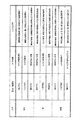
図2は、動いているときのタイヤの自然な熱力学的加熱によるタイヤ圧力およびタイヤ温度の変化から、タイヤの動きをどのように推測し得るかを示す表を示している。換言すれば、動きそれ自体は検知しておらず、むしろ圧力および温度変化を用いて、プロセス・コントローラ22はタイヤの動きが起こりつつあるのか、或いは止まっているのかを判断する。例示した形態においては、タイヤ空気圧およびタイヤ空気温度のみを知る必要がある。最新の空気圧の読み取り値が、以前の空気圧の読み取り値よりも小さいと仮定する。このように減少している場合、圧力/温度(P/T)比は減少しているか、或いは一定のいずれかである。圧力/温度比が増加する可能性はない。何故なら、増加する場合は、理想気体の法則にもとづく有効な状態ではないからである。圧力/温度比が、空気圧の減少に対応して減少している場合には、タイヤ内部の気体の「質量」は減少しており、タイヤの状態は空気漏れである。プロセス・コントローラ22は、短い測定およびRF送信間隔を実施する。圧力/温度比が一定であるのに、圧力読み取り値が減少している場合には、タイヤの空気温度が比例して減少しているため、タイヤの状態は冷却状態である。車両は駐車中であると想定され、プロセス・コントローラ22は、より長い測定およびRF送信間隔を実施する。圧力/温度比が増加しているという無効な場合には、プロセス・コントローラ22は初期設定条件を実施して、強制的に短い測定およびRF送信間隔を行なって、新しい情報を収集し、空気圧を減少させ、かつ圧力/温度比を増加させている原因を判断する。
FIG. 2 shows a table showing how tire movement can be inferred from changes in tire pressure and tire temperature due to natural thermodynamic heating of the tire as it moves. In other words, the movement itself is not detected, but rather using pressure and temperature changes, the
最新のタイヤ空気圧の読み取り値が、以前のタイヤ空気圧の読み取り値に対して、一定であると仮定する。空気圧の読み取り値が一定である場合、圧力/温度比は、理想気体の法則により増加することも減少することもできないため、圧力/温度比は一定である。圧力/温度比が一定である場合には、タイヤは定常状態であると想定され、現在の測定および送信間隔が維持される。有効でない状態の場合にも、現在の測定および送信間隔は維持される。 Assume that the latest tire pressure reading is constant relative to the previous tire pressure reading. When the air pressure reading is constant, the pressure / temperature ratio is constant because the pressure / temperature ratio cannot be increased or decreased by the ideal gas law. If the pressure / temperature ratio is constant, the tire is assumed to be in a steady state and the current measurement and transmission interval is maintained. The current measurement and transmission interval is maintained even in the invalid state.
最新のタイヤ空気圧の読み取り値が、以前のタイヤ空気圧の読み取り値に対して、増加していると仮定する。増加している場合、圧力/温度比は、増加しているかまたは一定である。圧力/温度比が減少する可能性はない。何故なら、減少する場合は、理想気体の法則にもとづく有効な状態ではないからである。圧力/温度比が増加している場合には、気体の質量は増加しており、タイヤに空気が加えられている。プロセス・コントローラ22は、短い測定およびRF送信間隔を実施する。圧力/温度比が一定であるのに、圧力読み取り値が増加している場合には、タイヤの空気温度が比例して増加しているため、タイヤの状態は加熱状態である。気体の質量は一定であるため、車両は動いていると想定され、プロセス・コントローラ22は、より短い測定およびRF送信間隔を実施する。圧力/温度比が減少しているという無効な場合には、プロセス・コントローラ22は初期設定条件を実施して、強制的に短い測定およびRF送信間隔を行なって、新しい情報を収集し、空気圧を増加させ、かつ圧力/温度比を減少させている原因を判断する。前述した無効な状態は、タイヤ温度の急激な変動に対する圧力センサ16および温度センサ18の時間応答の差に起因して、ホイール・モジュール11の実際の構造において存在するように見える可能性がある。
Assume that the latest tire pressure reading has increased relative to the previous tire pressure reading. If increasing, the pressure / temperature ratio is increasing or constant. There is no possibility of the pressure / temperature ratio decreasing. This is because the decrease is not an effective state based on the ideal gas law. When the pressure / temperature ratio is increasing, the mass of the gas is increasing and air is being added to the tire. The
全体として、この動作によって、ホイール・モジュール11による測定と送信との間の推移が遅くなるかまたは高頻度になる所定の状態がもたらされる。これらの状態は、以下の基準に要約することができる。
(1)圧力が増加した場合には、測定および送信をより短い間隔で開始する。
(2)圧力が減少し、かつ圧力/温度比が一定でない場合には、測定および送信をより短い間隔で開始する。
(3)圧力が減少し、かつ圧力/温度比が一定の場合には、測定および送信をより長い間隔で開始する。
(4)圧力が一定の場合には、上記3つの場合のうちの1つの場合が発生するまで、現在の測定および送信間隔を維持する。
(5)圧力読み取り値の短期平均値を圧力読み取り値のはるかに長い長期平均値と比較することによって、予想よりも早い圧力降下が判断される可能性がある場合には、測定および送信をより短い間隔で開始する。
Overall, this action results in certain conditions where the transition between measurement and transmission by the
(1) If the pressure increases, start measuring and transmitting at shorter intervals.
(2) If the pressure decreases and the pressure / temperature ratio is not constant, start the measurement and transmission at shorter intervals.
(3) If the pressure decreases and the pressure / temperature ratio is constant, start measuring and transmitting at longer intervals.
(4) If the pressure is constant, maintain the current measurement and transmission interval until one of the three cases occurs.
(5) If a short-term average of pressure readings is compared to a much longer long-term average of pressure readings, if there is a possibility that a faster pressure drop than expected can be determined, measure and send more Start with a short interval.
その他の基準因子は、圧力変化が発生する時間間隔を規定することである。経験的なデータが示唆するところによれば、動きによって生じるタイヤの加熱は、車両速度プロファイルに拘わらず、ほぼ5分以内における10〜20kPaの圧力増加によって特徴付けられる。車両の駐車によるタイヤの冷却では、ほぼ45分以内に圧力が10〜20kPaだけ減少する。 Another criterion is to define the time interval at which pressure changes occur. Empirical data suggests that tire heating caused by movement is characterized by a pressure increase of 10-20 kPa within approximately 5 minutes, regardless of the vehicle speed profile. In cooling the tire by parking the vehicle, the pressure decreases by 10-20 kPa within approximately 45 minutes.
動いている段階では、圧力測定はかなり頻繁に行なわれ、受信器部分12は、いかなる圧力の突然の変化であっても、これを認識することができる。しかし、車両が駐車状態の間は、圧力の突然の変化がしばらくの間報告されないこともある。このことは、車両が実際に駐車中のときには、心配すべき事ではないかもしれない。しかし、車両が実際には動いているのに、駐車状態が誤って示されている場合には、問題となる可能性がある。このような状況が運転中に発生する可能性としては、車両が、水で濡れた道路に入ることまたは雪もしくは雨に遭遇することによって、タイヤが冷却されている場合ある。車両が所定の時間の間駐車され、かつ空気がタイヤに加えられた場合には、システム10による送信を速くして、以前におけるいかなる低膨張警告もリセットするようにすることも望ましい。すなわち、極めて短い時間の間に発生する空気付加または漏れによる突然の変化を捕らえるためには、駐車または移動モード中の最長の測定間隔を30秒未満とする必要がある。
In the moving phase, pressure measurements are made fairly frequently and the
図3に示すのは、内部の電気機械スイッチを使うことも、外部デバイスから信号を送信することもない、空気式タイヤの熱力学的な動き検出方法を示すフローチャートである。本明細書に記載の動き検出方法によって、システム10は、空気が十分に入っていないタイヤを適時に検出することができる。何故なら、長期平均の読み取り値から、20kPa超の空気圧変化として動き検出を行なうことができるからである。検出は、従来の移動平均(RA)フィルタを用いて、最新の読み取り値を以前のすべての読み取り値のパーセンテージに加えることによって行なうことができる。
Pk+l=[(N−1)(Pk−l)+Pk]/N
ここで、
Pk−1は、以前の平均値であり、
Pkは、現在の圧力読み取り値であり、
Pk+lは、新しい平均値であり、
Nは、移動平均の重みである。
FIG. 3 is a flowchart showing a method for detecting the thermodynamic motion of a pneumatic tire without using an internal electromechanical switch or transmitting a signal from an external device. The motion detection method described herein allows the
P k + l = [(N−1) (P k−1 ) + P k ] / N
here,
P k−1 is the previous average value,
P k is the current pressure reading,
P k + l is the new average value,
N is the weight of the moving average.
一般的に、移動平均フィルタは、サンプル間の間隔をN倍した値に等しい時定数を有する。たとえば、Nの値が8に等しく、サンプル時間が30秒である場合、時定数は240秒となる。2つの移動平均フィルタを用いることで、圧力の短期変動については、8に等しいNの値を用いてフィルタリングすることができ、長期変動については、128に等しいNの値を用いてフィルタリングすることができる。動きを推測する他の方法を用いても良いことを理解されたい。長時間の測定および短時間の測定を用いて動きを予測するものであれば、どんな時変型方法を用いても良い。このような時変型方法では、たとえば、異なる平均化技術を用いても良いし、時間読み取り値の間の差を計算しても良い。 In general, a moving average filter has a time constant equal to N times the interval between samples. For example, if the value of N is equal to 8 and the sample time is 30 seconds, the time constant is 240 seconds. By using two moving average filters, a short-term variation in pressure can be filtered using a value of N equal to 8, and a long-term variation can be filtered using a value of N equal to 128. it can. It should be understood that other methods of inferring movement may be used. Any time-varying method may be used as long as the motion is predicted using a long-time measurement and a short-time measurement. In such a time variant method, for example, different averaging techniques may be used, or the difference between time readings may be calculated.
タイヤ/空気システムの挙動は、RC回路に極めて類似しており、漏れに応答する圧力の減衰により、ほぼ指数関数的に圧力は低下する。キャパシタからの電流流出がキャパシタの電圧減少に関連していることと極めて類似しており、タイヤの空気流量がタイヤ内部の圧力ヘッドの減少に関連する。したがって、与えられたいかなる漏れであっても、特徴的な時定数を有する単純な指数関数的な応答をするとみなすことができる。
P=(P0)e(−t)/TC
ここで、
Pは、圧力の現在値であり、
P0は、初期開始圧力であり、
tは、経過時間であり、
TCは、時定数である。
The behavior of the tire / air system is very similar to the RC circuit, with the pressure decreasing approximately exponentially due to the decay of pressure in response to leakage. The current outflow from the capacitor is very similar to that associated with a decrease in capacitor voltage, and the tire airflow is associated with a decrease in the pressure head inside the tire. Thus, any given leak can be considered as a simple exponential response with a characteristic time constant.
P = (P 0 ) e (−t) / TC
here,
P is the current value of pressure,
P 0 is the initial starting pressure,
t is the elapsed time,
TC is a time constant.
時定数(TC)とは、指数が1に等しくなって、圧力値がその初期値から63.2%だけ降下したときの時間の値である。 The time constant (TC) is a value of time when the index is equal to 1 and the pressure value drops by 63.2% from its initial value.
図3に示すように、開始30の後に、ステップ32においてタイヤ空気圧を読み取る。ステップ34において、タイヤの空気温度を読み取る。この情報を用いて、ステップ36において、圧力対温度(P/T)比を計算する。以前のP/T読み取り値を用いて、ステップ38において、P/T比の長期変化曲線を計算する。これについては後述する。ステップ40において、フィルタリング後の変化曲線を計算する。これについては後述する。ステップ42において、長期変化曲線を計算する。これについては後述する。次の判定ステップ46において、フィルタリング後の変化曲線の値が長期変化曲線の値よりも大きいか否かについて、判断を下す。その判断が「否定」の場合、判定ステップ48において、フィルタリング後の変化曲線が長期変化曲線よりも小さいか否かについて、判断を下す。判断が「否定」の場合、プロセスはステップ32から再び始まり、長いかまたは短いかのいずれかの測定レート時間が満了した後にプロセス・コントローラ22の制御の下で、圧力および温度を読み取ることによって、本方法を繰り返す。ステップ48における判断が「肯定」の場合、判定ステップ50において、圧力対温度比がP/T長期変化曲線よりも小さいか否かについて判断を下す。判断が「否定」の場合、ステップ52において、タイヤが冷却中でありしたがって車両が停止したと判断される。ステップ52に続いて、ステップ54において、測定および送信レートを減少させる。ステップ50における判定が「肯定」の場合、ステップ56において、空気漏れがあると判断される。ステップ56に続いて、ステップ58において、測定および送信レートを増加させる。ステップ54および58のそれぞれに応答して、任意選択のステップ66を行なう。ステップ66において、長期変化曲線の値を変更して、フィルタリング後の変化曲線の現在値と等しくなるようにする。仮にこの変更が行なわれたならば、判定ステップ46および48に対する分解能は鋭くなる。ステップ66の後に、ステップ32の最初に戻り、長いかまたは短いかのいずれかの測定レート時間が満了した後にプロセス・コントローラ22の制御の下で、圧力および温度を読み取ることによって、本方法を繰り返す。ステップ46の判断が「肯定」の場合、判定ステップ60において、P/T比がP/T長期変化曲線よりも大きいか否かについて判断を下す。ステップ60における判定が「肯定」の場合、ステップ64において、空気がタイヤに加えられたと判断され、その判断の後に、ステップ58において、測定および送信レートを増加させる。ステップ60における判定が「否定」の場合、ステップ62において、タイヤは加熱されており、車両は動いていたと判断される。ステップ62の後に、ステップ58において、測定および送信レートを増加させる。
As shown in FIG. 3, after the
ステップ40のフィルタリング後の変化曲線およびステップ42の長期変化曲線をより良く理解するために、図4を参照する。図4のグラフは、時間に対する圧力70の初期読み取り値の変化のプロット(100パーセントから0パーセント)である。単に説明を目的として、検知されるタイヤ圧力は、図示したように時間に対して減衰していくものと仮定する。移動平均フィルタによって、長期変化曲線72を計算する。これは、式3のNの値が小さい移動平均フィルタを用いることで時間に対する圧力の短期変動をフィルタリングすることによって、およびNの値が大きい移動平均フィルタを用いることで時間に対する長期の値を保持することによって、行なわれる。フィルタリング後の変化曲線74は、ノイズがフィルタリングされた圧力の短期変動または変化を表わす。長期変化曲線72は、圧力変化分析に使用するベースラインの圧力を表わす。この方法では、種々のタイヤ様式および推奨される膨張レベルに対して、特定の圧力レベルをホイール・モジュール11内でプログラムすることも、或いは維持することも必要としない。図4の説明図では、その2本の曲線間の差が、時間に対して増加している。このことは、長期変化曲線からフィルタリング後の変化曲線を引いた曲線76によって示されている。図4の例では、判定ステップ46および判定ステップ48において用いられる閾値80を設定することができる。その閾値のパーセンテージまたは量は、比較的小さければどんな値であっても良い。たとえば10パーセント、15パーセント、20パーセント等である。同様に、P/T比の現在値は、圧力フィルタリング後の曲線データを用いているため、効果が平均化されている。またP/T比の現在値は、Nに対する値が大きい他の移動平均フィルタを用いて長期変化曲線を有することができる。判定ステップ50において、検知された圧力および温度ならびに結果として生じる比および長期変化曲線72を用いて、空気漏れがあるか否かを、または車両が単に冷却中であるのか否かを判断し、その判定によって、電力管理回路14が測定レートを増加させるのか、或いは減少させるのか(すなわち、ホイール・モジュール11が低電力のバッテリ・モードに入るのか、或いは通常電力のバッテリ・モードに入るのか)が判断される。
To better understand the filtered change curve of
動きを検出する感度は調整することができる。これは、フィルタリング後の変化曲線74および長期変化曲線72で用いられる変数Nの値を変化させることによって、および判定を下すために用いられる2本の曲線間差の閾値80を変化させることによって行なわれる。
The sensitivity for detecting motion can be adjusted. This is done by changing the value of the variable N used in the filtered change curve 74 and the long-
以上のように、動き検知スイッチを用いなくても、動きを検知し得る。さらに、移動平均フィルタを用いる場合、既存の読み取り値を用いており、電力を消費し得る追加データ測定値の付加は行なわない。バッテリ電力の節約を、車両が移動中の場合と車両が駐車中の場合との間の測定および送信間隔を変更することによって行なっているが、動き検知デバイスに電力を供給する必要性により、バッテリ電力が消費されることはない。 As described above, a motion can be detected without using a motion detection switch. Furthermore, when using a moving average filter, existing readings are used and no additional data measurements that can consume power are added. Battery power is saved by changing the measurement and transmission interval between when the vehicle is moving and when the vehicle is parked, but the need to supply power to the motion sensing device No power is consumed.
本明細書で教示される推測による動き検知方法のさらなる利点は、低膨張タイヤがスペアであるのか、または対象車両の所定位置にあるロード・タイヤであるのかを識別することに関連している。ロード・タイヤを、空気が不十分となったためにスペア・タイヤと交換したときには、空気が不十分なタイヤが原因で、情報処理回路28によって警告デバイスが駆動し続ける可能性がある。これは、空気が不十分なタイヤを車両内に詰め込むときでさえ、タイヤ検知に付随する基準の一部として動き検知を用いなかった場合には、起こり得る。多くのシステムでは、ドライバ用に用いる警告ランプは1つであるため、スペアが供給されるまでアラーム状態は存続する。しかし、動き検知能力がタイヤ検知システム10に存在するために、ホイール・モジュール11は、任意の他のデータに加えて、ホイール・モジュール11が動いているのか、或いは動いていないのかをホイール・モジュール11がフラグ・ビットを用いて判断したことを、送信することができる。情報処理回路28がこのフラグ・ビット状態を用いて、空気漏れが存在するタイヤからはまったく動きが生じていなかったことを判断して、アラーム状態を無効にすることができる。本明細書で説明した方法を用いることで、動きがないことを検出できるため、車両のロード・サービスにおいて不良スペアを不良タイヤと識別することができる。
A further advantage of the speculative motion detection method taught herein relates to identifying whether the low expansion tire is a spare or a road tire in place on the subject vehicle. When the road tire is replaced with a spare tire due to insufficient air, the warning device may continue to be driven by the
以上により、動作間隔を変化させることによってバッテリ消費量を減らすことを目的とした、推測による動き検知による電力管理を有するタイヤ検知システムが提供されたことは、明らかである。この推測による動き方法は、動きに伴う圧力上昇に基づいており、必要に応じて、測定間隔を延ばすこと、および移動平均による漏れ検出方法を用いて信号を送る測定間隔を早くすることを行なっている。 From the above, it is clear that a tire detection system having power management by motion detection based on estimation intended to reduce battery consumption by changing the operation interval has been provided. The motion method based on this estimation is based on the pressure increase caused by the motion. If necessary, the measurement interval is extended and the measurement interval for sending a signal using the moving average leak detection method is increased. Yes.
説明のために選択された本明細書の実施形態に対する種々の変形および変更は、当業者には容易に想起される。たとえば、一意的なタイヤ識別子をRF送信器によって送信して、各タイヤ位置についての表示結果があるようにしても良い。タイヤ圧力センサの所望する寿命および特徴に応じて、種々の型式のバッテリを用いても良い。プロセス・コントローラ22を、ステート・マシーン、マイクロコントローラ、ロジック回路、またはこれらの組み合わせによって、実現しても良い。プロセス・コントローラ22が、RFまたはプログラム制御下にあって、タイヤ圧力の監視が、所定の信号またはコマンド命令を受け取るまで開始しないようになっていても良い。タイヤ内側のホイール・モジュール11の種々の物理的な具体化および配置を、実施しても良い。ホイール・モジュール11を、空気式タイヤの内側に実装して任意の形式の車両で使用するようにしても良い。また用語「空気」は、任意の種類の気体または気体組成物であると定義する。このような変更および変形は、これらが本発明の技術思想から逸脱しない程度に、本発明の範囲に含まれることが意図されている。本発明の範囲は、添付の特許請求の範囲を適正に解釈することによってのみ評価される。
Various modifications and alterations to the embodiments herein selected for illustration will readily occur to those skilled in the art. For example, a unique tire identifier may be transmitted by an RF transmitter so that there is a display result for each tire position. Various types of batteries may be used depending on the desired lifetime and characteristics of the tire pressure sensor. The
以上、利益、他の利点、および問題に対する解決方法を、特定の実施形態について説明してきた。しかし、この利益、利点、問題に対する解決方法、および何らかの利益、利点、または解決方法を生じさせるか、或いはより明瞭になり得るいかなる構成要素も、いずれかまたはすべての特許請求の範囲の重大で、必須で、または本質的な特徴または構成要素であると、解釈すべきではない。本明細書で用いる場合、単語「備える(comprises)」、「備えている(comprising)」、またはそれらの何らかの他の変形は、非排他的に含めることに及ぶことが意図されている。そのため、構成要素の一覧を備えるプロセス、方法、物品、または装置は、これらの構成要素が含まれるだけでなく、明白には記載されていないか、またはこのようなプロセス、方法、物品、または装置に固有の他の構成要素も含み得る。単語「ある(a or an)」は、本明細書で用いる場合、1つ以上であると定義される。単語「複数の(plurality)」は、本明細書で用いる場合、2つ以上であると定義される。単語「別の(another)」は、本明細書で用いる場合、少なくとも2番目またはそれ以上であると定義される。単語「含んでいる(including)」および/または「有している(having)」は、本明細書で用いる場合、「備えている(comprising)」として定義される(すなわち、オープン・ランゲージ)。単語「接続された(coupled)」は、本明細書で用いる場合、「結合された(connected)」と定義されるが、必ずしも直接的にではなく、また必ずしも機械的にでもない。 Thus, benefits, other advantages, and solutions to problems have been described in particular embodiments. However, any benefit, advantage, solution to a problem, and any component that may produce or become clearer in any benefit, advantage, or solution is critical to any or all claims, It should not be construed as an essential or essential feature or component. As used herein, the words “comprises”, “comprising”, or some other variation thereof are intended to cover non-exclusive inclusions. As such, a process, method, article, or device comprising a list of components not only includes these components, but is not explicitly described, or such a process, method, article, or device Other components unique to the can also be included. The word “a or an” as used herein is defined as one or more. The word “plurality” as used herein is defined as two or more. The word “another”, as used herein, is defined as at least a second or more. The words “including” and / or “having” as used herein are defined as “comprising” (ie, open language). The word “coupled” as used herein is defined as “connected”, but not necessarily directly, nor necessarily mechanically.
Claims (12)
圧力センサによって空気圧を検知すること、
温度センサによって空気温度を検知すること、
前記空気圧が時間に対して増加しているのか、或いは減少しているのかを判断すること、
タイヤの加速または運動を直接に検知することなく、前記空気圧と前記空気温度との比が時間に対して増加しているのか、減少しているのか、或いは一定であるのかを判断することによって、タイヤが動いていることを推測すること、
前記空気圧の検知および前記空気温度の検知を、タイヤが動いているときよりも長時間の測定間隔で行なうことにより、タイヤが動いていないときのタイヤ圧力監視システムの電力を節約すること、
を備えるタイヤ圧力監視システムにおける電力管理方法。A power management method in a tire pressure monitoring system showing when the air pressure inside a tire falls below a predetermined amount,
Detecting air pressure with a pressure sensor,
Detecting the air temperature with a temperature sensor,
Determining whether the air pressure is increasing or decreasing over time;
By determining whether the ratio of the air pressure and the air temperature is increasing, decreasing or constant over time without directly detecting tire acceleration or motion, Guessing that the tires are moving,
Sensing and detection of the air temperature of the air, by performing a long time measurement interval than when that is moving tire, to conserve power the tire pressure monitoring system when not moving tire,
A power management method in a tire pressure monitoring system comprising:
前記空気圧が時間に対して減少し、かつ前記空気圧と前記空気温度との比が実質的に一定であるときには、タイヤは動いていないという推測によって判定すること、
前記空気圧の検知および前記空気温度の検知を、タイヤが動いているときよりも長時間の測定間隔で行なって電力を節約すること、
を備える方法。The method of claim 1 further comprises:
When the air pressure decreases over time and the ratio of the air pressure and the air temperature is substantially constant, the determination is made by speculation that the tire is not moving;
Saving power by detecting the air pressure and the air temperature at longer measurement intervals than when the tire is moving;
A method comprising:
タイヤ圧力の変化の長期平均と、1つまたは複数の移動平均フィルタを用いることによるタイヤ圧力の変化のフィルタリング後の平均との比較に基づいて、測定間隔の時間を変更することを備える、方法。The method of claim 1 further comprises:
Changing the time of the measurement interval based on a comparison of the long-term average of the change in tire pressure and the filtered average of the change in tire pressure by using one or more moving average filters.
タイヤ圧力監視システムに電力を供給するためのバッテリと、
タイヤ内部の空気圧を検知するための圧力センサと、
タイヤ内部の空気温度を検知するための温度センサと、
タイヤの加速または運動を直接に検知することなく、前記空気圧が時間に対して増加しているのか、或いは減少しているのかを判断し、かつ前記空気圧と前記空気温度との比が時間に対して増加しているのか、減少しているのか、或いは一定であるのかを判断することによって、タイヤが動いていることを推測する制御回路と、
前記バッテリ、前記圧力センサ、および前記温度センサに接続され、かつ前記圧力センサおよび前記温度センサに、特定の測定間隔で選択的に電力を供給するための電力管理回路であって、該測定間隔は前記制御回路がタイヤは動いていると推測したときの方がタイヤは動いていないと推測したときに比べて短い、電力管理回路と、
を備えるタイヤ空気圧監視システム。A tire pressure monitoring system inside a tire,
A battery for supplying power to the tire pressure monitoring system;
A pressure sensor for detecting the air pressure inside the tire;
A temperature sensor for detecting the air temperature inside the tire;
Without directly detecting tire acceleration or movement, it is determined whether the air pressure is increasing or decreasing with time, and the ratio of the air pressure to the air temperature is with respect to time. A control circuit that estimates that the tire is moving by determining whether it is increasing, decreasing, or constant,
A power management circuit connected to the battery, the pressure sensor, and the temperature sensor, and for selectively supplying power to the pressure sensor and the temperature sensor at a specific measurement interval, the measurement interval being A power management circuit that is shorter when the control circuit estimates that the tire is moving than when it is estimated that the tire is not moving, and
Tire pressure monitoring system comprising.
前記制御回路に接続された送信器であって、低いタイヤ圧力の検出に応答して前記制御回路によって生成されるアラーム信号を送信するための送信器と、
タイヤの外側に配置され、かつ前記アラーム信号を受信するための受信器と、
前記受信器に接続され、かつタイヤの外側に配置された処理回路であって、前記アラーム信号をバッファリングする処理回路と、
前記処理回路に接続されたディスプレイであって、前記アラーム信号の駆動を視覚的または聴覚的に表示するディスプレイと、
を備えるタイヤ圧力監視システム。The tire pressure monitoring system according to claim 6, further comprising:
A transmitter connected to the control circuit for transmitting an alarm signal generated by the control circuit in response to detection of a low tire pressure;
A receiver disposed outside the tire and for receiving the alarm signal;
A processing circuit connected to the receiver and disposed outside the tire, the processing circuit buffering the alarm signal;
A display connected to the processing circuit for visually or audibly displaying the driving of the alarm signal;
A tire pressure monitoring system comprising:
Applications Claiming Priority (2)
| Application Number | Priority Date | Filing Date | Title |
|---|---|---|---|
| US41948702P | 2002-10-18 | 2002-10-18 | |
| PCT/US2003/007219 WO2004037566A1 (en) | 2002-10-18 | 2003-02-12 | Apparatus and method for power management in a tire pressure monitoring system |
Publications (3)
| Publication Number | Publication Date |
|---|---|
| JP2006502913A JP2006502913A (en) | 2006-01-26 |
| JP2006502913A5 JP2006502913A5 (en) | 2008-02-07 |
| JP4162656B2 true JP4162656B2 (en) | 2008-10-08 |
Family
ID=32176470
Family Applications (1)
| Application Number | Title | Priority Date | Filing Date |
|---|---|---|---|
| JP2004546652A Expired - Fee Related JP4162656B2 (en) | 2002-10-18 | 2003-02-12 | Apparatus and method for power management in tire pressure monitoring system |
Country Status (7)
| Country | Link |
|---|---|
| US (1) | US7242285B2 (en) |
| EP (1) | EP1556234B1 (en) |
| JP (1) | JP4162656B2 (en) |
| KR (1) | KR100941014B1 (en) |
| CN (1) | CN100335302C (en) |
| AU (1) | AU2003220997A1 (en) |
| WO (1) | WO2004037566A1 (en) |
Families Citing this family (50)
| Publication number | Priority date | Publication date | Assignee | Title |
|---|---|---|---|---|
| US7429801B2 (en) * | 2002-05-10 | 2008-09-30 | Michelin Richerche Et Technique S.A. | System and method for generating electric power from a rotating tire's mechanical energy |
| DE102004004292A1 (en) * | 2004-01-28 | 2005-09-08 | Siemens Ag | Arrangement and method for bidirectionally transmitting signals in a motor vehicle |
| US9566836B2 (en) | 2004-03-04 | 2017-02-14 | Infineon Technologies Ag | Apparatus and method for determining a state parameter of an object to be monitored |
| DE102004010665B4 (en) * | 2004-03-04 | 2014-09-18 | Infineon Technologies Ag | Device and method for determining a state parameter of an object to be monitored |
| US10532617B2 (en) * | 2004-03-04 | 2020-01-14 | Infineon Technologies Ag | Apparatus and method for determining a state parameter of an object to be monitored |
| FR2871736B1 (en) * | 2004-06-18 | 2006-09-01 | Johnson Contr Automotive Elect | METHOD FOR DETECTING RAPID LEAKAGE OF A MOTOR VEHICLE TIRE |
| JP4289561B2 (en) * | 2004-12-24 | 2009-07-01 | 横浜ゴム株式会社 | Vehicle abnormality detection method and apparatus, and sensor unit thereof |
| US7668695B2 (en) * | 2005-02-22 | 2010-02-23 | Bridgestone Corporation | Sensor malfunction determination device and sensor malfunction determination method |
| JP2006287523A (en) * | 2005-03-31 | 2006-10-19 | Taiyo Nippon Sanso Corp | Liquid level monitor terminal, monitor data transmission system, and monitor data transmission method |
| JP2006306344A (en) * | 2005-05-02 | 2006-11-09 | Nissan Motor Co Ltd | Tire air pressure monitor |
| EP1849627B1 (en) * | 2006-04-26 | 2012-03-14 | austriamicrosystems AG | Method for determining a tire position in a tire pressure measurement system |
| JP4752661B2 (en) * | 2006-08-01 | 2011-08-17 | 株式会社デンソー | Transmitter and tire pressure detecting device having the same |
| US7498931B2 (en) * | 2006-08-28 | 2009-03-03 | Lear Corporation | Tire pressure monitoring system |
| JP5019839B2 (en) * | 2006-10-04 | 2012-09-05 | 株式会社ブリヂストン | Tire information management system |
| DE102008031498B4 (en) * | 2008-07-03 | 2012-03-08 | Infineon Technologies Ag | Clock determination of a sensor |
| DE102008014537B4 (en) | 2008-03-15 | 2020-04-23 | Continental Teves Ag & Co. Ohg | Tire condition monitor |
| US7900521B2 (en) * | 2009-02-10 | 2011-03-08 | Freescale Semiconductor, Inc. | Exposed pad backside pressure sensor package |
| JP2011099833A (en) * | 2009-11-09 | 2011-05-19 | Denso Corp | Mechanical quantity detection device |
| FR2953766B1 (en) * | 2009-12-15 | 2012-02-17 | Continental Automotive France | METHOD FOR ADJUSTING A TIME BASE OF A PNEUMATIC PRESSURE MEASURING UNIT |
| FR2958065B1 (en) * | 2010-03-24 | 2012-04-20 | Continental Automotive France | METHOD AND OPTIMIZED TRANSMISSION UNIT FOR MEASURING PARAMETERS OF VEHICLE TIRES |
| JP5731299B2 (en) * | 2011-07-04 | 2015-06-10 | 株式会社東海理化電機製作所 | Control device for tire pressure monitoring system |
| US8818619B2 (en) * | 2012-08-02 | 2014-08-26 | Trw Automotive U.S. Llc | Method and apparatus for determining tire condition using ideal gas law |
| KR101349854B1 (en) * | 2012-10-25 | 2014-02-13 | 현대오트론 주식회사 | Tire pressure monitoring module, tire pressure monitoring system comprising the same, and method for performing auto-location of the same |
| KR101349857B1 (en) | 2012-10-30 | 2014-01-09 | 현대오트론 주식회사 | Tire pressure monitoring module, tire pressure monitoring system comprising the same, and method for performing auto-location of the same |
| KR101349855B1 (en) | 2012-10-30 | 2014-01-09 | 현대오트론 주식회사 | Tire pressure monitoring module, tire pressure monitoring system comprising the same, and method for performing auto-location of the same |
| KR101349856B1 (en) | 2012-10-30 | 2014-01-09 | 현대오트론 주식회사 | Tire pressure monitoring module, tire pressure monitoring system comprising the same, and method for performing auto-location of the same |
| KR101388622B1 (en) | 2012-12-21 | 2014-04-24 | 현대오트론 주식회사 | Tire pressure monitoring module, tire pressure monitoring system comprising the same, and method for performing auto-location of the same |
| US9409450B2 (en) * | 2013-10-11 | 2016-08-09 | Arvinmeritor Technology, Llc | Tire inflation system and method of control |
| FR3011200B1 (en) * | 2013-09-27 | 2015-09-04 | Renault Sa | METHOD AND SYSTEM FOR MONITORING A TIRE |
| JP6545265B2 (en) | 2014-12-16 | 2019-07-17 | ティーアールダブリュー・オートモーティブ・ユーエス・エルエルシー | Method and apparatus for tire filling assistance |
| US10449811B2 (en) | 2015-06-15 | 2019-10-22 | Infineon Technologies Ag | Tire monitoring system and method |
| CN106427418B (en) * | 2015-08-07 | 2018-06-19 | 联创汽车电子有限公司 | TPMS systems and its control method |
| EP3165384B1 (en) * | 2015-09-17 | 2019-07-17 | Pacific Industrial Co., Ltd. | Tire state detection device |
| FR3041286B1 (en) * | 2015-09-22 | 2017-10-06 | Continental Automotive France | METHOD AND UNIT OF MEASUREMENT FOR MOTOR VEHICLE |
| FR3045498B1 (en) | 2015-12-18 | 2017-12-22 | Continental Automotive France | METHOD FOR ADAPTING THE STRATEGY FOR ACQUIRING RADIATION ACCELERATION MEASUREMENTS OF WHEELS OF A VEHICLE |
| GB2545901B (en) * | 2015-12-22 | 2020-06-03 | Schrader Electronics Ltd | Apparatus and method for detecting vehicle motion in a tyre pressure monitoring system |
| US9739239B2 (en) | 2016-01-22 | 2017-08-22 | Ford Global Technologies, Llc | System and methods for controlling fuel vapor canister purge operations |
| CN109982872A (en) * | 2016-10-05 | 2019-07-05 | 索莱拉控股股份有限公司 | Vehicle tyre monitors system and method |
| CN106515320A (en) * | 2016-10-31 | 2017-03-22 | 江苏博锐格电子科技有限公司 | Tire monitoring sensor module and air leakage early-warning method |
| US11161628B2 (en) * | 2016-11-01 | 2021-11-02 | Textron Innovations, Inc. | Remote aircraft preflight verification |
| JP6843006B2 (en) | 2017-06-26 | 2021-03-17 | 株式会社ブリヂストン | Tire pressure monitoring system, tire pressure monitoring method, tire pressure monitoring program and vehicle |
| US11420485B2 (en) | 2017-11-10 | 2022-08-23 | Compagnie Generale Des Etablissements Michelin | Method for detecting a leak in a tire of a stationary vehicle |
| JP6936766B2 (en) * | 2018-05-14 | 2021-09-22 | Kyb株式会社 | Fluid leak detection system |
| DE102020205658A1 (en) * | 2020-05-05 | 2021-11-11 | Continental Reifen Deutschland Gmbh | Tire anomalies |
| GB2617599A (en) * | 2022-04-13 | 2023-10-18 | Airbus Operations Ltd | An aircraft tire monitoring device |
| GB2618612A (en) * | 2022-05-13 | 2023-11-15 | Airbus Operations Ltd | A method of determining a tire performance characteristic of a tire |
| GB2618611A (en) * | 2022-05-13 | 2023-11-15 | Airbus Operations Ltd | A tire performance monitoring system |
| GB2618613A (en) * | 2022-05-13 | 2023-11-15 | Airbus Operations Ltd | A method of determining a tire performance characteristic of a tire |
| GB2618614A (en) * | 2022-05-13 | 2023-11-15 | Airbus Operations Ltd | A method of determining a tire performance characteristic of a tire |
| KR102539014B1 (en) * | 2022-07-07 | 2023-06-01 | 주식회사 대영파워펌프 | Apparatus to prevent freezing in the booster pump system and method for driving thereof |
Family Cites Families (15)
| Publication number | Priority date | Publication date | Assignee | Title |
|---|---|---|---|---|
| US5297424A (en) * | 1990-03-07 | 1994-03-29 | Monroe Auto Equipment Company | Telemetry system for tire pressure and temperature sensing |
| US5900809A (en) * | 1991-08-08 | 1999-05-04 | Michelin Recherche Et Technique, S.A. | Method for processing pressure and temperature measurements in a tire monitoring system |
| US5886624A (en) * | 1991-08-08 | 1999-03-23 | Compagnie General Des Etablissements Michelin-Michelin & Cie | Method for processing pressure and temperature measurements in a tire monitoring system |
| US5694111A (en) * | 1996-12-23 | 1997-12-02 | Huang; Tien-Tsai | Tire pressure indicator |
| GB9811154D0 (en) * | 1998-05-22 | 1998-07-22 | Automotive Technologies Limite | A remote tyre pressure monitoring system |
| TW361392U (en) * | 1998-06-16 | 1999-06-11 | Huang tian cai | Power switch gear of the tire pressure alarm |
| US6369712B2 (en) * | 1999-05-17 | 2002-04-09 | The Goodyear Tire & Rubber Company | Response adjustable temperature sensor for transponder |
| US6809637B1 (en) * | 1999-09-03 | 2004-10-26 | The Goodyear Tire & Rubber Company | Monitoring a condition of a pneumatic tire |
| EP1092570B1 (en) * | 1999-10-12 | 2005-09-14 | Pacific Industrial Co., Ltd. | Transmitter and transmitting method of tire air pressure monitoring apparatus |
| CN2403602Y (en) * | 1999-12-21 | 2000-11-01 | 周峰岳 | Sensor for tyre pressure monitoring apparatus |
| US6507276B1 (en) * | 2000-06-12 | 2003-01-14 | Cm Automotive Systems Inc. | Tire pressure monitoring system |
| US6278363B1 (en) * | 2000-07-14 | 2001-08-21 | Motorola, Inc | Method and system for monitoring air pressure of tires on a vehicle |
| US6535116B1 (en) * | 2000-08-17 | 2003-03-18 | Joe Huayue Zhou | Wireless vehicle monitoring system |
| EP1216854A3 (en) | 2000-12-19 | 2003-04-09 | Pacific Industrial Co., Ltd. | Transmitter and transmitting method of tire condition monitoring apparatus |
| DE10213266A1 (en) * | 2002-03-25 | 2003-10-23 | Infineon Technologies Ag | Tire pressure monitoring system |
-
2003
- 2003-02-12 US US10/533,271 patent/US7242285B2/en not_active Expired - Lifetime
- 2003-02-12 JP JP2004546652A patent/JP4162656B2/en not_active Expired - Fee Related
- 2003-02-12 CN CNB038242796A patent/CN100335302C/en not_active Expired - Fee Related
- 2003-02-12 KR KR1020057006687A patent/KR100941014B1/en active IP Right Grant
- 2003-02-12 EP EP03809486.8A patent/EP1556234B1/en not_active Expired - Lifetime
- 2003-02-12 WO PCT/US2003/007219 patent/WO2004037566A1/en active Application Filing
- 2003-02-12 AU AU2003220997A patent/AU2003220997A1/en not_active Abandoned
Also Published As
| Publication number | Publication date |
|---|---|
| EP1556234B1 (en) | 2016-08-17 |
| KR20050083780A (en) | 2005-08-26 |
| EP1556234A1 (en) | 2005-07-27 |
| US20060082451A1 (en) | 2006-04-20 |
| WO2004037566A1 (en) | 2004-05-06 |
| KR100941014B1 (en) | 2010-02-05 |
| US7242285B2 (en) | 2007-07-10 |
| CN1688454A (en) | 2005-10-26 |
| AU2003220997A1 (en) | 2004-05-13 |
| EP1556234A4 (en) | 2007-08-22 |
| JP2006502913A (en) | 2006-01-26 |
| CN100335302C (en) | 2007-09-05 |
Similar Documents
| Publication | Publication Date | Title |
|---|---|---|
| JP4162656B2 (en) | Apparatus and method for power management in tire pressure monitoring system | |
| EP1740922B1 (en) | Motion sensing for tire pressure monitoring | |
| JP5041005B2 (en) | Tire pressure monitoring device | |
| US7391308B2 (en) | Monitoring device, transceiver system and its control method | |
| CA2473492C (en) | Method for monitoring the pressure in pneumatic tires on vehicles | |
| US6450021B1 (en) | Transmitter and transmitting method of tire air pressure monitoring apparatus | |
| US20080190186A1 (en) | Smart Memory Alloy Control | |
| JP6128136B2 (en) | Tire pressure sensor unit, tire pressure notification device, and vehicle | |
| US20150149110A1 (en) | Tire pressure monitoring apparatus and method | |
| US9019094B2 (en) | Method for checking tire pressure in real time | |
| JP2004512216A (en) | Tire pressure monitoring system with low current consumption | |
| US6508100B2 (en) | System and method for resetting vehicle engine oil sensors | |
| EP1970223B1 (en) | Tire pressure sensor system with improved sensitivity and power saving | |
| EP1856330B1 (en) | System for detecting motion of an object | |
| US7034671B2 (en) | Alarm device for internal pressure of tire | |
| JP5006075B2 (en) | Tire pressure sensor system with improved sensitivity and power saving | |
| JP5346099B2 (en) | Tire pressure sensor system with improved sensitivity and power saving | |
| JP4087127B2 (en) | Tire pressure warning device | |
| Shaw | Motion Sensing Techniques and Analysis for Direct Tire Pressure Monitoring |
Legal Events
| Date | Code | Title | Description |
|---|---|---|---|
| A621 | Written request for application examination |
Free format text: JAPANESE INTERMEDIATE CODE: A621 Effective date: 20051118 |
|
| A521 | Request for written amendment filed |
Free format text: JAPANESE INTERMEDIATE CODE: A523 Effective date: 20071214 |
|
| A131 | Notification of reasons for refusal |
Free format text: JAPANESE INTERMEDIATE CODE: A131 Effective date: 20080408 |
|
| TRDD | Decision of grant or rejection written | ||
| A01 | Written decision to grant a patent or to grant a registration (utility model) |
Free format text: JAPANESE INTERMEDIATE CODE: A01 Effective date: 20080708 |
|
| A01 | Written decision to grant a patent or to grant a registration (utility model) |
Free format text: JAPANESE INTERMEDIATE CODE: A01 |
|
| A61 | First payment of annual fees (during grant procedure) |
Free format text: JAPANESE INTERMEDIATE CODE: A61 Effective date: 20080722 |
|
| FPAY | Renewal fee payment (event date is renewal date of database) |
Free format text: PAYMENT UNTIL: 20110801 Year of fee payment: 3 |
|
| R150 | Certificate of patent or registration of utility model |
Free format text: JAPANESE INTERMEDIATE CODE: R150 Ref document number: 4162656 Country of ref document: JP Free format text: JAPANESE INTERMEDIATE CODE: R150 |
|
| FPAY | Renewal fee payment (event date is renewal date of database) |
Free format text: PAYMENT UNTIL: 20110801 Year of fee payment: 3 |
|
| FPAY | Renewal fee payment (event date is renewal date of database) |
Free format text: PAYMENT UNTIL: 20120801 Year of fee payment: 4 |
|
| R250 | Receipt of annual fees |
Free format text: JAPANESE INTERMEDIATE CODE: R250 |
|
| FPAY | Renewal fee payment (event date is renewal date of database) |
Free format text: PAYMENT UNTIL: 20130801 Year of fee payment: 5 |
|
| R250 | Receipt of annual fees |
Free format text: JAPANESE INTERMEDIATE CODE: R250 |
|
| R250 | Receipt of annual fees |
Free format text: JAPANESE INTERMEDIATE CODE: R250 |
|
| R250 | Receipt of annual fees |
Free format text: JAPANESE INTERMEDIATE CODE: R250 |
|
| R250 | Receipt of annual fees |
Free format text: JAPANESE INTERMEDIATE CODE: R250 |
|
| R250 | Receipt of annual fees |
Free format text: JAPANESE INTERMEDIATE CODE: R250 |
|
| R250 | Receipt of annual fees |
Free format text: JAPANESE INTERMEDIATE CODE: R250 |
|
| S533 | Written request for registration of change of name |
Free format text: JAPANESE INTERMEDIATE CODE: R313533 |
|
| R350 | Written notification of registration of transfer |
Free format text: JAPANESE INTERMEDIATE CODE: R350 |
|
| R250 | Receipt of annual fees |
Free format text: JAPANESE INTERMEDIATE CODE: R250 |
|
| R250 | Receipt of annual fees |
Free format text: JAPANESE INTERMEDIATE CODE: R250 |
|
| R250 | Receipt of annual fees |
Free format text: JAPANESE INTERMEDIATE CODE: R250 |
|
| LAPS | Cancellation because of no payment of annual fees |