JP4160837B2 - Mattress equipment - Google Patents
Mattress equipment Download PDFInfo
- Publication number
- JP4160837B2 JP4160837B2 JP2003028758A JP2003028758A JP4160837B2 JP 4160837 B2 JP4160837 B2 JP 4160837B2 JP 2003028758 A JP2003028758 A JP 2003028758A JP 2003028758 A JP2003028758 A JP 2003028758A JP 4160837 B2 JP4160837 B2 JP 4160837B2
- Authority
- JP
- Japan
- Prior art keywords
- shaped member
- spring unit
- hook
- mattress device
- hinge mechanism
- Prior art date
- Legal status (The legal status is an assumption and is not a legal conclusion. Google has not performed a legal analysis and makes no representation as to the accuracy of the status listed.)
- Expired - Fee Related
Links
Images


Landscapes
- Mattresses And Other Support Structures For Chairs And Beds (AREA)
- Invalid Beds And Related Equipment (AREA)
Description
【0001】
【発明の属する技術分野】
この発明はベッドなどに用いられるマットレス装置に関する。
【0002】
【従来の技術】
たとえば、ベッドに用いられるマットレス装置は矩形板状に形成されたスプリングユニットや発泡弾性体などのクッション体を有し、このクッション体を外装地で被覆して構成されている。
【0003】
マットレス装置の上面に仰臥した利用者は、仰臥した姿勢で読書をしたり、テレビを見ることがある。その場合、頭部を水平状態よりも、わずかに持ち上げた状態の方が楽に読書をしたり、テレビを見ることができる。
【0004】
従来のマットレス装置では、利用者の頭部を上げた状態で保持するということができないから、利用者が頭部を上げるためには、枕の下に座布団を折り畳んで挟むということを行なっていた。しかしながら、そのようにして頭部を持ち上げるようにしたのでは安定性が悪いため、疲れ易いということがある。
【0005】
【発明が解決しようとする課題】
マットレス装置が用いられるベッドには、マットレス装置を載置した床板を複数に分割し、利用者の上半身に対応する部分を起伏駆動できるようにした、いわゆる起床式ベッドが知られている。起床式ベッドによれば、床板の一部を起上させることで、利用者の上半身を起こすことが可能である。
【0006】
しかしながら、起床式ベッドの場合、床板の一部を起伏駆動するために駆動機構が必要となるから、この駆動機構をベッドに組み込むためには構成の複雑化やコスト上昇、さらにはベッドの大型化などを招くということがある。
【0007】
この発明は、簡単な構造で少なくとも利用者の頭部を持ち上げることができるようにしたマットレス装置を提供することにある。
【0008】
【課題を解決するための手段】
この発明は、長手方向の一端部の上面に頭部を位置させて利用者が利用するマットレス装置において、
折り曲げ可能なクッション体と、
このクッション体の外周部の少なくとも両側に一体的に設けられた固定杆状部材と、
回動可能かつ所定の回動角度で保持可能に連結された一対の取付け部を有し、一方の取付け部が上記固定杆状部材の端部に取付けられたヒンジ機構と、
このヒンジ機構の他方の取付け部に連結されて上記クッション体の少なくとも一端部の外周部に一体的に設けられ上記ヒンジ機構によって回動上昇させることで上記クッション体の少なくとも一端部を屈曲させる可動杆状部材と、
上記クッション体を被覆した外装地を具備し、
上記クッション体はスプリングユニットであって、上記固定杆状部材と上記可動杆状部材とは、上記スプリングユニットの外周部に位置するばね体のコイル部に保持手段によって一体的に保持され、
上記保持手段は、上記スプリングユニットの下面若しくは上面に周辺部を上記スプリングユニットの周辺部から延出させて設けられた保持布であって、この保持布は周辺部が上記固定杆状部材及び可動杆状部材に巻回されるとともに、その巻回部分が上記スプリングユニットの周辺部にクリップで連結固定されていることを特徴とするマットレス装置にある。
【0009】
上記固定杆状部材と可動杆状部材とはほぼコ字状をなしていて、上記クッション体の両側の一端部側に位置する両端部が上記ヒンジ機構によって連結されていることが好ましい。
【0010】
上記固定杆状部材は上記クッション体の両側部にそれぞれ設けられた直杆状をなしていて、この固定杆状部材の両端に上記可動杆状部材が上記ヒンジ機構によって逆方向に回動可能に連結されていることが好ましい。
【0011】
上記可動杆状部材は複数の部分を有し、この複数の部分は上記固定杆状部材に順次ヒンジ機構によって連結されていることが好ましい。
【0018】
上記ヒンジ機構によって連結された固定杆状部材と可動杆状部材は、上記スプリングユニットの平面形状よりも小さな矩形枠状をなしていて、これらの杆状部材は上記スプリングユニットの周辺部に位置するばね体のコイル部の巻き線間に挿入保持されていることが好ましい。
【0019】
この発明によれば、可動杆状部材を所定の角度で起立させれば、この可動杆状部材によってクッション体の少なくとも利用者の頭部が載置された部分を屈曲させることができるから、それによって利用者の頭部を持ち上げて保持することが可能となる。
【0020】
【発明の実施の形態】
以下、図面を参照しながらこの発明の実施の形態を説明する。
【0021】
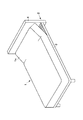
図1乃至図6はこの発明の第1の実施の形態を示す。図1はマットレス装置1をベッド2の床板3上に載置した状態を示す斜視図であって、このマットレス装置1は上記ベッド2のヘッドボード4側に位置する一端部1aを所定の角度で上昇させて保持することができるようになっている。
【0022】
上記マットレス装置1は、図2に示すようにクッション体としてのスプリングユニット5を有する。このスプリングユニット5は同図と図4(a)〜(c)に示すように鼓形状をなした多数のコイルスプリング6を行列状に配置することで、矩形板状をなしている。
【0023】
スプリングユニット6の長手方向に沿って隣り合うコイルスプリング6は幅方向に沿って設けられたヘリカル線7によって上端面と下端面とが連結されている。なお、図4(a)では上端面を連結したヘリカル線7だけを示している。
【0024】
上記スプリングユニット5の上下面の周縁部には枠線8が図示しないクリップによって取り付けられている。この枠線8はスプリングユニット5の幅方向両側の長手方向一端部で第1の部分8aと第2の部分8bとに分断されている。第1の部分8aと第2の部分8bとはそれぞれほぼコ字状となっている。それによって、スプリングユニット5は枠線8が分断された個所で折り曲げ可能となっている。
【0025】
なお、上記ヘリカル線7はスプリングユニット5の長手方向に沿って設けるようにしてもよい。また、枠線8の第1の部分8aと第2の部分8bとに分断された箇所は軟質な合成樹脂やゴムなどによって形成された部材、たとえば柱−部上の部材などによって連結するようにしてもよい。
【0026】
上記スプリングユニット5の外周部には、上記枠線8の第1の部分8aと対応するコ字状の固定杆状部材11と、同じく第2の部分8bに対応するコ字状の可動杆状部材12とが後述する保持手段によって上記スプリングユニット5と一体的に設けられている。
【0027】
上記固定杆状部材11と可動杆状部材12とはパイプ材によって形成されていて、これらの上記スプリングユニット5の一端部の両側に位置する両端は、それぞれヒンジ機構13によって回動可能かつ所定の回動角度で保持可能に連結されている。
【0028】
ヒンジ機構13によって連結された上記固定杆状部材11と可動杆状部材12とは、上記スプリングユニット5の平面形状よりもわずかに小さな矩形状をなしている。それによって、スプリングユニット5の外周部に設けられた固定杆状部材11と可動杆状部材12とは、図2と図3に示すようにスプリングユニット5の周辺部に位置するコイルスプリング6のばね部の軸方向中途部、この実施の形態では下端部の螺旋状の巻き線6a間に入り込み、このスプリングユニット6に一体的に保持されている。
【0029】
上記ヒンジ機構13は図6に示すように一端が枢軸16によって枢着された、取付け部としての第1のアーム17と第2のアーム18を有する。第1のアーム17の他端は上記可動杆状部材12の端部に嵌入固定され、第2のアーム18の端部は上記固定杆状部材11の端部に嵌入固定されている。
【0030】
第1のアーム17の一端には歯19が形成され、第2のアーム18の一端には上記歯18に係合するストッパ21がピン22によって枢支されている。このストッパ22はばね23によって上記歯19に係合する方向に付勢されている。
【0031】
上記枢軸16にはカム板24が回動可能に取付けられている。このカム板24の外周面には周方向に所定の角度で凹部25と凸部26とが形成されている。上記凸部26の上記枢軸16からの半径寸法は、上記歯19の枢軸16からの半径寸法よりも大きく形成されている。上記第1のアーム17の一端には、上記歯19に上記ストッパ21が係合した状態において、上記凹部25に位置する係合体27が設けられている。
【0032】
それによって、上記歯19と上記ストッパ21との係合によって第1のアーム17を第2のアーム18に対して所定の回動角度で保持することができる。上記第1のアーム17を図6に矢印で示す方向に回動させ、この回動にカム板24をその凹部25の一端に当接する係合体27によって連動させれば、このカム板34の凸部26に上記ストッパ21が乗り上げて歯19との係合が外れる。それによって、上記第1のアーム27を矢印と逆方向に自由に回動させることができる。
【0033】
上記第1のアーム17の矢印と逆方向の回動は上記係合体27が凹部25の他端に当接してカム板24を回動させ、上記ストッパ21がカム板24の凸部26から外れて歯29に係合するまで、すなわち第1のアーム17が第2のアーム18に対してほぼ水平な状態になるまで回動させることができる。
【0034】
したがって、上記可動杆状部材12は、上記ヒンジ機構13により、上記固定杆状部材11に対して所定の角度で起立した状態で保持可能であるとともに、起立した状態から水平に倒伏させることができるようになっている。
【0035】
図2と図5に示すように、上記スプリングユニット5の上下面の前面にはそれぞれフェルト31が設けられている。各フェルト31の周辺部は枠線8を巻き込むように折り曲げられ、その部分はクリップ32によって上記枠線8に保持されている。
【0036】
上記スプリングユニット5の下面に設けられたフェルト31には保持手段を構成する保持布33が設けられている。この保持布33はスプリングユニット5の平面形状よりも十分に大きな矩形状に形成されていて、周辺部がスプリングユニット5の周辺部から外方へ延出されている。
【0037】
上記保持布33のスプリングユニット5の周辺部から延出された周辺部は、図2と図3に示すようにスプリングユニット5の周辺部に設けられた固定杆状部材11と可動杆状部材12とにこれらの内周側から外周側に向かって巻かれ、スプリングユニット5の下面の周辺部に戻されている。
【0038】
図5に示すように、上記保持布33の各杆状部材11,12の内周側に向かう部分は第1のクリップ34によって上記フェルト31の端部とともに下側の枠線8に連結固定され、内周側から外周側に折り曲げられた部分は第2のクリップ35によって内周側の部分ととともに上記枠線8に連結固定されている。それによって、固定杆状部材11と可動杆状部材12とは、上記保持布33の周辺部よってスプリングユニット5に一体的に保持されている。
【0039】
固定杆状部材11と可動杆状部材12とがスプリングユニット5に一体的に保持されていることで、可動杆部12を固定杆部11に対して所定の角度で回動させれば、その回動にスプリングユニット5の可動杆状部材12に対応する部分を固定杆状部材11に対応する部分に対して所定の角度で屈曲させることができる。しかも、保持布33の周辺部が各杆状部材11,12に巻回されているとことで、各杆状部材11,12とコイルスプリング6とがぶつかり合って金属音が発生するが防止されている。
【0040】
さらに、固定杆状部材11と可動杆状部材12とは、スプリングユニット5の三方を囲むほぼコ字状となっている。そのため、スプリングユニット5は固定杆状部材11と可動杆状部材12戸によって幅方向に捩れるのが防止される。とくに、可動杆状部材12を上昇させてスプリングユニット5の一端部を上方へ屈曲させた場合、スプリングユニット5の屈曲された部分は幅方向に捩れ易くなるが、上記可動杆状部材12によって確実に防止することができる。
【0041】
なお、固定杆状部材11と可動杆状部材12とはスプリングユニット5の周辺部に位置するコイルスプリング6の巻き線6a間に係合している。そのため、保持布33を用いなくても、これら杆状部材11,12はスプリングユニット5に一体的に係合保持されるから、スプリングユニット5の可動杆部12に対応する一端部を、可動杆部材12の回動に連動させて折り曲げることは可能である。
【0042】
上記スプリングユニット5の上面のフェルト31と、下面の保持布33にはそれぞれウレタンフォームなどによって形成された弾性シート36が積層されている。この積層体は外装地37によって被覆されている。
【0043】
上記外装地37は、図2に示すように上記スプリングユニット5の上面を被覆した上部鏡地38と、下面を被覆した下部鏡地39及び外周面を被覆したまち地40とからなる。各鏡地38,39及びまち地40は表地と裏地との間に弾性シートを挟んだ3層構造となっていて、まち地40の上下端に各鏡地38,39の周辺部がテープエッジ41によって一体的に縫合されている。
【0044】
各鏡地38,39の裏地の周辺部には帯状のフランジ布42の幅方向一端が縫合されている。このフランジ布42は上記弾性シート36の周辺部を巻き込んで幅方向の他端をスプリングユニット5の周辺部に位置するコイルスプリング6の巻き線6aにクリップ43によって連結している。それによって、外装地37がスプリングユニット5に対してずれ動くのが防止されている。
【0045】
上記マットレス装置1によれば、スプリングユニット5の外周部に、固定杆状部材11と可動杆状部材12とを、コイルスプリング5の巻き線6a間に係合させて設け、これら杆状部材11,12を保持布33によって上記スプリングユニット5一体的に保持するようにした。上記固定杆状部材11と可動杆状部材12とはヒンジ機構13によって回動可能かつ所定の回動角度で保持可能に連結されている。
【0046】
そのため、上記可動杆状部材12を固定杆状部材11に対して図4(c)に実線で示す状態から鎖線で示すように上昇方向に回動させて所定の角度で保持すれば、この可動杆状部材12の回動にスプリングユニット5の上記可動杆状部材12に対応する一端部を鎖線で示すように連動させ、屈曲させることができる。
【0047】
スプリングユニット5の一端部を可動杆部材12によって屈曲させれば、図1に示すようにマットレス装置1の一端部1aを所定の角度で上昇させて保持することができる。
【0048】
それによって、図14(b)に示すように、マットレス装置1の上面に仰臥した利用者Uは頭部をわずかに持ち上げた姿勢を楽に維持することができるから、仰臥した状態で読書をしたり、テレビを見るなどのことができる。
【0049】
図14(a)に示すように利用者Uがマットレス装置1上で枕44を用いて横臥する場合、このマットレス装置1の一端部1aを上昇させれば、その角度によって頭部が脊柱に対して左右に曲がることがない姿勢をとることができるから、首に負担をかけることなく横臥の姿勢を楽に維持することができる。
【0050】
このように、マットレス装置1の一端部1aを、可動杆状部材12によって所定の角度で上昇させて保持することができるようにした。そのため、マットレス装置1の一端部を上昇させるために、ベッド2の床板3を起伏用の駆動機構によって起伏させる場合に比べ、簡単で、安価な構成とすることができる。
【0051】
また、マットレス装置1は、スプリングユニット5が外装地37で被覆されており、しかもスプリングユニット5の一端部を屈曲させるための固定杆状部材11、可動杆上部材12或いはヒンジ機構13が外観的には全く見えない。しかも、各管状部材11,12はスプリングユニット5の周辺部に位置するコイルスプリング6の巻き線6a間に挿入されているから、マットレス装置1の周辺部から外部に突出するということもない。
【0052】
そのため、このマットレス装置1は、一端部が折り曲げることができるようになっているにも係わらず、外観的には通常のマットレス装置となんら変わるところがないから、極めて体裁がよいばかりか、上下面のどちらの面を上にしてでも使用することができる。
【0053】
図7は第1の実施の形態の固定杆状部材11と可動杆状部材12との変形例を示す第2の実施の形態である。この実施の形態では、固定杆状部材11と可動杆状部材12とがそれぞれ一対の直杆11a,12aからなる。これらの直杆11a,12aは端部がヒンジ機構13によって連結されている。そして、連結された各直杆11a,12aはスプリングユニット5の幅方向両側に位置するコイルスプリング6の巻き線6a間に係合させて設けられている。
【0054】
上記スプリングユニット5の幅方向両側に位置する各一対の直杆11a,12aは、それぞれ丸棒などの保持手段としての連結部材45によって連結され、スプリングユニット5に一体的に保持されている。
【0055】
したがって、このような構成であっても、可動杆状部材12の一対の直杆12aを、固定杆状部材11の一対の直杆11aに対してヒンジ機構13により、所定の角度に回動上昇させれば、スプリングユニット5の上記可動杆状部材12の一対の直杆12aに対応する部分を、これら直杆12aに連動させて屈曲上昇させることができる。つまり、固定杆状部材11と可動杆状部材12とはコ字状でなく、直杆状であってもよい。
【0056】
なお、保持手段としては、上記各直杆11a,12aをスプリングユニット5の周辺部に位置するコイルスプリング6の巻き線6aに結束するワイヤや紐などの結束部材であってもよい。
【0057】
図8乃至図10はこの発明の第3の実施の形態を示す。この実施の形態のマットレス装置1Aは、クッション性能を向上させるためにダブルククッションタイプとなっている。すなわち、マットレス装置1Aは、図9に示すように第1の実施の形態と同じ構成のスプリングユニット5を有し、このスプリングユニット5はボトムクッション体としてのボトムスプリングユニット51の上面にフェルトなどのシート状の仕切り部材52を介して積層されている。仕切り部材52は各スプリングユニット5,51の長手方向一端部、つまりスプリングユニット5の可動杆状部材12に対応する部分を除く部分に設けられている。
【0058】
上記ボトムスプリングユニット51は、多数のコイルスプリング53を行列状に配置し、長手方向において隣り合うコイルスプリング53の上下端面を長手方向と交差する幅方向に沿ってヘリカル線(図示せず)によって連結するととともに、下面の周縁部に枠線54を設けて構成されている。
【0059】
上記スプリングユニット5の下面周縁部に設けられた枠線8は、ボトムスプリングユニット51の上面周縁部の枠線を兼ねているとともに、上記第1の実施の形態のように2つの部分8a,8bに分断されている。
【0060】
上記スプリングユニット5の下側の枠線8の一方の部分8aには、ボトムスプリングユニット51の周辺部に位置するコイルスプリング53の上端面が仕切り部材52の周縁部とともにクリップ(図示せず)によって一体的に結合されている。
【0061】
ボトムスプリングユニット51の下面にはシート状の下部弾性シート56が積層され、スプリングユニット5の上面には上部弾性シート57が積層されている。そして、この積層体は外装地58によって被覆されている。
【0062】
積層された2つのスプリングユニット5,51の長手方向の一端部である、スプリングユニット5の可動杆状部材12によって屈曲される部分は、上記外装地58が上側のスプリングユニット5と下側のボトムスプリングユニット51とを別々に被覆している。すなわち、積層体の一端部においては、スプリングユニット5は外装地58によって上面だけでなく下面も被覆され、ボトムスプリングユニット51は下面だけでなく、上面も被覆されている。
【0063】
したがって、このような構成によれば、図8に示すように、マットレス装置1Aの一端部1aを所定の角度で上昇させて保持することができる。そして、そのときマットレス装置1Aの一端部1aに位置するスプリングユニット5とボトムスプリングユニット51は外装地58によって別々に被覆されているから、スプリングユニット5の下面やボトムスプリングユニット51の上面が外部に全く露出しないので、外観的に極めて体裁がよい。
【0064】
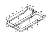
図11と図12はこの発明の第4の実施の形態を示すマットレス装置1Bの変形例である。この実施の形態のマットレス装置1Bは、第1の実施の形態に示す2つのスプリングユニット5を幅方向に並設し、これらスプリングユニット5を外装地61で被覆して構成されている。つまり、マットレス装置1Bはダブルサイズとなっている。
【0065】
2つのスプリングユニット5の可動杆状部材12によって屈曲される、マットレス装置1Bの一対の一端部1bは、それぞれの部分を独立して屈曲させることができるよう、上記外装地61によって別々に被覆されている。
【0066】
それによって、マットレス装置1Bの一対の一端部1bのうち、どちらか一方の一端部1bだけを選択的に回動上昇させることができるばかりか、一方の一端部1bだけを回動上昇させたときに、その一端部1bや他方の一端部1bの内部構造、つまりスプリングユニット5が外部に露出することがないから、外観的にも体裁がよい。
【0067】
図13(a)〜(c)はこの発明の第5の実施の形態を示す、スプリングユニットの変形例である。図13(a)に示すスプリングユニット5Aは、その長手方向の一端部と他端部とがそれぞれ可動杆状部材12によって屈曲させることができるようになっている。
【0068】
すなわち、固定杆状部材11Aは直杆状をなしていて、その一端と他端とにそれぞれコ字状の可動杆状部材12がヒンジ機構13によって回動可能かつ所定の回動角度で保持可能に連結されている。一方の可動杆状部材12と他方の可動杆状部材12とは、同図に矢印で示すように互いに逆方向に回動するよう、ヒンジ機構13の向きが上下逆方向になっている。
【0069】
なお、枠線8は直杆状の固定杆状部材11Aの両端部に対応する箇所でそれぞれ分断されており、枠線8が各可動杆状部材12によってスプリングユニット5の両端部を屈曲させる際に邪魔になることがないようになっている。
【0070】
このように、スプリングユニット5Aの一端部と他端部とを逆方向に屈曲させることができることで、スプリングユニット5Aの一方の面と他方の面とのどちらの面を上にして利用する場合であっても、その一端部を上方へ屈曲させて利用者の頭部を持ち上げて保持することができる。
【0071】
図13(b)は第1の実施の形態のスプリングユニットの変形例であって、この実施の形態のスプリングユニット5Bは一端部が二段階に屈曲させることができるようになっている。すなわち、スプリングユニット5Bの外周部に設けられる可動杆状部材12は、スプリングユニット5Bの両側に位置する中途部が複数の部分、この実施の形態では2つの部分12x,12y分断されている。
【0072】
分断された2つの部分12x,12yは、上記固定杆状部材11の端部に順次ヒンジ機構13によって連結されている。これらのヒンジ機構13は、可動杆状部材12の2つの部分12x,12yを同方向に屈曲させるように設けられている。
【0073】
したがって、図14(c)に示すように、このような構成のスプリングユニット5Bを用いたマットレス装置1Cによれば、可動杆状部材12の2つの部分12x,12yをそれぞれ上昇方向に屈曲させることで、利用者Uの頭部だけでなく、上半身を起こした状態で保持することが可能となる。
【0074】
図13(c)に示すスプリングユニット5Cは図13(a)と図13(b)とを組み合わせた構成となっている。すなわち、スプリングユニット5Cの両端部がそれぞれ可動杆状部材12によって逆方向に屈曲させることができるようになっているとともに、一方の可動杆状部材12は2つの部分12x,12yからなり、その2つの部分12x,12yはヒンジ機構13によって同方向に屈曲可能となっている。なお、枠線8は、それぞれのヒンジ機構13,13Aに対応する部分で分断されている。
【0075】
したがって、このような構成のスプリングユニット5Cによれば、同図に鎖線で示すように屈曲させることが可能となるから、利用者の上半身を起こすとともに、脚部を屈曲させた状態とすることができる。
【0076】
すなわち、従来は床板を背上げ駆動機構によって起伏させることによって行なっていた動作を、マットレス装置を構成するスプリングユニット5Cによって行なうことが可能となる。
【0077】
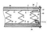
図15はこの発明の第6の実施の形態を示す。この実施の形態はスプリングユニットを構成するばね体の変形例である。すなわち、スプリングユニット5Dを構成するばね体にはコイルスプリングに代わり連続ばね61が用いられている。この連続ばね61は複数のコイル部62を有する。複数のコイル部62は、1本の線材によって軸線をほぼ平行にしている。隣り合う一対のコイル部62は、中途部の巻き線が係合しているとともに、上端は上部連結杆63によって連続され、下端は下部連結杆64によって連続されている。
【0078】
並設された複数の連続ばね61は、並設方向と交差する方向に沿って設けられたヘリカル線65によって連結されている。このスプリングユニット5Dの上下面の周縁部には、上記第1の実施の形態と同様、枠線8がクリップ66によって取付けられている。枠線8は、詳細は図示しないが、ヒンジ機構13によって連結された固定杆部材11と可動杆部材12との連結部分に対応する箇所で分断されている。
【0079】
図15はスプリングユニット5Dを下面側から見た図で、可動杆状部材12が設けられた端部はヒンジ機構13によって同図で矢印で示す方向に屈曲される。
【0080】
上記固定杆状部材11と可動杆状部材12とはスプリングユニット5Dの周辺部に位置するコイル部62の巻き線間に挿入されて第1の実施の形態と同様な保持手段によって保持される。
【0081】
したがって、スプリングユニット5Dがコイルスプリング以外のばね体である、連続ばね61によって構成されていても、そのスプリングユニット5Dの一端部を可動杆状部材上昇方向に屈曲させることが可能である。
【0082】
図16と図17はこの発明の第7の実施の形態を示す。この実施の形態のマットレス装置1Cは、クッション体として上記各実施の形態に示されたスプリングユニットに代わり、軟質或いは半硬質の発泡弾性体71によって形成されている。この発泡弾性体71は矩形板状に成形されていて、その外周面には全長にわたって保持手段を構成する保持溝72が形成されている。
【0083】
上記保持溝72にはパイプ材をコ字状に曲成した固定杆状部材11と可動杆状部材12とが弾性的に圧入保持されている。固定杆状部材11と可動杆状部材12との両端部はそれぞれヒンジ機構13によって回動可能かつ所定の回動角度で保持可能に連結されている。そして、上記発泡弾性体71は外装地73によって被覆されている。
【0084】
このような構成のマットレス装置1Cによれば、可動杆状部材12を固定杆状部材11に対してヒンジ機構13によって所定の回動角度で屈曲させれば、発泡弾性体71の可動杆状部材12に対応する部分が、可動杆状部材12と保持溝72との係合によって弾性的に屈曲させられる。したがって、マットレス装置1Cの一端部を図17に鎖線で示すように屈曲させることができる。
【0085】
すなわち、クッション体としてはスプリングユニットでなく、発泡弾性体であっても、この発明を適用することができる。
【0086】
なお、上記各実施の形態において、クッション体がスプリングユニットの場合、固定杆状部材と可動杆状部材とをウレタンフォームなどの樹脂シートで被覆したり、発泡樹脂を吹き付けるようにしてもよく、そのような構成によれば、各管状部材とスプリングユニットのばね体とがぶつかり合って騒音を発生するのを防止することができる。
【0087】
【発明の効果】
以上のようにこの発明によれば、可動杆状部材を所定の角度で起立させれば、この可動杆状部材によってクッション体の少なくとも利用者の頭部が載置された部分を屈曲させることができるから、それによって利用者の頭部を持ち上げて保持することができる。
【0088】
すなわち、従来のようにベッドの床板を起伏駆動機構を用いて起伏させなくても、マットレス装置の少なくとも一端部を起伏せることができるため、コスト的に有利である。
【図面の簡単な説明】
【図1】この発明の第1の実施の形態に係るマットレス装置が用いられたベッドの斜視図。
【図2】マットレス装置の一部分を示す断面図。
【図3】固定杆状部材と可動杆状部材とをスプリングユニットに保持する手段を拡大して示した断面図。
【図4】(a)はスプリングユニットの概略的構成を示す斜視図、(b)はスプリングユニットの側面図、(c)はスプリングユニットの正面図。
【図5】固定杆状部材と可動杆状部材とをスプリングユニットに保持する構造を一部破断して示す斜視図。
【図6】ヒンジ機構の一部断面した側面図。
【図7】この発明の第2の実施の形態を示すスプリングユニットの概略的構成を示す斜視図。
【図8】この発明の第3の実施の形態に係るマットレス装置が用いられたベッドの斜視図。
【図9】図8に示すマットレス装置の断面図。
【図10】図9に示すマットレス装置に用いられたスプリングユニットの斜視図。
【図11】この発明の第4の実施の形態に係るマットレス装置が用いられたベッドの斜視図。
【図12】図11に示すマットレス装置に用いられたスプリングユニットの斜視図。
【図13】(a)〜(c)はそれぞれこの発明の第5の実施の形態を示すスプリングユニットの側面図。
【図14】この発明のマットレス装置の使用形態の説明図。
【図15】この発明の第6の実施の形態を示すスプリングユニットの一部分を示す斜視図。
【図16】この発明の第7の実施の形態を示すマットレス装置の一部破断した斜視図。
【図17】図16に示すマットレス装置の側面図。
【符号の説明】
5…スプリングユニット、6…コイルスプリング、11…固定杆状部材、12…可動杆上部材、13…ヒンジ機構、17…第1のアーム、18…第2のアーム、33…保持布(保持手段)、37…外装地、45…紐状部材(保持手段)、71…発泡弾性体、72…保持溝(保持手段)。[0001]
BACKGROUND OF THE INVENTION
The present invention relates to a mattress device used for a bed or the like.
[0002]
[Prior art]
For example, a mattress device used for a bed has a cushion body such as a spring unit or a foamed elastic body formed in a rectangular plate shape, and is configured by covering the cushion body with an exterior ground.
[0003]
A user who is supine on the top surface of the mattress device may read a book or watch television in a supine posture. In that case, it is easier to read or watch TV when the head is slightly lifted than when it is level.
[0004]
In the conventional mattress device, since the user's head cannot be held up, in order for the user to raise the head, the cushion is folded under the pillow and sandwiched. . However, if the head is lifted in such a manner, the stability is poor and it may be easy to get tired.
[0005]
[Problems to be solved by the invention]
As a bed in which a mattress device is used, a so-called wake-up bed is known in which a floor board on which the mattress device is placed is divided into a plurality of portions so that a portion corresponding to the upper body of the user can be driven up and down. According to the wake-up bed, it is possible to raise the user's upper body by raising a part of the floor board.
[0006]
However, in the case of a wake-up bed, a drive mechanism is required to drive a part of the floor plate up and down. Therefore, in order to incorporate this drive mechanism into the bed, the configuration is complicated and the cost is increased, and the bed is enlarged. May be invited.
[0007]
An object of the present invention is to provide a mattress device that can lift at least a user's head with a simple structure.
[0008]
[Means for Solving the Problems]
This invention is a mattress device used by a user by positioning the head on the upper surface of one end in the longitudinal direction.
A foldable cushion body,
A fixed hook-shaped member integrally provided on at least both sides of the outer periphery of the cushion body;
A hinge mechanism having a pair of attachment portions coupled so as to be rotatable and capable of being held at a predetermined rotation angle, wherein one attachment portion is attached to an end of the fixed rod-shaped member;
A movable rod connected to the other mounting portion of the hinge mechanism and integrally provided on an outer peripheral portion of at least one end portion of the cushion body, and bent at least one end portion of the cushion body by being rotated and raised by the hinge mechanism. A member,
Has an exterior covering the cushion bodyAnd
The cushion body is a spring unit, and the fixed hook-shaped member and the movable hook-shaped member are integrally held by a holding means on a coil portion of a spring body located on an outer peripheral portion of the spring unit,
The holding means is a holding cloth provided on the lower surface or the upper surface of the spring unit with a peripheral portion extending from the peripheral portion of the spring unit, and the peripheral portion of the holding means has the fixed hook-shaped member and the movable member. It is wound around the bowl-shaped member, and the winding portion is connected and fixed to the periphery of the spring unit with a clip.The mattress device is characterized by that.
[0009]
It is preferable that the fixed hook-shaped member and the movable hook-shaped member are substantially U-shaped, and both end portions located on one end side on both sides of the cushion body are connected by the hinge mechanism.
[0010]
The fixed hook-shaped member has a straight hook shape provided on both sides of the cushion body, and the movable hook-shaped member can be rotated in opposite directions by the hinge mechanism at both ends of the fixed hook-shaped member. It is preferable that it is connected.
[0011]
It is preferable that the movable hook-shaped member has a plurality of parts, and the plurality of parts are sequentially connected to the fixed hook-shaped member by a hinge mechanism.
[0018]
The fixed hook-shaped member and the movable hook-shaped member connected by the hinge mechanism have a rectangular frame shape smaller than the planar shape of the spring unit, and these hook-shaped members are located in the periphery of the spring unit. It is preferably inserted and held between the windings of the coil portion of the spring body.
[0019]
According to this invention, if the movable hook-shaped member is raised at a predetermined angle, the movable hook-shaped member can bend at least a portion of the cushion body on which the user's head is placed. This makes it possible to lift and hold the user's head.
[0020]
DETAILED DESCRIPTION OF THE INVENTION
Embodiments of the present invention will be described below with reference to the drawings.
[0021]
1 to 6 show a first embodiment of the present invention. FIG. 1 is a perspective view showing a state in which a
[0022]
The
[0023]
The
[0024]
A
[0025]
The
[0026]
On the outer periphery of the
[0027]
The fixed hook-shaped
[0028]
The fixed hook-shaped
[0029]
As shown in FIG. 6, the
[0030]
A
[0031]
A
[0032]
Accordingly, the
[0033]
When the
[0034]
Therefore, the movable hook-shaped
[0035]
As shown in FIGS. 2 and 5, felts 31 are provided on the front surfaces of the upper and lower surfaces of the
[0036]
The felt 31 provided on the lower surface of the
[0037]
The peripheral part of the holding
[0038]
As shown in FIG. 5, the portion of the holding
[0039]
If the fixed hook-shaped
[0040]
Furthermore, the fixed hook-shaped
[0041]
The fixed hook-shaped
[0042]
[0043]
As shown in FIG. 2, the
[0044]
One end in the width direction of the belt-
[0045]
According to the
[0046]
Therefore, if the movable hook-
[0047]
If one end portion of the
[0048]
Thereby, as shown in FIG. 14 (b), the user U who is supine on the upper surface of the
[0049]
When the user U lies on the
[0050]
As described above, the one
[0051]
Further, in the
[0052]
Therefore, the
[0053]
FIG. 7 is a second embodiment showing a modification of the fixed hook-shaped
[0054]
The pair of
[0055]
Therefore, even in such a configuration, the pair of
[0056]
The holding means may be a binding member such as a wire or string that binds the
[0057]
8 to 10 show a third embodiment of the present invention. The
[0058]
The
[0059]
The
[0060]
In one
[0061]
A sheet-like lower
[0062]
The portion bent by the movable hook-
[0063]
Therefore, according to such a configuration, as shown in FIG. 8, the one
[0064]
FIG. 11 and FIG. 12 show a modification of the
[0065]
The pair of one
[0066]
Thereby, not only one
[0067]
FIGS. 13A to 13C are modifications of the spring unit showing the fifth embodiment of the present invention. The
[0068]
That is, the fixed rod-shaped
[0069]
The
[0070]
In this way, one end and the other end of the
[0071]
FIG. 13B is a modification of the spring unit of the first embodiment, and the
[0072]
The two divided
[0073]
Therefore, as shown in FIG. 14 (c), according to the
[0074]
The spring unit 5C shown in FIG. 13C has a configuration combining FIG. 13A and FIG. 13B. That is, both end portions of the spring unit 5C can be bent in opposite directions by the movable hook-shaped
[0075]
Therefore, according to the spring unit 5C having such a configuration, it is possible to bend as shown by a chain line in the figure, so that the upper body of the user is raised and the leg is bent. it can.
[0076]
In other words, the operation conventionally performed by raising and lowering the floor board by the back-up drive mechanism can be performed by the spring unit 5C constituting the mattress device.
[0077]
FIG. 15 shows a sixth embodiment of the present invention. This embodiment is a modification of the spring body constituting the spring unit. That is, a
[0078]
The plurality of
[0079]
FIG. 15 is a view of the spring unit 5D as viewed from the lower surface side, and the end provided with the movable hook-
[0080]
The fixed hook-
[0081]
Therefore, even if the spring unit 5D is constituted by the
[0082]
16 and 17 show a seventh embodiment of the present invention. The
[0083]
The holding
[0084]
According to the
[0085]
That is, the present invention can be applied even if the cushion body is not a spring unit but a foamed elastic body.
[0086]
In each of the above embodiments, when the cushion body is a spring unit, the fixed hook-shaped member and the movable hook-shaped member may be covered with a resin sheet such as urethane foam, or foamed resin may be sprayed. According to such a structure, it can prevent that each tubular member and the spring body of a spring unit collide, and generate | occur | produce a noise.
[0087]
【The invention's effect】
As described above, according to the present invention, when the movable hook-shaped member is raised at a predetermined angle, at least a portion of the cushion body where the user's head is placed can be bent by the movable hook-shaped member. Because it can, it can lift and hold the user's head.
[0088]
That is, it is advantageous in terms of cost because at least one end portion of the mattress device can be raised and lowered without raising and lowering the floor plate of the bed using the raising and lowering drive mechanism as in the prior art.
[Brief description of the drawings]
FIG. 1 is a perspective view of a bed in which a mattress device according to a first embodiment of the present invention is used.
FIG. 2 is a cross-sectional view showing a part of the mattress device.
FIG. 3 is an enlarged cross-sectional view showing a means for holding a fixed hook-shaped member and a movable hook-shaped member on a spring unit.
4A is a perspective view showing a schematic configuration of a spring unit, FIG. 4B is a side view of the spring unit, and FIG. 4C is a front view of the spring unit.
FIG. 5 is a partially cutaway perspective view showing a structure in which a fixed hook-shaped member and a movable hook-shaped member are held by a spring unit.
FIG. 6 is a partial cross-sectional side view of the hinge mechanism.
FIG. 7 is a perspective view showing a schematic configuration of a spring unit showing a second embodiment of the invention.
FIG. 8 is a perspective view of a bed in which a mattress device according to a third embodiment of the present invention is used.
9 is a cross-sectional view of the mattress device shown in FIG.
10 is a perspective view of a spring unit used in the mattress device shown in FIG. 9. FIG.
FIG. 11 is a perspective view of a bed in which a mattress device according to a fourth embodiment of the present invention is used.
12 is a perspective view of a spring unit used in the mattress device shown in FIG.
FIGS. 13A to 13C are side views of a spring unit showing a fifth embodiment of the present invention. FIG.
FIG. 14 is an explanatory diagram of a usage pattern of the mattress device of the present invention.
FIG. 15 is a perspective view showing a part of a spring unit showing a sixth embodiment of the invention.
FIG. 16 is a partially cutaway perspective view of a mattress device showing a seventh embodiment of the present invention.
17 is a side view of the mattress device shown in FIG. 16. FIG.
[Explanation of symbols]
DESCRIPTION OF
Claims (5)
折り曲げ可能なクッション体と、
このクッション体の外周部の少なくとも両側に一体的に設けられた固定杆状部材と、
回動可能かつ所定の回動角度で保持可能に連結された一対の取付け部を有し、一方の取付け部が上記固定杆状部材の端部に取付けられたヒンジ機構と、
このヒンジ機構の他方の取付け部に連結されて上記クッション体の少なくとも一端部の外周部に一体的に設けられ上記ヒンジ機構によって回動上昇させることで上記クッション体の少なくとも一端部を屈曲させる可動杆状部材と、
上記クッション体を被覆した外装地を具備し、
上記クッション体はスプリングユニットであって、上記固定杆状部材と上記可動杆状部材とは、上記スプリングユニットの外周部に位置するばね体のコイル部に保持手段によって一体的に保持され、
上記保持手段は、上記スプリングユニットの下面若しくは上面に周辺部を上記スプリングユニットの周辺部から延出させて設けられた保持布であって、この保持布は周辺部が上記固定杆状部材及び可動杆状部材に巻回されるとともに、その巻回部分が上記スプリングユニットの周辺部にクリップで連結固定されていることを特徴とするマットレス装置。In the mattress device used by the user by positioning the head on the upper surface of one end in the longitudinal direction,
A foldable cushion body,
A fixed hook-shaped member integrally provided on at least both sides of the outer periphery of the cushion body;
A hinge mechanism having a pair of attachment portions coupled so as to be rotatable and capable of being held at a predetermined rotation angle, wherein one attachment portion is attached to an end of the fixed rod-shaped member;
A movable rod connected to the other mounting portion of the hinge mechanism and integrally provided on an outer peripheral portion of at least one end portion of the cushion body, and bent at least one end portion of the cushion body by being rotated and raised by the hinge mechanism. A member,
Comprising an exterior covering the cushion body ,
The cushion body is a spring unit, and the fixed hook-shaped member and the movable hook-shaped member are integrally held by a holding means on a coil portion of a spring body located on an outer peripheral portion of the spring unit,
The holding means is a holding cloth provided on the lower surface or the upper surface of the spring unit with a peripheral portion extending from the peripheral portion of the spring unit, and the peripheral portion of the holding means has the fixed hook-shaped member and the movable member. A mattress device, wherein the mattress device is wound around a bowl-shaped member, and the winding portion is connected and fixed to a peripheral portion of the spring unit with a clip .
Priority Applications (4)
| Application Number | Priority Date | Filing Date | Title |
|---|---|---|---|
| JP2003028758A JP4160837B2 (en) | 2003-02-05 | 2003-02-05 | Mattress equipment |
| DE112004000255T DE112004000255T5 (en) | 2003-02-05 | 2004-01-21 | The mattress apparatus |
| PCT/JP2004/000490 WO2004069007A1 (en) | 2003-02-05 | 2004-01-21 | Mattress device |
| US11/192,658 US7152262B2 (en) | 2003-02-05 | 2005-07-29 | Mattress apparatus |
Applications Claiming Priority (1)
| Application Number | Priority Date | Filing Date | Title |
|---|---|---|---|
| JP2003028758A JP4160837B2 (en) | 2003-02-05 | 2003-02-05 | Mattress equipment |
Publications (2)
| Publication Number | Publication Date |
|---|---|
| JP2004261214A JP2004261214A (en) | 2004-09-24 |
| JP4160837B2 true JP4160837B2 (en) | 2008-10-08 |
Family
ID=33112018
Family Applications (1)
| Application Number | Title | Priority Date | Filing Date |
|---|---|---|---|
| JP2003028758A Expired - Fee Related JP4160837B2 (en) | 2003-02-05 | 2003-02-05 | Mattress equipment |
Country Status (1)
| Country | Link |
|---|---|
| JP (1) | JP4160837B2 (en) |
Families Citing this family (3)
| Publication number | Priority date | Publication date | Assignee | Title |
|---|---|---|---|---|
| JP4892279B2 (en) * | 2006-05-09 | 2012-03-07 | フランスベッド株式会社 | Mattress equipment |
| KR101152597B1 (en) * | 2009-03-11 | 2012-06-04 | 오주민 | Coil spring mattress for bed |
| US8266746B2 (en) * | 2010-04-07 | 2012-09-18 | Zinus, Inc. | Self-adjusting mattress with balancing bars and an integrated movement mechanism |
-
2003
- 2003-02-05 JP JP2003028758A patent/JP4160837B2/en not_active Expired - Fee Related
Also Published As
| Publication number | Publication date |
|---|---|
| JP2004261214A (en) | 2004-09-24 |
Similar Documents
| Publication | Publication Date | Title |
|---|---|---|
| US7152262B2 (en) | Mattress apparatus | |
| US7487564B2 (en) | Articulatable spring mechanisms for items of furniture | |
| US8806672B1 (en) | Foldable sofa mattress and method | |
| JP4160837B2 (en) | Mattress equipment | |
| JP4160845B2 (en) | Mattress equipment | |
| JP3009349B2 (en) | Spring structure | |
| JP2003052489A (en) | Seat backrest device | |
| JP3009348B2 (en) | Spring structure | |
| JP2005168688A (en) | Mattress apparatus | |
| JP3505350B2 (en) | Mattress equipment | |
| JP2941165B2 (en) | Sofa-bed | |
| JP4892279B2 (en) | Mattress equipment | |
| JPH0144110Y2 (en) | ||
| JP2002209668A (en) | Sunshade for chair | |
| JP3579213B2 (en) | Mattress equipment | |
| JPH038122Y2 (en) | ||
| JP4376580B2 (en) | Reclining mattress device and bed device | |
| JPH0415084Y2 (en) | ||
| JPH06296534A (en) | Device for mattress | |
| JPS6015475Y2 (en) | Bed chair | |
| JP2023184434A (en) | Elastic cushion, elastic cushion assembling method and furniture | |
| JPH0655457U (en) | Soft Urbet | |
| JP3168248B2 (en) | Spring structure | |
| JPH0443092Y2 (en) | ||
| JP3045963U (en) | Folding bed chair |
Legal Events
| Date | Code | Title | Description |
|---|---|---|---|
| A621 | Written request for application examination |
Free format text: JAPANESE INTERMEDIATE CODE: A621 Effective date: 20051202 |
|
| A131 | Notification of reasons for refusal |
Free format text: JAPANESE INTERMEDIATE CODE: A131 Effective date: 20080415 |
|
| A521 | Request for written amendment filed |
Free format text: JAPANESE INTERMEDIATE CODE: A523 Effective date: 20080612 |
|
| TRDD | Decision of grant or rejection written | ||
| A01 | Written decision to grant a patent or to grant a registration (utility model) |
Free format text: JAPANESE INTERMEDIATE CODE: A01 Effective date: 20080708 |
|
| A01 | Written decision to grant a patent or to grant a registration (utility model) |
Free format text: JAPANESE INTERMEDIATE CODE: A01 |
|
| A61 | First payment of annual fees (during grant procedure) |
Free format text: JAPANESE INTERMEDIATE CODE: A61 Effective date: 20080718 |
|
| R150 | Certificate of patent or registration of utility model |
Ref document number: 4160837 Country of ref document: JP Free format text: JAPANESE INTERMEDIATE CODE: R150 Free format text: JAPANESE INTERMEDIATE CODE: R150 |
|
| FPAY | Renewal fee payment (event date is renewal date of database) |
Free format text: PAYMENT UNTIL: 20110725 Year of fee payment: 3 |
|
| FPAY | Renewal fee payment (event date is renewal date of database) |
Free format text: PAYMENT UNTIL: 20120725 Year of fee payment: 4 |
|
| FPAY | Renewal fee payment (event date is renewal date of database) |
Free format text: PAYMENT UNTIL: 20120725 Year of fee payment: 4 |
|
| FPAY | Renewal fee payment (event date is renewal date of database) |
Free format text: PAYMENT UNTIL: 20130725 Year of fee payment: 5 |
|
| FPAY | Renewal fee payment (event date is renewal date of database) |
Free format text: PAYMENT UNTIL: 20130725 Year of fee payment: 5 |
|
| FPAY | Renewal fee payment (event date is renewal date of database) |
Free format text: PAYMENT UNTIL: 20140725 Year of fee payment: 6 |
|
| FPAY | Renewal fee payment (event date is renewal date of database) |
Free format text: PAYMENT UNTIL: 20150725 Year of fee payment: 7 |
|
| LAPS | Cancellation because of no payment of annual fees |