JP4158421B2 - Inkjet head precursor and inkjet head - Google Patents
Inkjet head precursor and inkjet head Download PDFInfo
- Publication number
- JP4158421B2 JP4158421B2 JP2002162349A JP2002162349A JP4158421B2 JP 4158421 B2 JP4158421 B2 JP 4158421B2 JP 2002162349 A JP2002162349 A JP 2002162349A JP 2002162349 A JP2002162349 A JP 2002162349A JP 4158421 B2 JP4158421 B2 JP 4158421B2
- Authority
- JP
- Japan
- Prior art keywords
- reference hole
- flat plate
- precursor
- ink
- inkjet head
- Prior art date
- Legal status (The legal status is an assumption and is not a legal conclusion. Google has not performed a legal analysis and makes no representation as to the accuracy of the status listed.)
- Expired - Fee Related
Links
Images


Landscapes
- Particle Formation And Scattering Control In Inkjet Printers (AREA)
Description
【0001】
【発明の属する技術分野】
本発明は、インクを印字面に噴射することで所望の画像を形成するインクジェット記録装置のインクジェットヘッドの前躯体およびインクジェットヘッドの構成に関する。
【0002】
【従来の技術】
従来から、エッチング等で予め空間を形成してある複数枚の薄い平板を複数枚積層・接着することで、前記の空間同士を接続し、マニホールド流路や圧力室やノズルなどのインク流路を内部に形成する構成としたインクジェットヘッドの技術は公知となっている。
【0003】
【発明が解決しようとする課題】
ここでインクジェット記録装置に対する高解像度化・高画質化といった近時の要請に対応すべく、前述のインク流路の複雑化・高集積化が進んでおり、この観点からは、インクジェットヘッドを構成する平板同士を位置ズレなく高精度で位置決めして貼り合わせることが必要になる。
即ち、貼り合わせる際に位置ズレがあると、インク流路が平板のズレた継ぎ目の部分で狭窄される結果となり、当該部分で意図せぬ流路抵抗が生じたり、流路が詰まってインクが噴射不可能となったりする弊害がある。
【0004】
この点、貼り合わせる際に互いの平板の位置を画像処理などにより算出して位置合わせをする方法もあるが、この方法では画像処理装置などの設備コストが掛かってしまい、コストの増大要因となってしまう。
【0005】
本発明は以上の点に鑑みてされたものであり、その目的は、簡素な構成で平板同士を正確に位置決めして積層接着することができるインクジェットヘッドの前躯体およびインクジェットヘッドの構成を提供することにある。
【0006】
【課題を解決するための手段】
本発明の解決しようとする課題は以上の如くであり、次にこの課題を解決するための手段を説明する。
【0007】
即ち、請求項1においては、複数枚の金属製の平板を積層して、内部にインクが供給されるインク供給口からインクが噴射されるノズルに至る流路が形成されたインクジェットヘッドの前躯体であって、前記複数枚の平板のそれぞれは、積層して前記流路が形成される本体部分と、積層するときに前記本体部分の相互位置を一致させる基準孔が貫通状に形成された桟の部分とを一体的に有し、それぞれの基準孔は、その板厚方向中間部が窄まった形状に構成されており、その最も窄まった部分の径が当該基準孔に挿入される位置決め棒の径よりも小さいものである。
【0008】
請求項2及び8においては、それぞれの平板に形成されている前記基準孔は、当該平板の両側の面からエッチングを施すことにより形成されているものである。
請求項3においては、前記基準孔は、前記エッチングによって形成された球面状の窪み同士が連通して構成されているものである。
【0009】
請求項4及び9においては、前記基準孔は円形の孔に構成されるとともに、その円形の円周上の一部において半径方向の切り込みが形成されているものである。
【0010】
請求項5においては、前記半径方向の切り込みは、前記基準孔の周方向に等間隔をおいて複数形成されているものである。
【0011】
請求項6及び10においては、それぞれの平板に設けられている前記基準孔は、その最も窄まった部分と当該平板の一側の面との距離をh、当該平板の板厚をtとしたときに、0.25t≦h≦0.75tの条件を満たすものである。
請求項7においては、複数枚の金属製の平板を積層して、内部にインクが供給されるインク供給口からインクが噴射されるノズルに至る流路が形成されたインクジェットヘッドであって、前記複数枚の平板のそれぞれは、積層して前記流路を形成するときに前記平板の相互位置を一致させるために形成された基準孔を有し、それぞれの基準孔は、その板厚方向中間部が窄まった形状に構成されており、その最も窄まった部分の径が当該基準孔に挿入される位置決め棒の径よりも小さいものである。
【0012】
【発明の実施の形態】
次に、発明の実施の形態を説明する。
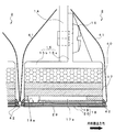
図1は本発明の一実施形態に係るインクジェット記録装置(インクジェットプリンタ)の全体的な構成を示した側面図である。
図2はインクジェットヘッドが並べて設けられた状態を示す底面図、図3はインクジェットヘッドの側面拡大図である。図4は、流路ユニット内のインク流路を示す、インクジェットヘッド本体の断面図である。
【0013】
図1には、本実施形態のインクジェットヘッド2を四つ備えるカラーインクジェットプリンタ(インクジェット記録装置)1の概略構成が示される。このプリンタ1は、図中左方に給紙部11が、図中右方に排紙部12が、それぞれ構成され、給紙部11から排紙部12に向かって流れる用紙搬送経路が装置内部に形成されている。
【0014】
上記用紙搬送経路の具体的な構成を説明する。
前記給紙部11のすぐ下流側には用紙送りローラ5・5が備えられて、画像記録媒体たる用紙を図中左方から右方へ送るように構成されている。用紙搬送経路の中間部においては、二つのベルトローラ6・7と、両ローラ6・7間に掛け渡されるように巻回されたループ状の搬送ベルト8を備える。搬送ベルト8の外周面(搬送面)にはシリコーン処理が施されており、前記送りローラ5・5によって搬送されてくる用紙を、搬送ベルト8上側の搬送面にその粘着力により保持させながら、一方のベルトローラ6の駆動によって下流側(右方)に向けて搬送できるようになっている。
なお、符号9は押さえ部材であって、搬送ベルト8上の用紙が搬送面から浮かないように、搬送ベルト8の搬送面に用紙を押し付けて搬送面上に確実に粘着させるためのものである。
【0015】
搬送ベルト8の図中右方には剥離機構10が設けられており、搬送ベルト8の搬送面に粘着されている用紙を当該搬送面から剥離して、右方の排紙部12へ向けて送るように構成されている。
【0016】
プリンタ1のインクジェットヘッド2は、四色のインク(マゼンタ,イエロー,ブルー,ブラック)に対応して、用紙搬送方向に沿って四つ並べて設けられている。インクジェットヘッド2はその下面側から見た図である図2に示すように、用紙搬送方向に垂直な長手方向を有する細長い長方形状とされるとともに、その下面に取り付けられるヘッド本体18には、インクを下方に向けて噴射するための微小径の吐出ノズル(以下「ノズル」と称する)13を多数並べて形成している。
インクジェットヘッド2は、その下面が前記搬送ベルト8の搬送面との間に少量の隙間を形成しながら配置されており、この隙間部分に用紙搬送経路が形成されている。この構成で、搬送ベルト8上を搬送される用紙は四つのインクジェットヘッド2のヘッド本体18のすぐ下方側を順に通過し、この用紙の上面(印字面)に向けて前記ノズル13から各色のインクを噴射することで、所望のカラー画像を形成できるようになっている。
【0017】
インクジェットヘッド2部分の側面拡大図が図3に示され、このインクジェットヘッド2は、プリンタ1側に設けられている適宜の部材14に対し、ホルダ15を介して取り付けられる。このホルダ15は、側面視で垂直部15aと水平部15bとを有する逆「T」字状に形成されており、垂直部15aがネジ16によりプリンタ本体側に取り付けられる一方で、水平部15bの下面には、スペーサ部材40を介して、ベースブロック17及びヘッド本体18を固定する構成となっている。
ベースブロック17は図3に示すように平板積層構造とされ、その内部には、図示せぬインク供給源からヘッド本体18のインク供給口18aへインクを導くためのインク流路17aが形成されている。
【0018】
次に、インクジェットヘッド2の主要部をなすヘッド本体18の構成を説明する。
ヘッド本体18は、多数の圧力室や前記ノズル13が形成された流路ユニット20と、その上面に並べて接着される複数の台形平板状のアクチュエータユニット19と、によりなる。
流路ユニット20は図4に示すように、上から順に九枚の薄い金属平板21〜29を積層した構造とされている。上から数えて第5〜第7層の平板25〜27に跨るようにしてマニホールド流路30が形成され、この流路30が前述のインク供給口18aに連通している。直ぐ上に位置する第4層の平板24には連絡孔31が形成され、この連絡孔31が、第3層の平板23に形成された絞り部32に接続している。
【0019】
絞り部32は、第2層の平板22に形成された連通孔33を介して、第1層の平板21に形成される圧力室34の一端に連通する。この圧力室34は、上記のアクチュエータユニット19の駆動を受けてインクに圧力を与えるためのものであり、多数のノズル13のそれぞれに対応して一つずつ設けられている。圧力室34の他端は、第2〜第8層の平板に貫通して形成したノズル連絡孔35を介して、第9層の平板(ノズルプレート)29に形成されたノズル13に接続されている。
【0020】
以上の構成でインクは、前記インク供給源からベースブロック17内のインク流路17aを経由し、前述のインク供給口18aから導入され、流路ユニット20内のマニホールド流路30に至る。そして、連絡孔31から絞り部32・連通孔33を経由して圧力室34に供給されたインクは、後述のアクチュエータユニット19の駆動によって圧力を付与され、ノズル連絡孔35を経由してノズル13に至り噴射される。
【0021】
なお、前述のマニホールド流路30や圧力室34や絞り部32や孔31・33・35等は、各平板21〜28にエッチングで形成されており、またノズルプレート29のノズル13はプレス加工により形成されている。
【0022】
アクチュエータユニット19についてその概略を説明する。このアクチュエータユニット19は、例えばチタン酸ジルコン酸鉛(PZT)系のセラミック材料からなる薄い圧電シートを複数枚重ねるとともに、薄いAg−Pd系の金属材料からなる電極膜を圧電シート間に介在させることで、前記圧力室34のそれぞれに対応して活性部が一つずつ形成される構成となっている。
この構成において、対となる電極間に電位差が与えられることで、当該活性部位の部分が前記圧力室34側に凸となるように変形する。この結果、圧力室34の容積が縮小されて、圧力室34内部のインクに圧力が与えられてノズル13から噴射される。
【0023】
アクチュエータユニット19の上面にはフレキシブルフラットケーブル41の一端が接着されており、このケーブル41は図3に示すようにヘッド本体18から引き出されて、屈曲されながら上側に延出されている。このフレキシブルフラットケーブル41内の導線を介して、前記アクチュエータユニット19の前述の電極が、印字制御のための図示しないドライバICと電気的に接続される。
なお、符号42はヘッド本体18の側部を覆うように盛られたシリコーン系の接着剤であり、フレキシブルフラットケーブル41が引き出される部分で強く屈曲されないよう保護するとともに、アクチュエータユニット19の部分にインク等が侵入するのを防止する役割を果たす。
【0024】
次に、平板21〜29同士を積層・接着させる際の位置決めのための構成を説明する。
図5は基準孔に位置決め棒を挿通する様子を示した斜視図、図6は基準孔に位置決め棒を挿通する前および挿通後の状態を示した断面図である。
図7は基準孔の構成を示す拡大図である。図8は、基準孔の変形の様子を示す、図6の破線で囲った部分の拡大図である。
【0025】
即ち、流路ユニット20は前述のとおり、平板21〜29を積層させて接着することでマニホールド流路30からノズル13に至るインク流路を形成するものであり、平板21〜29を貼り合わせる際に位置ズレが生じると、インク流路が平板の継ぎ目の部分で狭窄される結果となり、当該部分で意図せぬ流路抵抗が生じたり、流路が詰まりやすくなったりする弊害がある。
従って、これら平板21〜29同士を接着する際には、位置ズレが生じないように、平板21〜29の相互位置を精度良く一致させる必要がある。
【0026】
この点本実施形態では、図5に示すように、平板21〜29は桟の部分(21r〜29r)をそれぞれ一体的に伴うように構成されており、この桟の部分21r〜29rには、位置決めのための基準孔50がそれぞれ二つずつ形成される。各平板21〜29の基準孔50はいずれも略同様の形状とされており、また、互いに対応するように位置を一致させながら設けられている。
そして、各平板21〜29を相互に貼り合わせるときは、上記基準孔50にそれぞれ位置決め棒60を串刺し状に貫通させることで、各平板21〜29の相互位置を一致させ得るように構成している。なお、各平板21〜29は桟の部分21r〜29rを伴った状態で積層接着されることとしており、桟の部分21r〜29rは接着後には切り離され除去される。
【0027】
図7(a)には、ノズルプレート29の桟の部分29rに形成される、前記基準孔50の構成(印字面側から見た様子)が示される。なお、前述のとおり他の平板21〜28の桟の部分(21r〜28r)にも同様の基準孔が形成されているが、以下はこれらの代表として、ノズルプレート29に形成されている基準孔50を説明する。
この図7(a)から明らかであるように、基準孔50は円形の孔とされており、その円周上の一部に半径方向の切り込み51が形成されている。当該切り込み51は90°間隔で四つ設けられており、略十文字形状の切り込みとなっている。
図7(b)は図7(a)のb−b線断面矢視図であって、この図に示されるように、基準孔50はその板厚方向中間部が若干窄まった形状に形成されており、上記位置決め棒の径(図6に図示の径D1)は、この最も窄まった部分Pの径D2よりも僅かに大きくなるように構成している(D1>D2)。ただし、基準孔50がノズルプレート29に形成する開口の径D3,D4よりは、前記位置決め棒60の径D1は小さい(D1<D3,D1<D4)。
また、この最も窄まった部分Pのノズルプレート29の一側の面との距離をh、ノズルプレート29の板厚をtとしたときに、0.25t≦h≦0.75tとなるように、基準孔50の形状が定められている。
【0028】
以上の構成により、図6に示すように基準孔50に位置決め棒60を貫通させたときには、前記最も窄まった部分Pの径D2が位置決め棒60の径D1よりも小さいので、位置決め棒60の外面に当該部分Pが接触して塑性変形する。これにより基準孔50は位置決め棒60の外面に密着し、基準孔50と位置決め棒60との間の遊びがゼロとなるので、桟の部分29r、ひいてはノズルプレート29を位置決め棒60に対し正確に位置決めすることができる。
このように、位置決め棒60を挿通させるという簡素かつ低コストな方法で、平板21r〜29r間の位置決めを精度良く行えるのである。
【0029】
また、図6において破線で囲った箇所の拡大図が図8に示され、この図に示されるように、上述の最も窄まった部分Pが位置決め棒60の外面に接触し、この接触した部分を中心に基準孔50が塑性変形することになる。
従って、位置決め棒60を貫通させることによる基準孔50の変形を板厚方向中間部(図8の符号mの部分)のみに留めることができ、当該変形が桟の部分29rの表面に波及しない。従って、桟の部分29rの基準孔50周囲部分がその厚み全体にわたって変形して、隣接する他の平板(ノズルプレート29の場合は、第8層の平板28)に対して隙間が生じ、平板同士の積層・接着に支障が生じることもないのである。
また、前述の図7(b)で説明したとおり、基準孔50の最も窄まっている部分Pの位置が0.25t≦h≦0.75tの条件を満たしており、当該部分Pがノズルプレート29の厚み方向中央近傍にあるから、位置決め棒60を貫通させたときの当該部分P周囲の変形が、ノズルプレート29の一側の面にも、他側の面にも波及しにくくなる。従って、ノズルプレート29の基準孔50周囲部分がその厚み全体にわたって変形し、平板同士の積層の支障となることをより一層確実に防止できる。
【0030】
更には図7(a)に示すように、基準孔50の円周上の一部に切り込み51があることで、前記窄まっている部分Pの変形の逃げ(特に、周方向の変形の逃げ)が確保される。従って、これによっても、当該部分Pの変形がノズルプレート29の表面側に波及することが確実に防止されることになる。
なお、この切り込み51は一つの基準孔50につき一つのみ形成されていても良いが、本実施形態のように、周方向に等間隔で複数形成されていることが望ましい。窄まっている部分Pの変形が周方向で均等に分散され、当該部分Pの変形がノズルプレート29の表面側に波及することがより一層確実に回避され得るからである。
【0031】
この基準孔50の形成方法としては、本実施形態では、桟の部分29rの両面からエッチングで形成したものとしている。これは、エッチングという方法自体が簡易であるし、また、平板の一側の面からエッチングにより球面状の窪みを形成し、他側の面からも同様にエッチングにより球面状の窪みを形成して一側の窪みに連通させる構成とすれば、板厚方向中間部が窄まった形状の基準孔を容易に形成できるからである。
なお、本実施形態ではノズルプレート29にノズル13をプレス加工によって形成しているが、このノズル13をエッチングで形成する場合も考えられ、このときは基準孔50を併せて同時に形成できるので、工数を低減することができる。(他の平板21〜28に形成する基準孔50については、圧力室34や絞り部32やマニホールド流路30等のインク流路をエッチングで形成してあるので、基準孔50を同時に形成することが当然に可能である。)
また、エッチング速度はエッチング液の濃度や温度等の条件によって変動を受け易いため、エッチング量を正確に精度良くコントロールすることは困難である結果、基準孔50の大きさ(D2,D3,D4)にはある程度のバラツキが生じることとなる。しかしながら、基準孔50の中心位置自体がエッチング条件の変動によってズレることはないので、基準孔50を正確な位置に形成でき、結局、平板21〜29同士の位置決めを正確に行うことができることになる。
【0032】
以上に実施形態を説明したが、本発明の技術的範囲は上記実施形態に限定されるものではなく、本発明の趣旨を逸脱しない範囲で種々の変形が可能である。
例えば上記実施形態では基準孔50は桟の部分21r〜29rに形成されているが、それに限るものでもなく、基準孔50を平板の本体部分21〜29に形成することも可能である。ただしこの場合は、基準孔50が圧力室34やノズル13やマニホールド流路30等と干渉しないように、基準孔50の位置を定める必要がある。
また、基準孔50を形成する方法としては上記のエッチングに限られず、例えばプレス加工など、他の適宜の方法を用いることができる。
【0033】
【発明の効果】
本発明は、以上のように構成したので、以下のような効果を奏する。
【0034】
請求項1に示す如く、複数枚の金属製の平板を積層して、内部にインクが供給されるインク供給口からインクが噴射されるノズルに至る流路が形成されたインクジェットヘッドの前躯体であって、前記複数枚の平板のそれぞれは、積層して前記流路が形成される本体部分と、積層するときに前記本体部分の相互位置を一致させる基準孔が貫通状に形成された桟の部分とを一体的に有し、それぞれの基準孔は、その板厚方向中間部が窄まった形状に構成されており、その最も窄まった部分の径が当該基準孔に挿入される位置決め棒の径よりも小さいので、
各平板の基準孔に串刺し状に貫通させることで平板の位置決めを行うための位置決め棒を、前記窄まり部よりも太く、かつ、基準孔の開口よりも細く形成することで、基準孔に当該位置決め棒を貫通させるときには、基準孔が変形しながら位置決め棒の外周面に密着して遊びがゼロとなる結果、平板の正確な位置決めが可能になる。
また、位置決め棒に直接当接する部分は前述の窄まり部であるから、位置決め棒との当接による変形を当該窄まり部(板厚方向中間部)に留め、当該変形が平板の表面側まで波及することを防止できる。従って、平板の基準孔周囲部分がその厚み全体にわたって変形して、平板同士の積層・接着に支障が生じることもない。
【0035】
請求項2及び8に示す如く、それぞれの平板に形成されている前記基準孔は、当該平板の両側の面からエッチングを施すことにより形成されているので、
平板の両面からエッチングを行うことで、板厚方向中間部が窄まった形状の基準孔を容易に形成できる。また、前述のインク流路をエッチングで形成する場合は、基準孔を併せて同時に形成できるので、工数を低減できる。
また、エッチング速度はエッチング液の濃度や温度等の条件によって変動を受け易いため、エッチング量(基準孔の大きさ)を正確に精度良くコントロールすることは困難であるが、基準孔の中心位置自体がエッチング条件の変動によってズレることはないので、基準孔を正確な位置に形成でき、平板同士の位置決めを正確に行うことができる。
【0036】
請求項4及び9に示す如く、前記基準孔は円形の孔に構成されるとともに、その円形の円周上の一部において半径方向の切り込みが形成されているので、
切り込みがあることで、窄まり部の変形の逃げ(特に、周方向の変形の逃げ)が確保される。従って、窄まり部の変形が平板の表面側に波及することが確実に防止される。
【0037】
請求項5に示す如く、前記半径方向の切り込みは、前記基準孔の周方向に等間隔をおいて複数形成されているので、
切り込みが等間隔で複数あることで、窄まり部の変形が周方向で均等に分散される。従って、窄まり部の変形が平板の表面側に波及することがより一層確実に防止される。
【0038】
請求項6及び10に示す如く、それぞれの平板に設けられている前記基準孔は、その最も窄まった部分と当該平板の一側の面との距離をh、当該平板の板厚をtとしたときに、0.25t≦h≦0.75tの条件を満たすので、
窄まり部が平板の厚み方向中央近傍にあるから、その変形が、平板の一側の面にも、他側の面にも波及しにくくなる。従って、平板の基準孔周囲部分がその厚み全体にわたって変形し、平板同士の積層の支障となることを防止できる。
請求項7に示す如く、複数枚の金属製の平板を積層して、内部にインクが供給されるインク供給口からインクが噴射されるノズルに至る流路が形成されたインクジェットヘッドであって、前記複数枚の平板のそれぞれは、積層して前記流路を形成するときに前記平板の相互位置を一致させるために形成された基準孔を有し、それぞれの基準孔は、その板厚方向中間部が窄まった形状に構成されており、その最も窄まった部分の径が当該基準孔に挿入される位置決め棒の径よりも小さいので、
各平板の基準孔に串刺し状に貫通させることで平板の位置決めを行うための位置決め棒を、前記窄まり部よりも太く、かつ、基準孔の開口よりも細く形成することで、基準孔に当該位置決め棒を貫通させるときには、基準孔が変形しながら位置決め棒の外周面に密着して遊びがゼロとなる結果、平板の正確な位置決めが可能になる。
また、位置決め棒に直接当接する部分は前述の窄まり部であるから、位置決め棒との当接による変形を当該窄まり部(板厚方向中間部)に留め、当該変形が平板の表面側まで波及することを防止できる。従って、平板の基準孔周囲部分がその厚み全体にわたって変形して、平板同士の積層・接着に支障が生じることもない。
【図面の簡単な説明】
【図1】 本発明の一実施形態に係るインクジェット記録装置(インクジェットプリンタ)の全体的な構成を示した側面図。
【図2】 インクジェットヘッドが並べて設けられた状態を示す底面図。
【図3】 インクジェットヘッドの側面拡大図。
【図4】 流路ユニット内のインク流路を示す、インクジェットヘッド本体の断面図。
【図5】 基準孔に位置決め棒を挿通する様子を示した斜視図。
【図6】 基準孔に位置決め棒を挿通する前および挿通後の状態を示した断面図。
【図7】 基準孔の様子を示す拡大図。(a)は印字面側から見た底面図、(b)は(a)におけるb−b矢視断面図を示す。
【図8】 基準孔の変形の様子を示す、図6の破線で囲った部分の拡大図。
【符号の説明】
1 インクジェットプリンタ(インクジェット記録装置)
13 ノズル(吐出ノズル)
19 アクチュエータユニット
20 流路ユニット
21〜29(21r〜29r) 平板
50 基準孔
P 基準孔の最も窄まっている部分(窄まり部)[0001]
BACKGROUND OF THE INVENTION
The present invention relates to a structure of an ink jet head precursor and an ink jet head of an ink jet recording apparatus that forms a desired image by ejecting ink onto a printing surface.
[0002]
[Prior art]
Conventionally, by laminating and bonding a plurality of thin flat plates that have been previously formed by etching or the like, the above-mentioned spaces are connected to each other, and ink channels such as manifold channels, pressure chambers, and nozzles are provided. The technology of an ink jet head configured to be formed inside is known.
[0003]
[Problems to be solved by the invention]
Here, in order to meet the recent demands for higher resolution and higher image quality for inkjet recording devices, the aforementioned ink flow path has become more complex and highly integrated. From this viewpoint, an inkjet head is configured. It is necessary to position and bond the flat plates with high accuracy without positional deviation.
In other words, if there is a misalignment during bonding, the ink flow path will be narrowed at the joint where the flat plate is displaced, causing unintended flow resistance at that part, or the flow path becoming clogged and causing ink to flow. There is a bad effect that it becomes impossible to inject.
[0004]
In this regard, there is a method of performing alignment by calculating the position of each flat plate by image processing or the like at the time of pasting, but this method increases the cost of equipment such as an image processing apparatus, which increases the cost. End up.
[0005]
The present invention has been made in view of the above points, and an object of the present invention is to provide an ink jet head precursor and a structure of the ink jet head that can accurately position and fix the flat plates to each other with a simple structure. There is.
[0006]
[Means for Solving the Problems]
The problem to be solved by the present invention is as described above. Next, means for solving the problem will be described.
[0007]
In other words, according to the first aspect of the present invention, a precursor for an ink jet head in which a plurality of metal flat plates are stacked and a flow path from an ink supply port for supplying ink to a nozzle for ejecting ink is formed. a is,, respectively that of the plurality of flat plate, a body portion where the flow passage are stacked is formed, the reference hole to match the mutual position of the body portion is formed in a penetrating manner at the time of laminating integrally and a portion of the crosspiece has, the respective reference hole, the plate thickness direction intermediate portion is configured in a shape narrowed, the diameter of its most narrowed portion is inserted into the reference holes It is smaller than the diameter of the positioning rod .
[0008]
In
According to a third aspect of the present invention, the reference hole is formed by communicating spherical recesses formed by the etching.
[0009]
According to a fourth aspect and a ninth aspect of the present invention, the reference hole is formed as a circular hole, and a radial cut is formed in a part of the circular circumference.
[0010]
According to a fifth aspect of the present invention, a plurality of the radial cuts are formed at equal intervals in the circumferential direction of the reference hole.
[0011]
In
The inkjet head according to
[0012]
DETAILED DESCRIPTION OF THE INVENTION
Next, embodiments of the invention will be described.
FIG. 1 is a side view showing the overall configuration of an ink jet recording apparatus (ink jet printer) according to an embodiment of the present invention.
2 is a bottom view showing a state in which the inkjet heads are provided side by side, and FIG. 3 is an enlarged side view of the inkjet head. FIG. 4 is a cross-sectional view of the ink jet head main body showing the ink flow path in the flow path unit.
[0013]
FIG. 1 shows a schematic configuration of a color inkjet printer (inkjet recording apparatus) 1 including four
[0014]
A specific configuration of the paper transport path will be described.
Immediately downstream of the
Reference numeral 9 denotes a pressing member that presses the sheet against the conveying surface of the
[0015]
A
[0016]
Four
The
[0017]
An enlarged side view of the
The
[0018]
Next, the configuration of the
The
As shown in FIG. 4, the
[0019]
The throttle portion 32 communicates with one end of a pressure chamber 34 formed in the first layer flat plate 21 through a
[0020]
In the above configuration, the ink is introduced from the ink supply port 18 a from the ink supply source through the ink flow path 17 a in the
[0021]
The
[0022]
An outline of the
In this configuration, by applying a potential difference between the pair of electrodes, the portion of the active site is deformed so as to protrude toward the pressure chamber 34. As a result, the volume of the pressure chamber 34 is reduced, pressure is applied to the ink inside the pressure chamber 34, and the ink is ejected from the
[0023]
One end of a flexible
Reference numeral 42 denotes a silicone-based adhesive deposited so as to cover the side of the head
[0024]
Next, a configuration for positioning when the flat plates 21 to 29 are laminated and bonded to each other will be described.
FIG. 5 is a perspective view showing a state where the positioning rod is inserted into the reference hole, and FIG. 6 is a cross-sectional view showing a state before and after the positioning rod is inserted into the reference hole.
FIG. 7 is an enlarged view showing the configuration of the reference hole. FIG. 8 is an enlarged view of a portion surrounded by a broken line in FIG. 6, showing how the reference hole is deformed.
[0025]
That is, as described above, the
Therefore, when these flat plates 21 to 29 are bonded to each other, it is necessary to match the positions of the flat plates 21 to 29 with high precision so that positional displacement does not occur.
[0026]
In this respect, in the present embodiment, as shown in FIG. 5, the flat plates 21 to 29 are configured so as to be integrally provided with crosspiece portions (21r to 29r), and the crosspiece portions 21r to 29r include Two reference holes 50 for positioning are formed. The reference holes 50 of the respective flat plates 21 to 29 have substantially the same shape, and are provided with their positions matched to correspond to each other.
And when bonding each flat plate 21-29 mutually, it is comprised so that the mutual position of each flat plate 21-29 can be corresponded by making the
[0027]
FIG. 7A shows the configuration of the reference hole 50 (as viewed from the printing surface side) formed in the
As is clear from FIG. 7A, the
FIG. 7B is a cross-sectional view taken along the line bb in FIG. 7A. As shown in this figure, the
Further, when the distance between the most constricted portion P and the one side surface of the
[0028]
With the above configuration, when the
Thus, the positioning between the flat plates 21r to 29r can be performed with high accuracy by a simple and low-cost method of inserting the
[0029]
Further, FIG. 8 shows an enlarged view of a portion surrounded by a broken line in FIG. 6. As shown in FIG. 8, the most narrowed portion P contacts the outer surface of the
Therefore, the deformation of the
Further, as described with reference to FIG. 7B described above, the position of the most constricted portion P of the
[0030]
Furthermore, as shown in FIG. 7 (a), the
Although only one
[0031]
In this embodiment, the
In the present embodiment, the
Further, since the etching rate is easily affected by conditions such as the concentration of the etchant and temperature, it is difficult to accurately control the etching amount. As a result, the size of the reference hole 50 (D2, D3, D4) A certain amount of variation will occur. However, since the center position itself of the
[0032]
Although the embodiment has been described above, the technical scope of the present invention is not limited to the above embodiment, and various modifications can be made without departing from the spirit of the present invention.
For example, in the above embodiment, the
Further, the method for forming the
[0033]
【The invention's effect】
Since this invention was comprised as mentioned above, there exist the following effects.
[0034]
According to a first aspect of the present invention, there is provided a precursor for an inkjet head in which a plurality of metal flat plates are stacked and a flow path is formed from an ink supply port through which ink is supplied to a nozzle through which ink is ejected. there are, said their respective of the plurality of sheets of flat plates, a body portion where the flow passage are stacked is formed, the reference hole to match the mutual position of the body portion is formed in a penetrating manner at the time of laminating integrally and a portion of the crosspiece, each reference hole, its thickness direction middle portion is configured in a shape narrowed, the diameter of its most narrowed portion is inserted into the reference holes Because it is smaller than the diameter of the positioning rod ,
By forming a positioning rod for positioning the flat plate by passing through the reference hole of each flat plate in a skewered manner, the positioning rod is thicker than the constricted portion and narrower than the opening of the reference hole. When penetrating the positioning bar , the flat hole is brought into close contact with the outer peripheral surface of the positioning bar and the play becomes zero, so that the flat plate can be positioned accurately.
In addition, since the portion that directly contacts the positioning rod is the above-described constricted portion, the deformation due to the contact with the positioning rod is retained at the constricted portion (intermediate portion in the plate thickness direction), and the deformation reaches the surface side of the flat plate. It can be prevented from spreading. Therefore, the portion around the reference hole of the flat plate is deformed over its entire thickness, and there is no problem in stacking and bonding the flat plates.
[0035]
As shown in
By performing etching from both sides of the flat plate, it is possible to easily form a reference hole having a shape in which the middle portion in the thickness direction is narrowed. Further, when the ink flow path is formed by etching, the reference hole can be formed at the same time, so the number of man-hours can be reduced.
In addition, since the etching rate is easily affected by conditions such as the concentration of the etchant and temperature, it is difficult to control the etching amount (reference hole size) accurately and accurately, but the center position of the reference hole itself Therefore, the reference hole can be formed at an accurate position and the flat plates can be accurately positioned.
[0036]
As shown in
By providing the cuts, the escape of deformation of the constricted portion (particularly, the escape of deformation in the circumferential direction) is ensured. Therefore, the deformation of the constricted portion is reliably prevented from spreading to the surface side of the flat plate.
[0037]
As shown in
Since there are a plurality of cuts at equal intervals, deformation of the constricted portion is evenly distributed in the circumferential direction. Therefore, the deformation of the constricted portion is more reliably prevented from spreading to the surface side of the flat plate.
[0038]
According to a sixth aspect of the present invention, the reference hole provided in each flat plate has a distance between the most narrowed portion and one surface of the flat plate as h, and a plate thickness of the flat plate as t. When satisfying the condition of 0.25t ≦ h ≦ 0.75t,
Since the constricted portion is in the vicinity of the center in the thickness direction of the flat plate, the deformation is less likely to affect both the one side surface and the other side surface. Therefore, it is possible to prevent the peripheral portion of the flat plate reference hole from being deformed over its entire thickness and hindering the lamination of the flat plates.
According to a seventh aspect of the present invention, there is provided an inkjet head in which a plurality of metal flat plates are stacked and a flow path is formed from an ink supply port through which ink is supplied to a nozzle through which ink is ejected. Each of the plurality of flat plates has a reference hole formed to match the mutual positions of the flat plates when stacked to form the flow path, and each reference hole is in the middle of the plate thickness direction. Since the part is configured in a narrowed shape, the diameter of the most narrowed part is smaller than the diameter of the positioning rod inserted into the reference hole,
By forming a positioning rod for positioning the flat plate by passing through the reference hole of each flat plate in a skewered manner, the positioning rod is thicker than the constricted portion and narrower than the opening of the reference hole. When penetrating the positioning bar, the flat hole is brought into close contact with the outer peripheral surface of the positioning bar and the play becomes zero, so that the flat plate can be positioned accurately.
In addition, since the portion that directly contacts the positioning rod is the above-described constricted portion, the deformation due to the contact with the positioning rod is retained at the constricted portion (intermediate portion in the plate thickness direction), and the deformation reaches the surface side of the flat plate. It can be prevented from spreading. Therefore, the portion around the reference hole of the flat plate is deformed over its entire thickness, and there is no problem in stacking and bonding the flat plates.
[Brief description of the drawings]
FIG. 1 is a side view showing an overall configuration of an ink jet recording apparatus (ink jet printer) according to an embodiment of the present invention.
FIG. 2 is a bottom view showing a state in which inkjet heads are provided side by side.
FIG. 3 is an enlarged side view of the inkjet head.
FIG. 4 is a cross-sectional view of an ink jet head main body showing an ink flow path in a flow path unit.
FIG. 5 is a perspective view showing how a positioning rod is inserted into a reference hole.
FIG. 6 is a cross-sectional view showing a state before and after inserting a positioning rod into a reference hole.
FIG. 7 is an enlarged view showing a state of a reference hole. (A) is the bottom view seen from the printing surface side, (b) shows the bb arrow sectional drawing in (a).
8 is an enlarged view of a portion surrounded by a broken line in FIG. 6, showing a state of deformation of the reference hole.
[Explanation of symbols]
1 Inkjet printer (inkjet recording device)
13 Nozzle (Discharge nozzle)
DESCRIPTION OF
Claims (10)
前記複数枚の平板のそれぞれは、積層して前記流路が形成される本体部分と、積層するときに前記本体部分の相互位置を一致させる基準孔が貫通状に形成された桟の部分とを一体的に有し、
それぞれの基準孔は、その板厚方向中間部が窄まった形状に構成されており、その最も窄まった部分の径が当該基準孔に挿入される位置決め棒の径よりも小さいことを特徴とする、インクジェットヘッドの前躯体。A precursor of an inkjet head in which a plurality of metal flat plates are stacked and a flow path from an ink supply port through which ink is supplied to a nozzle from which ink is ejected is formed,
Wherein their respective of the plurality of sheets of flat plates, the body portion and the portion of the crosspiece which reference hole to match the mutual position of the body portion is formed in a penetrating manner at the time of laminating said channel by stacking is formed And integrally
Each reference hole is configured to have a narrowed middle portion in the thickness direction, and the diameter of the most narrowed portion is smaller than the diameter of the positioning rod inserted into the reference hole. The precursor of the inkjet head.
前記複数枚の平板のそれぞれは、積層して前記流路を形成するときに前記平板の相互位置を一致させるために形成された基準孔を有し、Each of the plurality of flat plates has a reference hole formed in order to make the mutual positions of the flat plates coincide when forming the flow path by stacking,
それぞれの基準孔は、その板厚方向中間部が窄まった形状に構成されており、その最も窄まった部分の径が当該基準孔に挿入される位置決め棒の径よりも小さいことを特徴とする、インクジェットヘッド。Each reference hole is configured to have a narrowed middle portion in the thickness direction, and the diameter of the most narrowed portion is smaller than the diameter of the positioning rod inserted into the reference hole. An inkjet head.
Priority Applications (1)
| Application Number | Priority Date | Filing Date | Title |
|---|---|---|---|
| JP2002162349A JP4158421B2 (en) | 2002-06-04 | 2002-06-04 | Inkjet head precursor and inkjet head |
Applications Claiming Priority (1)
| Application Number | Priority Date | Filing Date | Title |
|---|---|---|---|
| JP2002162349A JP4158421B2 (en) | 2002-06-04 | 2002-06-04 | Inkjet head precursor and inkjet head |
Publications (2)
| Publication Number | Publication Date |
|---|---|
| JP2004009342A JP2004009342A (en) | 2004-01-15 |
| JP4158421B2 true JP4158421B2 (en) | 2008-10-01 |
Family
ID=30431107
Family Applications (1)
| Application Number | Title | Priority Date | Filing Date |
|---|---|---|---|
| JP2002162349A Expired - Fee Related JP4158421B2 (en) | 2002-06-04 | 2002-06-04 | Inkjet head precursor and inkjet head |
Country Status (1)
| Country | Link |
|---|---|
| JP (1) | JP4158421B2 (en) |
Families Citing this family (3)
| Publication number | Priority date | Publication date | Assignee | Title |
|---|---|---|---|---|
| JP5232640B2 (en) * | 2006-03-29 | 2013-07-10 | 京セラ株式会社 | Liquid ejection device |
| EP2436520B1 (en) * | 2009-05-27 | 2014-10-29 | Kyocera Corporation | Liquid discharge head and recording device using same |
| JP2014193547A (en) * | 2013-03-28 | 2014-10-09 | Seiko Epson Corp | Liquid jet head and liquid jet device |
-
2002
- 2002-06-04 JP JP2002162349A patent/JP4158421B2/en not_active Expired - Fee Related
Also Published As
| Publication number | Publication date |
|---|---|
| JP2004009342A (en) | 2004-01-15 |
Similar Documents
| Publication | Publication Date | Title |
|---|---|---|
| JP7185512B2 (en) | HEAD CHIP, LIQUID JET HEAD AND LIQUID JET RECORDER | |
| JP5197893B2 (en) | Piezoelectric actuator, liquid discharge head, and recording apparatus | |
| EP1640164B1 (en) | Liquid-jetting apparatus and method for producing the same | |
| US20060214998A1 (en) | Piezoelectric actuator, liquid transporting apparatus and method of producing piezoelectric actuator | |
| JP2010052256A (en) | Liquid discharge head and printing apparatus using the same | |
| US9969160B2 (en) | Piezoelectric substrate, assembly, liquid discharge head, and recording device, each using piezoelectric substrate | |
| JP5997219B2 (en) | Piezoelectric actuator substrate, liquid ejection head using the same, and recording apparatus | |
| JP3861782B2 (en) | Inkjet head | |
| JP4158421B2 (en) | Inkjet head precursor and inkjet head | |
| JP4168672B2 (en) | Parts for forming flow path unit in inkjet head and method for manufacturing flow path unit | |
| JP2009178893A (en) | Liquid transferring apparatus and method of manufacturing the same | |
| JP4661951B2 (en) | Droplet ejector | |
| JP4930390B2 (en) | Liquid transfer device | |
| JP3894081B2 (en) | Inkjet head | |
| JP4540296B2 (en) | Inkjet head manufacturing method | |
| JP2004009660A (en) | Ink jet recording device | |
| JP2015047768A (en) | Liquid discharge head and recording device using the same | |
| JP2015168145A (en) | Method of manufacturing liquid discharge device and liquid discharge device | |
| JP2007015341A (en) | Liquid droplet discharge head, its manufacturing method, and liquid droplet discharge apparatus | |
| JP6059394B2 (en) | Piezoelectric actuator substrate, liquid ejection head using the same, and recording apparatus | |
| JP6130165B2 (en) | Liquid discharge head and recording apparatus using the same | |
| JP2005138314A (en) | Gas elimination processing method, gas elimination processing method of inkjet head, manufacturing method for inkjet head, and inkjet head | |
| JP3904032B2 (en) | Inkjet head | |
| JP6034237B2 (en) | Piezoelectric actuator substrate, liquid ejection head using the same, and recording apparatus | |
| JP5869351B2 (en) | Piezoelectric actuator substrate for liquid discharge head, liquid discharge head using the same, and recording apparatus |
Legal Events
| Date | Code | Title | Description |
|---|---|---|---|
| A621 | Written request for application examination |
Free format text: JAPANESE INTERMEDIATE CODE: A621 Effective date: 20050415 |
|
| A977 | Report on retrieval |
Free format text: JAPANESE INTERMEDIATE CODE: A971007 Effective date: 20071101 |
|
| A131 | Notification of reasons for refusal |
Free format text: JAPANESE INTERMEDIATE CODE: A131 Effective date: 20080318 |
|
| A521 | Written amendment |
Free format text: JAPANESE INTERMEDIATE CODE: A523 Effective date: 20080515 |
|
| TRDD | Decision of grant or rejection written | ||
| A01 | Written decision to grant a patent or to grant a registration (utility model) |
Free format text: JAPANESE INTERMEDIATE CODE: A01 Effective date: 20080624 |
|
| A01 | Written decision to grant a patent or to grant a registration (utility model) |
Free format text: JAPANESE INTERMEDIATE CODE: A01 |
|
| A61 | First payment of annual fees (during grant procedure) |
Free format text: JAPANESE INTERMEDIATE CODE: A61 Effective date: 20080707 |
|
| R150 | Certificate of patent or registration of utility model |
Ref document number: 4158421 Country of ref document: JP Free format text: JAPANESE INTERMEDIATE CODE: R150 Free format text: JAPANESE INTERMEDIATE CODE: R150 |
|
| FPAY | Renewal fee payment (event date is renewal date of database) |
Free format text: PAYMENT UNTIL: 20110725 Year of fee payment: 3 |
|
| FPAY | Renewal fee payment (event date is renewal date of database) |
Free format text: PAYMENT UNTIL: 20120725 Year of fee payment: 4 |
|
| FPAY | Renewal fee payment (event date is renewal date of database) |
Free format text: PAYMENT UNTIL: 20120725 Year of fee payment: 4 |
|
| FPAY | Renewal fee payment (event date is renewal date of database) |
Free format text: PAYMENT UNTIL: 20130725 Year of fee payment: 5 |
|
| LAPS | Cancellation because of no payment of annual fees |