JP4157043B2 - Receiving apparatus for wireless communication system using at least three transmitting antennas - Google Patents
Receiving apparatus for wireless communication system using at least three transmitting antennas Download PDFInfo
- Publication number
- JP4157043B2 JP4157043B2 JP2004004579A JP2004004579A JP4157043B2 JP 4157043 B2 JP4157043 B2 JP 4157043B2 JP 2004004579 A JP2004004579 A JP 2004004579A JP 2004004579 A JP2004004579 A JP 2004004579A JP 4157043 B2 JP4157043 B2 JP 4157043B2
- Authority
- JP
- Japan
- Prior art keywords
- symbols
- value
- symbol
- metric
- decoder
- Prior art date
- Legal status (The legal status is an assumption and is not a legal conclusion. Google has not performed a legal analysis and makes no representation as to the accuracy of the status listed.)
- Expired - Fee Related
Links
Images


Classifications
-
- H—ELECTRICITY
- H04—ELECTRIC COMMUNICATION TECHNIQUE
- H04L—TRANSMISSION OF DIGITAL INFORMATION, e.g. TELEGRAPHIC COMMUNICATION
- H04L1/00—Arrangements for detecting or preventing errors in the information received
- H04L1/004—Arrangements for detecting or preventing errors in the information received by using forward error control
- H04L1/0045—Arrangements at the receiver end
- H04L1/0054—Maximum-likelihood or sequential decoding, e.g. Viterbi, Fano, ZJ algorithms
-
- H—ELECTRICITY
- H04—ELECTRIC COMMUNICATION TECHNIQUE
- H04B—TRANSMISSION
- H04B7/00—Radio transmission systems, i.e. using radiation field
- H04B7/02—Diversity systems; Multi-antenna system, i.e. transmission or reception using multiple antennas
- H04B7/04—Diversity systems; Multi-antenna system, i.e. transmission or reception using multiple antennas using two or more spaced independent antennas
- H04B7/08—Diversity systems; Multi-antenna system, i.e. transmission or reception using multiple antennas using two or more spaced independent antennas at the receiving station
-
- H—ELECTRICITY
- H04—ELECTRIC COMMUNICATION TECHNIQUE
- H04L—TRANSMISSION OF DIGITAL INFORMATION, e.g. TELEGRAPHIC COMMUNICATION
- H04L1/00—Arrangements for detecting or preventing errors in the information received
- H04L1/02—Arrangements for detecting or preventing errors in the information received by diversity reception
- H04L1/06—Arrangements for detecting or preventing errors in the information received by diversity reception using space diversity
- H04L1/0618—Space-time coding
Landscapes
- Engineering & Computer Science (AREA)
- Computer Networks & Wireless Communication (AREA)
- Signal Processing (AREA)
- Artificial Intelligence (AREA)
- Radio Transmission System (AREA)
- Error Detection And Correction (AREA)
Description
本発明は、無線通信システムに関し、特に、フェージング(Fading)による劣化(Degradation)に対応するために送信アンテナダイバーシティを使用する送受信装置に関する。 The present invention relates to a wireless communication system, and more particularly to a transmission / reception apparatus that uses transmission antenna diversity to cope with degradation due to fading.
無線通信システムにおいて、多重経路フェージングを緩和するための効果的な技術の1つは、時間及び周波数ダイバーシティ(time and frequency diversity)である。アンテナダイバーシティのための周知の技術のうち、Vahid Tarokhによって提案された空間-時間ブロック符号(Space time block code)は、S.M.Alamoutiによって提案された送信アンテナダイバーシティを、2つ以上のアンテナを使用することができるように拡張する。Tarokhによる提案は、非特許文献1に公開されており、Alamoutiによる提案は、非特許文献2に公開されている。 One effective technique for mitigating multipath fading in wireless communication systems is time and frequency diversity. Among the well-known techniques for antenna diversity, the space time block code proposed by Vahid Tarokh uses the transmit antenna diversity proposed by SMAlamouti using two or more antennas. Extend to allow The proposal by Tarokh is published in Non-Patent Document 1, and the proposal by Alamouti is published in Non-Patent Document 2.
図1は、従来技術による空間-時間ブロック符号を使用する送信器の構成を示すブロック図である。これは、Tarokhによって提案された送信器であり、図示されたように、直/並列変換器(Serial to Parallel(S/P) Converter)110及び符号化器(Encoder)120から構成される。この構成において、送信器は3つの送信アンテナ130、132、134を使用する。
FIG. 1 is a block diagram illustrating a configuration of a transmitter using a space-time block code according to the prior art. This is a transmitter proposed by Tarokh, and is composed of a serial to parallel converter (S / P)
図1を参照すると、直/並列変換器110は、入力される4つのシンボルを1つのブロックにグループ化して符号化器120に提供する。符号化器120は、4つのシンボルを有して8つの組み合わせを構成し、そして、その8つの組み合わせを8つの時間区間の間に3つの送信アンテナ130、132、134に伝達する。前記8つの組み合わせは、式(33)のような8×3の符号化行列で表現することができる。
Referring to FIG. 1, the serial /

ここで、g3は、3つの送信アンテナを通じて伝送されるシンボルの符号化行列を示し、s1、s2、s3、s4は、伝送しようとする4つの入力シンボルを示す。 Here, g 3 indicates an encoding matrix of symbols transmitted through three transmission antennas, and s 1 , s 2 , s 3 , and s 4 indicate four input symbols to be transmitted.
符号化器120は、4つの入力シンボルに反転(negative)及び共役(conjugate)を適用し、その結果値を8つの時間区間の間に3つのアンテナ130、132、134に出力する。ここで、それぞれのアンテナに出力されるシンボルシーケンス、つまり、列(column)は、相互直交性を有する。
The
より具体的に説明すると、第1時間区間において、1番目の列の3つのシンボルs1、s2、s3が前記3つのアンテナ130、132、134にそれぞれ伝達される。同様に、最後の時間区間において、最後の列の3つのシンボルs4 *、s3 *、s2 *が前記3つのアンテナ130、132、134にそれぞれ伝達される。つまり、符号化器120は、M番目のアンテナに前記符号化行列のM番目の列のシンボルを順次に伝達する。
More specifically, three symbols s 1 , s 2 , and s 3 in the first column are transmitted to the three
図2は、図1の送信器から送信された信号を受信する受信器の構成を示すブロック図である。図示されたように、複数の受信アンテナ140、142、チャネル推定器(Channel Estimator)150、多重チャネルシンボル配列器(Multiply Channel Symbol Arranger)160、及び検出器(Detector)170から構成される。
FIG. 2 is a block diagram illustrating a configuration of a receiver that receives a signal transmitted from the transmitter of FIG. As shown in the figure, the
図2を参照すると、チャネル推定器150は、送信アンテナから受信アンテナへのチャネル利得を示すチャネル係数(channel coefficient)を推定し、多重チャネルシンボル配列器160は、受信アンテナ140、142からの受信シンボルを収集して検出器170に提供する。次に、検出器170は、前記受信シンボルに前記チャネル係数をかけることによって決定された推定(hypotheses)シンボルを有して可能な全てのシンボルに対する決定統計量(decision statistic)を計算し、臨界値検出(threshold detection)によって送信シンボルを検出する。
Referring to FIG. 2, a
Alamoutiによって提案された空間-時間ブロック符号技術は、2つの送信アンテナを通じて複素シンボル(complex symbol)を伝送しても、伝送率(rate)に損失を与えることなく、送信アンテナの個数と同一のダイバーシティ次数(diversity order)、つまり、最大のダイバーシティ次数を得る。この技術を拡張してTarokhによって提案された図1及び図2の装置は、相互直交(orthogonal)の列を有する行列形態の空間-時間ブロック符号を使用して最大ダイバーシティ次数を得る。しかしながら、前記装置は、4つの複素シンボルを8つの時間区間(time interval)の間に伝送するので、1/2だけ伝送率が損失される。さらに、1つのブロック(4つのシンボル)を完全に伝送するためには8つの時間区間が必要であるので、高速フェージングの場合、ブロック内でチャネル環境の変化によって受信性能が低下する。 The space-time block coding technique proposed by Alamouti has the same diversity as the number of transmitting antennas, even if complex symbols are transmitted through two transmitting antennas without losing the rate. Obtain the diversity order, that is, the maximum diversity order. The apparatus of FIGS. 1 and 2 proposed by Tarokh extending this technique uses a matrix-form space-time block code with orthogonal columns to obtain the maximum diversity order. However, since the apparatus transmits four complex symbols during eight time intervals, the transmission rate is lost by ½. Furthermore, since eight time intervals are required to completely transmit one block (four symbols), in the case of fast fading, reception performance is degraded due to a change in channel environment within the block.
前述したように、3つ以上のアンテナを使用して複素シンボルを伝送する場合、N個のシンボルを送信するために2N個の時間区間が必要であるので、伝送率の損失が発生する。さらに、前記伝送率の損失は、遅延時間(latency)を増加させるという問題点がある。
本発明の目的は、少なくとも3つの送信アンテナを使用する無線通信システムにおいて、伝送率の損失を生じることなく、最大のダイバーシティ次数及び最大の伝送率を得る送受信装置を提供することにある。 An object of the present invention is to provide a transmission / reception apparatus that obtains the maximum diversity order and the maximum transmission rate without causing a loss of the transmission rate in a wireless communication system using at least three transmission antennas.
本発明は、少なくとも3つの送信アンテナを使用する移動通信システムにおいて、受信複雑度を低減させることによって、シンボルの処理速度を向上させる受信装置を提供する。 The present invention provides a receiver that improves symbol processing speed by reducing reception complexity in a mobile communication system using at least three transmission antennas.
このような課題を解決するための本発明による無線通信システムで複素シンボルを受信する受信器は、少なくとも3つの送信アンテナから少なくとも1つの受信アンテナを通じて受信された信号を4つの時間区間の間に受信するシンボル配列器と、前記少なくとも3つの送信アンテナから前記少なくとも1つの受信アンテナへの少なくとも3つのチャネル利得を推定するチャネル推定器と、前記受信信号及び前記チャネル利得を使用して可能な全ての2つのシンボルに対してメトリック値を計算し、メトリック値を最小化する2つのシンボルを検出する第1デコーダと、前記受信信号及び前記チャネル利得を使用して可能な全ての2つのシンボルに対してメトリック値を計算し、メトリック値を最小化する2つのシンボルを検出する第2デコーダと、前記第1及び第2デコーダによって検出された4つのシンボルを順次に配列する並/直列変換器と、から構成され、前記第1及び第2デコーダは、前記受信信号と前記チャネル利得を線形演算し、臨界値検出によって2つのシンボルを予め検出し、前記予め検出されたシンボルの積と、前記少なくとも3つの送信アンテナのチャネル利得によって決定される常数のとの積が最小である場合、前記予め検出されたシンボルを最終シンボルとして出力することを特徴とする。 A receiver for receiving complex symbols in a wireless communication system according to the present invention for solving such a problem receives signals received from at least three transmitting antennas through at least one receiving antenna during four time intervals. And a channel estimator for estimating at least three channel gains from the at least three transmit antennas to the at least one receive antenna, and all possible two using the received signal and the channel gain. A first decoder that calculates a metric value for one symbol and detects two symbols that minimizes the metric value; and a metric for all two symbols possible using the received signal and the channel gain A second deco that computes the value and detects two symbols that minimize the metric value And a parallel / serial converter for sequentially arranging the four symbols detected by the first and second decoders, and the first and second decoders convert the received signal and the channel gain. Linearly calculating and pre-detecting two symbols by critical value detection, and the product of the product of the previously detected symbols and the constant determined by the channel gains of the at least three transmit antennas is minimal; The previously detected symbol is output as a final symbol.
本発明において、複素シンボルが伝送される場合にも伝送率が損失されずに最大のダイバーシティ次数を得ることができる。さらに、伝送遅延時間を最小化する。その結果、高速フェージングに強く、デコーディング設計が簡単になるので、受信器の製造コストを低減し、システムを小型化することができる。 In the present invention, even when complex symbols are transmitted, the maximum diversity order can be obtained without loss of the transmission rate. Furthermore, the transmission delay time is minimized. As a result, since it is strong against high-speed fading and the decoding design is simplified, the manufacturing cost of the receiver can be reduced and the system can be downsized.
以下、本発明の好適な一実施形態について添付図を参照しつつ詳細に説明する。下記の説明において、本発明の要旨のみを明確にする目的で、関連した公知機能又は構成に関する具体的な説明は省略する。 Hereinafter, a preferred embodiment of the present invention will be described in detail with reference to the accompanying drawings. In the following description, for the purpose of clarifying only the gist of the present invention, a specific description relating to a related known function or configuration is omitted.
3つのアンテナを通じて4つの時間区間の間に伝送される4つの入力シンボルを符号化行列の形態で表現すると、式(34)のようである。
When the four input symbols transmitted during the four time intervals through the three antennas are expressed in the form of a coding matrix, Equation (34) is obtained.
周知のとおり、ML(Maximum Likelihood)デコーディングを使用する受信器は、送信アンテナから受信アンテナへのチャネル利得を示すチャネル推定値(estimate)を使用して受信信号と可能な全てのシンボルとの間のメトリック値を計算し、前記計算されたメトリック値を最小にするシンボルを検出する。 As is well known, a receiver using ML (Maximum Likelihood) decoding uses a channel estimate that indicates the channel gain from the transmit antenna to the receive antenna, and uses a channel estimate (estimate) between the received signal and all possible symbols. And the symbol that minimizes the calculated metric value is detected.
i番目の送信アンテナから式(34)のようなシンボルを受信する受信アンテナへのチャネル推定値をhiと表現する時、任意で生成されたシンボル組み合わせctに対応するメトリック値は、式(35)のように表現される。 When the channel estimation value from the i-th transmitting antenna to the receiving antenna that receives a symbol such as Expression (34) is expressed as h i , the metric value corresponding to the arbitrarily generated symbol combination c t is expressed by Expression (34). 35).
ここで、rtは、t番目の時間区間で受信された信号を示し、ctは、t番目の時間区間で生成された任意のシンボル組み合わせである。式(35)に式(34)の符号化行列を適用すると、受信器は、可能な全てのシンボル組み合わせに対して、式(36)を最小化するシンボル組み合わせを決定する。 Here, r t indicates a signal received in the t-th time interval, and c t is an arbitrary symbol combination generated in the t-th time interval. Applying the encoding matrix of Equation (34) to Equation (35), the receiver determines the symbol combination that minimizes Equation (36) for all possible symbol combinations.
ここで、r1、r2、r3、r4は、4つの時間区間の間に受信された信号であり、h1、h2、h3は、送信アンテナから受信アンテナへのチャネル係数を示すチャネル利得である。 Here, r 1 , r 2 , r 3 , r 4 are signals received during four time intervals, and h 1 , h 2 , h 3 are channel coefficients from the transmitting antenna to the receiving antenna. The channel gain shown.
受信器のML検出設計を簡略化するためには、式(36)からできるだけ多くのクロースオーバー項(crossover term)を除去することによって、送信アンテナを通じて伝送されるシンボルシーケンスが相互直交するようにすべきである。前記クロースオーバー項を式(37)のように表現する。 To simplify the receiver ML detection design, remove as many crossover terms as possible from equation (36) so that the symbol sequences transmitted through the transmit antennas are cross-orthogonal. Should. The close-over term is expressed as in Expression (37).
Tarokhによって知られているように、4×3符号化行列を利用して4つのシンボルを伝送する場合、ML検出時に現れる全てのクロースオーバー項を除去することはできない。しかしながら、式(37)において2つの項、つまり、C1及びC2を除去することによって、少なくとも第1アンテナh1及び第3アンテナh3によって送信されるシンボルシーケンスが相互直交するようにすることはできる。 As known by Tarokh, when 4 symbols are transmitted using a 4 × 3 coding matrix, it is not possible to remove all the close-over terms that appear at the time of ML detection. However, by removing two terms in equation (37), namely C 1 and C 2 , at least the symbol sequences transmitted by the first antenna h 1 and the third antenna h 3 are mutually orthogonal. I can.
最大のダイバーシティ次数を得るために、伝送される4つのシンボルがそれぞれのアンテナにおいてそれぞれの時間区間で一回だけ現れるべきである。式(38)の4つの4×3符号化行列がこの条件を満足する。他の符号化行列は、以下の4つの行列の列または行を置き換えることによって構成することができる。 In order to obtain the maximum diversity order, the four symbols to be transmitted should appear only once in each time interval at each antenna. The four 4 × 3 coding matrices of equation (38) satisfy this condition. Other coding matrices can be constructed by replacing the columns or rows of the following four matrices.
式(38)の符号化行列に対して、式(37)の少なくとも2つのクロースオーバー項、つまり、C1及びC2を除去するように、反転及び共役を適用した符号化行列の一例を式(39)のように表現する。 The encoding matrix of Equation (38), at least two Claus over term in equation (37), that is, to remove C 1 and C 2, wherein an example of the encoding matrix to which the inverted and conjugated Expressed as (39).
さらに、可能な符号化行列の例を式(40)に示す。 Furthermore, an example of a possible encoding matrix is shown in Equation (40).
ここで、x1、x2、x3、x4は、s1、s2、s3、s4に反転及び共役を適用して配列したのである。具体的に、式(40)に示す2番目の行列は、x1=s1、x2=s2、x3=−s4 *、x4=−s3 *によって式(39)から生成される。 Here, x 1 , x 2 , x 3 , and x 4 are arranged by applying inversion and conjugation to s 1 , s 2 , s 3 , and s 4 . Specifically, the second matrix shown in the formula (40) is generated from the formula (39) by x 1 = s 1 , x 2 = s 2 , x 3 = −s 4 * , x 4 = −s 3 * . Is done.
式(40)のような符号化行列を使用して少なくとも2つのクロースオーバー項、つまり、C1及びC2を除去することによって、受信器のML検出設計をより簡略化することができる。例えば、式(39)を使用して式(36)を表現すると、式(36)の最小化は、式(41)及び式(42)の最小化と同一である。これは、式(41)の及び式(42)のメトリックがそれぞれ独立であるから可能である。 By removing at least two close-over terms, ie, C 1 and C 2 , using an encoding matrix such as equation (40), the receiver ML detection design can be further simplified. For example, when Expression (36) is expressed using Expression (39), the minimization of Expression (36) is the same as the minimization of Expression (41) and Expression (42). This is possible because the metrics of Equation (41) and Equation (42) are independent of each other.
![]()
![]()
ここで、Min(a,b)(y(a,b))は、y(a,b)を最小化するa,bを決定する演算であり、Re{ }は、括弧内の複素数から実数成分をを求める演算である。前述したように、C1及びC2は0であり、C3=h3 *h2−h3h2 *であり、C4=h3h2 *−h3 *h2=−C3である。さらに、R1=r1h1 *+r2 *h2+r3 *h3であり、R2=r1h2 *−r2 *h1+r4h3 *であり、R3=r2 *h3+r4h1 *−r3 *h2であり、R4=r1h3 *−r3 *h1−r4h2 *である。
Here, Min (a, b) (y (a, b)) is an operation for determining a, b that minimizes y (a, b), and Re {} is a real number from a complex number in parentheses. This is an operation for obtaining a component. As described above, C 1 and C 2 are 0, C 3 = h 3 * h 2 -h 3 h 2 a *, C 4 = h 3 h 2 * -
受信器は、式(41)によってs1及びs3の対(pair)をデコーディングする部分及び式(42)によってs2及びs4の対をデコーディングする部分を分離(decouple)する。その結果、受信器構造をより簡略化することができる。 The receiver decouples the part decoding s 1 and s 3 pair according to equation (41) and the part decoding s 2 and s 4 pair according to equation (42). As a result, the receiver structure can be further simplified.
入力されるシンボルがBPSK(Binary Phase Shift Keying)によって生成された場合、符号化行列は3のダイバーシティ次数を有する。しかしながら、3次以上のシンボルマッピング方式、つまり、QPSK(Quadrature Phase Shift Keying)、8PSK(8ary PSK)、16PSK(16ary PSK)を使用する場合、複素シンボルが伝送されるので、ダイバーシティ次数が2に減少する。従って、本発明において4つのシンボルのうち異なるメトリック値を決定するために利用される2つのシンボルを所定の位相値だけ位相回転させることによって、最大のダイバーシティ次数である3を得る。3つのアンテナを通じて伝送される最終シンボルは、式(43)のような行列として表現される。 When the input symbol is generated by Binary Phase Shift Keying (BPSK), the encoding matrix has a diversity order of 3. However, when a symbol mapping scheme of the third order or higher, that is, QPSK (Quadrature Phase Shift Keying), 8PSK (8ary PSK), or 16PSK (16ary PSK) is used, a complex symbol is transmitted, so the diversity order is reduced to 2. To do. Accordingly, the maximum diversity order of 3 is obtained by rotating the phase of two symbols used to determine different metric values among the four symbols in the present invention by a predetermined phase value. The final symbol transmitted through the three antennas is expressed as a matrix as shown in Equation (43).
この符号化行列は、式(39)の入力シンボルs1、s4の位相をそれぞれθ1、θ4だけ位相回転させることによって生成されるシンボルを含む。異なるメトリックに関連したシンボルs1、s2またはs3、s4またはs2、s3も位相回転させることができる。2つのシンボルが異なる位相値または同一の位相値によって位相回転されても、ダイバーシティ次数は最大値である3に維持される。同様に、式(40)に示す異なる符号化行列に対しても異なるメトリック値を決定する2つのシンボルを所定の位相値だけ位相回転させることによって、最終符号化行列を得ることができる。 This encoding matrix includes symbols generated by rotating the phases of the input symbols s 1 and s 4 of Equation (39) by θ 1 and θ 4 , respectively. Symbols s 1 , s 2 or s 3 , s 4 or s 2 , s 3 associated with different metrics can also be phase rotated. Even if the two symbols are phase rotated by different phase values or the same phase value, the diversity order is maintained at 3 which is the maximum value. Similarly, the final encoding matrix can be obtained by rotating the two symbols that determine different metric values by a predetermined phase value for different encoding matrices shown in Expression (40).
前述したような符号化行列を利用する送信器構造の一例を図3に示す。
図3は、本発明が適用された空間-時間ブロック符号を使用する送信器の構成を示すブロック図である。図示されたように、直/並列変換器(Serial to Parallel Converter)210、位相回転器(Phase Rotators)220、222、符号化器(Encoder)230、及び3つの送信アンテナ240、242、244から構成される。
An example of a transmitter structure using the encoding matrix as described above is shown in FIG.
FIG. 3 is a block diagram showing a configuration of a transmitter using a space-time block code to which the present invention is applied. As shown in the figure, it is composed of a serial to
図3を参照すると、直/並列変換器210は、入力される4つのシンボルs1、s2、s3、s4を1つのブロックにして符号化器230に提供する。ここで、1つのブロックから選択された2つのシンボルs1、s4は、位相回転器220、222によってそれぞれ所定の位相値θ1、θ4だけ回転される。前記2つのシンボルは、受信器において異なるメトリックに関連するように選択される。符号化器230は、位相回転された2つのシンボルを含むシンボルのブロックからそれぞれ3つのシンボルを含む4つの組み合わせを生成し、4つの時間区間の間に3つの送信アンテナ240、242、244に伝達する。
Referring to FIG. 3, the serial /
符号化器230は、最大のダイバーシティ次数を得るために、4つの複素シンボルが各アンテナから各時間区間で1回のみ伝送されるようにシンボル組み合わせを構成する。さらに、符号化器230は、それぞれのアンテナに伝達されるシンボルシーケンスが相互直交性(orthogonally)を有するように、前記入力シンボルに反転及び共役を適用してシンボル組み合わせを構成する。ここで、前記入力シンボルのうち選択された2つのシンボルを位相回転させる理由は、入力シンボルが複素シンボルである場合にも最大のダイバーシティ次数を得るためである。
The
前記3つのアンテナを通じて伝送される4つの組み合わせが4×3行列で表現されると、符号化行列のm番目の列(column)のシンボルはm番目のアンテナに順次に伝達される。つまり、n番目の時間区間でn番目の行(row)のシンボルが同時に3つのアンテナに伝達される。 If the four combinations transmitted through the three antennas are expressed as a 4 × 3 matrix, symbols in the mth column of the encoding matrix are sequentially transmitted to the mth antenna. That is, the nth row symbol is simultaneously transmitted to the three antennas in the nth time interval.
例えば、4つのシンボルs1、s2、s3、s4のうちs1、s4がそれぞれθ1、θ4だけ位相回転される場合、符号化器230の出力は、式(43)のような4×3の符号化行列によって表現することができる。式(43)の符号化行列が使用される場合、第1時間区間では1番目の列の3つのシンボル
For example, if four symbols s 1, s 2, s 3 , s 1, s 4 of s 4 are phase-rotated by theta 1, theta 4 respectively, the output of the
が3つのアンテナ240、242、244に伝達され、4番目の時間区間では4番目の列の3つのシンボル
Are transmitted to the three
![]()
![]()
が3つのアンテナ240、242、244に伝達される。
Is transmitted to the three
図4は、図3の送信器から送信された信号を受信する受信器の構成を示すブロック図である。本発明の実施形態によると、受信器は、独立的に動作する2つのMLデコーダ(Decoders)340、345を含む。
FIG. 4 is a block diagram illustrating a configuration of a receiver that receives a signal transmitted from the transmitter of FIG. According to an embodiment of the present invention, the receiver includes two
図4を参照すると、チャネル推定器(Channel Estimator)320は、3つの送信アンテナ240、242、244から受信アンテナ310、315へのチャネル係数(channel coefficient)、つまり、チャネル利得h1、h2、h3を推定する。シンボル配列器(Symbol Arranger)330は、受信アンテナ310、315に受信される信号r1、r2、r3、r4を収集する。
Referring to FIG. 4, a
1つの受信アンテナが使用される場合、シンボル配列器330は、4つの受信信号r1、r2、r3、r4から1つのブロックを構成する。2つ以上の受信アンテナが使用される場合、シンボル配列器330は、前記受信信号から行列形態のブロックを構成する。前記行列において、1つの行には1つの受信アンテナを通じて受信される信号を配置し、1つの列には1つの時間区間で受信される信号を配置する。ここでは、複数の受信アンテナ310、315を使用する構造を示しているが、以下の説明においては、説明の便宜のため、1つの受信アンテナを使用する場合を説明する。
When one receiving antenna is used, the
送信器から伝送された4つのシンボルs1、s2、s3、s4を復元するために、前記デコーダ340、345のうち第1デコーダ340は、前記チャネル利得及び前記受信信号を利用してs1及びs3を検出し、第2デコーダ345は、同様の方式によってs2及びs4を検出する。従って、デコーダ340、345によって4つのシンボルが同時に検出される。前記検出されたシンボルは、元のシンボルと区別するためにs’として表記する。
In order to recover the four symbols s 1 , s 2 , s 3 , and s 4 transmitted from the transmitter, the
式(43)の符号化行列の場合、第1デコーダ340のシンボル発生器(Symbol Generator)350は、全ての可能なs1及びs3のサブ組み合わせ(Sub-combination)を生成し、位相回転器(Phase Rotator)352は、前記発生されたシンボルの1番目のシンボルs1を送信器によって使用された位相値θ1だけ位相回転させて
![]()
![]()
を出力する。 Is output.
メトリック計算器(Metric Calculator)370は、前記チャネル利得h1、h2、h3及び前記受信信号r1、r2、r3、r4を利用して1つの位相回転されたシンボルを含む全ての可能なシンボルサブ組み合わせに対して式(41)を使用してメトリック値を計算する。最小メトリック検出器380は、最小のメトリック値を有するようにするs1’、s3’を検出する。
A
第2デコーダ345は、s2及びs4に対して同一の方式によって動作する。第1デコーダ340がs1’及びs3’を検出し、第2デコーダ345がs2’及びs4’を検出した後、並/直列変換器(Parallel to Serial Converter)390は、前記検出されたシンボルを順次に配列し、シンボル組み合わせs1’、s2’、s3’、s4’を出力する。
The
以上のように構成される図4の受信器がQPSK信号コンステレーションを使用する場合、s1及びs3のシンボルサブ組み合わせの種類は16個であり、s2及びs4のシンボルサブ組み合わせも16個である。所望するシンボルを検出するために、メトリック計算器370、375は、式(41)及び式(42)を32回ずつ計算すべきである。1つのメトリックの計算のためには、1回の複素乗算(4回の実数乗算と同一)、1回の実数乗算、4回の足し算(引き算)、2回のNorm(2回の実数乗算と同一)、及び1回の比較が必要である。言い換えると、総7回の実数乗算及び4回の足し算が必要である。従って、32個のサブ組み合わせに対して1つのブロック(2つのシンボルサブ組み合わせ)をデコーディングするためには、総224回の実数乗算、128回の足し算及び32回の比較が必要である。
When the receiver of FIG. 4 configured as described above uses a QPSK signal constellation, there are 16 types of symbol subcombinations of s 1 and s 3 , and 16 symbol subcombinations of s 2 and s 4 are also used. It is a piece. In order to detect the desired symbol, the
このような量の演算を4つのシンボルの受信毎に繰り返すことは、高速のデータサービスに大きな障害になる。従って、本発明においては、3つの送信アンテナのための受信器に必要な演算量を減少させて、シンボルデータを高速で受信することを可能にする。
前述したように、3つの送信アンテナのための受信器は、式(41)及び式(42)を最小化する4つのシンボルを検出する。C1及びC2が0であるので、 式(41)及び式(42)は、それぞれ 式(44)及び式(45)のようにさらに表現される。
Repeating such an amount of calculation every time four symbols are received is a major obstacle to high-speed data services. Therefore, in the present invention, it is possible to reduce the amount of calculation required for the receiver for three transmission antennas and to receive symbol data at high speed.
As described above, the receiver for the three transmit antennas detects four symbols that minimize Equation (41) and Equation (42). Since C 1 and C 2 are 0, Expression (41) and Expression (42) are further expressed as Expression (44) and Expression (45), respectively.
ここで、x1、x2、x3、x4は、位相回転された2つのシンボルを含む4つのシンボルである。つまり、 Here, x 1 , x 2 , x 3 , x 4 are four symbols including two symbols rotated in phase. That means
前述したような原理を利用する本発明の一実施形態による受信を図6に示す。前記受信器も、独立的に動作する2つのML デコーダ440、450を含む。
図6を参照すると、チャネル推定器420は、3つの送信アンテナ240、242、244から受信アンテナ410、415へのチャネル係数(channel coefficients)、つまり、チャネル利得h1、h2、h3を推定する。シンボル配列器430は、受信アンテナ410、415を通じて4つの時間区間の間に受信される信号r1、r2、r3、r4を収集する。
Reception according to one embodiment of the present invention utilizing the principle as described above is shown in FIG. The receiver also includes two
Referring to FIG. 6, the
1つの受信アンテナが使用される場合、シンボル配列器430は、送信器が1つのブロックのシンボルを4つの時間区間の間に伝送するので、4つの時間区間の間に1つのアンテナを通じて受信信号r1、r2、r3、r4を収集する。送信器が1つのブロックのシンボルを4つの時間区間の間に伝送するので、2つ以上の受信アンテナが使用される場合、シンボル配列器430は、前記受信信号から行列形態のブロックを構成する。前記行列において、1つの行には1つの受信アンテナを通じて受信される信号を配置し、1つの列には1つの時間区間で受信される信号を配置する。ここでは、複数の受信アンテナ410、415を使用する構造を示しているが、以下、説明の便宜のため、1つの受信アンテナを使用することを説明する。
If one receive antenna is used, the
送信器から伝送された4つのシンボルs1、s2、s3、s4を復元するために、デコーダ440、445のうち第1デコーダ440は、前記チャネル利得及び前記受信信号を利用してs1及びs3を検出し、第2デコーダ445は、同様の方式によってs2及びs4を検出する。従って、デコーダ440、445によって前記4つのシンボルが同時に検出される。前記検出されたシンボルは、元のシンボルと区別するためにs'として表記する。
式(43)の符号化行列を利用する場合、第1デコーダ440のシンボル発生器450は、全ての可能なs1及びs3のサブ組み合わせを生成し、位相回転器452は、前前記s1を送信器によって使用された値θ1だけ位相回転させて
In order to recover the four symbols s 1 , s 2 , s 3 , and s 4 transmitted from the transmitter, the
When using the coding matrix of Equation (43), the
を出力する。式(46)及びs3をシンボルサブ組み合わせと称する。シンボル発生器450及び位相回転器452によって生成される可能な全てのシンボルサブ組み合わせは、臨界値検出器460及びメトリック計算器470に同時に提供される。
Is output. Equation (46) and s 3 is referred to as a symbol sub-combinations. All possible symbol subcombinations generated by
臨界値検出器460は、前記チャネル利得h1、h2、h3及び前記受信信号r1、r2、r3、r4を利用して臨界値R1及びR3に最も近接するシンボルs1’及びs3’を予め検出する。判別器(decider)462は、前記チャネル利得によって計算されたC3及び前記予め検出されたs1’及びs3’を利用して
The
を判別する。ここで、前記判別結果が最小値である場合、判別器462は、前記予め検出されたs1’及びs3’を出力する。この時、メトリック計算器470及び最小メトリック検出器480は動作しない。
Is determined. Here, when the discrimination result is the minimum value, the
前記QPSK信号コンステレーションに対して45°の位相回転が使用された場合、判別器462は、式(47)がマイナスであるか否かを確認することによって最小であるか否かを確認することができる。式(47)がマイナスである場合、判別器462は、前記予め検出されたシンボルを最終シンボルとして出力し、メトリック計算器470及び最小メトリック検出器480は動作しない。
If a 45 degree phase rotation is used for the QPSK signal constellation, the
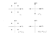
図5は、QPSK信号コンステレーションに式(44)を計算するために必要なシンボルを示す図である。図示されたように、式(44)の最後の項である式(47)は、+C3または−C3である。前記最後の項がマイナスである場合、式(44)を最小化するs1及びs3の検出は、式(44)の1番目の項である FIG. 5 is a diagram illustrating symbols necessary for calculating Equation (44) in the QPSK signal constellation. As shown, equation (47), which is the last term of equation (44), is + C 3 or -C 3 . If the last term is negative, the detection of s 1 and s 3 that minimizes equation (44) is the first term of equation (44).
![]()
![]()
![]()
![]()
これは、式(45)及びs2、s4に対しても同一に適用される。式(48)及び式(49)の最小化は、臨界値R1、R3に最も近接したs1及びs3を決定すること、つまり、臨界値検出を遂行することと同一である。 This applies equally to equation (45) and s 2 and s 4 . The minimization of equations (48) and (49) is the same as determining s 1 and s 3 that are closest to the critical values R 1 , R 3 , that is, performing critical value detection.
前記判別結果が最小値でない場合、メトリック計算器470は、前記チャネル利得及び前記受信信号によって計算されたR1、R3、C3を利用して式(44)を計算して、可能な全てのシンボルサブ組み合わせに対するメトリック値(Metric values)を計算する。メトリック計算器470は、R1、R3、C3を直接計算するか、または、臨界値検出器460から受信することができる。後者の場合、判別器462は、前記判別結果が最小値でない場合、シンボル検出のためにR1、R3、C3をメトリック計算器470に伝達する。最小メトリック検出器480は、メトリック計算器470によって求められたメトリック値を利用して最小のメトリック値を有するようにするs1’、s3’を検出する。
If the determination result is not the minimum value, the
第2デコーダ445も同一の方式によって動作する。第1デコーダ440がs1’及びs3’を検出し、第2デコーダ445がs2’及びs4’を検出した後、並/直列変換器(Parallel to Serial Converter)490は、前記検出されたシンボルを順次に配列し、最終的にシンボル組み合わせs1’、s2’、s3’、s4’を出力する。
The
図6のように構成される受信器において、1つのデコーダは、1回の複素乗算(つまり、4回の実数乗算)、1回の実数乗算、及び3回の最小値判別を遂行する。最小値の判別は、予め貯蔵された最小値の比較演算であるので、結局5回の実数乗算及び3回の比較が必要である。符号がマイナスである確率は、QPSKに対して1/2であるので、2つのシンボル毎に必要な演算量は平均的に122回の実数乗算、64回の実数足し算、及び22回の比較である。表1に示すように、図6に示す受信器は、図4に示す受信器に比べて半分程度の計算複雑度を有する。 In the receiver configured as shown in FIG. 6, one decoder performs one complex multiplication (that is, four real number multiplications), one real number multiplication, and three minimum value determinations. Since the determination of the minimum value is a comparison operation of the minimum value stored in advance, after all, real number multiplication and three comparisons are necessary. Since the probability that the sign is negative is ½ of QPSK, the amount of computation required for each two symbols is 122 real multiplications, 64 real additions, and 22 comparisons on average. is there. As shown in Table 1, the receiver shown in FIG. 6 has about half the computational complexity of the receiver shown in FIG.
図7は、本発明によるブロック符号化技術と従来のブロック符号化技術を信号対雑音比(Signal to Noise Ratio: SNR)に対するビットエラー率(Bit Error Rate: BER)の観点で比較したグラフである。図7を参照すると、参照番号510は、2つのアンテナを使用するAlamoutiによる空間-時間ブロック符号化の効率であり、参照番号520は、列間に直交である8×3符号化行列を使用するTarokhによる空間-時間ブロック符号化の効率であり、参照部号530は、最適化されなかった位相値を有する4×3符号化行列を使用する空間-時間ブロック符号化の効率であり、参照番号540は、本発明によって最適化された位相値を有する4×3符号化行列を使用する空間-時間ブロック符号化の効率である。図示されたように、本発明によって最適化された位相値を有するブロック符号は、同一のSNR環境でより低いBERを有する。
FIG. 7 is a graph comparing a block coding technique according to the present invention and a conventional block coding technique in terms of a bit error rate (BER) with respect to a signal to noise ratio (SNR). . Referring to FIG. 7,
以上、3つの送信アンテナを使用する構造に関して説明したが、図6に示す受信器は、少なくとも3つの送信アンテナを使用して位相回転されたシンボルを送受信する送受信器に適用できることは明白である。例えば、4つの送信アンテナを使用する場合の符号化行列は、式(50)に示すようである。 Although the structure using three transmission antennas has been described above, it is obvious that the receiver shown in FIG. 6 can be applied to a transmitter / receiver that transmits and receives phase-rotated symbols using at least three transmission antennas. For example, the encoding matrix when using four transmission antennas is as shown in Equation (50).
式(50)を使用する場合、図6に示すデコーダ440、445においてメトリック計算器470、475は、式(51)及び式(52)を最小化するシンボルを検出する。
When equation (50) is used,
![]()
![]()
ここで、R1、R3、R13、R2、R4、R24は、数(53)のように定義される。 Here, R 1 , R 3 , R 13 , R 2 , R 4 , R 24 are defined as the number (53).
臨界値検出器460は、R1及びR3に近接するシンボルを予め検出し、臨界値検出器465は、R2及びR4に近接するシンボルを予め検出する。判別器462、467は、
The
及び as well as
![]()
![]()
が最小値を有するか否かを判別する。その値が最小である場合、判別器462、467は、予め検出されたシンボルを最終シンボルとして出力する。メトリック計算器470、475は、式(54)及び式(55)が最小値を有しない時のみに式(51)及び式(52)を最小化するシンボルを検出する。
It is determined whether or not has a minimum value. When the value is minimum, the
前述の如く、本発明を具体的な一実施形態を参照して詳細に説明してきたが、本発明の範囲は前述の一実施形態によって限られるべきではなく、本発明の範囲内で様々な変形が可能であるということは、当該技術分野における通常の知識を持つ者には明らかである。 As described above, the present invention has been described in detail with reference to a specific embodiment. However, the scope of the present invention should not be limited by the above-described embodiment, and various modifications may be made within the scope of the present invention. It is clear to those with ordinary knowledge in the art that this is possible.
220、222 直/並列変換器
230 符号化器
240、242、244 送信アンテナ
310、315 受信アンテナ
320 チャネル推定器
330 シンボル配列器
340 第1デコーダ
345 第2デコーダ
350 シンボル発生器
352 位相回転器
370 メトリック計算器
220, 222 Serial /
Claims (16)
前記受信アンテナを通じて受信された信号からNxMの符号化シンボル行列を構成するシンボル配列器と、
前記受信アンテナを通じて受信された信号によりM個の送信アンテナそれぞれと前記受信アンテナ間のチャンネル利得を推定するチャンネル推定器と、
前記チャンネル利得と前記NxMの符号化シンボル行列を用いてN個の送信シンボルのうち、N/2個のシンボルを検出する第1デコーダと;
前記チャンネル利得と前記NxMの符号化シンボル行列を用いてN個の送信シンボルのうち残りのN/2個のシンボルを検出する第2デコーダと、
前記第1及び第2デコーダにより検出されたN個のシンボルを一つのシンボル列に出力する並/直列変換器とを含み、
前記第1及び第2デコーダは、前記受信信号と前記チャネル利得を利用して、臨界値検出によって2つのシンボルを予め検出し、前記予め検出されたシンボルの積と、前記M個の送信アンテナのチャンネル利得により決定される定数との積が最小である場合、前記予め検出されたシンボルを最終シンボルとして出力し、
ここで、前記Mは3であり、前記Nは4であることを特徴とする無線通信システムの受信装置。 One or more receiving antennas;
A symbol array that constitutes an N × M encoded symbol matrix from the signal received through the receiving antenna;
A channel estimator for estimating a channel gain between each of the M transmitting antennas and the receiving antenna according to a signal received through the receiving antenna;
A first decoder for detecting N / 2 symbols out of N transmission symbols using the channel gain and the N × M encoded symbol matrix;
A second decoder for detecting remaining N / 2 symbols out of N transmission symbols using the channel gain and the N × M encoded symbol matrix;
A parallel / serial converter for outputting N symbols detected by the first and second decoders to one symbol string;
The first and second decoders detect in advance two symbols by detecting a critical value using the received signal and the channel gain, the product of the previously detected symbols, and the M transmission antennas. If the product of the constant determined by the channel gain is minimum, the previously detected symbol is output as the final symbol;
Here, the receiving apparatus of the wireless communication system, wherein M is 3 and N is 4.
ここで、r1、r2、r3、r4は各時間区間で受信されたシンボルであり、h1、h2、h3は各送信アンテナ別に測定されたチャンネル利得であることを特徴とする請求項1記載の無線通信システムの受信装置。 The first decoder comprises:
Here, r 1 , r 2 , r 3 , r 4 are symbols received in each time interval, and h 1 , h 2 , h 3 are channel gains measured for each transmitting antenna. A receiving apparatus for a wireless communication system according to claim 1.
ここで、Re{}は、{}内の複素数から実数成分を求める演算であり、C3は
前記位相回転は、受信側で遂行されるものであり、
前記位相回転の位相値は、前記各シンボルに対応するシンボルのいずれかについて送信側で遂行された位相回転の位相値と同一値であり、
前記送信側で遂行された位相回転は、伝送シンボルの直交性を維持するために入力シンボルのうち一部シンボルを位相回転したものであることを特徴とする請求項2記載の無線通信システムの受信装置。 The first decoder
Here, Re {} is an operation for obtaining a real component from a complex number in {}, and C 3 is
The phase rotation is performed on the receiving side,
The phase value of the phase rotation is the same value as the phase value of the phase rotation performed on the transmitting side for any of the symbols corresponding to each symbol,
The reception of the radio communication system according to claim 2, wherein the phase rotation performed on the transmission side is a phase rotation of a part of input symbols in order to maintain orthogonality of transmission symbols. apparatus.
前記判別値が最小でない場合、
前記メトリック値のうち最小メトリック値を選択し、前記最小メトリック値に対応したサブ組み合わせを構成するN/2個のシンボルを送信シンボルに出力する最小メトリック検出器とをさらに備え、
前記第2デコーダは、
前記判別値が最小でない場合、
前記メトリック値のうち最小メトリック値を選択し、前記最小メトリック値に対応したサブ組み合わせを構成するN/2個のシンボルを送信シンボルに出力する最小メトリック検出器と、をさらに備えることを特徴とする請求項3記載の無線通信システムの受信装置。 The first decoder comprises:
If the discriminant value is not minimum,
A minimum metric detector that selects a minimum metric value from the metric values and outputs N / 2 symbols constituting a sub-combination corresponding to the minimum metric value to a transmission symbol;
The second decoder
If the discriminant value is not minimum,
A minimum metric detector that selects a minimum metric value from the metric values and outputs N / 2 symbols constituting a sub-combination corresponding to the minimum metric value to a transmission symbol; The receiving device of the radio | wireless communications system of Claim 3.
ここで、r1、r2、r3、r4は各時間区間で受信されたシンボルであり、h1、h2、h3、h4は各送信アンテナ別に測定されたチャンネル利得であることを特徴とする請求項4記載の無線通信システムの受信装置。 The critical values (R 1 , R 3 ) in the first decoder and the critical values (R 2 , R 4 ) in the second decoder are:
Here, r 1 , r 2 , r 3 , r 4 are symbols received in each time interval, and h 1 , h 2 , h 3 , h 4 are channel gains measured for each transmission antenna. The receiving apparatus of the radio | wireless communications system of Claim 4 characterized by these.
ここで、x1、x2、x3、x4は位相回転が遂行されたシンボルを含むサブ組み合わせを構成する各シンボルであり、
前記位相回転は、受信側で遂行されるものであり、
前記位相回転の位相値は、前記各シンボルに対応するシンボルのいずれかについて送信側で遂行された位相回転の位相値と同一値であり、
前記送信側で遂行された位相回転は、伝送シンボルの直交性を維持するために入力シンボルのうち一部シンボルを位相回転したものであることを特徴とする請求項5記載の無線通信システムの受信装置。 The first decoder
Here, x 1 , x 2 , x 3 , x 4 are symbols constituting a sub-combination including symbols subjected to phase rotation,
The phase rotation is performed on the receiving side,
The phase value of the phase rotation is the same value as the phase value of the phase rotation performed on the transmitting side for any of the symbols corresponding to each symbol,
6. The radio communication system according to claim 5, wherein the phase rotation performed on the transmission side is a phase rotation of a part of input symbols in order to maintain orthogonality of transmission symbols. apparatus.
前記判別値が最小でない場合、
前記メトリック値のうち最小メトリック値を選択し、前記最小メトリック値に対応したサブ組み合わせを構成するN/2個のシンボルを送信シンボルに出力する最小メトリック検出器と、をさらに備え、
前記第2デコーダは、
前記判別値が最小でない場合、
前記メトリック値のうち最小メトリック値を選択し、前記最小メトリック値に対応したサブ組み合わせを構成するN/2個のシンボルを送信シンボルに出力する最小メトリック検出器と、をさらに備えることを特徴とする請求項6記載の無線通信システムの受信装置。 The first decoder comprises:
If the discriminant value is not minimum,
A minimum metric detector that selects a minimum metric value from the metric values and outputs N / 2 symbols constituting a sub-combination corresponding to the minimum metric value to a transmission symbol; and
The second decoder
If the discriminant value is not minimum,
A minimum metric detector that selects a minimum metric value from the metric values and outputs N / 2 symbols constituting a sub-combination corresponding to the minimum metric value to a transmission symbol; The receiving apparatus of the radio | wireless communications system of Claim 6.
N/2個のシンボルで構成可能なすべてのサブ組み合わせを生成して順次に出力するシンボル発生器と、
前記シンボル発生器から出力されるN/2個のシンボルのうち少なくとも一つのシンボルを予め決定された位相値により位相回転させる位相回転器と、
前記NxMの符号化シンボル行列を構成する符号化シンボルと前記チャンネル利得により一つのサブ組み合わせを構成するN/2個のシンボルそれぞれに対応した臨界値を計算し、前記位相回転が遂行されたシンボルを含むすべてのサブ組み合わせのうち前記臨界値に最も近接したサブ組み合わせを予め検出(pre-detection)する臨界値検出器と、
前記チャンネル利得により計算された整数値と前記予め検出されたサブ組み合わせを構成するN/2個のシンボルにより判別値を推定し、前記判別値が最小である場合、前記予め検出されたサブ組み合わせを構成するN/2個のシンボルを送信シンボルに出力する判別器と、からなり、
前記位相回転は、受信側で遂行されるものであり、
前記位相回転の位相値は、前記各シンボルに対応するシンボルのいずれかについて送信側で遂行された位相回転の位相値と同一値であり、
前記送信側で遂行された位相回転は、伝送シンボルの直交性を維持するために入力シンボルのうち一部シンボルを位相回転したものであることを特徴とする請求項1記載の無線通信システムの受信装置。 Each of the first and second decoders includes:
A symbol generator that generates and sequentially outputs all subcombinations of N / 2 symbols, and
A phase rotator that rotates at least one symbol out of N / 2 symbols output from the symbol generator by a predetermined phase value;
A critical value corresponding to each of N / 2 symbols constituting one sub-combination is calculated based on the coding symbols constituting the NxM coded symbol matrix and the channel gain, and the symbols subjected to the phase rotation are calculated. A critical value detector for pre-detecting a sub-combination closest to the critical value among all the sub-combinations including,
When a discriminant value is estimated from the integer value calculated by the channel gain and N / 2 symbols constituting the pre-detected sub-combination, and the discriminant value is minimum, the pre-detected sub-combination is A discriminator for outputting N / 2 symbols to be transmitted symbols,
The phase rotation is performed on the receiving side,
The phase value of the phase rotation is the same value as the phase value of the phase rotation performed on the transmitting side for any of the symbols corresponding to each symbol,
The reception of the radio communication system according to claim 1, wherein the phase rotation performed on the transmission side is a phase rotation of a part of input symbols in order to maintain orthogonality of transmission symbols. apparatus.
ここで、r1、r2、r3、r4は各時間区間で受信されたシンボルであり、h1、h2、h3は各送信アンテナ別に測定されたチャンネル利得であることを特徴とする請求項8記載の無線通信システムの受信装置。 The critical value detector of the first decoder is:
Here, r 1 , r 2 , r 3 , r 4 are symbols received in each time interval, and h 1 , h 2 , h 3 are channel gains measured for each transmitting antenna. A receiving apparatus for a wireless communication system according to claim 8.
ここで、Re{}は、{}内の複素数から実数成分を求める演算であり、C3は
Here, Re {} is an operation for obtaining a real component from a complex number in {}, and C 3 is
前記第2デコーダのメトリック計算器は、前記判別値が最小でない場合、
The metric calculator of the second decoder, when the discriminant value is not minimum,
ここで、r1、r2、r3、r4は各時間区間で受信されたシンボルであり、h1、h2、h3、h4は各送信アンテナ別に測定されたチャンネル利得であることを特徴とする請求項11記載の無線通信システムの受信装置。 The critical value detector of the first decoder and the critical value detector of the second decoder are:
Here, r 1 , r 2 , r 3 , r 4 are symbols received in each time interval, and h 1 , h 2 , h 3 , h 4 are channel gains measured for each transmission antenna. The receiving apparatus of the radio | wireless communications system of Claim 11 characterized by these.
ここで、x1、x2、x3、x4は位相回転が遂行されたシンボルを含むサブ組み合わせを構成する各シンボルであり、
Here, x 1 , x 2 , x 3 , x 4 are symbols constituting a sub-combination including symbols subjected to phase rotation,
前記第2デコーダのメトリック計算器は、前記判別値が最小でない場合、
The metric calculator of the second decoder, when the discriminant value is not minimum,
M個の送信アンテナから少なくとも一つまたは複数の受信アンテナに受信された信号を4個の時間区間の間に受信する過程と、
前記受信アンテナを通じて受信された信号からNxMの符号化シンボル行列を構成する過程と、
前記M個の送信アンテナから前記一つまたは複数の受信アンテナへのチャンネル利得をそれぞれ示すM個のチャンネル利得を推定する過程と、
前記チャンネル利得と前記シンボル配列器により受信された信号を用いてN個の送信シンボルのうち、N/2個のシンボルを検出する過程と;
前記チャンネル利得と前記シンボル配列器により受信された信号を用いてN個の送信シンボルのうち、残りのN/2個のシンボルを検出する過程と、
前記検出されたN個のシンボルを順序に配列して出力する過程と、を含み、
前記N/2個のシンボルを検出する過程は、
N/2個のシンボルを含む、可能な全てのシンボルのサブ組み合わせに対してメトリック値を求め、前記求められたメトリック値のうち最小のメトリック値を有するN/2個のシンボルを最終シンボルとして出力し、
前記最小のメトリック値を有するN/2個のシンボルは、前記受信信号と前記チャネル利得を利用して、臨界値検出によって2つのシンボルを予め検出し、前記予め検出されたシンボルの積と、前記M個の送信アンテナのチャンネル利得により決定される定数との積が最小であるN/2個のシンボルであり、
ここで、前記Mは3であり、前記Nは4であることを特徴とする無線通信システムの受信方法。 A method for receiving complex symbols in a wireless communication system, comprising:
Receiving signals received from M transmit antennas to at least one or more receive antennas during four time intervals;
Constructing an NxM encoded symbol matrix from signals received through the receive antenna;
Estimating M channel gains respectively indicating channel gains from the M transmit antennas to the one or more receive antennas;
Detecting N / 2 symbols out of N transmission symbols using the channel gain and the signal received by the symbol arrayer;
Detecting the remaining N / 2 symbols out of N transmission symbols using the channel gain and the signal received by the symbol arrayer;
Arranging the detected N symbols in order and outputting them,
The process of detecting the N / 2 symbols includes:
Metric values are obtained for all possible symbol sub-combinations including N / 2 symbols, and N / 2 symbols having the smallest metric value among the obtained metric values are output as final symbols. And
N / 2 symbols having the minimum metric value are detected in advance by critical value detection using the received signal and the channel gain, and the product of the previously detected symbols, N / 2 symbols with the smallest product with a constant determined by the channel gain of M transmit antennas,
Here, the reception method of the wireless communication system, wherein M is 3 and N is 4.
それぞれN/2個のシンボルを含む、可能な全てのシンボルのサブ組み合わせを発生する段階と、
前記N/2個のシンボルのうち一つのシンボルを予め決定された位相値だけ回転させる段階と、
前記受信された信号と前記チャンネル利得を用いて前記位相回転されたシンボルを含むシンボルサブ組み合わせに対するメトリック値を求める段階と、
前記求められたメトリック値を用いて最小のメトリック値を有するN/2個のシンボルを検出する段階と、を含むことを特徴とする請求項15記載の受信方法。 The process of detecting each of the N / 2 symbols is as follows:
Generating all possible symbol sub-combinations, each containing N / 2 symbols;
Rotating one of the N / 2 symbols by a predetermined phase value;
Determining a metric value for a symbol sub-combination that includes the phase rotated symbol using the received signal and the channel gain;
16. The reception method according to claim 15, further comprising: detecting N / 2 symbols having a minimum metric value using the obtained metric value.
Applications Claiming Priority (1)
| Application Number | Priority Date | Filing Date | Title |
|---|---|---|---|
| KR1020030001456A KR100557085B1 (en) | 2003-01-09 | 2003-01-09 | Receiving apparatus for wireless telecommunication system using at least 3 transmit antennas |
Publications (2)
| Publication Number | Publication Date |
|---|---|
| JP2004222282A JP2004222282A (en) | 2004-08-05 |
| JP4157043B2 true JP4157043B2 (en) | 2008-09-24 |
Family
ID=32501495
Family Applications (1)
| Application Number | Title | Priority Date | Filing Date |
|---|---|---|---|
| JP2004004579A Expired - Fee Related JP4157043B2 (en) | 2003-01-09 | 2004-01-09 | Receiving apparatus for wireless communication system using at least three transmitting antennas |
Country Status (5)
| Country | Link |
|---|---|
| US (1) | US7298804B2 (en) |
| EP (1) | EP1437853A2 (en) |
| JP (1) | JP4157043B2 (en) |
| KR (1) | KR100557085B1 (en) |
| CN (1) | CN100356709C (en) |
Families Citing this family (13)
| Publication number | Priority date | Publication date | Assignee | Title |
|---|---|---|---|---|
| EP1356624A2 (en) * | 2000-11-06 | 2003-10-29 | Broadcom Corporation | Super-orthogonal space-time trellis codes, and applications thereof |
| KR100630108B1 (en) * | 2002-10-10 | 2006-09-27 | 삼성전자주식회사 | Transmitting and receiving apparatus for supporting transmission antenna diversity using space-time block code |
| KR100640349B1 (en) * | 2003-01-02 | 2006-10-30 | 삼성전자주식회사 | Transmitting and receiving apparatus for wireless telecommunication system having 3 transmit antennas |
| KR100605860B1 (en) * | 2003-01-09 | 2006-07-31 | 삼성전자주식회사 | Apparatus and method for transmitting in wireless telecommunication system using 4 transmit antennas |
| EP1678867A1 (en) * | 2003-10-23 | 2006-07-12 | Philips Intellectual Property & Standards GmbH | Decoding and reconstruction of data |
| JP4460412B2 (en) * | 2003-11-26 | 2010-05-12 | パナソニック株式会社 | Reception device and partial bit determination method |
| US20050281361A1 (en) * | 2004-06-16 | 2005-12-22 | Broadcom Corporation | Interference cancellation of STBC with multiple streams in OFDM for wlan |
| US7880683B2 (en) | 2004-08-18 | 2011-02-01 | Ruckus Wireless, Inc. | Antennas with polarization diversity |
| US8031129B2 (en) | 2004-08-18 | 2011-10-04 | Ruckus Wireless, Inc. | Dual band dual polarization antenna array |
| US7646343B2 (en) | 2005-06-24 | 2010-01-12 | Ruckus Wireless, Inc. | Multiple-input multiple-output wireless antennas |
| JP4478119B2 (en) | 2005-05-25 | 2010-06-09 | パナソニック株式会社 | Receiver |
| US8644407B2 (en) * | 2008-06-23 | 2014-02-04 | Blackberry Limited | Apparatus, and associated method of phase-offset modulation, for space-time coded wireless communication systems |
| KR101289467B1 (en) * | 2008-12-05 | 2013-07-24 | 삼성전자주식회사 | Apparatus and Method for signal detection using log likelihood ratio |
Family Cites Families (10)
| Publication number | Priority date | Publication date | Assignee | Title |
|---|---|---|---|---|
| BR9908389A (en) * | 1998-03-03 | 2000-10-31 | At & T Corp | Decoding space-time coded signals for wireless communication |
| AU6257399A (en) * | 1998-09-18 | 2000-04-10 | Hesham El Gamal | Method and constructions for space-time codes for psk constellations for spatialdiversity in multiple-element antenna systems |
| US6317411B1 (en) * | 1999-02-22 | 2001-11-13 | Motorola, Inc. | Method and system for transmitting and receiving signals transmitted from an antenna array with transmit diversity techniques |
| KR100526499B1 (en) * | 2000-08-22 | 2005-11-08 | 삼성전자주식회사 | Apparatus for transmit diversity for more than two antennas and method thereof |
| KR100614410B1 (en) * | 2000-12-01 | 2006-08-18 | 주식회사 케이티 | The Apparatus and Method for Detecting the Signals of Space-Time Coding based Transmit Diversity |
| WO2002080375A2 (en) * | 2001-03-28 | 2002-10-10 | Nokia Corporation | Non-zero complex weighted space-time code for multiple antenna transmission |
| US7190734B2 (en) * | 2001-05-25 | 2007-03-13 | Regents Of The University Of Minnesota | Space-time coded transmissions within a wireless communication network |
| KR100763378B1 (en) * | 2001-07-27 | 2007-10-05 | 엘지전자 주식회사 | Method for transmitting/receiving using plurality of antennas, system for the same |
| WO2003023996A1 (en) * | 2001-09-12 | 2003-03-20 | Infineon Technologies Ag | Cdma wireless systems |
| US8218609B2 (en) * | 2002-10-25 | 2012-07-10 | Qualcomm Incorporated | Closed-loop rate control for a multi-channel communication system |
-
2003
- 2003-01-09 KR KR1020030001456A patent/KR100557085B1/en not_active IP Right Cessation
- 2003-10-24 US US10/692,896 patent/US7298804B2/en not_active Expired - Fee Related
- 2003-12-24 EP EP20030079192 patent/EP1437853A2/en not_active Withdrawn
-
2004
- 2004-01-07 CN CNB200410001378XA patent/CN100356709C/en not_active Expired - Fee Related
- 2004-01-09 JP JP2004004579A patent/JP4157043B2/en not_active Expired - Fee Related
Also Published As
| Publication number | Publication date |
|---|---|
| KR20040064156A (en) | 2004-07-16 |
| CN1518241A (en) | 2004-08-04 |
| US20040137864A1 (en) | 2004-07-15 |
| US7298804B2 (en) | 2007-11-20 |
| KR100557085B1 (en) | 2006-03-03 |
| EP1437853A2 (en) | 2004-07-14 |
| JP2004222282A (en) | 2004-08-05 |
| CN100356709C (en) | 2007-12-19 |
Similar Documents
| Publication | Publication Date | Title |
|---|---|---|
| JP4188814B2 (en) | Transmitting apparatus and receiving apparatus for wireless communication system having three transmitting antennas | |
| KR100892104B1 (en) | Apparatus and method for generating llr in mimo communication system | |
| KR100630108B1 (en) | Transmitting and receiving apparatus for supporting transmission antenna diversity using space-time block code | |
| KR100667821B1 (en) | A method of soft bit metric calculation with direct matrix inversion MIMO detection | |
| JP4208874B2 (en) | Decoder for multiplexed transmission system | |
| US8229016B2 (en) | MIMO receiver and MIMO communication system | |
| KR100690873B1 (en) | Decoding apparatus and method of mimo system | |
| JP2007166668A (en) | Transmitting and receiving apparatus for supporting transmit antenna diversity using space-time block code | |
| JP4157043B2 (en) | Receiving apparatus for wireless communication system using at least three transmitting antennas | |
| KR101106682B1 (en) | Apparatus and method for generating of multiple antenna log likelihood ratio | |
| KR20090046599A (en) | Apparatus and method for detecting signal in multi-antenna system | |
| JP4064354B2 (en) | Transmitting and receiving apparatus for wireless communication system using four transmitting antennas | |
| EP2113147A2 (en) | Scaled and rotated alamouti coding | |
| JP4377435B2 (en) | Apparatus and method for space-time block coding with maximum diversity and maximum transmission rate using two transmission antennas | |
| KR100678272B1 (en) | Apparatus and method for receiving differential space-time block code | |
| KR101266864B1 (en) | Method and transmitting device for encoding data in a differential spacetime block code | |
| KR101789819B1 (en) | Signal detection device and method for multiple input multiple output system using channel coding | |
| KR20100007446A (en) | Apparatus and method for generating log likelihood ration in multiple antenna communication system |
Legal Events
| Date | Code | Title | Description |
|---|---|---|---|
| A977 | Report on retrieval |
Free format text: JAPANESE INTERMEDIATE CODE: A971007 Effective date: 20050610 |
|
| A131 | Notification of reasons for refusal |
Free format text: JAPANESE INTERMEDIATE CODE: A131 Effective date: 20051018 |
|
| A601 | Written request for extension of time |
Free format text: JAPANESE INTERMEDIATE CODE: A601 Effective date: 20060118 |
|
| A602 | Written permission of extension of time |
Free format text: JAPANESE INTERMEDIATE CODE: A602 Effective date: 20060123 |
|
| A521 | Written amendment |
Free format text: JAPANESE INTERMEDIATE CODE: A523 Effective date: 20060417 |
|
| A131 | Notification of reasons for refusal |
Free format text: JAPANESE INTERMEDIATE CODE: A131 Effective date: 20061031 |
|
| A601 | Written request for extension of time |
Free format text: JAPANESE INTERMEDIATE CODE: A601 Effective date: 20070131 |
|
| A602 | Written permission of extension of time |
Free format text: JAPANESE INTERMEDIATE CODE: A602 Effective date: 20070206 |
|
| A521 | Written amendment |
Free format text: JAPANESE INTERMEDIATE CODE: A523 Effective date: 20070501 |
|
| A131 | Notification of reasons for refusal |
Free format text: JAPANESE INTERMEDIATE CODE: A131 Effective date: 20071116 |
|
| A521 | Written amendment |
Free format text: JAPANESE INTERMEDIATE CODE: A523 Effective date: 20080218 |
|
| A131 | Notification of reasons for refusal |
Free format text: JAPANESE INTERMEDIATE CODE: A131 Effective date: 20080507 |
|
| A521 | Written amendment |
Free format text: JAPANESE INTERMEDIATE CODE: A523 Effective date: 20080515 |
|
| TRDD | Decision of grant or rejection written | ||
| A01 | Written decision to grant a patent or to grant a registration (utility model) |
Free format text: JAPANESE INTERMEDIATE CODE: A01 Effective date: 20080610 |
|
| A01 | Written decision to grant a patent or to grant a registration (utility model) |
Free format text: JAPANESE INTERMEDIATE CODE: A01 |
|
| A61 | First payment of annual fees (during grant procedure) |
Free format text: JAPANESE INTERMEDIATE CODE: A61 Effective date: 20080710 |
|
| FPAY | Renewal fee payment (event date is renewal date of database) |
Free format text: PAYMENT UNTIL: 20110718 Year of fee payment: 3 |
|
| R150 | Certificate of patent or registration of utility model |
Free format text: JAPANESE INTERMEDIATE CODE: R150 Ref document number: 4157043 Country of ref document: JP Free format text: JAPANESE INTERMEDIATE CODE: R150 |
|
| FPAY | Renewal fee payment (event date is renewal date of database) |
Free format text: PAYMENT UNTIL: 20120718 Year of fee payment: 4 |
|
| R250 | Receipt of annual fees |
Free format text: JAPANESE INTERMEDIATE CODE: R250 |
|
| FPAY | Renewal fee payment (event date is renewal date of database) |
Free format text: PAYMENT UNTIL: 20120718 Year of fee payment: 4 |
|
| FPAY | Renewal fee payment (event date is renewal date of database) |
Free format text: PAYMENT UNTIL: 20130718 Year of fee payment: 5 |
|
| R250 | Receipt of annual fees |
Free format text: JAPANESE INTERMEDIATE CODE: R250 |
|
| R250 | Receipt of annual fees |
Free format text: JAPANESE INTERMEDIATE CODE: R250 |
|
| R250 | Receipt of annual fees |
Free format text: JAPANESE INTERMEDIATE CODE: R250 |
|
| R250 | Receipt of annual fees |
Free format text: JAPANESE INTERMEDIATE CODE: R250 |
|
| R250 | Receipt of annual fees |
Free format text: JAPANESE INTERMEDIATE CODE: R250 |
|
| R250 | Receipt of annual fees |
Free format text: JAPANESE INTERMEDIATE CODE: R250 |
|
| R250 | Receipt of annual fees |
Free format text: JAPANESE INTERMEDIATE CODE: R250 |
|
| LAPS | Cancellation because of no payment of annual fees |