JP4155343B2 - An optical system for guiding light from two scenes to the viewer's eye alternatively or simultaneously - Google Patents
An optical system for guiding light from two scenes to the viewer's eye alternatively or simultaneously Download PDFInfo
- Publication number
- JP4155343B2 JP4155343B2 JP52266698A JP52266698A JP4155343B2 JP 4155343 B2 JP4155343 B2 JP 4155343B2 JP 52266698 A JP52266698 A JP 52266698A JP 52266698 A JP52266698 A JP 52266698A JP 4155343 B2 JP4155343 B2 JP 4155343B2
- Authority
- JP
- Japan
- Prior art keywords
- scene
- observer
- light
- eye
- optical system
- Prior art date
- Legal status (The legal status is an assumption and is not a legal conclusion. Google has not performed a legal analysis and makes no representation as to the accuracy of the status listed.)
- Expired - Fee Related
Links
- 230000003287 optical effect Effects 0.000 title claims description 346
- 210000001508 eye Anatomy 0.000 claims description 219
- 210000003128 head Anatomy 0.000 claims description 56
- 230000000007 visual effect Effects 0.000 claims description 34
- 239000000463 material Substances 0.000 claims description 26
- 230000005856 abnormality Effects 0.000 claims description 17
- 230000007246 mechanism Effects 0.000 description 28
- 239000011521 glass Substances 0.000 description 26
- 238000000034 method Methods 0.000 description 21
- 230000000903 blocking effect Effects 0.000 description 20
- 230000004438 eyesight Effects 0.000 description 16
- 238000012937 correction Methods 0.000 description 10
- 230000004379 myopia Effects 0.000 description 7
- 208000001491 myopia Diseases 0.000 description 7
- 206010020675 Hypermetropia Diseases 0.000 description 6
- 230000004305 hyperopia Effects 0.000 description 6
- 201000006318 hyperopia Diseases 0.000 description 6
- 201000010041 presbyopia Diseases 0.000 description 6
- 210000001525 retina Anatomy 0.000 description 6
- 230000008901 benefit Effects 0.000 description 5
- 230000008859 change Effects 0.000 description 5
- 210000005252 bulbus oculi Anatomy 0.000 description 4
- 238000000427 thin-film deposition Methods 0.000 description 4
- 230000000694 effects Effects 0.000 description 3
- 238000004519 manufacturing process Methods 0.000 description 3
- 238000013459 approach Methods 0.000 description 2
- 230000007812 deficiency Effects 0.000 description 2
- 230000007935 neutral effect Effects 0.000 description 2
- 125000002066 L-histidyl group Chemical group [H]N1C([H])=NC(C([H])([H])[C@](C(=O)[*])([H])N([H])[H])=C1[H] 0.000 description 1
- 230000002411 adverse Effects 0.000 description 1
- 238000005452 bending Methods 0.000 description 1
- 210000004556 brain Anatomy 0.000 description 1
- 238000010276 construction Methods 0.000 description 1
- 210000004087 cornea Anatomy 0.000 description 1
- 230000008878 coupling Effects 0.000 description 1
- 238000010168 coupling process Methods 0.000 description 1
- 238000005859 coupling reaction Methods 0.000 description 1
- 230000003247 decreasing effect Effects 0.000 description 1
- 238000005516 engineering process Methods 0.000 description 1
- 210000000887 face Anatomy 0.000 description 1
- 239000010408 film Substances 0.000 description 1
- 239000012535 impurity Substances 0.000 description 1
- 238000012986 modification Methods 0.000 description 1
- 230000004048 modification Effects 0.000 description 1
- 238000005498 polishing Methods 0.000 description 1
- 238000012549 training Methods 0.000 description 1
- 230000004304 visual acuity Effects 0.000 description 1
Images


Classifications
-
- G—PHYSICS
- G02—OPTICS
- G02B—OPTICAL ELEMENTS, SYSTEMS OR APPARATUS
- G02B3/00—Simple or compound lenses
- G02B3/10—Bifocal lenses; Multifocal lenses
-
- G—PHYSICS
- G02—OPTICS
- G02B—OPTICAL ELEMENTS, SYSTEMS OR APPARATUS
- G02B27/00—Optical systems or apparatus not provided for by any of the groups G02B1/00 - G02B26/00, G02B30/00
- G02B27/01—Head-up displays
- G02B27/0101—Head-up displays characterised by optical features
- G02B27/0103—Head-up displays characterised by optical features comprising holographic elements
-
- G—PHYSICS
- G02—OPTICS
- G02B—OPTICAL ELEMENTS, SYSTEMS OR APPARATUS
- G02B27/00—Optical systems or apparatus not provided for by any of the groups G02B1/00 - G02B26/00, G02B30/00
- G02B27/01—Head-up displays
- G02B27/017—Head mounted
- G02B27/0172—Head mounted characterised by optical features
-
- G—PHYSICS
- G02—OPTICS
- G02B—OPTICAL ELEMENTS, SYSTEMS OR APPARATUS
- G02B27/00—Optical systems or apparatus not provided for by any of the groups G02B1/00 - G02B26/00, G02B30/00
- G02B27/02—Viewing or reading apparatus
-
- G—PHYSICS
- G02—OPTICS
- G02B—OPTICAL ELEMENTS, SYSTEMS OR APPARATUS
- G02B27/00—Optical systems or apparatus not provided for by any of the groups G02B1/00 - G02B26/00, G02B30/00
- G02B27/10—Beam splitting or combining systems
- G02B27/1066—Beam splitting or combining systems for enhancing image performance, like resolution, pixel numbers, dual magnifications or dynamic range, by tiling, slicing or overlapping fields of view
-
- G—PHYSICS
- G02—OPTICS
- G02B—OPTICAL ELEMENTS, SYSTEMS OR APPARATUS
- G02B27/00—Optical systems or apparatus not provided for by any of the groups G02B1/00 - G02B26/00, G02B30/00
- G02B27/10—Beam splitting or combining systems
- G02B27/1086—Beam splitting or combining systems operating by diffraction only
-
- G—PHYSICS
- G02—OPTICS
- G02B—OPTICAL ELEMENTS, SYSTEMS OR APPARATUS
- G02B27/00—Optical systems or apparatus not provided for by any of the groups G02B1/00 - G02B26/00, G02B30/00
- G02B27/10—Beam splitting or combining systems
- G02B27/12—Beam splitting or combining systems operating by refraction only
- G02B27/123—The splitting element being a lens or a system of lenses, including arrays and surfaces with refractive power
-
- G—PHYSICS
- G02—OPTICS
- G02B—OPTICAL ELEMENTS, SYSTEMS OR APPARATUS
- G02B27/00—Optical systems or apparatus not provided for by any of the groups G02B1/00 - G02B26/00, G02B30/00
- G02B27/10—Beam splitting or combining systems
- G02B27/14—Beam splitting or combining systems operating by reflection only
- G02B27/144—Beam splitting or combining systems operating by reflection only using partially transparent surfaces without spectral selectivity
-
- G—PHYSICS
- G02—OPTICS
- G02C—SPECTACLES; SUNGLASSES OR GOGGLES INSOFAR AS THEY HAVE THE SAME FEATURES AS SPECTACLES; CONTACT LENSES
- G02C7/00—Optical parts
- G02C7/02—Lenses; Lens systems ; Methods of designing lenses
-
- G—PHYSICS
- G02—OPTICS
- G02C—SPECTACLES; SUNGLASSES OR GOGGLES INSOFAR AS THEY HAVE THE SAME FEATURES AS SPECTACLES; CONTACT LENSES
- G02C7/00—Optical parts
- G02C7/02—Lenses; Lens systems ; Methods of designing lenses
- G02C7/08—Auxiliary lenses; Arrangements for varying focal length
- G02C7/088—Lens systems mounted to spectacles
-
- G—PHYSICS
- G02—OPTICS
- G02B—OPTICAL ELEMENTS, SYSTEMS OR APPARATUS
- G02B27/00—Optical systems or apparatus not provided for by any of the groups G02B1/00 - G02B26/00, G02B30/00
- G02B27/01—Head-up displays
- G02B27/0101—Head-up displays characterised by optical features
- G02B2027/0132—Head-up displays characterised by optical features comprising binocular systems
-
- G—PHYSICS
- G02—OPTICS
- G02B—OPTICAL ELEMENTS, SYSTEMS OR APPARATUS
- G02B27/00—Optical systems or apparatus not provided for by any of the groups G02B1/00 - G02B26/00, G02B30/00
- G02B27/01—Head-up displays
- G02B27/0149—Head-up displays characterised by mechanical features
- G02B2027/0154—Head-up displays characterised by mechanical features with movable elements
-
- G—PHYSICS
- G02—OPTICS
- G02B—OPTICAL ELEMENTS, SYSTEMS OR APPARATUS
- G02B27/00—Optical systems or apparatus not provided for by any of the groups G02B1/00 - G02B26/00, G02B30/00
- G02B27/01—Head-up displays
- G02B27/017—Head mounted
- G02B2027/0178—Eyeglass type
-
- G—PHYSICS
- G02—OPTICS
- G02C—SPECTACLES; SUNGLASSES OR GOGGLES INSOFAR AS THEY HAVE THE SAME FEATURES AS SPECTACLES; CONTACT LENSES
- G02C2202/00—Generic optical aspects applicable to one or more of the subgroups of G02C7/00
- G02C2202/20—Diffractive and Fresnel lenses or lens portions
Landscapes
- Physics & Mathematics (AREA)
- General Physics & Mathematics (AREA)
- Optics & Photonics (AREA)
- Health & Medical Sciences (AREA)
- Ophthalmology & Optometry (AREA)
- General Health & Medical Sciences (AREA)
- Spectroscopy & Molecular Physics (AREA)
- Diffracting Gratings Or Hologram Optical Elements (AREA)
- Eyeglasses (AREA)
- Lenses (AREA)
- Optical Communication System (AREA)
Description
発明の分野及び背景
本発明は、二つの光景からの光を、観察者の眼へ、代替的に、あるいは同時に導くための光学系に関し、特に、二つの光景からの光を、観察者の眼へ、代替的に、あるいは同時に導くために、平面光学的アプローチを用いる光学系に関する。したがって、本発明による光学系は、従来の二焦点眼鏡を用いる場合に必要な、観察対象である光景に対して頭と眼とを位置決めしなければならないという面倒な操作を必要としない独創的な二焦点眼鏡を提供することが可能である。さらに、本発明は、幾何学的な、あるいは平面光学的なアプローチを用いる、二つの光景からの光を同時に観察者の一方の眼あるいは両方の眼へ導く光学系に関する。したがって、本発明による光学系は、表示のために能動光を用いるものではない。
この明細書及び特許請求の範囲に用いる用語「光景」は、受動光を介して、すなわち本発明の光学系の外部からの光を介して観察者によって認知される物体あるいは物体のセットを示す。
受動光は、例えば、物体あるいは物体のセットによって反射された、あるいは散乱された光であっても、また、物体あるいは物体のセットからの放射光であってもよい。換言すれば、受動光は、本発明の光学系が存在しない場合でも観察者が認知可能な、本発明の光学系の外部からの光である。
対照的に、ここに用いる用語「能動光」は、対象となる光学系の構成要素から発生する光を含むことを意図する。したがって、例えば、従来のヘッドアップ・ディスプレイ(HUD)システムは、ブラウン管(CRT)を含むため、CRTによって生成される光は能動光である。ここで定義する能動光によるビューは、ここにディスプレイと定義する。ここで言及する用語「光景」は、特に、例えば、HUDシステムで用いるような、能動光によって形成されるディスプレイを除外するものであり、本文で用いる用語「イメージ」は、光景及びディスプレイの両方を意味する。また、実像は光景を、そして虚像はディスプレイを示す。
本発明の光学系は光源を含まないため、本発明の光学系を用いて観察者が認知するすべての光は受動光である。注意すべきこととして、ここに定義するように、本発明の範囲においては、例えば、テレビのスクリーンあるいはコンピュータのモニターからの放射光でさえ、テレビのスクリーンあるいはコンピュータのモニターのどちらもが本発明の光学系の一部ではないため、受動光であると見なされる。
種々の視覚異常のために眼鏡を必要とする人々が、人口の高い割合を占めている。
従来の眼鏡は、典型的に、眼の前の適当な位置に眼鏡を支持するフレームと、各々の眼に対して一つずつフレーム内に収められた二つのレンズとから構成され、各レンズは、眼の特定な視覚異常を補正する焦点特性を持つ。
したがって、例えば、近視の場合、これは、眼のレンズと角膜に力が入り過ぎることから生じる、そして/あるいは眼球が長過ぎることから起こる焦点に関する視覚異常であるが、正の集束能が強すぎるために、遠くの物のイメージが網膜の前に集束し、はっきりと焦点を合わせることができない状態にある。このため、発散レンズを選択して近視眼が焦点を合わすことができる最も遠い点にイメージが形成されるようにする。
他方、遠視の場合、これは、近視の反対で、眼の屈折要素の能力が少な過ぎる、そして/あるいは眼球が短過ぎることから生じるが、遠い物のイメージは、(眼がリラックスしているとき)網膜の背後に形成される。したがって、遠視は収束レンズによって補正する。
近視及び遠視は、遠い物を見る場合の視覚異常である。他方、老視は、近くの物を見ることに関わる視覚異常の一つであり、多くの場合、読む能力を損なうものである。老視は、通常、年齢の経過とともにレンズをなす物質が硬化することから生じ、近くの物に対して眼の焦点を合わせる(適応する)能力が衰えてしまうものである。したがって、老視は、快適に読むことができるように収束レンズによって補正する。
しかしながら、多くの場合、単一眼に、その風景の視覚能力を制限する近視あるいは超近視等の遠距離視覚異常と、読む能力を制限する老視等の短距離視覚異常とが生じる。
このように眼に二重の異常がある者は、遠距離視覚異常に対する補正光学素子を提供する第一のセットと、短距離視覚異常に対する補正光学素子を提供する第二のセットとからなる二つのセットの眼鏡、あるいは択一的に、二焦点眼鏡として本技術において知られる、各々が任意の(異なる)焦点距離と光学特性とを持ち、互いに隣接して配置された二つのレンズの組合せからなる二焦点レンズを含むセットが必要である。多焦点の眼鏡が既知であるが、高価であり、また、多くの人たちがうまく適応できないため、余り使用されていない。
しかしながら、これらの解決方法には不都合がある。読書のために一つ、遠くを見るために一つ、二つの対の眼鏡を用いた場合、近くから遠くの物へ、あるいは遠くから近くの物へと視界を移すときにはいつも眼鏡を変える必要がある。二焦点眼鏡あるいは多焦点眼鏡を用いた場合、近い物を、そして遠くの物を見るために、異なる視線が強いられ、どちらの場合も視野が限定される。通常、読書に対しては、頭をほぼ真っ直ぐ前方へ向けながら眼だけを下げる必要がある。もし、この人に対して、まっすぐ前方に、近い位置に物体を配置した場合、この近い物体をはっきりと見るためには、この人は、頭を後へ傾けながら眼を下げるようにしなければならない。多くの場合、頭と首に問題が生じるため、多くの人は二焦点眼鏡を用いない。
したがって、二つの光景からの光を代替的に、あるいは同時に観察者の眼へ導くための光学系の必要が広く認められ、そのようなものを得ることは非常に有利である。そのような光学系は、見る光景に対して頭と眼とを位置決めする必要がない二重焦点あるいは多焦点眼鏡を提供することが可能である。
相対的に様々な位置にある光景を見たいという状況は日常的に限りなく存在する。例えば、限定せずに、(i)黒板、講師あるいはディスプレイ(例えば、スライド・スクリーン)を見ながらノートをとる。この場合、観察者は、通常、テーブルあるいは筆記板上にある彼のノートと、黒板、講師あるいはディスプレイとの両方を見ることに興味がある。(ii)描画対象物(例えば、風景)を見ながら絵を描く。この場合、観察者は、彼の画板と描画対象物との両方を見ることに興味がある。(iii)スクリーンを見ながらキーボードでタイプする。この場合、インプロのタイピストは、キーボードとスクリーンとの両方を見ることに興味がある。(iv)印刷物(例えば、地図、案内書、本など)を見ながら、あるいは読みながら、もう一つの光景(例えば、道路、器具など)を見る。この場合、観察者は、印刷物と他の光景との両方を見ることに興味がある。
しかし、上記の状況、そして同様な状況においては、観察者が焦点を合わせることができる視野は比較的に狭いため、一時点においては、観察者は一方の光景だけを見ている。このことから不利な点が生じる。(i)観察者は、一方の光景を見ているとき、他の光景における変化に気付くことができない。したがって、例えば、運転手あるいはパイロットは、道路地図あるいは航行マップを見ているとき、同時に前方の道路あるいは空を見ることができない。そして(ii)観察者は、光景間で比較を行うことが難しいと分かる。したがって、画家にとっては、彼の絵と、描画対象物とを比較することが難しく、タイピストにとっては、タイプミスを検出することが難しく、学生にとっては、黒板あるいはディスプレイから彼のノートなどへ正確に内容をコピーすることが難しい。
したがって、二つの光景からの光を同時に観察者の眼へ導く光学系に対する必要性が広く認識され、そのようなものを得ることは大変有利である。
発明の要約
本発明によれば、少なくとも二つの光景からの光を代替的に、あるいは同時に観察者の眼へ導くための光学系が提供される。さらに、二つの光景からの光を同時に観察者の一方の眼あるいは両方の眼へ導くための光学系が提供される。これは、観察者が第一の光景及び第二の光景を同時に見ることを可能にするために用いることができる。本発明による光学系は、単に光景からの受動光を用いるだけで、ヘッドアップ・ディスプレイ(HUD)システムとは対照的に、能動光を用いることはない。
さらに、下記に説明する好適実施例における特徴によれば、本発明による光学系は次のものから構成される。(a)第一の焦点距離を持つ第一のレンズ。(b)第二の焦点距離を持つ第二のレンズ。第一及び第二のレンズは、観察者の一つの眼の前に互いに隣接して配置されるため、いずれの光景からの単一光線も第一及び第二のレンズの一つを介してのみ通過する。そして(c)第一の光景からの第一のレンズを通過した入射光を観察者の眼の中へ導き、そして同時に第二の光景からの第二のレンズを通過した入射光を観察者の眼の中へ導くための光学装置。なお、この光学装置は第一及び第二のレンズと観察者の眼との間に配置される。
本発明のもう一つの実施例によれば、光学系は次のものから構成される。(a)近くの光景を拡大すると共に通過する光の照準を正すための、短い焦点距離を持つ拡大照準接眼レンズ。(b)近くの光景からの拡大照準レンズを通過した入射光を観察者の眼の中へ導き、そして同時に遠くの光景からの入射光を観察者の眼の中へ導くための光学装置。そして(c)遠距離視覚異常を補正するための補正接眼レンズ。この補正レンズは光学装置と観察者の眼との間に配置される。
さらに、好適実施例における特徴によれば、光学装置はホログラフィックプレートを含む。
さらに、好適実施例における特徴によれば、ホログラフィックプレートは少なくとも一つのホログラフィック光学素子を含む。
さらに、好適実施例における特徴によれば、ホログラフィックプレートは、第一のレンズを通過した入射光をホログラフィックプレート内に入れるための第一の入力ホログラフィック光学素子を含む。
さらに、好適実施例における特徴によれば、ホログラフィックプレートは、拡大照準レンズを通過した入射光をホログラフィックプレート内に入れるための第一の入力ホログラフィック光学素子を含む。
さらに、好適実施例における特徴によれば、ホログラフィックプレートは、さらに、第二のレンズを通過した入射光をホログラフィックプレート内に入れるための第二の入力ホログラフィック光学素子を含む。
さらに、好適実施例における特徴によれば、ホログラフィックプレートは、さらに、遠くの光景からの入射光をホログラフィックプレート内に入れるための第二の入力ホログラフィック光学素子を含む。
さらに、好適実施例における特徴によれば、ホログラフィックプレートは、さらに、ホログラフィックプレートに入った光をホログラフィックプレートから出して観察者の眼に到達させるための出力ホログラフィック光学素子を含む。
さらに、好適実施例における特徴によれば、光学装置は少なくとも一つの反射光学素子を含む。
さらに、好適実施例における特徴によれば、光学系は、さらに、(d)少なくとも任意の時間、第一及び第二の光景の一つからの光を観察者の眼に到達させないように遮るための遮光メカニズムからなる。
さらに、好適実施例における特徴によれば、光学系は、さらに(d)少なくとも任意の時間、近くの光景及び遠くの光景の一つからの光を観察者の眼に到達させないように遮るための遮光メカニズムからなる。
本発明のもう一つの実施例によれば、上記のいずれかの実施例による二つの光学系からなる眼鏡が提供される。
本発明のもう一つの実施例によれば、遮光メカニズムを含む二つの光学系からなる三次元視覚認識のためのヘッド・セットが提供される。
本発明のもう一つの実施例によれば、観察者が、第一のイメージ及び第二のイメージによって提示される光景の三次元視覚認識を得るために用いることができる光学系が提供される。この場合、第一及び第二のイメージの各々は、光景の視差情報を含む。この光学系は、第一のホログラフィックプレート及び第二のホログラフィックプレートからなり、第一及び第二のホログラフィックプレートの各々は次のものを含む(a)第一側及び第二側を持つ、光透過材から形成された本体。(b)本体の第一側に形成された少なくとも一つの入力ホログラフィック光学素子。なお、材料、そして入力ホログラフィック光学素子の各々は、本体を入る任意の方向を持つ入射光が回折されてほぼ完全な内反射を起こすように選択する。そして(c)本体の第二側に形成された少なくとも一つの出力ホログラフィック光学素子。このため、どの出力ホログラフィック光学素子に到達する光も、入射光の任意の方向と同様な方向で本体から出る。この場合、第一のホログラフィックプレートは、ほぼ第一のイメージからの光だけを観察者の一方の眼に到達させるためのものであり、第二のホログラフィックプレートは、ほぼ第二のイメージからの光だけを観察者の他方の眼に到達させるためのものである。
さらに、好適実施例における特徴によれば、ホログラフィック光学素子の各々は、さらに、光を遮る遮光メカニズムを含む。
さらに、下記に説明する本発明の好適実施例における特徴によれば、観察者が第一の光景及び第二の光景を見ることを可能にするための方法が提供される。この方法は次のステップからなる。(a)第一の焦点距離を持つ第一の接眼レンズを観察者に提供するステップ。(b)第二の焦点距離を持つ第二の接眼レンズを観察者に提供するステップ。第一及び第二のレンズは、観察者の一つの眼の前に互いに隣接して配置されるため、どの光景からの単一光線も第一及び第二のレンズの一つを介してのみ通過する。そして(c)第一の光景からの第一のレンズを通過した入射光を観察者の眼の中へ導き、そして同時に第二の光景からの第二のレンズを通過した入射光を観察者の眼の中へ導くための光学装置を観察者に提供するステップ。この光学装置は第一及び第二のレンズと観察者の眼との間に配置される。
さらに、下記に説明する本発明の好適実施例における特徴によれば、観察者が近くの光景及び遠くの光景を見るために用いることができる方法が提供される。この方法は次のステップからなる。(a)近くの光景を拡大すると共に通過する光の照準を正すための、短い焦点距離を持つ拡大照準接眼レンズを観察者に提供するステップ。(b)近くの光景からの拡大照準レンズを通過した入射光を観察者の眼の中へ導き、そして同時に遠くの光景からの入射光を観察者の同じ眼の中へ導くための光学装置を観察者に提供するステップ。そして(c)遠距離視覚異常を補正するための補正接眼レンズを観察者に提供するステップ。この補正レンズは光学装置と観察者の同じ眼との間に配置される。
さらに、下記に説明する本発明の好適実施例における特徴によれば、観察者が第一の光景及び第二の光景を同時に見ることを可能にするための光学系が提供される。この場合、第一及び第二の光景の両方は、受動光を介して観察者に視覚されるもので、この光学系は次のものから構成される。(a)観察者の頭上に光学系を取り付けて観察者の眼の前に光学系を配置するためのヘッド・アレンジメント。そして(b)第一の光景からの光と第二の光景からの光の両方が観察者の眼の中へ同時に導かれるように配置されたビーム・スプリッタ。
さらに、好適実施例における特徴によれば、第一の光景が近くの光景で、第二の光景が遠くの光景であるため、遠くの光景からの光は自然に照準がほぼ正される。この場合、光学系は、さらに、(c)近くの光景からの光の照準を正すための照準レンズからなり、この照準レンズはヘッド・アレンジメントによって支持される。
さらに、好適実施例における特徴によれば、第一及び第二の光景の両方が近くの光景であるため、いずれの光景からの光も照準が正されていない光である。この場合、光学系は、さらに、(c)ヘッド・アレンジメントによって支持される、第一の光景からの光の照準を正すための第一の照準レンズ、そして(d)ヘッド・アレンジメントによって支持される、第二の光景からの光の照準を正すための第二の照準レンズからなる。
さらに、好適実施例における特徴によれば、光学系は、さらに(c)ヘッド・アレンジメントによって支持される少なくとも一つの反射鏡からなり、この少なくとも一つの反射鏡は、第一の光景からの光をビーム・スプリッタへ導くためのものである。
さらに、好適実施例における特徴によれば、光学系は、さらに(c)観察者の視覚異常を補正するための矯正光学レンズからなり、この矯正光学レンズは、ビーム・スプリッタと観察者の眼との間に配置され、ヘッド・アレンジメントによって支持される。
さらに、下記に説明する本発明の好適実施例における特徴によれば、観察者が第一の光景及び第二の光景を同時に見ることを可能にするための方法が提供される。この場合、第一及び第二の光景の両方は、受動光を介して観察者に視覚されるもので、この方法は、(a)第一の光景からの光と第二の光景からの光の両方を同時に観察者の眼に導くように配置されるビーム・スプリッタを観察者に提供するステップからなる。
さらに、好適実施例における特徴によれば、第一の光景が近くの光景で、第二の光景が遠くの光景であるため、遠くの光景からの光は自然に照準がほぼ正される。この場合、この方法は、さらに、(b)近くの光景からの光の照準を正すための照準レンズを観察者に提供するステップからなる。
さらに、好適実施例における特徴によれば、第一及び第二の光景の両方が近くの光景であるため、どちらの光景からの光も照準が正されていない光である。この場合、この方法は、さらに、次のステップからなる。(b)第一の光景からの光の照準を正すための第一の照準レンズを観察者に提供するステップ。そして(c)第二の光景からの光の照準を正すための第二の照準レンズを観察者に提供するステップ。
さらに、好適実施例における特徴によれば、この方法は、さらに、(b)少なくとも一つの反射鏡を観察者に提供するステップからなり、この少なくとも一つの反射鏡は第一の光景からの光をビーム・スプリッタに導くためのものである。
さらに、好適実施例における特徴によれば、この方法、さらに(b)観察者の視覚異常を補正するための矯正光学レンズを観察者に提供するステップからなり、この矯正光学レンズはビーム・スプリッタと観察者の眼との間に配置される。
さらに、好適実施例における特徴によれば、ビーム・スプリッタは、観察者が頭を動かした場合、第一及び第二の光景が見えるように観察者が光学系を調整できるように、そして観察者が同時に見るもう一つの対の光景を選択できるように、ヘッド・アレンジメントに対して可動である。
さらに、好適実施例における特徴によれば、第一及び第二の光景の両方が遠くの光景であるため、両光景からの光は自然に照準がほぼ正される。
さらに、好適実施例における特徴によれば、少なくとも一つの反射鏡及びビーム・スプリッタの少なくとも一つは、観察者が頭を動かした場合、観察者が第一及び第二の光景を見るために光学系を調整することができるように、そして観察者が第二の光景と共に同時に見る少なくとも一つの置換光景を選択できるように、ヘッド・アレンジメントに対して可動である。
さらに、好適実施例における特徴によれば、ビーム・スプリッタと反射鏡は、各々、体積を持つ単一光学素子の第一面、そして第二面として形成される。
さらに、好適実施例における特徴によれば、反射鏡は照準反射鏡であり、ビーム・スプリッタは照準ビーム・スプリッタである。このため、第一の光景からの光は、ビーム・スプリッタに到達する前に照準反射鏡によって照準が正される。
さらに、好適実施例における特徴によれば、ビーム・スプリッタ及び少なくとも一つの反射鏡は、第一の光景が急勾配な角度で見えるように、第一の光景と観察者の眼とに相対的に配置される。
さらに、好適実施例における特徴によれば、ビーム・スプリッタが照準ビーム・スプリッタであるため、第一の光景からの光は、観察者の眼に到達する前に照準ビーム・スプリッタによって照準が正される。
さらに、下記に説明する本発明の好適実施例における特徴によれば、上記に説明した二つの光学系からなる、観察者が第一の光景及び第二の光景を同時に見ることを可能にするためのヘッド・セットが提供される。この場合、二つの光学系は、各々観察者の一つの眼の前に配置される。
さらに、下記に説明する本発明の好適実施例における特徴によれば、観察者が、一方の眼で第一の光景を、そして他方の眼で第二の光景を同時に見ることを可能にするためのヘッド・セットが提供される。このヘッド・セットは上記に説明した光学系から構成され、光学系は観察者の一方の眼の前に配置される。この場合、ビーム・スプリッタは、ほぼ反射面としてのみ機能するため、観察者の一方の眼が第二の光景に向き、同時に観察者の他方の眼も第二の光景に向いていても、第一の光景からの光は観察者の一方の眼に導かれる。
さらに、下記に説明する本発明の好適実施例における特徴によれば、観察者が第一の光景及び第二の光景を同時に見ることを可能にするための光学系が提供される。この場合、第一及び第二の光景の両方は、受動光を介して観察者に視覚認識されるもので、この光学系はホログラフィックプレートから構成される。このホログラフィックプレートは次のものを含む。(a)第一側及び第二側を持つ、光透過材から形成された本体。(b)本体の第一側に形成された少なくとも一つの入力ホログラフィック光学素子。なお、材料、そして少なくとも一つの入力ホログラフィック光学素子の各々は、本体に入る任意の方向を持つ入射光が回折されてほぼ完全な内反射を起こすように選択する。そして(c)本体の第二側に形成された少なくとも一つの出力ホログラフィック光学素子。このため、少なくとも一つの出力ホログラフィック光学素子のいずれに到達する光も、入射光の任意の方向と同様な方向に本体から出て(プレートの一方の側から入り、他方から出る)観察者の眼に到達する。この場合、ホログラフィックプレートは観察者の眼に対して配置され、少なくとも一つの入力及び出力ホログラフィック光学素子が本体に対して配置される。したがって、第一及び第二の光景の両方からの光は、同時に観察者の眼の中へ導かれる。
さらに、好適実施例における特徴によれば、本体は少なくとも一ヶ所において湾曲している。
さらに、好適実施例における特徴によれば、第一の光景が近くの光景で、第二の光景が遠くの光景であるため、遠くの光景からの光は自然に照準がほぼ正される。この場合、この光学系は、さらに、(d)近くの光景からの光の照準を正すための照準レンズからなる。
さらに、好適実施例における特徴によれば、第一及び第二の光景の両方が遠くの光景であるため、両光景からの光は自然に照準がほぼ正される。
さらに、好適実施例における特徴によれば、第一及び第二の光景の両方が近くの光景であるため、いずれの光景からの光も照準が正されていない光である。この場合、この光学系は、さらに、次のものからなる。(d)第一の光景からの光の照準を正すための第一の照準レンズ。第一の照準レンズは第一の光景とホログラフィックプレートとの間に配置される。そして(e)第二の光景からの光の照準を正すための第二の照準レンズ。第二の照準レンズは第二の光景とホログラフィックプレートとの間に配置される。
さらに、好適実施例における特徴によれば、この光学系は、さらに、(d)第一及び第二の光景の両方からの光の照準を正すための、ホログラフィックプレートと観察者の眼との間に配置される照準レンズからなる。
さらに、好適実施例における特徴によれば、この光学系は、さらに、(d)観察者の視覚異常を補正するための矯正光学レンズからなり、この矯正光学レンズはホログラフィックプレートと観察者の眼との間に配置される。さらに、下記に説明する本発明の好適実施例における特徴によれば、上記に説明した二つの光学系からなる、観察者が第一の光景及び第二の光景を同時に見ることを可能にするためのヘッド・セットが提供される。この場合、二つの光学系は、各々観察者の一つの眼の前に配置される。
さらに、下記に説明する本発明の好適実施例における特徴によれば、観察者が、一方の眼で第一の光景を、そして他方の眼で第二の光景を同時に見ることを可能にするためのヘッド・セットが提供される。このヘッド・セットは上記の光学系から構成され、光学系は観察者の一方の眼の前に配置される。観察者の一方の眼が第二の光景に向き、同時に観察者の他方の眼も第二の光景に向いているとき、光学系は、第一の光景からの光が観察者の一方の眼へ到達するようにし、同時に第二の光景からの光が一方の眼に到達するのを遮る。
さらに、好適実施例における特徴によれば、第一及び第二の光景は、一対の関連する光景を形成する。この1対の関連する光景は、ノートと黒板、ノートと講師、ノートとスクリーン、絵と描画対象物、キーボードとスクリーン、印刷物とスクリーン、印刷物と前方の道路、そして印刷物と前方の空からなる光景の対のグループから選択される。
さらに、好適実施例における特徴によれば、観察者が第一の光景及び第二の光景を同時に見ることを可能にするための方法が提供される。この場合、第一及び第二の光景の両方は、受動光を介して観察者に視覚認識されるもので、この方法は次のステップからなる。(a)ホログラフィックプレートを観察者に提供するステップ。観察者は、このホログラフィックプレートを介して光景を見る。なお、このホログラフィックプレートは次のものを含む。(i)第一側及び第二側を持つ、光透過材から形成された本体。(ii)本体の第一側に形成された少なくとも一つの入力ホログラフィック光学素子。材料、そして少なくとも一つの入力ホログラフィック光学素子の各々は、少なくとも一つの入力ホログラフィック光学素子を介して本体に入った任意の方向を持つ入射光が、ほぼ完全な内反射を起こすように選択する。そして(iii)本体の第二側に形成された少なくとも一つの出力ホログラフィック光学素子。このため、少なくとも一つの出力ホログラフィック光学素子のいずれに到達する光も、入射光の任意の方向とほぼ同様な方向に本体から出て観察者の眼の一つに到達する。そして(b)ホログラフィックプレートを観察者の眼に対して、そして少なくとも一つの入力及び出力ホログラフィック光学素子を本体に対して配置するステップ。これによって、第一及び第二の光景の両方からの受動光が同時に観察者の眼に導かれる。
本発明は、二つの光景からの光を観察者の眼へ代替的に、あるいは同時に導く光学系を提供することによって、現在既知である機器構成の欠点を解決するものである。したがって、本発明の光学系は、(i)遠距離視覚から短距離視覚へ変わるときに二焦点眼鏡が必要とするような、観察者の頭の位置あるいは眼の向きを変える必要がないため、二焦点眼鏡の代わりに、容易に、そして快適に用いることができる。(ii)三次元視覚認識のために用いることも可能である。そして(iii)観察者が頭の位置そして/あるいは眼の方向を変えることなく、観察者の視野外にある視覚情報を視野内にもたらすことも可能である。さらに、本発明は、二つの光景からの受動光を観察者の眼へ同時に導く光学系を提供することによって、現在既知である機器構成の欠点を解決する。この光学系は、観察者が、関連する光景の対を同時に見ることを可能にするために用いることができる。
本発明による光学系の他の特徴、目的及び利点については、次の個所に説明する。
【図面の簡単な説明】
本発明を、次の添付図面を参照しながら単に実施例として、ここに説明する。
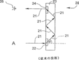
図1は、従来の技術によるホログラフィックプレートの断面図である。
図2は、もう一つの従来の技術によるホログラフィックプレートの断面図であり、本発明に従って種々の実施例に用いられる。
図3aから3cは、本発明による光学系の三つ実施例を示す断面図である。
図4aから4cは、本発明による遮光メカニズムを備えた図3aの光学系の三つの操作モードを示す断面図である。
図5は、本発明による第二のタイプの遮光メカニズムのタイプを備えた図3bに示す光学系の断面図である。
図6a及び6bは、本発明による三次元視覚のための光学系の二つの操作モードを示す断面図である。
図7a及び7bは、本発明による、近くの、そして/あるいは遠くの光景を同時に、あるいは代替的に見ることを可能にする光学系の二つの構成を示す断面図である。
図8は、本発明による三次元視覚のための眼鏡、ヘッド・セット、すなわち光学系の正面図である。
図9から図11は、従来の技術による三つのヘッドアップ・ディスプレイ(HUD)システムの断面図である。
図12及び図13は、本発明による、幾何光学の原理を用いる光学系の二つの実施例を示す断面図である。
図14aから14cは、観察者が急勾配な角度及び自然な向きで第一の光景を見ることが可能な、本発明の光学系におけるビーム・スプリッタ及び反射鏡の三つの代替的な構成を示す概要図である。
図15及び図16は、本発明による、平面光学の原理を用いる光学系の二つの実施例を示す断面図である。
図17aから17cは、図15の光学系の三つのオプション的な構成を示す断面図である。
好適実施例の説明
本発明は、少なくとも二つの光景からの光を観察者の眼へ代替的に、あるいは同時に導くための光学系に関し、異なる、あるいは単一の時間における二つ以上の光景のイメージを観察者に提供するために用いることができる。特に、本発明は、見ようとする光景に対して頭と眼との不便な位置決めを必要としない二焦点眼鏡を提供するために用いることができる。もう一つの実施例によれば、本発明は、二つの光景からの光を観察者の一方の眼あるいは両方の眼へ同時に導くための光学系に関し、観察者が一対の関連する光景を同時に見ることを可能にするものである。特に、本発明のこの実施例によって、観察者は、一方の、あるいは両方の光景の変化に同時に気付くことが可能で、そして光景の一方を他方に正確に比較することが可能になる。
図3から図8に示す本発明の第一実施例をより良く理解するために、まず、図1及び図2に示す従来の(すなわち、従来の技術による)ホログラフィックプレートの構成及び作用について述べる。
さて、図面を参照する。図1に従来の技術によるホログラフィックプレートを示す。これを下記にプレート20として言及する。プレート20は、ガラス、プラスチック(限定せず)等の光透過材から形成された本体23を含み、さらに、(本技術において回析光学素子としても知られる)入力ホログラフィック光学素子22及び出力ホログラフィック光学素子24を含む。入射光(その代表的な光線を矢印21によって示す)が入力ホログラフィック光学素子22を通過して回折される角度α、そしてプレート20を形成する材料は、(矢印21によって示すように)プレート20に入る光がほぼ完全な内反射を生じ、出力ホログラフィック光学素子24に当たり、それを介してプレート20から去る(出る)ように選択する。したがって、プレート20を用いることによって、光景Aから入力ホログラフィック光学素子22に到達する光は、出力ホログラフィック光学素子24を介して観察者の眼26に視覚認識させることが可能である。
しかし、図1の従来の技術によるホログラフィックプレート20は、ホログラフィックプレート20に入る光がプレートを出る光に対してほぼ反対の方向にある、すなわち換言すれば、光景及び観察者が図1に示すようにプレートに対して同じ関係で位置しなければならないという特徴がある。
下記にさらに詳細に説明するが、光景と観察者が共にホログラフィックプレートに対して同じ方向に配置される図1に示す従来の技術による構成は、多くの場合、本発明による種々の実施例を制限するものである。
さて、図2を参照する。これは、本発明の種々の実施例を可能にする、もう一つの従来の技術によるホログラフィックプレート30である。ホログラフィックプレート30は、図1に示す従来の技術によるホログラフィックプレート20に類似するが、決定的な違いがある。上記に説明したように、図1のプレート20を用いた場合は、観察者と、観察対象である光景との両方がプレートに対して同様な方向へ位置決めされなければならない。これとは対照的に、プレート30を用いた場合、図2に示すように、観察者は、光景を見るために、その光景の位置に対して正反対の位置をとらなくてはならない。
したがって、図1のプレート20と同様に、図2のプレート30は、ガラス、プラスチック(限定せず)等の光透過材から形成された本体33、さらに、入力ホログラフィック光学素子32及び出力ホログラフィック光学素子34を含む。入射光(その代表的な光線を矢印31によって示す)が入力ホログラフィック光学素子32を介して通過し回折される角度β、そしてプレート30が形成されるか材料は、(矢印31によって示すように)プレート30に入る光がほぼ完全な内反射を起こし、出力ホログラフィック光学素子34に当たり、それを介してプレート30を去るように選択する。
この明細書、そして特に下記の請求項の箇所において、語句「ほぼ完全な内反射」が用いられる場合、それは、ある場合には不純物、研磨不良等の原因で、光の一部が反射されないでプレートから漏れるといった限界を含む全反射を示す。これらの現象は本技術において良く知られている。実際、真の全内反射(すなわち、光が100%反射すること)は理論的なものである。しかしながら、光の数パーセントまでの損失(例えば、10%よりも少ない、5%よりも少ないことが好ましく、1%よりも少ないことがより好ましいが、0.1%以下であることが最も好ましい)は、許容可能であり、ここに用いる「ほぼ完全な内反射」の定義内に含まれる。さらに、本技術分野において既知であるが、内反射(例えば、異なる位置における)の量は電気的に制御が可能であり、このような電気的に制御されるホログラフィックプレートも、ここで用いる用語「ホログラフィックプレート」の定義内に含まれる。
しかしながら、図1に示すプレート20に対照的に、プレート30のホログラフィック光学素子32及び34は、プレートの両側に配置されている。したがって、プレート30を用いた場合、プレート30の一方の側にある光景Aは、その光が入力ホログラフィック光学素子32に到達し、出力ホログラフィック光学素子34を介して、プレート30の他方の側に位置する観察者の眼36によって観察される。
プレート20及び30は、平面的な構成を持つものとして示すが、上記に説明した内反射が妨げられないような湾曲であれば、湾曲した構成であってもよいことは、本技術において既知である。
したがって、広い意味において、ホログラフィックプレート30はつぎのものから構成される。(a)光透過材から形成された、第一側及び第二側を持つ本体。(b)本体の第一側に形成された少なくとも一つの入力ホログラフィック光学素子。光透過材、そして入力ホログラフィック光学素子の各々を、任意の方向で本体に入る入射光が回折されて、ほぼ完全な内反射を起こすように選択する。そして(c)本体の第二側に形成された少なくとも一つの出力ホログラフィック光学素子。どの出力ホログラフィック光学素子に到達する光も、例えば、図2に示すように、入射光の任意の方向とほぼ同じ方向へ本体から出る。ここに用いる「ほぼ同じ方向」とは、プレートの一方の側から入り他方の側から出ることを意味する。
ホログラフィックプレートの他の例としては、フリーゼム氏及びアミタイ氏による「光学の傾向」に述べられている(A. A. Friesem and Y.Amitai(1996)in”Trends In Optics”. A Consortini, Ed. Academic Press, NY, pp. 125-144)。特に、上記に引用した参考文献に表されたホログラフィックプレートの種々の実施例は、本文に参照として含まれている。
さて、図3aから3cを参照する。これらは、下記に光学系40として言及する、本発明による光学系の三つの代替的な実施例である。観察者は、光学系40を、少なくとも第一の光景Aと第二の光景Bとを択一的に、あるいは同時に見るために用いることができる。
この明細書、そして特に下記の請求項個所で用いる用語「光景」は、例えば、動く、そして動かない物体、ディスプレイ、画像等、肉眼で視覚できる光景を示す。さらに、ここで用いるA及びB等の二つの光景は、二つの独立した光景、重なり合う光景の両方を示し、さらに二つの僅かに異なる角度で観察した単一光景をも含む。したがって、語句「少なくとも二つの光景」が用いられた場合、これは、上記に用語「光景」が定義されたように、少なくとも二つの光景に言及するものである。
光学系40は、第一の焦点距離を持つ第一の接眼レンズ42と第二の焦点距離を持つ第二の接眼レンズ44を含む。第一のレンズ42及び第二のレンズ44は、観察者の(46と付された)一方の眼の前に互いに隣接して配置されているため、(例えば、矢印48あるいは50によって示す)単一光線は、第一のレンズ42及び第二のレンズ44の一方を介して通過する。
図3aから3c及びその後の図には、レンズ42及び44は二焦点レンズの構成要素として示されている。しかしながら、従来の二つのレンズ、すなわち二焦点レンズに融合されていないものも本発明の範囲内に含まれること、また、用語が眼科の分野で用いられるような意味で、本発明の範囲を二重焦点の構成に限定する意図はないことは同業者には明らかである。さらに、この明細書、そして特に下記の請求項個所で用語「隣接」が用いられる場合、それは、レンズ42及び44が互いに近くに配置された構成に言及するものである。したがって、観察者に対して、レンズ42及び44は、一方のレンズを通過した光が他方を通過しないという条件の下で、図3aから3cに示すように、一方が他方の下に(あるいは上に)位置しても、また、択一的に水平方向に並んで配置されても(図示せず)、あるいは他のいかなる互いに近い関係にあってもよい。
さらに、多くの用途に対して、レンズ42及び44の焦点距離は、例えば、通常の二焦点眼鏡の場合のように、一方のレンズ、例えば42が短い焦点距離を持ち近くの光景に焦点を合わせるのに適当なように、そして他方のレンズ、例えば44が長い焦点距離を持ち遠い光景に焦点を合わせるのに適当なように選択されることは、同業者には明らかである。しかしながら、下記に詳細を示すが、他の用途に対しては、例えば、光景の視差情報(すなわち、イメージの各々が、典型的に、一人の観察者の二つの眼に見えるような僅かに、そして適度に異なる角度からの光景を示す)等を提示する、イメージの三次元視覚に対しては、レンズ42あるいは44の焦点距離は、上記とは異なるように選択されるが、実際、後者の目的では、レンズ42及び44の焦点距離が等しい、あるいはほぼ等しいように選択される。
光学系40は、さらに、第一のレンズ42を通過して観察者の眼46に入る第一の光景Aからの(矢印48によって示す)入射光を導くと同時に、第二のレンズ44を通過して観察者の眼46に入る第二の光景Bからの(矢印50によって示す)入射光を導く光学装置52を含む。本発明のこの実施例によれば、光学装置52は、第一のレンズ42及び第二のレンズ44と観察者の眼46との間に配置される。
下記に説明するように、図3aから3cの各図は、光学装置52の幾分異なる構成を示すが、光学装置52が、図2に示すホログラフィックプレート30に作用において同様なホログラフィックプレート54を含む図3a及び3bに示す構成が望ましい。
ホログラフィックプレート54は、少なくとも一つ(図3aにおいては一つ、図3bにおいては二つ)の入力ホログラフィック光学素子56を含む。したがって、図3aにおいて、レンズ42を通過する入射光は、入力ホログラフィック光学素子56によって、ホログラフィックプレート54に入り、レンズ44を通過する光は、プレート54に、その外面58にほぼ直角に当たるため、ホログラフィックプレート54に直接的に入る。他方、図3bにおいては、入力ホログラフィック光学素子56は、レンズ42及び44を通過する入射光をホログラフィックプレート54に入れるように作用する。
図面には、異なる光景からの視線が平行に示されているが、本発明の範囲を平行な視線だけに限定する意図はなく、本発明は、平行である、あるいは平行でないに関わらず、如何なる二つの光景あるいは視線に対しても適用が可能である。
しかしながら、これらの場合、ホログラフィックプレート54は、さらに、少なくとも一つの出力ホログラフィック光学素子60を含む。出力ホログラフィック光学素子60は、ホログラフィックプレート54に入った光が、ホログラフィックプレート54を去って、観察者の眼46に到達することを可能にするものである。ホログラフィックプレート54が光を受けない部分を、図3aに示すように、不透明なカバー57で覆うことが好ましい。
図3cに示すように、光学装置52は、択一的に、光景A及びBのいずれ、あるいは両方からの入射光を観察者の眼46へ導く反射光学素子62のセット(例えば、幾何光学の技術分野において良く知られる鏡、プリズムあるいはそれらの組合せ)を含んでもよい。実際、図3cにおいては、光景Aからの入射光は反射光学素子62によって観察者の眼46へ導かれるが、光景Bからの入射光は第二のレンズ44通過した後、4直接的に眼46へ到達する。しかしながら、さらに、図3bに類似する反射光学素子の同様なセットを、光景Bからの入射光を観察者の眼46へ導くために用いてもよい。
現在は、例えば、図3a及び3bに実証する平面光学素子の製造及び作動は、図3cに実証する非平面的な(すなわち幾何学的な)光学素子と比較した場合、かなり制限が少ないため、平面光学を利用する実施例が好ましい。平面光学、特にホログラフィック要素の形成手段に関する詳細については、例えば、フリーゼム氏及びアミタイ氏による「光学の傾向」及びジュルゲン・ジョンズ氏及びスーザン・J・ウォーカー氏による「薄膜付着によって製造された回折マイクロレンズの二次元アレイ」に述べられている(A. A. Friesem and Y. Amitai(1996)in”Trends In Optics”. A Consortini, Ed. Academic Press, NY, pp. 125-144; Jurgen Johns and Susan J. Walker(1990)Two-dimensional array of diffractive microlenses fabricated by thin film deposition, Applied Optics 29:931-936)。
本発明の好適実施例においては、光学系40は、図8に示す眼鏡200に用いられ、従来の技術における二焦点眼鏡を用いることに関連するものとして、頭を動かさずに、あるいは眼が向けられた方向を変えないで近くの、そして遠くの光景を見ることを可能にする。このため、図3a及び3bに示す構成のいずれかの二つの光学系40を、観察者の眼の各々の前に一つの光学系40が配置されるように、従来の眼鏡フレームであるフレーム202に取り付ける。
この場合、光学系40の各々は、図3aから3cに示すように、近い光景Aを見るための短い焦点距離を持つレンズ42としての下部構成要素と、遠い光景Bを見るための長い焦点距離を持つレンズ44としての上部構成要素とを含む二焦点レンズから構成される。光学系40の各々のレンズ42及び44は、眼科の技術において既知であるが、特定な人の視覚異常及び視覚限界を調整(補正)するように選択する。観察者がフレームを身につけるため、光景A及びBの両方からの光が観察者の眼に到達する。それでも、観察者の眼がリラックスしているとき、すなわち観察者の眼が遠距離の視覚に適応しているときは、光景Aには焦点が合っておらず、光景Bが観察者の網膜上にほぼ集束する。他方、観察者の眼が近い物を視覚するように焦点が合っているとき、すなわち観察者の眼が短距離の視覚に適応しているときは、光景Bには焦点が合っておらず、光景Aが観察者の網膜上にほぼ集束する。いずれの場合も、観察者には、一方の光景が集束して、他方がピントがぼけて見える。観察者の脳は、焦点はずれの光景を無視することを学ぶため、トレーニングの後には、焦点が合った光景のイメージのみを認知するようになる。したがって、従来の技術による二焦点眼鏡が用いられるモードとは対照的に、長距離の視覚から短距離の視覚に変えるとき、あるいはその逆のときは、観察者は、単に眼の焦点を変えることが必要とされるため、頭の位置及び眼の方向を一定にを保つことが可能である。
現在、非常に高い屈折率を持つ光透過材が知られているため、眼鏡及び他の光学装置に用いるレンズの厚さは低下し、それらの湾曲は平らになっている。このような小さな湾曲のレンズは、(眼に面する)内面に、僅かに湾曲するホログラフィックプレートを接着することができるので、本発明による眼鏡に用いるのに非常に適している。
同様に、図3aから3c、それ以降の図に示す構成に従う光学系40には、二つ以上のレンズを用いることが可能である。この場合、上記に用語「光景」を定義したように、三つ以上の光景からの光を同時に、択一的に、あるいは対として観察者の眼へ導いてもよい。
図4aから4cを参照する。本発明の好適実施例によれば、光学系40は、さらに遮光メカニズム70を含む。遮光メカニズム70は、少なくとも観察者が選択する任意の時間に渡って、第一及び第二の光景A及びBの一方の光が観察者の眼46に到達しないように光を遮るためのものである。図4aから4cにおいては、図3aに示す光学系40の構成が、さらに遮光メカニズム70を含むように作り直されている。遮光メカニズム70は光ブロッカ72を含み、このブロッカは三つの操作モードを持つことが好ましい。
図4bに示す第一の操作モードでは、光ブロッカ72は、光景Aからの光が観察者の眼46に到達しないように光を遮って配置されている。
図4cに示す第二の操作モードでは、光ブロッカ72は、光景Bからの光が観察者の眼46に到達しないように光を遮って配置されている。
図4aに示す第三の操作モードでは、光ブロッカ72は、観察者の眼46に対して光景A及びBのどちらの光をも遮らないように配置されている。このため、第三の操作モードでは、光学系40は、本質的に、上記図3aで説明したように機能する。
したがって、図4bに示す第一の操作モードでは、観察者の眼46には光景Bだけが映り、図4cに示す第二の操作モードでは、観察者の眼46には光景Aだけが映る。しかし、図3aに示す第三の操作モードでは、観察者の眼46には光景A及びBの両方が映る。
本発明による光学系のこの実施例は、例えば、上記に説明したように焦点はずれの光景を無視できない観察者に適する。このような観察者は、単に一つの操作モードからもう一つの操作モードへと、遮光メカニズム70に沿って光ブロッカ72を移動させることによって、光景を選択して見ることができる。
同業者には明らかであるが、(i)遮光メカニズム70は、図3aから3cを参照して説明した光学系40のどの構成にでも用いることが可能である。(ii)遮光メカニズム70は、レンズ40及び42と光学装置52とに相対的にどの位置にでも配置することが可能である。例えば、遮光メカニズム70をレンズ42及び44の前に、あるいは光学装置52と観察者の眼46との間に配置してもよい。そして(iii)上記の三つの操作モードのうち、単に二つの操作モードの組合せを持つ遮光メカニズム70も、ある観察者に対しては、あるいは用途によっては有用である。
図5に、図3bに示す光学系40の構成を、もう一つのタイプの遮光メカニズム70を含むように作り直す。図5の遮光メカニズム70は、各々レンズ42及び44に対して取り付けた光ブロッカ72a及び72bを含む。ブロッカ72aそして/あるいは72bの各々を回転することによって、光景Aそして/あるいはBからの光が、各々観察者の眼46に到達することが妨げられる。
図8に示す本発明のもう一つの好適実施例においては、光学系40は、単一光景の、二つの角度からの二つのイメージA及びBの三次元視覚を目的としたヘッド・セット300に用いられる。この場合、イメージA及びBは単一光景の視差情報を含む。本発明のこの実施例の説明においては、イメージAからの光は、上記に説明した光景Aからの光として作用し、イメージBからの光は、上記に説明した光景Bからの光として作用することに注意すべきである。
このため、二つの光学系40(図3a及び3bに示す構成の一方を用いることが好ましい)を適当なフレーム、例えば従来のヘッド・セットフレーム(図示せず)内に取り付け、光学系40を観察者の各々の眼の前に配置する。この場合、光学系40の各々は、任意の比較的に短い焦点距離を持つレンズ42を第一の構成要素として、同様な焦点距離を持つレンズ44を第二の構成要素として含む。この場合、両レンズは拡大及び照準レンズであることが好ましい。しかし、この場合、レンズ42及び44は、必ずしも視覚異常を調整(補正)するものとして用いられるものではない。両光学系40の遮光メカニズム70を収容するフレームを観察者が身につけると、一方の眼がイメージAからの光だけを受け、他方の眼がイメージBからの光だけを受けるため、観察者は、その光景を三次元に視覚する。
実際、三次元視覚の目的では、光学系40が全くレンズを含まないような構成にしてもよい。このような単純な光学系を、下記に光学系40’として、図6a及び6bに二つの操作モードを示す。光学系40’は、図3bに示す光学系40の上記すべての構成要素を含むが、レンズを欠いている。観察者は、光学系40’用いて、同時に、第一のイメージAを一方の眼、例えば46で、そして第二のイメージBを他方の眼、例えば46’で見ることができる。したがって、光学系40は、第一のイメージAからの(矢印48によって示す)入射光を観察者の一方の眼46へ、そして同時に、第二のイメージBからの(矢印50によって示す)入射光を観察者の他方の眼46へ導くための光学装置52を含む。図6a及び6bに示す望ましい構成においては、光学装置52はホログラフィックプレート54を含む。ホログラフィックプレート54は、二つの(図3bのものに類似する)入力ホログラフィック光学素子56を含むことが好ましい。入力ホログラフィック光学素子56は、入射光がホログラフィックプレート54に入ることを可能にするためのものである。本発明のこの実施例のようにレンズが用いられない場合は、入力ホログラフィック光学素子56は、対応するイメージAあるいはBに視野を限定するように選択されることが好ましい。ホログラフィックプレート54は、さらに、少なくとも一つの出力ホログラフィック光学素子60を含む。出力ホログラフィック光学素子60は、ホログラフィックプレート54に入った光がホログラフィックプレート54から去り、観察者の眼46及び46’に到達することを可能にするためのものである。三次元視覚のために、光学系40’は、さらに、遮光メカニズム70を含む。遮光メカニズム70は、第一及び第二のイメージA及びB内の視差情報のタイプに応じて、イメージA及びBからの各々の光が、観察者の各々の眼46及び46’に到達することを遮るものである。好適実施例においては、遮光メカニズム70は、光ブロッカ72を含み、図4aから4cに関して上記に説明したような三つの操作モードを持つことが好ましいが、二つの操作モードを図6a及び6bに示す。
したがって、図6aに示す第一の操作モードにおいては、観察者の眼46にはイメージBだけが見え、図6bに示す、第二の操作モードにおいては、観察者の眼46’にはイメージAだけが見える。
観察者に対して、予め定めたやり方でイメージA及びBを配置するなら、すなわち、左のイメージ(すなわち、光景に対して左の角度のイメージ)、例えばイメージAが観察者の左眼、この場合は眼46’で見えるように配置し、そして右のイメージ(すなわち、光景に対して右の角度のイメージ)、例えばイメージBが、観察者の右眼、この場合は眼46で見えるように配置するならば、光学系40’は、遮光メカニズム70を含まないで、入力ホログラフィック光学素子56を一つだけ含むように単純化することも可能である。この場合、この入力ホログラフィック光学素子は、図6aに示す第一のケースとして、イメージBからの(矢印50によって示す)光が眼46に到達するように、そして、図6bに示す第二のケースとして、イメージBからの(矢印48によって示す)光が眼46’に到達するように配置される。
したがって、本発明によれば、光景を観察者が三次元として視覚できる光学系が提供される。この場合、光景は第一のイメージ及び第二のイメージとして提示され、第一及び第二のイメージの各々は光景の視差情報を含む。この光学系は、各々が光透過材から形成された本体を持つ第一及び第二のホログラフィックプレートから構成され、各々は、さらに、本体の第一側に形成された少なくとも一つの入力ホログラフィック光学素子を含む。本体を形成する材料及び入力ホログラフィック光学素子の各々は、本体に入った任意の方向を持つ入射光が回折され、上記に用語「内反射」を定義したように、ほぼ完全な内反射を生じるように選択する。第一及び第二のプレートの各々は、さらに本体の第二側に形成された少なくとも一つの出力ホログラフィック光学素子を含むため、出力ホログラフィック光学素子に到達する光は、本体から、入射光の任意の方向とほぼ同様な方向に出る。この光学系は、第一のホログラフィックプレートによって第一のイメージからの光だけが観察者の一方の眼に到達するように、そして第二のホログラフィックプレートによって第二のイメージからの光だけが観察者の他方の眼に到達するように形成される。これを可能にするために、ホログラフィックプレートの各々は、さらに遮光メカニズムを含むことが好ましい。
本発明のもう一つの実施例においては、光学系40を、観察者の視野外の情報を視野内にもたらすために用いることも可能である。例えば、眼が前方の道路(空)に向いた自動車の運転手(あるいは航空機のパイロット等)は、前方の道路(空)と情報パネルとの両方を同時に視覚するために、そして/あるいは運転手(パイロット)の視野の、通常下方あるいは上方に位置する情報を映すために、眼の前に一対の光学系40を身につけることができる。上記の三次元視覚の実施例のように、この場合も、レンズはオプション的なものであり、不可欠なものではない。
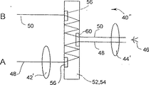
さて、図7a及び7bを参照する。本発明のもう一つの好適実施例によれば、下記に光学系40”として述べられる光学系が提供される。光学系40”を用いることによって、頭を動かさずに、あるいは眼の方向を変えないで、近くの、そして遠くの光景の両方を見ることを可能にする、例えば、図8に示す200と付された眼鏡を提供することができる。この眼鏡は、各接眼レンズが僅かに一つの特注レンズから構成されるため、光学系40の種々の構成に基づく眼鏡に比べ(二つの特注レンズ)、製造が容易である。
図7a及び7bに、本発明による光学系40”の二つのオプション的な実施例を示す。観察者は、光学系40”を、近くの光景Aと遠くの光景Bとを択一的に、あるいは同時に見るために用いることができる。光学系40”は、通過する光の照準を正す拡大照準接眼レンズ42’を含む。拡大照準レンズ42’は(例えば、読むのに適する25から40cmの範囲の)比較的に短い焦点距離を持つことが好ましい。拡大照準レンズ42’は、基本的な光学素子として市販されている従来のタイプのものであることが好ましい。したがって、これは特注品ではない。
光学系40”は、近くの光景Aからの(矢印48によって示す)入射光を、拡大照準レンズ42’を介して観察者の眼46に、そして同時に、遠くの光景Bからの(矢印50によって示す)入射光を観察者の同じ眼46に導くために、さらに、ホログラフィックプレート54の形態で光学装置52を含むことが好ましい。光学装置52は、図3cに示す要素62等の反射光学素子を含んでもよいが、この構成は、現時点では、古典幾何光学に比べて平面光学の方が利点が多いため、好ましくない。
ホログラフィックプレート54は、少なくとも一つの(図7aにおいては一つ、図7bにおいては二つの)入力ホログラフィック光学素子56を含む。したがって、図7aにおける入力ホログラフィック光学素子56は、近くの光景Aからの、レンズ42’を通過してホログラフィックプレート54に入る入射光を受け入れるためのものである。この場合、光景Bからの光は、プレート54の外面58にほぼ直角に当たるため、直接的にホログラフィックプレート54に入る。他方、図7bにおける入力ホログラフィック光学素子56は、光景A及びBの両方からの入射光をホログラフィックプレート54に受け入れるためのものである。
しかし、どちらの場合も、ホログラフィックプレート54は、さらに、少なくとも一つの出力ホログラフィック光学素子60を含む。出力ホログラフィック光学素子60は、ホログラフィックプレート54に入った光を、ホログラフィックプレート54から放ち、観察者の眼46に到達させるためのものである。
光学系40”は、さらに、典型的に長い焦点距離を持つ補正接眼レンズ44’を含む。補正レンズ44’は、遠距離視覚異常を調整する(補正する)ためのもので、特定の観察者の特定の眼46に調整される。補正レンズ44’は、観察者の眼46と出力ホログラフィック光学素子60との間に位置している。光景Aそして/あるいはBから補正レンズ44’に到達する光は照準が正しい状態にある。これは、近くの光景Aからの光が拡大照準レンズ42’によって照準が正され、遠くの光景Bからの光が自然にほぼ照準が正されるためである。
上記に説明した光学系40”の構成によれば、短距離及び遠距離の両方の視覚異常に苦しむ観察者が、近くの光景A及び遠くの光景Bを快適に同時に、あるいは択一的に見るためには、特注レンズ(すなわち、レンズ44’)が一つだけ要求される。光学系40のように、光学系40”にも、近くの光景A及び遠くの光景Bの視覚を容易にするために、(例えば、図4aから4cに示す遮光メカニズム70に類似する)遮光メカニズムを補ってもよいことは明らかである。したがって、光学系40”には、光学系40について上記に説明したすべての利点がある。さらに、光学系40では二つの特注レンズ(例えば、図3a及び3b、そして図4aから4cのレンズ42及び44)が必要とされるのに対し、光学系40”には、特注レンズ(すなわち、レンズ44’)が一つだけであるという、もう一つの利点がある。
本発明の第二実施例による光学系は、光景からの受動光を用いるもので、ヘッドアップ・ディスプレイ(HUD)システムとは対照的に、システムの一部として能動光(すなわち、ディスプレイ)を用いることはない。
図面の図12から図17に示す本発明の第二実施例をより良く理解するために、ここで、図9から図11に示す従来の(すなわち、従来の技術による)ヘッドアップ・ディスプレイ(HUD)システムの構成及び作動について述べる。
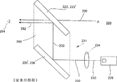
下記にシステム220と言及する従来のHUDシステムは、結合器として機能するビーム・スプリッタ222を含む。結合器222は、遠くの光景Aからの、視線226によって示す照準が正された受動光が本質的に何の影響も受けずに観察者の眼254に到達するように、観察者の眼254に相対的に配置される。HUDシステム220は、さらに、アクティブなディスプレイ装置228を含む。この装置228は通常ブラウン管(CRT)であって、Dと付したディスプレイを提示する。このため、装置228は、視線230によって示す(通常、照準が正されていない)能動光を発する。下記に述べるが、システム220は、(i)視線232によって示す光の照準を正す、そして(ii)この平行光232を結合器222へ、そして、そこから観察者の眼254へ導くことが可能な光学装置231を含む。したがって、観察者は、光景A及びディスプレイDの両方からの平行光を同時に見る。
従来のHUDシステム220は、いくつかの構成に形成することが可能であり、三つの例を図9から図11に示す。
図9に示すように、光学装置231は照準レンズ234を含む。図9の構成においては、装置228及びレンズ234は、装置228から発した、照準が正されていない能動光230が照準レンズ234を通過し、そこで照準が正され、しかし方向はほとんど変化せずに結合器222に向かい、そして結合器222によって反射されて観察者の眼254へ導かれるように、共直線的に配置される。
図10に示すように、光学装置231は、前記のものと同様に照準レンズ234を含み、さらに反射鏡(例えば、鏡あるいはプリズム)236を含む。図10に示す構成では、装置228及びレンズ234は、装置228から発した照準が正されていない能動光230が照準レンズ234を通過して照準が正され、232によって示すこの平行光が反射鏡236に到達し反射されて結合器222に向かい、次に結合器222によって反射されて観察者の眼254へ導かれるように、共直線的に配置される。レンズ234及び反射鏡236の位置は、光がまず反射されてから照準が正されるように変えてもよいこと、また、システム220の他の構成要素に対して装置228が、これとは異なって配置される場合は、装置228から結合器222へ光を導くために、さらに反射鏡を追加してもよいことは明らかである。
図11に示すように、光学装置231は、先に説明した図10に示す第二の構成の照準レンズ234及び反射鏡236によって達成されるものと同様な照準と反射との組合せ効果を提供するための照準反射鏡238を含む。図11に示す構成では、装置228及び照準反射鏡238は、装置228から発した、照準が正されていない能動光230が、照準反射鏡238によって反射されると同時に照準が正され、232によって示すこの平行光が、照準反射鏡238のカーブに適応した照準結合器である結合器222に到達し、次に、その光が照準結合器222によって反射されて観察者の眼254へ導かれるように配置される。システム220の他の構成要素に対して装置228がこれとは異なって配置される場合、装置228からの光を結合器222へ導くために、さらに反射鏡を追加してもよいことは明らかである。
ある場合には、システム220のための、上記に説明した光学素子はすべて、上記に特定したように各面が機能する表面を持つ単一の光学素子に含ませることができる。したがって、例えば、図10に示す構成では、結合器222及び反射鏡236は、(破線で示す)単一のエレメント240の二つの面であってもよい。この場合、光は、これを通って、反射面236’から結合面222’へ進む。この方向のHUDシステムは、例えば、JP497193(要約)に開示されている。
従来の技術によるHUDシステムのいくつかは据置型であるが、システムがいつも観察者の眼の前に位置するように、ヘッド・セット、ヘルメット等に(少なくとも部分的に)取り付けたものもある。しかしながら、すべての従来の技術によるHUDシステムは、受動光を介して視覚により認識される一つの光景と、能動光を介して視覚により認識される一つのディスプレイとの同時のプレゼンテーションに限定される(用語「受動光」及び「能動光」は上記背景の個所で定義している)。現在既知であるHUDシステムで、二つの光景の同時視覚を、本発明の基礎である上記に定義した意味において目指すものは全く存在しない。換言すれば、HUDシステムでは、観察者の各々の眼は、観察者の眼に到達する受動光によって形成される一つの実像と、観察者の眼に到達する能動光によって形成される一つの虚像とを同時に視覚により認識する。多くの場合、両イメージからの光は、観察者の眼がかなりリラックスした(すなわち、近距離視覚に適応していない)状態で、両イメージがはっきりと見えるように、自然に、あるいは光学的に、ほぼ、あるいは完全に照準が正される。
本発明による光学系の原理及び作用については、次の図面と、その説明から良く理解することができる。
さて、図12及び図13に、下記に光学系250として言及する本発明による光学系のいくつかの実施例を示す。
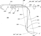
光学系250は、観察者が、A(あるいはA’)によって示す第一の光景と、Bによって示す第二の光景とを同時に見ることを可能にするためのものである。両光景A(あるいはA’)及びBは、用語「光景」が上記背景の個所で定義されているように、受動光を介して観察者が視覚により認識するものである。ここに説明する光学系250は、観察者の一つの眼に使用するためのものである。構成要素が最も少ない構成において、光学系250は、観察者の頭に光学系250を取り付け、観察者の眼254の前に光学系250を配置するためのヘッド・アレンジメント252を含む。ほとんどの実施例においては、観察者の眼の各々に対して一つ、合計二つの光学系250を用いる。これらの場合、これら二つの光学系の他の構成要素を係合させるには、一つのヘッド・アレンジメント252で十分である。図12及び図13では、ヘッド・アレンジメント252は、眼鏡の耳どめに類似するように示されているが、多くの他の構成が可能であり、本技術分野で良く知られる例えば、ヘッド・セット、ヘルメット等(限定せず)、あるいは観察者の眼の前に近づけて光学系250をしっかり固定することができる他の構成でもよい。
同業者には明らかであるが、光学系250の構成要素が大きい場合、光学系250は、使用中に観察者の頭に係合しないタイプのものでもよい。この場合、光学系250は、ヘッド・アレンジメントを含まず、その代わり、ここに説明するその他の構成要素は、適当なハウジング(図示せず)内に直接的に、あるいは間接的に係合されることが好ましい。その大きさに応じて、単一の光学系250が観察者の両眼に対して同時に作用してもよい。
構成要素が最も少ない構成でも、光学系250は、視線257によって示す第一の光景Aからの光と、視線258によって示す第二の光景Bからの光との両方が観察者の眼254の中へ同時に導かれるように配置されるビーム・スプリッタ256を含む。したがって、ビーム・スプリッタ256が結合器として機能する。
好適実施例においては、ビーム・スプリッタ256は、観察者が彼の頭を動かした場合に観察者が、第一の光景A(あるいはA’)及び第二の光景Bを見るのに光学系を調整できるように、そして観察者が、同時に見るもう一対の光景(図示せず)を選択できるように、ヘッド・アレンジメント252に対して可動性(例えば、移動、回転、あるいは両方)がある。ビーム・スプリッタ256を動かすには、例えば、ヘッド・アレンジメント252にビーム・スプリッタ256を連結する第一のヒンジ259が有効である。
多くの場合、第一の光景A(あるいはA’)は近くの光景で、第二の光景Bは遠くの光景である。ここに用いる用語「近くの光景」は、観察者が近くの光景を見るために、眼の焦点を合わせる(適応させる)必要がある場合、観察者から特定な距離内に位置する光景を示す。したがって、近くの光景は、通常、観察者から、数センチメートルから数メートルまでの範囲内に位置する。ここに用いる用語「遠くの光景」は、観察者が遠くの光景を見るために、眼の焦点を合わせる(適応させる)必要がほとんどないような観察者から特定な距離内に位置する光景を示す。したがって、遠くの光景は、通常、観察者から例えば5から10メートル、あるいは例えば100から1000メートルの範囲、あるいはもっと遠くに位置する。第一の光景A(あるいはa’)が近くの光景で、第二の光景Bが遠くの光景である場合は、遠くの光景Bからの光は、(かなり遠くから到達するので)自然にほぼ照準が正されるが、近くの光景A(あるいはA’)からの光は照準が正されない。このことは、観察者が両光景をはっきりと同時に見るうえで問題である。その理由は、任意の時点における眼254は、近くの光景A(あるいはA’)を見るために焦点が合わされて、遠くの光景Bをはっきりと見ることができない状態にあるか、あるいは択一的に、遠くの光景Bを見るためにリラックスして、近くの光景A(あるいはA’)をはっきりと見ることができない状態にあるかのいずれかであるためである。したがって、図12に示すように、本発明の好適実施例においては、光学系250は、さらに、照準レンズ260を含む。このレンズは、近くの光景A(あるいはA’)からの光の照準を、ビーム・スプリッタ256に到達する前に正すためのものである。照準レンズ260は、ヘッド・アレンジメント252(図示せず)によって(例えば、ビーム・スプリッタ256等の光学系250の他の構成要素を介して)直接的にあるいは間接的に支持される。図13に示すように、照準レンズを介して近くの光景A(あるいはA’)からの光の照準を正す代わりに、ビーム・スプリッタ256を照準ビーム・スプリッタ256’として選択することによって、光の照準を正すことができる。
しかしながら、光景A(あるいはA’)及びBが共に遠くの光景である場合、両光景A(あるいはA’)及びBからの光は、自然に照準がほぼ正される。この場合、照準を正す必要はないが、光学系250が多目的に使用できるように、なおかつ照準合わせを行うことが好ましい。
さらに、第一の光景A(あるいはA’)及び第二の光景Bが共に近くの光景である場合、光景A(あるいはA’)及びBからの光は照準が正されない。この場合、いくつかの用途に対しては、光学系250が、さらに、第一の光景A(あるいはA’)からの光の照準を正すための第一の照準レンズ260(図12)あるいは照準ビーム・スプリッタ(図13)と、第二の光景Bからの光の照準を正すための第二の照準レンズ262との両方を含むことが好ましい。この場合、第二の照準レンズ262は、直接的にあるいは間接的にヘッド・アレンジメント252によって支持される。
さらに、他の用途に対しては、全く照準合わせを行わないことが好ましい。例えば、観察者が二つの光景からの光を同時に受けることを望みながら、一方の光景のみにはっきりと焦点を合わせたい場合、他方の光景に焦点が合ってなくても、その光景に変化が生じたときに観察者の注意を引き付けることができる。
しかしながら、好適実施例においては、観察者に視覚により認識される前に、光学系250を通過するすべての光の照準を正すために、ビーム・スプリッタ256と観察者の眼254との間に位置した照準レンズ267が用いられる。
第一の光景A(あるいはA’)あるいは第二の光景Bは、観察者に対して任意の位置に存在するため、例えば、第一の光景はAあるいはA’に位置してもよいし、また、観察者が、ビーム・スプリッタ256から反射した後の第一の光景Aを見ると、光景は逆さまの方向で視覚されるため、本発明の好適実施例においては、光学系250は、さらに、少なくとも一つの反射鏡264を含む。反射鏡264の各々は、直接的にあるいは間接的にヘッド・アレンジメント252によって支持される。図12及び図13に示すように、ヘッド・アレンジメント252によって間接的に支持された単一の反射鏡264が用いられる。この単一の反射鏡264は、ヘッド・アレンジメント252によって支持されたビーム・スプリッタ256に中性光学素子266を介して連結される。したがって、反射鏡264は、第一の光景A’からの光をビーム・スプリッタ256に導くためのものである。しかしながら、ある場合には、図13に示すように、反射鏡264自体が光の照準を正することが可能なことが好ましい。このため、照準反射鏡264’を選択してもよい。
多くの用途ににおいては、観察者が頭を移動させて第一の光景A(あるいはA’)及び第二の光景Bを見るときに観察者が光学系250を調整することができるように、そして観察者が、第一あるいは第二の光景と共に同時に見るための少なくとも一つの置換光景(図示せず)を選択できるように、反射鏡264及びビーム・スプリッタ256の少なくとも一つがヘッド・アレンジメント252に対して可動であることが重要である。このため、光学系250は、さらに、反射鏡264と中性光学素子266との間を連結する第二のヒンジ268を備えてもよい。
本発明のもう一つの実施例においては、ビーム・スプリッタ256及び反射鏡264は、点線272によって示す容量を持つ単一の光学素子270の各々第一面256”及び第二面264”として形成される。
これまで説明した光学系250は、(視覚異常がない)正常な視力を持つ観察者に適しているが、光学系250は、視覚異常がある観察者も使用することができる。例えば、眼のレンズ及び角膜の力が強すぎること、そして/あるいは眼球が長すぎることから生じる焦点に関する視覚異常である近視の場合は、正の集束能が大きすぎるために遠くの物のイメージが網膜の前に集束し、はっきりと見ることができないため、発散レンズを選択して、近視眼が焦点を合わせることができる最も遠い点にイメージを形成するようにする。他方、眼の屈折要素が弱すぎること、そして/あるいは眼球が短すぎることから生じる近視の正反対である遠視の場合は、遠くの物のイメージが(眼がリラックスしているときに)網膜の背後に形成される。したがって、遠視は収束レンズによって補正する。近視及び遠視は、遠くの物を見る場合の視覚異常である。他方、近くの物を見る場合の視覚異常の一つであり、多くの場合、読む能力を損なう老視は、典型的に、年齢の経過と共に眼レンズが硬化した結果として生じ、近くの物に対して眼の焦点を合わせる(適応させる)能力が制限されてしまう。したがって、老視は、快適に読むことができるように、収束レンズによって補正する。従来の眼鏡は、典型的に、観察者の眼の前の適当な位置に眼鏡を支持するためのフレームと、フレーム内に設けた、観察者の眼の各々に対して一つずつ、合計二つのレンズとを含み、各レンズは、特定な眼視覚異常を補正する焦点特性を持つ。
眼鏡が必要な人に対しては、ヘッド・アレンジメント252が眼鏡のフレームに取り付けられるアタッチメント(図示せず)として、光学系250を構成してもよい。択一的に、光学系250は、さらに、観察者の視覚異常を補正するための矯正光学レンズ274を含んでもよい。この矯正光学レンズは、ビーム・スプリッタ256と観察者の眼254との間に配置し、ヘッド・アレンジメント252(図示せず)によって直接的にあるいは間接的に支持する。
上記の通り、これまで説明した光学系250は、観察者の一方の眼、例えば眼254に使用するものであるが、多くの場合、観察者の眼の各々に対して、独立した光学系250を補うことが好ましい。このため、本発明の好適実施例によれば、観察者が第一の光景A(あるいはA’)及び第二の光景Bを同時に見ることが可能なヘッド・セット(例えば、ヘルメット)が提供される。このヘッド・セットは、上記の実施例における二つの光学系250を含み、観察者の眼の各々の前に一つずつ光学系250が配置される。
観察者の眼の各々が、異なる光景を見ることができるほうが望ましい場合、ヘッド・セットは、単に、観察者の一方の眼、例えば眼254の前に配置された一つの光学系250を含むだけでもよい。この場合、両眼が一つの光景、例えば第二の光景Bに向けられ、そしてビーム・スプリッタ256がほぼ反射面256”’としてのみ機能するなら、すなわち、第二の光景Bからの光をほとんど通さず、第一の光景A(あるいはA’)からのほとんどの光を反射するなら、観察者のその一方の眼(254)が第二の光景Bに向けられていても、第一の光景A(あるいはA’)からの光が入るため、眼254は光景A(あるいはA’)を見るが、このとき同時に、他方の眼は光景Bを直接的に見る。
これと全く同じ効果を、観察者の眼の各々に対して一つずつ二つの光学系250を用いる上記のヘッド・セットを使用しても得ることができる。しかし、この場合は、視線258が観察者の一方の眼によって、また視線257が他方の眼によって視覚されないように遮る遮光メカニズムを用いることが必要である。遮光メカニズム(例えば、光シャッタ)については、本文中で説明したが、本技術分野においても良く知られている。
さて、図14a及び14bを参照する。ディスプレイ(例えば、CRTディスプレイ)からの光を、結合器として機能するビーム・スプリッタへ導く反射鏡を含むHUDシステムにおいては、場合によって、ディスプレイは、逆さまに、あるいは真のディスプレイの鏡像として表示される。HUDシステムでは、このことは、ほとんど問題ではない。ディスプレイ自体を変えることができる(例えば、逆さまに、あるいは鏡像として表示できる)ため、観察者は、ディスプレイを正常な状態(例えば、右側が上にある自然なイメージ)で見ることが可能である。
しかし、この効果は、受動光による光景を見るために用いる光学系にとっては深刻な問題である。なぜなら、観察者は、光景に対して、ディスプレイを見るときのようなコントロールを持たないためである。
このため、本発明の好適実施例においては、第一の光景A’の光景が観察者に自然な状態で見えるように、ビーム・スプリッタ256及び反射鏡264を第一の光景A’に対して、また観察者の眼254に対して配置する。このような構成のいくつかを図12及び図13に概略的に示し、上記に説明した。しかしながら、第一の光景A’を自然な状態で見ることを可能にする図12及び図13の構成は、地平線に対して浅い角度(例えば、俯角0から70度)に位置する第一の光景、例えば第一の光景A’を見ることを可能にするが、地平線に対して急勾配な角度(例えば、俯角70から90度)に位置する第一の光景、例えば第一の光景Aを見ることを制限する。
図14aから14cに示す構成は、ビーム・スプリッタ256の上方に反射鏡264を配置し、ビーム・スプリッタ256の低い方を観察者の眼254に近づけている。したがって、これらの構成は、急勾配な角度にある第一の光景(例えば、光景A)を見ること、そして自然な状態で光景を見ることを可能にする。
光学系250は、一対の関連する光景を同時に見るのに適しており、そのために用いることができる。ここに言及する関連する光景とは、観察者に対して異なる位置にある光景のことであり、したがって、光学器械を使用せずには、はっきりと同時に見ることは不可能である。しかし、このような光景を同時に見ることには利点がある。このような光景の対としは、限定せずに次のものを含む。ノートと黒板、ノートと講師、ノートとスクリーン、絵と描画対象物、キーボードとスクリーン、印刷物とスクリーン、印刷物と前方の道路、そして印刷物と前方の空。リストした光景の対については、上記背景の個所で詳しく述べている。
さらに、図12から図14を参照する。本発明によれば、観察者が第一の光景及び第二の光景を同時に見ることを可能にするための方法が提供される。この場合、第一及び第二の光景の両方は受動光を介して観察者に視覚される。
好適実施例によれば、この方法は次のステップを含む。(a)第一の光景Aからの光と第二の光景Bからの光との両方を観察者の眼254に同時に導くように配置されたビーム・スプリッタ256を観察者に提供する。ビーム・スプリッタ256は、観察者が頭を動かした場合、第一の光景A(あるいはA’)及び第二の光景Bを見ることが可能なように観察者が光学系を調整することができるよう、また観察者が他の二つの光景(図示せず)を選択して同時に見ることができるように可動性であることが好ましい。第一の光景A(あるいはA’)が近くの光景で、第二の光景Bが遠くの光景である場合、遠くの光景Bからの光は自然に照準がほぼ正される。この場合、この方法は、さらに、近くの光景A(あるいはA’)からの光の照準を正すための照準レンズ260を観察者に提供するステップを含むことが好ましい。第一の光景A(あるいはA’)及び第二の光景Bが共に遠くの光景である場合には、光景A(あるいはA’)及びBからの光は自然に照準がほぼ正される。さらに、第一の光景A(あるいはA’)及び第二の光景Bの両方が近くの光景である場合は、どちらの光景からの光も照準が正されていない光である。この場合は、この方法は、さらに、第一の光景A(あるいはA’)からの光の照準を正すための第一の照準レンズ260を観察者に提供するステップを含むことが好ましい。そしてさらに、第二の光景Bからの光の照準を正すための第二の照準レンズ262を観察者に提供するステップを含むことが好ましい。
好適実施例によれば、この方法は、さらに、第一の光景A’からの光をビーム・スプリッタ256へ導くための少なくとも一つの反射鏡264を観察者に提供するステップを含む。観察者が頭を動かす場合、観察者が第一の光景A’及び第二の光景Bの視覚を調整できるように、また観察者が、第二の光景と共に同時に見るための少なくとも一つの置換光景(図示せず)を選択できるように、反射鏡264及びビーム・スプリッタ256の少なくとも一つが、互いに対して可動性があることが好ましい。好適実施例においては、ビーム・スプリッタ256及び反射鏡264は、体積を持つ単一の光学素子270の各々第一面256”及び第二面264”として形成される。本発明の好適実施例によれば、反射鏡264は照準反射鏡264’であり、ビーム・スプリッタ256は照準ビーム・スプリッタ256’である。このため、第一の光景A’からの光は、ビーム・スプリッタ256’に到達する前に照準反射鏡によって照準が正される。
本発明の方法の好適実施例によれば、ビーム・スプリッタ256及び反射鏡264は、第一の光景Aが急勾配な角度で、そして自然な状態で見られるように、第一の光景Aに対して、また観察者の眼254に対して配置される。
本発明の方法のもう一つの好適実施例によれば、この方法は、さらに、観察者の視覚異常を補正する矯正光学レンズ274を観察者に提供するステップを含む。この矯正光学レンズ274は、ビーム・スプリッタ256と観察者の眼254との間に配置する。
本発明の方法のもう一つの好適実施例によれば、光学系250は、観察者の眼の前に光学系250を支持するヘッド・アレンジメント252内に係合される。眼鏡と同様なやり方で、単一のヘッド・アレンジメント252によって二つの光学系250が支持されることが好ましい。現時点ではあまり好ましくないが、もう一つの実施例としては、光学系250を適当なハウジング内に係合させて、単一の光学系250を同時に観察者の両眼に用いることができる。
上記の光学系250は、二つの光景からの光を同時に観察者の一方の眼、あるいは両眼へ導くために、幾何光学の原理を用いる。平面光学の原理を用いても同じことが達成できる。幾何光学に比べ、平面光学においては、多くの場合、大部分の、あるいはすべての光学的機能は、単一の光学素子を用いて達成することが可能なため、他の要素に対する光学的な、そして物理的な調整の必要がない、あるいは調整の必要がある要素が少ないという利点がある。これは、良い光学的精度を提供すると共に製造コストが少なくてすむ。
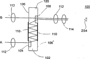
さて、図15から図17は、下記に光学系100として言及する本発明による光学系の二つのオプション的な実施例を示すものである。光学系100は、観察者が第一の光景Aと第二の光景Bとを同時に見るために用いるものである。
光学系100は、少なくとも一つの(図15及び図17aから17cにおいては一つ、図16においては二つの)入力ホログラフィック光学素子104を含むホログラフィックプレート102から構成される。したがって、図15及び図17aから17cにおいては、入力ホログラフィック光学素子104は、光景Aからの入射光をホログラフィックプレート102に入れるためのものである。この場合、光景Bからの光は、プレート102の外面106にほぼ直角に当たるため、直接的にホログラフィックプレート102に入る。他方、図16においては、入力ホログラフィック光学素子104は、両光景A及びBからの入射光をホログラフィックプレート102に入れるためのものである。
本技術分野で良く知られるように、ホログラフィックプレートは、光透過材から作られた本体120を含んで形成され、この本体120には第一側106と第二側106’とがある。好適実施例においては、入力ホログラフィック光学素子104は本体120の第一側106に形成される。本体120が形成される材料、そして入力ホログラフィック光学素子の各々は、本体120に入る任意の方向を持つ入射光が回折されてほぼ完全な内反射を生じるように選択する。
しかしながら、これらの場合(図15及び図17aから17c、そして図16)、ホログラフィックプレート102は、さらに少なくとも一つの出力ホログラフィック光学素子108を含む。出力ホログラフィック光学素子108は、ホログラフィックプレート102に入った光を、ホログラフィックプレート102から出して観察者の眼254に到達させるためのものである。ホログラフィックプレート102の光を受けない箇所は、図15に示すように、不透明なカバー110で覆われている。出力ホログラフィック光学素子は本体120の第二側106’に形成されるため、どの出力ホログラフィック光学素子に到達する光も、入射光の任意の方向とほぼ同じ方向へ本体120から出て、例えば図15から図17に示すように、観察者の眼254に到達する。ここに用いる「ほぼ同じ方向」は、プレート102の一方の側106を介して入り、他方の側106’を介して出ることを意味する。
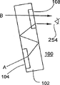
ホログラフィックプレート102が観察者の眼254に対して配置され、入力及び出力ホログラフィック光学素子が本体120に対して配置されるため、第一及び第二の光景A及びBの両方からの光は、観察者の眼254に同時に導かれる。図17aから17cに示すように、(i)これらの光景からの光は、種々の方向から光学系100に到達するかもしれないが、それでも光学系100は観察者の眼254の中へ光を同時に導くのに適している。(ii)光学系100、そして特にプレート102は、観察者の眼254に対して種々の向きで配置されてもよい。そして(iii)図17cに示すように、プレート102を一つ以上の領域において曲げることによって、両光景A及びBからの光がプレート102に同時に入ることが可能な状態の角度を広げることができる。この場合、この曲線によって、プレート102のほぼ完全な内反射の特性に悪影響を与えないようにすべきである。
平面光学、そして特にホログラフィック要素を形成する手段に関する詳細については、例えば、フリーゼム氏及びアミタイ氏による「光学の傾向」及びジュルゲン・ジョンズ氏及びスーザン・J・ウォーカー氏による「薄膜付着によって製造された回折マイクロレンズの二次元アレイ」に述べられている(A. A. Friesem and Y. Amitai(1996)in”Trends In Optics”. A Consortini, Ed. Academic Press, NY, pp. 125-144; Jurgen Johns and Susan J. Walker(1990)Two-dimensional array of diffractive microlenses fabricated by thin film deposition, Applied Optics 29:9231-9236)。
本発明の好適実施例においては、光学系100は、上記の光学系250のように、同様の理由により、照準レンズ112を含む。例えば、一対の照準レンズ112を、光景A及びBの各々とプレート102との間に配置してもよい。択一的に、単一の照準レンズ112を、プレート102と観察者の眼254との間に配置してもよい。
また、上記の光学系250と同様に、光学系100も、さらに矯正光学レンズ114を含んでもよい。択一的に、光学系250に対して、すべて上記に詳しく述べたように、視覚異常のある人が用いる眼鏡に取り付けが可能なように、光学系100を調整してもよい。光学系250の他の特徴、例えば、ヘッド・アレンジメント、ハウジング等も光学系100に含めてもよい。さらに、二つの光学系100を含むヘッド・セットも本発明の範囲内にある。この場合、各光学系100は、観察者の一つの眼の前に近づけて配置される。したがって、光学系100は、一対の関連する光景を同時に見るのに適当であり、そのように用いることが好ましい。この用語「関連する光景」は、光学系250に対して上記に定義している。光学系250に関しては、観察者が、第一の光景Aを一方の眼で、そして第二の光景Bを他方の眼で同時に見ることを可能にするために、ヘッド・セットを用いてもよい。この場合、ヘッド・セットは、観察者の一方の眼、例えば眼254の前に配置した、単一の光学系100を含む。これは、ほぼ第一の光景Aからの光だけを眼254に到達させると共に、同時に、眼254が、観察者の他方の眼と同様に、第二の光景Bに向けられていても、第二の光景Bからの光が眼254に到達しないように遮るためのものである。
現在、非常に高い屈折率を持つ光透過材が既知であるため、眼鏡や他の光学装置に用いるレンズの厚さは減少し、また、湾曲も平らになって来ている。そのような小さな湾曲のレンズは、本発明による矯正光学レンズとして用いるのに非常に適している。それらの内面に、僅かに湾曲したホログラフィックプレートを接着して矯正光学レンズを形成することができる。先に説明した遮光メカニズムをも、一つの光景、例えばAからの光が観察者の一方の眼、例えば眼254に到達しないように、また他の光景、例えばBからの光が観察者の他方の眼に到達しないよう遮って、観察者の各々眼に異なる光景を見させる目的で、光学系100に用いてもよい。
本発明は、限られた実施例で説明したが、多くの変更及び改良、そして他の用途が可能であることは明らかである。 Field and background of the invention
The present invention relates to an optical system for directing light from two scenes to an observer's eye, alternatively or simultaneously, and in particular, alternatively, directing light from two scenes to an observer's eye. , Or at the same time, to an optical system that uses a planar optical approach. Therefore, the optical system according to the present invention does not require the cumbersome operation of having to position the head and eyes with respect to the scene to be observed, which is necessary when using conventional bifocal glasses. Bifocal glasses can be provided. Furthermore, the present invention relates to an optical system that simultaneously guides light from two scenes to one or both eyes of an observer using a geometrical or planar optical approach. Therefore, the optical system according to the present invention does not use active light for display.
The term “scene” as used in this specification and claims refers to an object or set of objects that is perceived by an observer through passive light, ie through light from outside the optical system of the present invention.
Passive light can be, for example, light reflected or scattered by an object or set of objects, or emitted light from an object or set of objects. In other words, the passive light is light from the outside of the optical system of the present invention that can be recognized by an observer even when the optical system of the present invention does not exist.
In contrast, the term “active light” as used herein is intended to include light generated from components of the subject optical system. Thus, for example, since a conventional head-up display (HUD) system includes a cathode ray tube (CRT), the light generated by the CRT is active light. The view by active light defined here is defined here as a display. The term “scene” referred to herein specifically excludes displays formed by active light, such as those used in HUD systems, for example, and the term “image” as used herein refers to both scenes and displays. means. A real image shows a scene and a virtual image shows a display.
Since the optical system of the present invention does not include a light source, all light recognized by an observer using the optical system of the present invention is passive light. It should be noted that, as defined herein, within the scope of the present invention, for example, even a television screen or even a computer monitor, either a television screen or a computer monitor, Since it is not part of the optical system, it is considered to be passive light.
People who need glasses because of various visual abnormalities account for a high percentage of the population.
Conventional eyeglasses typically consist of a frame that supports the eyeglasses in an appropriate position in front of the eyes, and two lenses housed in the frame, one for each eye. , With focus characteristics to correct specific visual abnormalities of the eye.
Thus, for example, in the case of myopia, this is a visual anomaly related to the focus that results from too much force on the eye lens and cornea and / or that the eyeball is too long, but the positive focusing power is too strong Therefore, the image of a distant object is focused in front of the retina and cannot be clearly focused. For this reason, a diverging lens is selected so that an image is formed at the farthest point where the myopic eye can focus.
On the other hand, in the case of hyperopia, this is the opposite of myopia and results from the ability of the eye's refractive elements to be too little and / or the eyeball too short, but images of distant objects (when the eye is relaxed) ) Behind the retina. Therefore, hyperopia is corrected by the converging lens.
Myopia and hyperopia are visual abnormalities when looking at distant objects. On the other hand, presbyopia is one of the visual anomalies associated with seeing nearby objects, and often impairs reading ability. Presbyopia usually results from the hardening of the material that forms the lens over the course of age, which reduces the ability of the eye to focus on (adapt to) nearby objects. Therefore, presbyopia is corrected by a converging lens so that it can be read comfortably.
However, in many cases, a single eye has a long-distance visual abnormality such as myopia or hypermyopia that limits the visual ability of the scenery, and a short-distance visual abnormality such as presbyopia that restricts the ability to read.
Thus, a person who has a double abnormality in the eye is composed of a first set that provides a correction optical element for a long-distance visual abnormality and a second set that provides a correction optical element for a short-distance visual abnormality. A set of glasses, or alternatively known as bifocal glasses in the art, from a combination of two lenses, each having an arbitrary (different) focal length and optical properties, arranged adjacent to each other A set including a bifocal lens is required. Multifocal eyeglasses are known but are not used much because they are expensive and many people cannot adapt well.
However, these solutions have disadvantages. If you use one pair for reading, one for viewing a distance, or two pairs of glasses, you must always change your glasses when you move from near to far away or from far away to nearby objects. is there. When using bifocal glasses or multifocal glasses, different lines of sight are forced to look closer and far away, and in both cases the field of view is limited. Usually, for reading, it is necessary to lower the eyes while turning the head almost straight forward. If an object is placed in a position close to the person, in order to clearly see the object, the person must lower his eyes while tilting his head back. . Many people do not use bifocal glasses because of problems with the head and neck.
Accordingly, there is a widespread need for an optical system to direct light from two scenes to an observer's eye alternatively or simultaneously, and it is very advantageous to obtain such. Such an optical system can provide bifocal or multifocal glasses that do not require the head and eyes to be positioned relative to the scene being viewed.
There are endless situations in which people want to see sights in relatively different positions on a daily basis. For example, without limitation, (i) taking notes while looking at a blackboard, instructor or display (eg, slide screen). In this case, the observer is usually interested in seeing both his notes on the table or writing board and the blackboard, lecturer or display. (Ii) Draw a picture while watching the drawing object (for example, landscape). In this case, the observer is interested in seeing both his drawing board and the drawing object. (Iii) Type on the keyboard while looking at the screen. In this case, the in-pro typist is interested in seeing both the keyboard and the screen. (Iv) While looking at or reading a printed material (for example, a map, a guide, a book, etc.), another sight (for example, a road, a device, etc.) is viewed. In this case, the observer is interested in seeing both the printed material and other scenes.
However, in the above and similar situations, the field of view that the observer can focus on is relatively narrow, so at a point in time, the observer sees only one scene. This creates a disadvantage. (I) When an observer is looking at one scene, he cannot notice a change in the other scene. Thus, for example, when a driver or pilot is looking at a road map or navigation map, he or she cannot see the road or sky ahead. And (ii) the observer finds it difficult to compare between scenes. Therefore, it is difficult for a painter to compare his drawing with the object to be drawn, for a typist, it is difficult to detect a typo, and for a student, from a blackboard or display to his notes etc. It is difficult to copy the contents.
Therefore, the need for an optical system that simultaneously guides light from two scenes to the viewer's eyes is widely recognized and it is very advantageous to obtain such.
Summary of invention
In accordance with the present invention, an optical system is provided for directing light from at least two scenes to an observer's eye alternatively or simultaneously. In addition, an optical system is provided for directing light from the two scenes simultaneously to one or both eyes of the observer. This can be used to allow an observer to view the first scene and the second scene at the same time. The optical system according to the present invention uses only passive light from the scene and does not use active light as opposed to a head-up display (HUD) system.
Further according to the features of the preferred embodiments described below, the optical system according to the present invention comprises: (A) A first lens having a first focal length. (B) A second lens having a second focal length. Since the first and second lenses are placed adjacent to each other in front of one eye of the observer, a single ray from either scene can only be routed through one of the first and second lenses. pass. And (c) directing the incident light that has passed through the first lens from the first scene into the observer's eye, and at the same time, incident light that has passed through the second lens from the second scene to the observer's eye Optical device for guiding into the eye. This optical device is disposed between the first and second lenses and the eyes of the observer.
According to another embodiment of the invention, the optical system consists of: (A) A magnifying eyepiece with a short focal length to magnify a nearby scene and to correct the aim of light passing therethrough. (B) An optical device for guiding incident light that has passed through a magnifying sighting lens from a near scene into the observer's eye and simultaneously guides incident light from a distant scene into the observer's eye. And (c) a correction eyepiece for correcting long-distance visual anomalies. This correction lens is placed between the optical device and the eyes of the observer.
Further in accordance with features in the preferred embodiments the optical device includes a holographic plate.
Further in accordance with features in the preferred embodiments the holographic plate includes at least one holographic optical element.
Further in accordance with features in the preferred embodiments, the holographic plate includes a first input holographic optical element for entering incident light that has passed through the first lens into the holographic plate.
Further in accordance with features in the preferred embodiments, the holographic plate includes a first input holographic optical element for placing incident light that has passed through the magnification aiming lens into the holographic plate.
Further in accordance with features in the preferred embodiments, the holographic plate further includes a second input holographic optical element for placing incident light that has passed through the second lens into the holographic plate.
Further in accordance with features in the preferred embodiments, the holographic plate further includes a second input holographic optical element for entering incident light from a distant scene into the holographic plate.
Further in accordance with features in the preferred embodiments, the holographic plate further includes an output holographic optical element for causing light entering the holographic plate to exit the holographic plate and reach the viewer's eyes.
Further according to the features in the preferred embodiments, the optical device includes at least one reflective optical element.
Further according to the features in the preferred embodiments, the optical system further includes: (d) blocking light from one of the first and second scenes from reaching the observer's eye for at least any time. The light shielding mechanism.
Further, according to features in the preferred embodiments, the optical system further comprises (d) blocking light from one of the near and far sights from reaching the viewer's eyes at least for any time. Consists of light shielding mechanism.
According to another embodiment of the present invention, there is provided glasses comprising two optical systems according to any of the above embodiments.
According to another embodiment of the present invention, there is provided a headset for three-dimensional visual recognition comprising two optical systems including a light blocking mechanism.
According to another embodiment of the present invention, an optical system is provided that can be used by an observer to obtain three-dimensional visual recognition of a scene presented by a first image and a second image. In this case, each of the first and second images includes spectacle disparity information. The optical system comprises a first holographic plate and a second holographic plate, each of the first and second holographic plates including: (a) having a first side and a second side. A body formed from a light transmissive material. (B) At least one input holographic optical element formed on the first side of the body. Note that the material and each of the input holographic optical elements are selected so that incident light having an arbitrary direction entering the body is diffracted to cause almost complete internal reflection. And (c) at least one output holographic optical element formed on the second side of the body. For this reason, light reaching any output holographic optical element exits the body in a direction similar to any direction of incident light. In this case, the first holographic plate is intended to allow only light from the first image to reach one eye of the observer, and the second holographic plate is approximately from the second image. Is intended to reach only the other light of the observer.
Further in accordance with features in the preferred embodiments, each holographic optical element further includes a light blocking mechanism for blocking light.
Furthermore, according to features in preferred embodiments of the invention described below, a method is provided for allowing an observer to view a first scene and a second scene. This method consists of the following steps. (A) providing a viewer with a first eyepiece having a first focal length; (B) providing a viewer with a second eyepiece having a second focal length; The first and second lenses are placed adjacent to each other in front of one eye of the observer so that a single ray from any scene can only pass through one of the first and second lenses To do. And (c) directing the incident light that has passed through the first lens from the first scene into the observer's eye, and at the same time, incident light that has passed through the second lens from the second scene to the observer's eye Providing an observer with an optical device for directing into the eye. The optical device is disposed between the first and second lenses and the observer's eye.
Furthermore, the features in the preferred embodiment of the invention described below provide a method that an observer can use to view near and far sights. This method consists of the following steps. (A) Providing an observer with a magnifying aim eyepiece with a short focal length to magnify a nearby scene and to correct the aim of the light passing therethrough. (B) an optical device for directing incident light from a near scene that has passed through a magnifying aiming lens into the observer's eye and simultaneously guiding incident light from a distant scene into the same eye of the observer; Step to provide to the observer. And (c) providing a viewer with a correction eyepiece for correcting a long-distance visual abnormality. This correction lens is placed between the optical device and the same eye of the observer.
In addition, according to features in preferred embodiments of the present invention described below, an optical system is provided for allowing an observer to view a first scene and a second scene simultaneously. In this case, both the first and second scenes are visible to the observer via passive light, and this optical system consists of: (A) A head arrangement for placing the optical system on the observer's head and placing the optical system in front of the observer's eyes. And (b) a beam splitter arranged so that both light from the first scene and light from the second scene are simultaneously guided into the observer's eyes.
Further, according to features in the preferred embodiment, the first scene is a near scene and the second scene is a distant scene, so that light from a distant scene is naturally nearly aimed. In this case, the optical system further comprises (c) an aiming lens for correcting the aim of light from a near scene, and this aiming lens is supported by a head arrangement.
Further, according to a feature in the preferred embodiment, since both the first and second scenes are nearby scenes, the light from either scene is unfocused light. In this case, the optical system is further supported by (c) a first aiming lens for correcting the aim of the light from the first scene, which is supported by the head arrangement, and (d) by the head arrangement. And a second aiming lens for correcting the aim of the light from the second scene.
Further according to the features in the preferred embodiments, the optical system further comprises (c) at least one reflector supported by the head arrangement, wherein the at least one reflector reflects the light from the first scene. For guiding to the beam splitter.
Further, according to the features in the preferred embodiment, the optical system further comprises (c) a correcting optical lens for correcting an observer's visual abnormality, the correcting optical lens comprising a beam splitter and an observer's eye. And is supported by a head arrangement.
Furthermore, according to the features in the preferred embodiments of the invention described below, a method is provided for allowing an observer to view a first scene and a second scene simultaneously. In this case, both the first and second scenes are visible to the observer via passive light, and this method includes (a) light from the first scene and light from the second scene. Providing the viewer with a beam splitter that is arranged to simultaneously guide both to the viewer's eyes.
Further, according to features in the preferred embodiment, the first scene is a near scene and the second scene is a distant scene, so that light from a distant scene is naturally nearly aimed. In this case, the method further comprises (b) providing the observer with an aiming lens to correct the aiming of light from a nearby scene.
Further, according to a feature in the preferred embodiment, since both the first and second scenes are nearby scenes, the light from either scene is unfocused light. In this case, the method further comprises the following steps. (B) providing a viewer with a first aiming lens to correct the aim of light from the first scene; And (c) providing the observer with a second aiming lens to correct the aim of the light from the second scene.
Further according to the features in the preferred embodiments, the method further comprises the step of: (b) providing at least one reflector to the viewer, the at least one reflector receiving light from the first scene. For guiding to a beam splitter.
Further according to the features in the preferred embodiments, the method further comprises the step of: (b) providing the observer with a corrective optical lens for correcting the observer's visual anomalies, the corrective optical lens comprising a beam splitter and It is arranged between the eyes of the observer.
Further in accordance with features in the preferred embodiments, the beam splitter allows the viewer to adjust the optics so that the first and second scenes are visible when the viewer moves his head and the viewer. Is movable with respect to the head arrangement so that it can select another pair of views to watch at the same time.
Further, according to a feature in the preferred embodiment, since both the first and second scenes are distant scenes, the light from both scenes is naturally nearly aimed.
Further, according to features in the preferred embodiments, at least one of the at least one reflector and beam splitter is optical for the viewer to view the first and second scenes when the viewer moves his head. It is movable relative to the head arrangement so that the system can be adjusted and the viewer can select at least one replacement scene to watch simultaneously with the second scene.
Further in accordance with features in the preferred embodiments, the beam splitter and the reflector are each formed as a first surface and a second surface of a single optical element having a volume.
Further in accordance with features in the preferred embodiments, the reflector is an aiming reflector and the beam splitter is an aiming beam splitter. For this reason, the light from the first scene is aimed by the aiming reflector before reaching the beam splitter.
Further, according to features in the preferred embodiments, the beam splitter and the at least one reflector are relative to the first scene and the viewer's eye so that the first scene is visible at a steep angle. Be placed.
Further, according to a feature in the preferred embodiment, since the beam splitter is an aiming beam splitter, light from the first scene is aimed by the aiming beam splitter before reaching the observer's eye. The
Furthermore, according to the features in the preferred embodiments of the present invention described below, in order to allow the observer to view the first scene and the second scene at the same time, comprising the two optical systems described above. A headset is provided. In this case, each of the two optical systems is disposed in front of one eye of the observer.
Furthermore, according to the features in the preferred embodiments of the present invention described below, in order to allow the observer to simultaneously view the first scene with one eye and the second scene with the other eye. A headset is provided. This head set is composed of the optical system described above, and the optical system is disposed in front of one eye of the observer. In this case, since the beam splitter functions almost only as a reflecting surface, the first eye of the observer faces the second scene, and at the same time, the other eye of the observer faces the second scene. Light from one scene is directed to one eye of the observer.
In addition, according to features in preferred embodiments of the present invention described below, an optical system is provided for allowing an observer to view a first scene and a second scene simultaneously. In this case, both the first and second scenes are visually recognized by the observer via passive light, and this optical system is composed of a holographic plate. The holographic plate includes: (A) A body formed from a light transmissive material having a first side and a second side. (B) At least one input holographic optical element formed on the first side of the body. It should be noted that each of the material and at least one input holographic optical element is selected so that incident light having any direction entering the body is diffracted to cause almost complete internal reflection. And (c) at least one output holographic optical element formed on the second side of the body. For this reason, light reaching any of the at least one output holographic optical element exits the body (enters from one side of the plate and exits from the other) in a direction similar to any direction of incident light. Reach the eyes. In this case, the holographic plate is arranged with respect to the observer's eye and at least one input and output holographic optical element is arranged with respect to the body. Thus, light from both the first and second scenes is simultaneously guided into the viewer's eyes.
Further in accordance with features in the preferred embodiments, the body is curved in at least one location.
Further, according to features in the preferred embodiment, the first scene is a near scene and the second scene is a distant scene, so that light from a distant scene is naturally nearly aimed. In this case, the optical system further includes (d) an aiming lens for correcting the aim of light from a nearby scene.
Further, according to a feature in the preferred embodiment, since both the first and second scenes are distant scenes, the light from both scenes is naturally nearly aimed.
Further, according to a feature in the preferred embodiment, since both the first and second scenes are nearby scenes, the light from either scene is unfocused light. In this case, the optical system further comprises: (D) A first aiming lens for correcting the aim of light from the first scene. The first aiming lens is disposed between the first scene and the holographic plate. And (e) a second aiming lens for correcting the aim of light from the second scene. The second aiming lens is disposed between the second scene and the holographic plate.
Further, according to features in the preferred embodiments, the optical system further comprises (d) a holographic plate and an observer's eye for aiming light from both the first and second scenes. It consists of an aiming lens arranged between them.
According to still further features in the described preferred embodiments the optical system further comprises: (d) a correcting optical lens for correcting an observer's visual anomaly, the correcting optical lens comprising a holographic plate and an observer's eye. Between. Furthermore, according to the features in the preferred embodiments of the present invention described below, in order to allow the observer to view the first scene and the second scene at the same time, comprising the two optical systems described above. A headset is provided. In this case, each of the two optical systems is disposed in front of one eye of the observer.
Furthermore, according to the features in the preferred embodiments of the present invention described below, in order to allow the observer to simultaneously view the first scene with one eye and the second scene with the other eye. A headset is provided. This head set is composed of the above-described optical system, and the optical system is disposed in front of one eye of the observer. When one eye of the observer is facing the second scene and at the same time the other eye of the observer is also facing the second scene, the optical system allows light from the first scene to be transmitted to one eye of the observer. At the same time, blocking light from the second scene from reaching one eye.
Further in accordance with features in the preferred embodiments, the first and second scenes form a pair of related scenes. This pair of related scenes consists of notebook and blackboard, notebook and lecturer, notebook and screen, picture and drawing object, keyboard and screen, print and screen, print and road ahead, and print and sky in front. Selected from a group of pairs.
Further in accordance with features in the preferred embodiments, a method is provided for enabling an observer to view a first scene and a second scene simultaneously. In this case, both the first and second scenes are visually recognized by the observer via passive light, and the method comprises the following steps. (A) providing a viewer with a holographic plate; The observer sees the scene through this holographic plate. The holographic plate includes the following. (I) A body formed from a light transmissive material having a first side and a second side. (Ii) At least one input holographic optical element formed on the first side of the body. The material, and each of the at least one input holographic optical element, is selected such that incident light with any direction that enters the body via the at least one input holographic optical element causes almost complete internal reflection. . And (iii) at least one output holographic optical element formed on the second side of the body. For this reason, light reaching any of the at least one output holographic optical element exits the main body in a direction substantially similar to an arbitrary direction of incident light and reaches one of the eyes of the observer. And (b) positioning the holographic plate relative to the observer's eye and at least one input and output holographic optical element relative to the body. This allows passive light from both the first and second scenes to be simultaneously directed to the viewer's eyes.
The present invention solves the deficiencies of currently known instrument configurations by providing an optical system that directs light from two scenes alternatively or simultaneously to the viewer's eyes. Therefore, the optical system of the present invention does not need to change the position of the observer's head or the direction of the eye, which is necessary for bifocal glasses when changing from far vision to short vision, It can be used easily and comfortably instead of bifocal glasses. (Ii) It can also be used for 3D visual recognition. (Iii) It is also possible to bring visual information outside the viewer's field of view into the field of view without the viewer changing the position of the head and / or the direction of the eyes. Furthermore, the present invention solves the deficiencies of currently known instrument configurations by providing an optical system that simultaneously guides passive light from two scenes to the viewer's eyes. This optical system can be used to allow an observer to view a pair of related scenes simultaneously.
Other features, objects and advantages of the optical system according to the present invention are described in the following section.
[Brief description of the drawings]
The invention will now be described, by way of example only, with reference to the following accompanying drawings.
FIG. 1 is a cross-sectional view of a conventional holographic plate.
FIG. 2 is a cross-sectional view of another prior art holographic plate used in various embodiments in accordance with the present invention.
3a to 3c are cross-sectional views showing three embodiments of the optical system according to the present invention.
FIGS. 4a to 4c are cross-sectional views showing three operating modes of the optical system of FIG. 3a equipped with a light blocking mechanism according to the present invention.
FIG. 5 is a cross-sectional view of the optical system shown in FIG. 3b with a second type of light shielding mechanism type according to the present invention.
6a and 6b are cross-sectional views showing two modes of operation of the optical system for three-dimensional vision according to the present invention.
FIGS. 7a and 7b are cross-sectional views showing two configurations of optical systems that allow viewing near and / or distant views simultaneously or alternatively in accordance with the present invention.
FIG. 8 is a front view of glasses, a headset, that is, an optical system for three-dimensional vision according to the present invention.
9 to 11 are sectional views of three head-up display (HUD) systems according to the prior art.
12 and 13 are cross-sectional views showing two embodiments of an optical system using the principle of geometric optics according to the present invention.
Figures 14a to 14c show three alternative configurations of beam splitters and reflectors in the optical system of the present invention that allow an observer to see the first scene at a steep angle and natural orientation. FIG.
15 and 16 are cross-sectional views showing two embodiments of an optical system using the principle of planar optics according to the present invention.
17a to 17c are cross-sectional views showing three optional configurations of the optical system of FIG.
DESCRIPTION OF PREFERRED EMBODIMENTS
The present invention relates to an optical system for alternatively or simultaneously directing light from at least two scenes to the viewer's eyes, providing the viewer with images of two or more scenes at different or single times. Can be used to In particular, the present invention can be used to provide bifocal glasses that do not require inconvenient positioning of the head and eyes with respect to the scene to be viewed. According to another embodiment, the present invention relates to an optical system for simultaneously directing light from two scenes to one or both eyes of the viewer, where the viewer views a pair of related scenes simultaneously. It makes it possible. In particular, this embodiment of the invention allows an observer to notice changes in one or both scenes simultaneously and accurately compare one of the scenes to the other.
In order to better understand the first embodiment of the present invention shown in FIGS. 3 to 8, first, the construction and operation of the conventional (ie, prior art) holographic plate shown in FIGS. 1 and 2 will be described. .
Reference is now made to the drawings. FIG. 1 shows a conventional holographic plate. This is referred to as
However, the prior art
As will be described in more detail below, the prior art configuration shown in FIG. 1 in which both the scene and the viewer are positioned in the same direction relative to the holographic plate is often the various embodiments according to the present invention. It is a limitation.
Reference is now made to FIG. This is another prior art
Thus, like the
In this specification, and particularly in the claims section below, when the phrase "almost complete internal reflection" is used, it means that in some cases, some of the light is not reflected due to impurities, poor polishing, etc. Total reflection including the limit of leaking from the plate. These phenomena are well known in the art. In fact, true total internal reflection (ie, 100% reflection of light) is theoretical. However, up to a few percent loss of light (eg, less than 10%, preferably less than 5%, more preferably less than 1%, most preferably less than 0.1%) Are acceptable and are included within the definition of “almost complete internal reflection” as used herein. Further, as is known in the art, the amount of internal reflection (eg, at different locations) is electrically controllable, and such electrically controlled holographic plates are also used herein. Included within the definition of “holographic plate”.
However, in contrast to the
Although the
Therefore, in a broad sense, the
Other examples of holographic plates are described in “Optical Trends” by Friezem and Amitai (AA Friesem and Y. Amitai (1996) in “Trends In Optics”. A Consortini, Ed. Academic Press. , NY, pp. 125-144). In particular, various examples of holographic plates represented in the references cited above are included herein by reference.
Reference is now made to FIGS. 3a to 3c. These are three alternative embodiments of the optical system according to the invention, referred to below as
The term “scene” as used in this specification, and particularly in the claims below, refers to a scene that is visible to the naked eye, eg, moving and non-moving objects, displays, images, etc. Furthermore, the two scenes, such as A and B, used here represent both two independent scenes, overlapping scenes, and also include two single scenes observed at slightly different angles. Thus, when the phrase “at least two scenes” is used, this refers to at least two scenes, as the term “scene” is defined above.
The
In FIGS. 3a to 3c and subsequent figures,
In addition, for many applications, the focal lengths of
The
As will be described below, each of FIGS. 3a-3c shows a somewhat different configuration of
The holographic plate 54 includes at least one input holographic optical element 56 (one in FIG. 3a and two in FIG. 3b). Thus, in FIG. 3a, incident light that passes through the
In the drawings, the lines of sight from different scenes are shown in parallel, but there is no intention to limit the scope of the invention to only parallel lines of sight, and the invention is not limited to being parallel or non-parallel. It can also be applied to two scenes or lines of sight.
However, in these cases, the holographic plate 54 further includes at least one output holographic
As shown in FIG. 3c, the
Currently, for example, the fabrication and operation of planar optical elements demonstrated in FIGS. 3a and 3b are much less limited when compared to non-planar (ie geometric) optical elements demonstrated in FIG. Embodiments utilizing planar optics are preferred. For more information on planar optics, especially the means of forming holographic elements, see, for example, “Optical Trends” by Friezem and Amitai and “Diffraction microfabricated by thin film deposition” by Jurgen Johns and Susan J. Walker. AA Friesem and Y. Amitai (1996) in “Trends In Optics”. A Consortini, Ed. Academic Press, NY, pp. 125-144; Jurgen Johns and Susan J. Walker (1990) Two-dimensional array of diffractive microlenses fabricated by thin film deposition, Applied Optics 29: 931-936).
In the preferred embodiment of the present invention, the
In this case, each of the
Currently, light transmissive materials with very high refractive indices are known, so that the thickness of lenses used in eyeglasses and other optical devices is reduced and their curvature is flattened. Such a small curved lens is very suitable for use in the glasses according to the invention, since a slightly curved holographic plate can be glued to the inner surface (facing the eye).
Similarly, two or more lenses can be used in the
Reference is made to FIGS. 4a to 4c. According to a preferred embodiment of the present invention, the
In the first operating mode shown in FIG. 4b, the
In the second mode of operation shown in FIG. 4c, the
In the third mode of operation shown in FIG. 4 a, the
Therefore, in the first operation mode shown in FIG. 4b, only the scene B appears in the observer's
This embodiment of the optical system according to the invention is suitable, for example, for an observer who cannot ignore out-of-focus scenes as explained above. Such an observer can select and view the scene by simply moving the
As will be apparent to those skilled in the art, (i) the
In FIG. 5, the configuration of the
In another preferred embodiment of the present invention shown in FIG. 8, the
For this reason, two optical systems 40 (preferably using one of the configurations shown in FIGS. 3a and 3b) are mounted in a suitable frame, for example a conventional head set frame (not shown), and the
In fact, for the purpose of three-dimensional vision, the
Therefore, in the first operation mode shown in FIG. 6a, only the image B is visible to the observer's
If the images A and B are arranged in a predetermined manner for the viewer, i.e. the left image (i.e. the image at the left angle with respect to the scene), e.g. the image A is the left eye of the viewer, this In such a way that the right image (ie, the image at the right angle to the scene), eg image B, is visible to the viewer's right eye, in this case the
Therefore, according to the present invention, there is provided an optical system that allows an observer to view a scene as three-dimensional. In this case, the scene is presented as a first image and a second image, and each of the first and second images includes disparity information of the scene. The optical system comprises first and second holographic plates each having a body formed of a light transmissive material, each further comprising at least one input holographic formed on the first side of the body. Including optical elements. Each of the material forming the body and the input holographic optical element diffracts incident light with any direction entering the body, resulting in almost complete internal reflection, as defined above for the term “internal reflection”. To choose. Each of the first and second plates further includes at least one output holographic optical element formed on the second side of the body so that light reaching the output holographic optical element can be transmitted from the body to the incident light. Exit in almost the same direction as any direction. The optical system ensures that only the light from the first image reaches one eye of the observer by the first holographic plate, and only the light from the second image by the second holographic plate. It is formed so as to reach the other eye of the observer. In order to make this possible, each of the holographic plates preferably further comprises a light shielding mechanism.
In another embodiment of the present invention, the
Reference is now made to FIGS. 7a and 7b. According to another preferred embodiment of the present invention, there is provided an optical system, described below as
Figures 7a and 7b show two optional embodiments of an
The
The holographic plate 54 includes at least one input holographic optical element 56 (one in FIG. 7a and two in FIG. 7b). Accordingly, the input holographic
In either case, however, the holographic plate 54 further includes at least one output holographic
The
According to the configuration of the
The optical system according to the second embodiment of the present invention uses passive light from a scene and uses active light (ie, a display) as part of the system as opposed to a head-up display (HUD) system. There is nothing.
For a better understanding of the second embodiment of the present invention shown in FIGS. 12 through 17 of the drawings, now a conventional (ie, prior art) head-up display (HUD) as shown in FIGS. ) Describe system configuration and operation.
A conventional HUD system, referred to below as
The
As shown in FIG. 9, the
As shown in FIG. 10, the
As shown in FIG. 11, the
In some cases, all of the optical elements described above for
Some prior art HUD systems are stationary, but others are (at least partially) attached to headsets, helmets, etc. so that the system is always in front of the viewer's eyes. However, all prior art HUD systems are limited to simultaneous presentation of one scene visually perceived via passive light and one display visually perceived via active light ( The terms “passive light” and “active light” are defined in the background section above). None of the currently known HUD systems aim at the simultaneous vision of two scenes in the meaning defined above, which is the basis of the present invention. In other words, in the HUD system, each eye of the observer has one real image formed by passive light reaching the observer's eye and one virtual image formed by active light reaching the observer's eye. Are simultaneously recognized visually. In many cases, the light from both images is either natural or optical so that both images are clearly visible when the observer's eyes are fairly relaxed (ie, not adapted for short distance vision). , Almost or completely aiming.
The principle and operation of the optical system according to the present invention can be better understood from the following drawings and description thereof.
12 and 13 show several embodiments of the optical system according to the present invention, which will be referred to as
The
As will be apparent to those skilled in the art, if the components of the
Even in the configuration with the least number of components, the
In the preferred embodiment, the
In many cases, the first scene A (or A ') is a near scene and the second scene B is a distant scene. As used herein, the term “near view” refers to a view located within a certain distance from the viewer when the eye needs to focus (adapt) to view the near view. Thus, nearby scenes are usually located within a range of several centimeters to several meters from the viewer. As used herein, the term “far view” refers to a view that is located within a certain distance from the viewer so that the viewer hardly needs to focus (adapt) the eye to see the far view. . Thus, distant scenes are usually located in the range of, for example, 5 to 10 meters, or such as from 100 to 1000 meters, or even further from the viewer. If the first scene A (or a ′) is a near scene and the second scene B is a far scene, the light from the far scene B will be almost naturally (because it arrives from far away). The aim is correct, but light from a nearby scene A (or A ′) is not correct. This is a problem for the observer to see both scenes clearly and simultaneously. The reason is that the
However, if the scenes A (or A ') and B are both distant scenes, the light from both scenes A (or A') and B is naturally nearly aimed. In this case, it is not necessary to correct the aim, but it is preferable to perform aiming so that the
Further, if the first scene A (or A ') and the second scene B are both nearby scenes, the light from the scenes A (or A') and B will not be aimed. In this case, for some applications, the
Furthermore, it is preferable not to aim at all for other applications. For example, if an observer wants to receive light from two scenes at the same time and wants to focus clearly on only one scene, the scene will change even if the other scene is not in focus. Can attract the attention of the observer.
However, in the preferred embodiment, a position between the
Since the first scene A (or A ′) or the second scene B exists at an arbitrary position with respect to the observer, for example, the first scene may be positioned at A or A ′. Also, when the viewer views the first scene A after reflection from the
In many applications, the observer can adjust the
In another embodiment of the present invention,
The
For those who need glasses, the
As described above, the
If it is desirable for each of the observer's eyes to be able to see a different scene, the headset simply includes one
Exactly the same effect can be obtained by using the above-described headset using two
Reference is now made to FIGS. 14a and 14b. In HUD systems that include a reflector that directs light from a display (eg, a CRT display) to a beam splitter that functions as a combiner, the display may be displayed upside down or as a mirror image of a true display. . In a HUD system this is hardly a problem. Because the display itself can be changed (eg, displayed upside down or as a mirror image), an observer can view the display in a normal state (eg, a natural image with the right side on top).
However, this effect is a serious problem for an optical system used for viewing a scene by passive light. This is because the observer does not have control over the scene as when viewing the display.
For this reason, in the preferred embodiment of the present invention, the
In the configuration shown in FIGS. 14a to 14c, a reflecting
The
Further, refer to FIGS. 12 to 14. In accordance with the present invention, a method is provided for allowing an observer to view a first scene and a second scene simultaneously. In this case, both the first and second scenes are visible to the observer via passive light.
According to a preferred embodiment, the method includes the following steps. (A) Providing the viewer with a
According to a preferred embodiment, the method further includes providing the viewer with at least one
According to a preferred embodiment of the method of the present invention, the
According to another preferred embodiment of the method of the present invention, the method further comprises providing the viewer with a correcting
According to another preferred embodiment of the method of the present invention, the
The
FIGS. 15-17 illustrate two optional embodiments of the optical system according to the present invention, referred to below as
The
As is well known in the art, the holographic plate is formed including a
However, in these cases (FIGS. 15 and 17a to 17c, and FIG. 16), the
Because the
For details on planar optics, and in particular about the means of forming holographic elements, see, for example, “Optical Trends” by Friezem and Amitai and “Film produced by thin film deposition by Jurgen Johns and Susan J. Walker” A two-dimensional array of diffractive microlenses ”(AA Friesem and Y. Amitai (1996) in“ Trends In Optics ”. A Consortini, Ed. Academic Press, NY, pp. 125-144; Jurgen Johns and Susan J. Walker (1990) Two-dimensional array of diffractive microlenses fabricated by thin film deposition, Applied Optics 29: 9231-9236).
In a preferred embodiment of the present invention, the
Further, like the
Currently, light transmissive materials with very high refractive indices are known, so the thickness of lenses used in eyeglasses and other optical devices has decreased and the curvature has become flat. Such a small curved lens is very suitable for use as a correcting optical lens according to the present invention. A corrective optical lens can be formed by adhering a slightly curved holographic plate to the inner surface thereof. The shading mechanism described above also prevents the light from one scene, eg, A, from reaching one eye of the observer, eg,
Although the invention has been described with limited embodiments, it will be apparent that many variations and modifications and other uses are possible.
Claims (6)
(a)第一側及び第二側を持つ、光透過材から形成された本体と、
(b)前記本体の前記第一側に形成された少なくとも一つの入力ホログロフイック光学素子と、なお、前記材料、そして前記少なくとも一つの入力ホログラッフイック光学素子の各々は、少なくとも一つの入力ホログラッフイック光学素子を介して前記本体に入る任意の方向を持つ入射光がほぼ完全な内反射を起こすように選択されるものであり、そして
(c)前記本体に設けられた少なくとも一つの出力ホログラッフイック光学素子とを有し、このため、前記少なくとも一つの出力ホログラッフイック光学素子のいずれに到達する光も、前記入射光の前記任意の方向とほぼ同様な方向に前記本体から出て観察者の眼の一方に到達し、
この場合、前記ホログラッフイックプレートが前記観察者の前記の眼に対して配置され、前記少なくとも一つの入力及び出力ホログラッフイック光学素子が前記本体に対して配置されるため、前記第一及び前記第二の光景の両方からの受動光は、同時に前記観察者の前記眼の中に導かれるものであり、
遠くの光景からの光が自然にほぼ照準が正されるように、前記第一の光景は近くの光景であり、前記第二の光景は遠くの光景であり、
さらに前記光学系は、(d)前記近くの光景からの光の照準を正すための照準レンズを有する
ことを特徴とする光学系。Observer an optical system for enabling Rukoto viewed first and second sight simultaneously recognized visually by an observer both the first and second sight through the passive optical The optical system includes a holographic plate, and the holographic plate includes:
(A) a body having a first side and a second side, formed from a light transmissive material;
(B) at least one input holographic optical element formed on the first side of the body, each of the material, and each of the at least one input holographic optical element is at least one input holographic optical element. Fuikku a shall incident light is chosen to cause nearly complete internal reflection with any direction entering the body through the optical element, and (c) at least one output holo provided in the body and a Guraffuikku optical element, Therefore, light reaching any of said at least one output holo grabber off dichroic optical element also, out of the said body in substantially the same direction as the arbitrary direction of the incident light To reach one of the observer ’s eyes ,
In this case, since the holographic plate is disposed with respect to the eye of the observer and the at least one input and output holographic optical element is disposed with respect to the body, the first and passive light from both of the second scene is shall be simultaneously directed into the eye of the observer,
The first scene is a near scene, the second scene is a far scene, so that light from a distant scene is naturally aimed mostly.
The optical system further includes (d) an aiming lens for correcting the aim of light from the near scene .
Applications Claiming Priority (5)
| Application Number | Priority Date | Filing Date | Title |
|---|---|---|---|
| US08/746,526 US5724163A (en) | 1996-11-12 | 1996-11-12 | Optical system for alternative or simultaneous direction of light originating from two scenes to the eye of a viewer |
| US08/746,526 | 1996-11-12 | ||
| US75312696A | 1996-11-20 | 1996-11-20 | |
| US08/753,126 | 1996-11-20 | ||
| PCT/US1997/020234 WO1998021612A1 (en) | 1996-11-12 | 1997-11-10 | Optical system for alternative or simultaneous direction of light originating from two scenes to the eye of a viewer |
Publications (3)
| Publication Number | Publication Date |
|---|---|
| JP2001514764A JP2001514764A (en) | 2001-09-11 |
| JP2001514764A5 JP2001514764A5 (en) | 2005-07-14 |
| JP4155343B2 true JP4155343B2 (en) | 2008-09-24 |
Family
ID=27114618
Family Applications (1)
| Application Number | Title | Priority Date | Filing Date |
|---|---|---|---|
| JP52266698A Expired - Fee Related JP4155343B2 (en) | 1996-11-12 | 1997-11-10 | An optical system for guiding light from two scenes to the viewer's eye alternatively or simultaneously |
Country Status (8)
| Country | Link |
|---|---|
| US (1) | US6577411B1 (en) |
| EP (1) | EP0991965A4 (en) |
| JP (1) | JP4155343B2 (en) |
| AU (1) | AU730608B2 (en) |
| CA (1) | CA2270247C (en) |
| IL (1) | IL129515A (en) |
| NZ (1) | NZ335235A (en) |
| WO (1) | WO1998021612A1 (en) |
Families Citing this family (145)
| Publication number | Priority date | Publication date | Assignee | Title |
|---|---|---|---|---|
| JP2000089211A (en) * | 1998-09-11 | 2000-03-31 | Fuji Xerox Co Ltd | Image display device |
| KR100444981B1 (en) | 2000-12-15 | 2004-08-21 | 삼성전자주식회사 | Wearable display system |
| JP2004021078A (en) * | 2002-06-19 | 2004-01-22 | Nikon Corp | Combiner optical system and information display device |
| US6805490B2 (en) | 2002-09-30 | 2004-10-19 | Nokia Corporation | Method and system for beam expansion in a display device |
| US7205960B2 (en) | 2003-02-19 | 2007-04-17 | Mirage Innovations Ltd. | Chromatic planar optic display system |
| WO2004109349A2 (en) * | 2003-06-10 | 2004-12-16 | Elop Electro-Optics Industries Ltd. | Method and system for displaying an informative image against a background image |
| US7492512B2 (en) * | 2004-07-23 | 2009-02-17 | Mirage International Ltd. | Wide field-of-view binocular device, system and kit |
| JP4627040B2 (en) * | 2005-01-27 | 2011-02-09 | トヨタ自動車株式会社 | Zoom mechanism |
| US10073264B2 (en) * | 2007-08-03 | 2018-09-11 | Lumus Ltd. | Substrate-guide optical device |
| IL166799A (en) | 2005-02-10 | 2014-09-30 | Lumus Ltd | Substrate-guided optical device utilizing beam splitters |
| EP1932051A1 (en) * | 2005-09-14 | 2008-06-18 | Mirage Innovations Ltd. | Diffraction grating with a spatially varying duty-cycle |
| WO2007052265A2 (en) * | 2005-11-03 | 2007-05-10 | Mirage Innovations Ltd. | Binocular optical relay device |
| US10261321B2 (en) | 2005-11-08 | 2019-04-16 | Lumus Ltd. | Polarizing optical system |
| GB0522968D0 (en) | 2005-11-11 | 2005-12-21 | Popovich Milan M | Holographic illumination device |
| JP5226528B2 (en) | 2005-11-21 | 2013-07-03 | マイクロビジョン,インク. | Display having an image guiding substrate |
| JP2007219106A (en) * | 2006-02-16 | 2007-08-30 | Konica Minolta Holdings Inc | Optical device for expanding diameter of luminous flux, video display device and head mount display |
| GB0718706D0 (en) | 2007-09-25 | 2007-11-07 | Creative Physics Ltd | Method and apparatus for reducing laser speckle |
| US20100177388A1 (en) * | 2006-08-23 | 2010-07-15 | Mirage Innovations Ltd. | Diffractive optical relay device with improved color uniformity |
| US7589901B2 (en) * | 2007-07-10 | 2009-09-15 | Microvision, Inc. | Substrate-guided relays for use with scanned beam light sources |
| WO2009037706A1 (en) * | 2007-09-18 | 2009-03-26 | Mirage Innovations Ltd. | Slanted optical device |
| JP4450058B2 (en) * | 2007-11-29 | 2010-04-14 | ソニー株式会社 | Image display device |
| US7949214B2 (en) * | 2008-11-06 | 2011-05-24 | Microvision, Inc. | Substrate guided relay with pupil expanding input coupler |
| US9335604B2 (en) | 2013-12-11 | 2016-05-10 | Milan Momcilo Popovich | Holographic waveguide display |
| US11726332B2 (en) | 2009-04-27 | 2023-08-15 | Digilens Inc. | Diffractive projection apparatus |
| EP2246728A1 (en) * | 2009-04-29 | 2010-11-03 | BAE Systems PLC | Head mounted display |
| AU2010243329B2 (en) | 2009-04-29 | 2014-01-30 | Snap Inc. | Head mounted display |
| US8531773B2 (en) | 2011-01-10 | 2013-09-10 | Microvision, Inc. | Substrate guided relay having a homogenizing layer |
| US8391668B2 (en) | 2011-01-13 | 2013-03-05 | Microvision, Inc. | Substrate guided relay having an absorbing edge to reduce alignment constraints |
| WO2012136970A1 (en) | 2011-04-07 | 2012-10-11 | Milan Momcilo Popovich | Laser despeckler based on angular diversity |
| US9638836B1 (en) * | 2011-08-17 | 2017-05-02 | Lockheed Martin Corporation | Lenses having astigmatism correcting inside reflective surface |
| US9170425B1 (en) * | 2011-08-17 | 2015-10-27 | Lockheed Martin Corporation | Multi-focal augmented reality lenses |
| EP2995986B1 (en) | 2011-08-24 | 2017-04-12 | Rockwell Collins, Inc. | Data display |
| WO2016020630A2 (en) | 2014-08-08 | 2016-02-11 | Milan Momcilo Popovich | Waveguide laser illuminator incorporating a despeckler |
| US10670876B2 (en) | 2011-08-24 | 2020-06-02 | Digilens Inc. | Waveguide laser illuminator incorporating a despeckler |
| CN103782592B (en) | 2011-09-14 | 2016-09-28 | 英特尔公司 | Holographic display system, method and apparatus |
| FR2982376B1 (en) * | 2011-11-07 | 2014-01-03 | Laster | PORTABLE DEVICE OF INCREASED VISION. |
| US8917453B2 (en) | 2011-12-23 | 2014-12-23 | Microsoft Corporation | Reflective array waveguide |
| US9223138B2 (en) | 2011-12-23 | 2015-12-29 | Microsoft Technology Licensing, Llc | Pixel opacity for augmented reality |
| US8638498B2 (en) | 2012-01-04 | 2014-01-28 | David D. Bohn | Eyebox adjustment for interpupillary distance |
| US20150010265A1 (en) | 2012-01-06 | 2015-01-08 | Milan, Momcilo POPOVICH | Contact image sensor using switchable bragg gratings |
| US8810600B2 (en) | 2012-01-23 | 2014-08-19 | Microsoft Corporation | Wearable display device calibration |
| US9606586B2 (en) | 2012-01-23 | 2017-03-28 | Microsoft Technology Licensing, Llc | Heat transfer device |
| US9368546B2 (en) | 2012-02-15 | 2016-06-14 | Microsoft Technology Licensing, Llc | Imaging structure with embedded light sources |
| US9779643B2 (en) | 2012-02-15 | 2017-10-03 | Microsoft Technology Licensing, Llc | Imaging structure emitter configurations |
| US9726887B2 (en) | 2012-02-15 | 2017-08-08 | Microsoft Technology Licensing, Llc | Imaging structure color conversion |
| US9297996B2 (en) | 2012-02-15 | 2016-03-29 | Microsoft Technology Licensing, Llc | Laser illumination scanning |
| US9578318B2 (en) | 2012-03-14 | 2017-02-21 | Microsoft Technology Licensing, Llc | Imaging structure emitter calibration |
| US11068049B2 (en) | 2012-03-23 | 2021-07-20 | Microsoft Technology Licensing, Llc | Light guide display and field of view |
| US10191515B2 (en) | 2012-03-28 | 2019-01-29 | Microsoft Technology Licensing, Llc | Mobile device light guide display |
| US9558590B2 (en) | 2012-03-28 | 2017-01-31 | Microsoft Technology Licensing, Llc | Augmented reality light guide display |
| US9717981B2 (en) | 2012-04-05 | 2017-08-01 | Microsoft Technology Licensing, Llc | Augmented reality and physical games |
| JP6238965B2 (en) | 2012-04-25 | 2017-11-29 | ロックウェル・コリンズ・インコーポレーテッド | Holographic wide-angle display |
| WO2013167864A1 (en) | 2012-05-11 | 2013-11-14 | Milan Momcilo Popovich | Apparatus for eye tracking |
| IL219907A (en) | 2012-05-21 | 2017-08-31 | Lumus Ltd | Head-mounted display eyeball tracker integrated system |
| US10502876B2 (en) | 2012-05-22 | 2019-12-10 | Microsoft Technology Licensing, Llc | Waveguide optics focus elements |
| US8989535B2 (en) | 2012-06-04 | 2015-03-24 | Microsoft Technology Licensing, Llc | Multiple waveguide imaging structure |
| US9933684B2 (en) * | 2012-11-16 | 2018-04-03 | Rockwell Collins, Inc. | Transparent waveguide display providing upper and lower fields of view having a specific light output aperture configuration |
| US10192358B2 (en) | 2012-12-20 | 2019-01-29 | Microsoft Technology Licensing, Llc | Auto-stereoscopic augmented reality display |
| US10209517B2 (en) | 2013-05-20 | 2019-02-19 | Digilens, Inc. | Holographic waveguide eye tracker |
| US9727772B2 (en) | 2013-07-31 | 2017-08-08 | Digilens, Inc. | Method and apparatus for contact image sensing |
| GB2521831A (en) * | 2014-01-02 | 2015-07-08 | Nokia Technologies Oy | An apparatus or method for projecting light internally towards and away from an eye of a user |
| US10048647B2 (en) | 2014-03-27 | 2018-08-14 | Microsoft Technology Licensing, Llc | Optical waveguide including spatially-varying volume hologram |
| IL232197B (en) | 2014-04-23 | 2018-04-30 | Lumus Ltd | Compact head-mounted display system |
| US9304235B2 (en) | 2014-07-30 | 2016-04-05 | Microsoft Technology Licensing, Llc | Microfabrication |
| US10254942B2 (en) | 2014-07-31 | 2019-04-09 | Microsoft Technology Licensing, Llc | Adaptive sizing and positioning of application windows |
| US10678412B2 (en) | 2014-07-31 | 2020-06-09 | Microsoft Technology Licensing, Llc | Dynamic joint dividers for application windows |
| US10592080B2 (en) | 2014-07-31 | 2020-03-17 | Microsoft Technology Licensing, Llc | Assisted presentation of application windows |
| US10359736B2 (en) | 2014-08-08 | 2019-07-23 | Digilens Inc. | Method for holographic mastering and replication |
| WO2016042283A1 (en) | 2014-09-19 | 2016-03-24 | Milan Momcilo Popovich | Method and apparatus for generating input images for holographic waveguide displays |
| EP3198192A1 (en) | 2014-09-26 | 2017-08-02 | Milan Momcilo Popovich | Holographic waveguide opticaltracker |
| IL235642B (en) | 2014-11-11 | 2021-08-31 | Lumus Ltd | Compact head-mounted display system protected by a hyperfine structure |
| FR3030790B1 (en) * | 2014-12-19 | 2017-02-10 | Commissariat Energie Atomique | OPTICAL PROJECTION DEVICE FOR DISPLAY MEANS SUCH AS LENSES WITH INCREASED REALITY. |
| US9759919B2 (en) | 2015-01-05 | 2017-09-12 | Microsoft Technology Licensing, Llc | Virtual image display with curved light path |
| WO2016113533A2 (en) | 2015-01-12 | 2016-07-21 | Milan Momcilo Popovich | Holographic waveguide light field displays |
| WO2016113534A1 (en) | 2015-01-12 | 2016-07-21 | Milan Momcilo Popovich | Environmentally isolated waveguide display |
| JP6867947B2 (en) | 2015-01-20 | 2021-05-12 | ディジレンズ インコーポレイテッド | Holographic waveguide rider |
| US9423360B1 (en) | 2015-02-09 | 2016-08-23 | Microsoft Technology Licensing, Llc | Optical components |
| US10018844B2 (en) | 2015-02-09 | 2018-07-10 | Microsoft Technology Licensing, Llc | Wearable image display system |
| US9372347B1 (en) | 2015-02-09 | 2016-06-21 | Microsoft Technology Licensing, Llc | Display system |
| US9513480B2 (en) | 2015-02-09 | 2016-12-06 | Microsoft Technology Licensing, Llc | Waveguide |
| US9429692B1 (en) | 2015-02-09 | 2016-08-30 | Microsoft Technology Licensing, Llc | Optical components |
| US10317677B2 (en) | 2015-02-09 | 2019-06-11 | Microsoft Technology Licensing, Llc | Display system |
| US9535253B2 (en) | 2015-02-09 | 2017-01-03 | Microsoft Technology Licensing, Llc | Display system |
| US9827209B2 (en) | 2015-02-09 | 2017-11-28 | Microsoft Technology Licensing, Llc | Display system |
| US11086216B2 (en) | 2015-02-09 | 2021-08-10 | Microsoft Technology Licensing, Llc | Generating electronic components |
| US9632226B2 (en) | 2015-02-12 | 2017-04-25 | Digilens Inc. | Waveguide grating device |
| US10459145B2 (en) | 2015-03-16 | 2019-10-29 | Digilens Inc. | Waveguide device incorporating a light pipe |
| US10591756B2 (en) | 2015-03-31 | 2020-03-17 | Digilens Inc. | Method and apparatus for contact image sensing |
| US10210844B2 (en) | 2015-06-29 | 2019-02-19 | Microsoft Technology Licensing, Llc | Holographic near-eye display |
| US10007115B2 (en) * | 2015-08-12 | 2018-06-26 | Daqri, Llc | Placement of a computer generated display with focal plane at finite distance using optical devices and a see-through head-mounted display incorporating the same |
| US10690916B2 (en) | 2015-10-05 | 2020-06-23 | Digilens Inc. | Apparatus for providing waveguide displays with two-dimensional pupil expansion |
| US20170176747A1 (en) * | 2015-12-21 | 2017-06-22 | Tuomas Heikki Sakari Vallius | Multi-Pupil Display System for Head-Mounted Display Device |
| EP3405828A1 (en) | 2016-01-22 | 2018-11-28 | Corning Incorporated | Wide field personal display |
| EP3398007B1 (en) | 2016-02-04 | 2024-09-11 | DigiLens, Inc. | Waveguide optical tracker |
| CN108780224B (en) | 2016-03-24 | 2021-08-03 | 迪吉伦斯公司 | Method and apparatus for providing a polarization selective holographic waveguide device |
| EP3433658B1 (en) | 2016-04-11 | 2023-08-09 | DigiLens, Inc. | Holographic waveguide apparatus for structured light projection |
| BR112018006747A2 (en) | 2016-10-09 | 2018-10-16 | Lumus Ltd. | aperture multiplier using a rectangular waveguide |
| US10254542B2 (en) | 2016-11-01 | 2019-04-09 | Microsoft Technology Licensing, Llc | Holographic projector for a waveguide display |
| CA3007002C (en) | 2016-11-08 | 2023-02-07 | Lumus Ltd | Light-guide device with optical cutoff edge and corresponding production methods |
| EP3324231B1 (en) * | 2016-11-18 | 2023-05-03 | Nokia Technologies Oy | Optical apparatus and method |
| US11513350B2 (en) | 2016-12-02 | 2022-11-29 | Digilens Inc. | Waveguide device with uniform output illumination |
| US11022939B2 (en) | 2017-01-03 | 2021-06-01 | Microsoft Technology Licensing, Llc | Reduced bandwidth holographic near-eye display |
| WO2018129398A1 (en) | 2017-01-05 | 2018-07-12 | Digilens, Inc. | Wearable heads up displays |
| US11500143B2 (en) | 2017-01-28 | 2022-11-15 | Lumus Ltd. | Augmented reality imaging system |
| KR102655450B1 (en) | 2017-02-22 | 2024-04-05 | 루머스 리미티드 | Light guide optical assembly |
| IL269103B2 (en) | 2017-03-22 | 2024-07-01 | Magic Leap Inc | Dynamic field of view variable focus display system |
| CN113341566B (en) | 2017-03-22 | 2023-12-15 | 鲁姆斯有限公司 | Overlapping reflective surface constructions |
| IL251645B (en) | 2017-04-06 | 2018-08-30 | Lumus Ltd | Light-guide optical element and method of its manufacture |
| US20180321736A1 (en) * | 2017-05-03 | 2018-11-08 | Intel Corporation | Beam guiding device |
| US10712567B2 (en) | 2017-06-15 | 2020-07-14 | Microsoft Technology Licensing, Llc | Holographic display system |
| US10976551B2 (en) | 2017-08-30 | 2021-04-13 | Corning Incorporated | Wide field personal display device |
| JP7399084B2 (en) | 2017-10-16 | 2023-12-15 | ディジレンズ インコーポレイテッド | System and method for doubling the image resolution of pixelated displays |
| BR112020010057A2 (en) | 2017-11-21 | 2020-11-03 | Lumus Ltd. | optical device |
| US10506220B2 (en) | 2018-01-02 | 2019-12-10 | Lumus Ltd. | Augmented reality displays with active alignment and corresponding methods |
| WO2019136476A1 (en) | 2018-01-08 | 2019-07-11 | Digilens, Inc. | Waveguide architectures and related methods of manufacturing |
| EP3710893A4 (en) | 2018-01-08 | 2021-09-22 | Digilens Inc. | Systems and methods for high-throughput recording of holographic gratings in waveguide cells |
| JP7456929B2 (en) | 2018-01-08 | 2024-03-27 | ディジレンズ インコーポレイテッド | Systems and methods for manufacturing waveguide cells |
| US10551544B2 (en) | 2018-01-21 | 2020-02-04 | Lumus Ltd. | Light-guide optical element with multiple-axis internal aperture expansion |
| CN108196360A (en) * | 2018-02-05 | 2018-06-22 | 小派科技(上海)有限责任公司 | Eyepiece and the glasses equipped with eyepiece |
| CN112088332A (en) | 2018-03-16 | 2020-12-15 | 迪吉伦斯公司 | Holographic waveguides including birefringence control and methods for their manufacture |
| IL259518B2 (en) | 2018-05-22 | 2023-04-01 | Lumus Ltd | Optical system and method for improvement of light field uniformity |
| KR20210013173A (en) | 2018-05-23 | 2021-02-03 | 루머스 리미티드 | Optical system with light guide optical element with partially reflective inner surface |
| WO2020023779A1 (en) | 2018-07-25 | 2020-01-30 | Digilens Inc. | Systems and methods for fabricating a multilayer optical structure |
| IL309806A (en) | 2018-09-09 | 2024-02-01 | Lumus Ltd | Optical systems including light-guide optical elements with two-dimensional expansion |
| CN113330348B (en) | 2019-01-24 | 2023-01-24 | 鲁姆斯有限公司 | Optical system including an LOE with three-stage expansion |
| US20200264378A1 (en) | 2019-02-15 | 2020-08-20 | Digilens Inc. | Methods and Apparatuses for Providing a Holographic Waveguide Display Using Integrated Gratings |
| CN113728258A (en) | 2019-03-12 | 2021-11-30 | 迪吉伦斯公司 | Holographic waveguide backlight and related methods of manufacture |
| US11815677B1 (en) | 2019-05-15 | 2023-11-14 | Apple Inc. | Display using scanning-based sequential pupil expansion |
| CN114207492A (en) | 2019-06-07 | 2022-03-18 | 迪吉伦斯公司 | Waveguide with transmission grating and reflection grating and method for producing the same |
| US11914161B2 (en) | 2019-06-27 | 2024-02-27 | Lumus Ltd. | Apparatus and methods for eye tracking based on eye imaging via light-guide optical element |
| US11719947B1 (en) | 2019-06-30 | 2023-08-08 | Apple Inc. | Prism beam expander |
| MX2022000009A (en) | 2019-07-04 | 2022-02-23 | Lumus Ltd | Image waveguide with symmetric beam multiplication. |
| US11774757B2 (en) | 2019-07-22 | 2023-10-03 | Apple Inc. | Optical module for head-mountable device |
| KR20220038452A (en) | 2019-07-29 | 2022-03-28 | 디지렌즈 인코포레이티드. | Method and apparatus for multiplying the image resolution and field of view of a pixelated display |
| CN114450608A (en) | 2019-08-29 | 2022-05-06 | 迪吉伦斯公司 | Vacuum Bragg grating and method of manufacture |
| WO2021111447A1 (en) | 2019-12-05 | 2021-06-10 | Lumus Ltd. | Light-guide optical element employing complementary coated partial reflectors, and light-guide optical element having reduced light scattering |
| AU2020400417B2 (en) | 2019-12-08 | 2024-10-10 | Lumus Ltd. | Optical systems with compact image projector |
| US11885966B2 (en) | 2019-12-30 | 2024-01-30 | Lumus Ltd. | Optical systems including light-guide optical elements with two-dimensional expansion |
| TWI830023B (en) | 2020-05-24 | 2024-01-21 | 以色列商魯姆斯有限公司 | Method of fabrication of compound light-guide optical elements, and optical structure |
| KR20220021952A (en) * | 2020-08-13 | 2022-02-23 | 삼성디스플레이 주식회사 | Virtual image display device |
| US11796729B2 (en) | 2021-02-25 | 2023-10-24 | Lumus Ltd. | Optical aperture multipliers having a rectangular waveguide |
| EP4237903B1 (en) | 2021-03-01 | 2024-09-04 | Lumus Ltd. | Optical system with compact coupling from a projector into a waveguide |
| TW202300988A (en) | 2021-05-19 | 2023-01-01 | 以色列商魯姆斯有限公司 | Active optical engine |
| TW202307518A (en) | 2021-07-04 | 2023-02-16 | 以色列商魯姆斯有限公司 | Display with stacked light-guide elements providing different parts of field of view |
| JP2024532842A (en) | 2021-08-23 | 2024-09-10 | ルーマス リミテッド | Method for making a composite light-directing optical element having an embedded coupling reflector - Patents.com |
Family Cites Families (18)
| Publication number | Priority date | Publication date | Assignee | Title |
|---|---|---|---|---|
| US3564261A (en) * | 1969-04-01 | 1971-02-16 | Melpar Inc | Electrolytic light scattering shutter system |
| US3981561A (en) * | 1975-10-16 | 1976-09-21 | The United States Of America As Represented By The Secretary Of The Navy | Optically activated exciplex shutter/attenuator |
| US4613200A (en) | 1984-07-09 | 1986-09-23 | Ford Motor Company | Heads-up display system with holographic dispersion correcting |
| US4711512A (en) * | 1985-07-12 | 1987-12-08 | Environmental Research Institute Of Michigan | Compact head-up display |
| US4869575A (en) * | 1986-05-12 | 1989-09-26 | Iota Instrumentation Company | Headwear-mounted periscopic display device |
| FR2614434B1 (en) * | 1987-04-22 | 1989-06-09 | Thomson Csf | HELMET-MOUNTED CLEAR VIEWFINDER |
| US4805988A (en) * | 1987-07-24 | 1989-02-21 | Nelson Dones | Personal video viewing device |
| JPH01296213A (en) | 1988-05-24 | 1989-11-29 | Yazaki Corp | Holographic display system |
| US5880888A (en) * | 1989-01-23 | 1999-03-09 | Hughes Aircraft Company | Helmet mounted display system |
| DE9001937U1 (en) * | 1990-02-19 | 1990-04-26 | Zapp, Walter, Oberegg | Monocular telescope |
| GB9116108D0 (en) | 1991-07-25 | 1991-11-06 | Pilkington Perkin Elmer Ltd | Improvements in or relating to displays |
| US5224198A (en) | 1991-09-30 | 1993-06-29 | Motorola, Inc. | Waveguide virtual image display |
| FR2683331B1 (en) * | 1991-10-31 | 1994-09-23 | Thomson Csf | DOUBLE IMAGE BINOCULAR. |
| US5515184A (en) * | 1991-11-12 | 1996-05-07 | The University Of Alabama In Huntsville | Waveguide hologram illuminators |
| US5369415A (en) * | 1992-06-29 | 1994-11-29 | Motorola, Inc. | Direct retinal scan display with planar imager |
| US5455693A (en) * | 1992-09-24 | 1995-10-03 | Hughes Aircraft Company | Display hologram |
| US5341230A (en) | 1992-12-22 | 1994-08-23 | Hughes Aircraft Company | Waveguide holographic telltale display |
| IL111429A0 (en) * | 1994-10-27 | 1994-12-29 | Netzer Yishay | A target acquiring telescope |
-
1997
- 1997-11-10 WO PCT/US1997/020234 patent/WO1998021612A1/en not_active Application Discontinuation
- 1997-11-10 NZ NZ335235A patent/NZ335235A/en unknown
- 1997-11-10 JP JP52266698A patent/JP4155343B2/en not_active Expired - Fee Related
- 1997-11-10 IL IL12951597A patent/IL129515A/en not_active IP Right Cessation
- 1997-11-10 AU AU52476/98A patent/AU730608B2/en not_active Ceased
- 1997-11-10 CA CA002270247A patent/CA2270247C/en not_active Expired - Fee Related
- 1997-11-10 EP EP97947380A patent/EP0991965A4/en not_active Withdrawn
- 1997-11-10 US US09/297,307 patent/US6577411B1/en not_active Expired - Fee Related
Also Published As
| Publication number | Publication date |
|---|---|
| EP0991965A1 (en) | 2000-04-12 |
| AU730608B2 (en) | 2001-03-08 |
| EP0991965A4 (en) | 2000-08-09 |
| NZ335235A (en) | 1999-10-28 |
| US6577411B1 (en) | 2003-06-10 |
| CA2270247C (en) | 2007-04-10 |
| CA2270247A1 (en) | 1998-05-22 |
| IL129515A (en) | 2003-12-10 |
| JP2001514764A (en) | 2001-09-11 |
| AU5247698A (en) | 1998-06-03 |
| WO1998021612A1 (en) | 1998-05-22 |
Similar Documents
| Publication | Publication Date | Title |
|---|---|---|
| JP4155343B2 (en) | An optical system for guiding light from two scenes to the viewer's eye alternatively or simultaneously | |
| US7992996B2 (en) | Spectacles-type image display device | |
| JP6661885B2 (en) | Image display device | |
| US7414792B2 (en) | Method of changing the inter-pupilar distance of a head mounted display while maintaining a constant optical path length | |
| US9851565B1 (en) | Increasing effective eyebox size of an HMD | |
| US5724163A (en) | Optical system for alternative or simultaneous direction of light originating from two scenes to the eye of a viewer | |
| US7144113B2 (en) | Virtual image display apparatus | |
| CN109073897B (en) | Method for providing display device for electronic information device | |
| KR20180005170A (en) | How to improve your display | |
| JP2016212177A (en) | Transmission type display device | |
| US10609364B2 (en) | Pupil swim corrected lens for head mounted display | |
| CN111328380B (en) | Head-mounted display and method for designing wide-focus lens used in head-mounted display | |
| KR20070021153A (en) | Method and device for generating retinal images using the stigmatism of the two foci of a substantially elliptical sight | |
| CN111077670B (en) | Light transmission module and head-mounted display device | |
| CN114747210A (en) | Near-to-eye display device | |
| GB2557942A (en) | Apparatus to achieve compact head mounted display with reflectors and eyepiece element | |
| CN112204453B (en) | Image projection system, image projection device, image display light diffraction optical element, instrument, and image projection method | |
| CN113341567B (en) | Double-focal-plane optical waveguide near-to-eye display optical system | |
| JP7235146B2 (en) | Head-mounted display and display system | |
| JP3556306B2 (en) | Video display device | |
| CN112346247A (en) | Compact head-mounted display system with orthogonal panels | |
| JP3355779B2 (en) | Optical system for HMD | |
| Rolland et al. | Displays: head-mounted | |
| JP2024064476A (en) | Virtual image display device | |
| CN117075342A (en) | Near-eye display device |
Legal Events
| Date | Code | Title | Description |
|---|---|---|---|
| A521 | Request for written amendment filed |
Free format text: JAPANESE INTERMEDIATE CODE: A523 Effective date: 20041105 |
|
| A621 | Written request for application examination |
Free format text: JAPANESE INTERMEDIATE CODE: A621 Effective date: 20041105 |
|
| A131 | Notification of reasons for refusal |
Free format text: JAPANESE INTERMEDIATE CODE: A131 Effective date: 20071106 |
|
| A601 | Written request for extension of time |
Free format text: JAPANESE INTERMEDIATE CODE: A601 Effective date: 20080204 |
|
| A601 | Written request for extension of time |
Free format text: JAPANESE INTERMEDIATE CODE: A601 Effective date: 20080303 |
|
| A601 | Written request for extension of time |
Free format text: JAPANESE INTERMEDIATE CODE: A601 Effective date: 20080401 |
|
| A72 | Notification of change in name of applicant |
Free format text: JAPANESE INTERMEDIATE CODE: A721 Effective date: 20080401 |
|
| RD13 | Notification of appointment of power of sub attorney |
Free format text: JAPANESE INTERMEDIATE CODE: A7433 Effective date: 20080409 |
|
| A521 | Request for written amendment filed |
Free format text: JAPANESE INTERMEDIATE CODE: A523 Effective date: 20080417 |
|
| A602 | Written permission of extension of time |
Free format text: JAPANESE INTERMEDIATE CODE: A602 Effective date: 20080519 |
|
| TRDD | Decision of grant or rejection written | ||
| A01 | Written decision to grant a patent or to grant a registration (utility model) |
Free format text: JAPANESE INTERMEDIATE CODE: A01 Effective date: 20080603 |
|
| A01 | Written decision to grant a patent or to grant a registration (utility model) |
Free format text: JAPANESE INTERMEDIATE CODE: A01 |
|
| RD15 | Notification of revocation of power of sub attorney |
Free format text: JAPANESE INTERMEDIATE CODE: A7435 Effective date: 20080610 |
|
| A61 | First payment of annual fees (during grant procedure) |
Free format text: JAPANESE INTERMEDIATE CODE: A61 Effective date: 20080701 |
|
| FPAY | Renewal fee payment (event date is renewal date of database) |
Free format text: PAYMENT UNTIL: 20110718 Year of fee payment: 3 |
|
| R150 | Certificate of patent or registration of utility model |
Free format text: JAPANESE INTERMEDIATE CODE: R150 |
|
| FPAY | Renewal fee payment (event date is renewal date of database) |
Free format text: PAYMENT UNTIL: 20110718 Year of fee payment: 3 |
|
| FPAY | Renewal fee payment (event date is renewal date of database) |
Free format text: PAYMENT UNTIL: 20120718 Year of fee payment: 4 |
|
| LAPS | Cancellation because of no payment of annual fees |