JP4154841B2 - Car under mirror - Google Patents
Car under mirror Download PDFInfo
- Publication number
- JP4154841B2 JP4154841B2 JP2000234754A JP2000234754A JP4154841B2 JP 4154841 B2 JP4154841 B2 JP 4154841B2 JP 2000234754 A JP2000234754 A JP 2000234754A JP 2000234754 A JP2000234754 A JP 2000234754A JP 4154841 B2 JP4154841 B2 JP 4154841B2
- Authority
- JP
- Japan
- Prior art keywords
- holder
- mirror
- stay
- undermirror
- attached
- Prior art date
- Legal status (The legal status is an assumption and is not a legal conclusion. Google has not performed a legal analysis and makes no representation as to the accuracy of the status listed.)
- Expired - Fee Related
Links
- 210000000078 claw Anatomy 0.000 claims description 10
- 238000007796 conventional method Methods 0.000 description 2
- 239000000446 fuel Substances 0.000 description 2
- 230000000694 effects Effects 0.000 description 1
- 238000012856 packing Methods 0.000 description 1
- 230000002093 peripheral effect Effects 0.000 description 1
Images


Landscapes
- Rear-View Mirror Devices That Are Mounted On The Exterior Of The Vehicle (AREA)
Description
【0001】
【発明の属する技術分野】
この発明は、自動車のアンダミラーに関する。
【0002】
【従来の技術】
ドアミラーを左右両側に備えた自動車には、例えば特開平5−301538号公報に示すように、運転席の左右反対側(助手席側)のフロントフェンダー前方上部にアンダミラーを取付けたものがある。このアンダミラーは、運転者にとって大きな視線角度の変更なしに、助手席側の車体側部の状態を確認可能にするものである。
【0003】
この種のアンダミラーは、フロントフェンダーに固定されるベース部と、後面にミラーが取付けられるステー部とを備えている。ミラーは予めホルダーに嵌め込まれ、該ホルダーを介してステーに取付けられる。具体的には、ミラーが嵌め込まれたホルダーを、作業者の手や治具により、ステー部に押し付けた状態にしておき、ステー部の反対側から挿入したネジにより取付ける構造になっている。
【0004】
【発明が解決しようとする課題】
しかしながら、このような従来の技術にあっては、ホルダーをステー部に対して取付ける際に、ホルダーを手や治具で押さえておく必要があるため、ホルダーの取付作業が面倒で、その作業性の改善が望まれていた。
【0005】
この発明は、このような従来の技術に着目してなされたものであり、ホルダーの取付作業性を向上させることができる自動車のアンダミラーを提供するものである。
【0006】
【課題を解決するための手段】
請求項1記載の発明は、フロントフェンダーに固定されるベース部と、ミラーを予め嵌め込んだホルダーが取付けられるステー部とを備えた自動車のアンダミラーであって、前記ホルダーとステー部とを、いずれか一方に形成した爪部を、他方に形成した孔部に係合させることにより仮止め可能とすると共に、前記ベース部の後端から前記ステー部を一体的に立ち上げてハウジングを形成し、かつ、前記ステー部は断面略コの字形状に形成されると共に、前記ホルダーを当該ステー部に嵌合させることで前記仮止めを行い、かつ、前記ハウジングの上側にカバーを取付けたことを特徴とする。
【0007】
請求項1記載の発明によれば、ミラーを取付けたホルダーを、爪部と孔部により、ステー部に対して仮止めすることができるため、ホルダーをステー部に対して取付ける際に、ホルダーを手や治具で押さえておく必要がなく、ホルダーの取付作業性が向上する。
また、ハウジングとして、フロントフェンダーに固定されるベース部と、ミラーが取付けられるステー部とを一体形成したため、その分、部品点数を低減することができる。
【0010】
請求項2記載の発明は、カバーがベース部の前端からステー部にかけて流線型の表面を有している。
【0011】
請求項2記載の発明によれば、カバーが流線型の表面を有するため、万一、走行中に何かの物に当たっても、その物を引っかけることがない。また、空力の面でも有利で、燃費の向上に寄与する。
【0012】
請求項3記載の発明は、ホルダーにミラーの裏面を当接支持する突起部を形成した。
【0013】
請求項3記載の発明によれば、ホルダーにミラーの裏面を当接支持する突起部を形成したため、ミラーのガタつきを防止することができる。
【0014】
【発明の実施の形態】
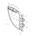
以下、この発明の好適な実施例を図1〜図6に基づいて説明する。図1は、自動車のフロント部を示している。フロント部の上面中央は上開き自在なフード1により形成され、その車幅方向両側には上面から側面に回り込んだ状態のフロントフェンダー2により形成されている。この自動車のドア3のヒンジ付近には、後方を確認するためのドアミラー4が左右両側に設けられている。
【0015】
そして、運転席の左右反対側(助手席側)のフロントフェンダー2における前方上部には、助手席側の車体側部の状態を確認するためのアンダミラー5が取付けられている。このアンダミラー5は従来よりも小型で且つ車幅方向内側に位置しており、全体がフロントフェンダー2の車幅方向における最外端Sよりも内側領域に位置するように取付けられている。
【0016】
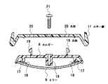
このアンダミラー5は、ハウジング6、カバー7、ホルダー8、ミラー9とから構成されている。ハウジング6は、フロントフェンダー2に固定されるベース部10と、該ベース部10の後端から一体的に立ち上げ形成されたステー部11とを有しており、全体として概略L形を呈している。ベース部10は、カバー7を被せる前に、フロントフェンダー2の下側のブラケット12に固定されることにより、フロントフェンダー2に対して固定された状態となる。すなわち、ブラケット12には、パッキン13を介して、スクリューグロメット14が予め取付けられており、このスクリューグロメット14に対してベース部10を上側からスクリュー15で固定している。
【0017】
また、前記ミラー9は、予め前記ホルダー8の周縁部に嵌め込んだ状態で取付けてある。前記ミラー9の裏側には、上下左右に4枚のスポンジテープ16が貼られており、該スポンジテープ16を介して、ホルダー8の対応位置に形成された4本の突起部17が、ミラー9を裏側から当接支持している。従って、ミラー9はガタつかず、予め設定された曲率が維持される。
【0018】
また、ホルダー8には、図5に示すように、中央に筒状部18が形成されていると共に、左右両側に前側へ延びる爪部19が形成されている。そして、ステー部11の後面の爪部19に対応する位置には孔部20が形成されている。従って、ミラー9が取付けられたホルダー8の爪部19を、ステー部11の孔部20に係合させることにより、ホルダー8をミラー9ごとステー部11に対して仮止めすることができる。仮止めした後に、ステー部11の中心から挿入したネジ21をホルダー8の筒状部18内にねじ込むことにより、ホルダー8の本格的な取付け状態が得られる。
【0019】
このようにして、ベース部10のフロントフェンダー2に対する取付けと、ステー部11に対するホルダー8の取付けが済んだ後に、ハウジング6に対してカバー7を上側から被せて、周縁をハウジング6の対応部に係合させる。このカバー7は、ベース部10の前端からステー部11にかけて流線型の表面を有しており、角張った部分がない。従って、空力の面でも有利で、燃費の向上に寄与する。
【0020】
この実施形態のアンダミラー5では、前述したように、ミラー9を予め嵌込んだホルダー8を、爪部19と孔部20により、ステー部11に対して仮止めすることができるため、ホルダー8をステー部11に対して取付ける際に、ホルダー8を手や治具で押さえておく必要がなく、ホルダー8の取付作業性が向上する。
【0021】
また、この実施形態のアンダミラー5は従来よりも小型だが、ミラー9は最適な曲率に設定されているため、運転者のアイポイントから、目的視野(車体側部の地上から1メートル付近)を十分に確認することができる。そして、このアンダミラー5のハウジング6は、ベース部10とステー部11とが一体形成された構造で、ステー部11がベース部10に対して回転する緩衝構造になっていないが、アンダミラー5の全てがフロントフェンダー2の車幅方向における最外端Sよりも内側領域に位置しているため問題ない。すなわち、アンダミラー5のいずれの部分も外側に張り出すことはなく、走行中にアンダミラー5が何かの物に当たりにくいレイアウトになっているため、アンダミラー5に緩衝機能をもたせる必要がない。そのため、この実施形態のアンダミラー5は構造が簡略になり、部品点数を低減することができるため、コスト及び組立作業性の面で有利である。
【0022】
尚、走行中に、万一、何かの物がアンダミラー5に当たっても、カバー7が流線型の表面を有するため、その物を引っかけることがない。また、アンダミラー5に対して強い衝撃が加わった場合には、スクリューグロメット14の部分が破壊されて、アンダミラー5全体が脱落するようになっているため、当たった物への衝撃を緩和することができる。
【0023】
尚、以上の実施形態では、ホルダー8に爪部19を形成し、ステー部11に孔部20を形成する例を示したが、逆にしても良い。また、ベース部10とステー部10を一体的に形成したが、ステー部11とベース部10とを別々に形成して、それらを組み付けても良い。
【0024】
【発明の効果】
この発明によれば、ミラーを取付けたホルダーを、爪部と孔部により、ステー部に対して仮止めすることができるため、ホルダーをステー部に対して取付ける際に、ホルダーを手や治具で押さえておく必要がなく、ホルダーの取付作業性が向上する。
【図面の簡単な説明】
【図1】この発明の一実施形態に係るアンダミラーの取付構造を示す自動車フロント部の平面図。
【図2】アンダミラーを示す平面図。
【図3】アンダミラーを示す後面図。
【図4】図3中矢示SA−SA線に沿う断面図。
【図5】図3中矢示SB−SB線に沿う断面図。
【図6】ホルダーをステー部に取付ける状態を示す図5相当の断面図。
【符号の説明】
2 フロントフェンダー
5 アンダミラー
6 ハウジング
7 カバー
8 ホルダー
9 ミラー
10 ベース部
11 ステー部
17 突起部
19 爪部
20 孔部
S 最外端[0001]
BACKGROUND OF THE INVENTION
The present invention relates to an undermirror for automobiles.
[0002]
[Prior art]
Some automobiles equipped with door mirrors on both the left and right sides, for example, as shown in Japanese Patent Laid-Open No. 5-301538, have an undermirror attached to the front fender front upper part on the opposite side of the driver's seat (passenger seat side). This under mirror enables the driver to check the state of the side part of the vehicle body on the passenger seat side without a large change in the viewing angle.
[0003]
This type of undermirror includes a base portion fixed to a front fender and a stay portion to which a mirror is attached on the rear surface. The mirror is fitted in a holder in advance, and attached to the stay via the holder. Specifically, the holder in which the mirror is fitted is pressed against the stay part by the operator's hand or jig, and is attached by screws inserted from the opposite side of the stay part.
[0004]
[Problems to be solved by the invention]
However, in such a conventional technique, when attaching the holder to the stay portion, it is necessary to hold the holder with a hand or a jig. Improvement was desired.
[0005]
The present invention has been made by paying attention to such a conventional technique, and provides an undermirror for an automobile capable of improving the mounting workability of a holder.
[0006]
[Means for Solving the Problems]
The invention according to
[0007]
According to the first aspect of the present invention, the holder to which the mirror is attached can be temporarily fixed to the stay portion by the claw portion and the hole portion. Therefore, when the holder is attached to the stay portion, There is no need to hold it down with hands or jigs, and the holder mounting workability is improved.
Moreover, since the base part fixed to the front fender and the stay part to which the mirror is attached are integrally formed as the housing, the number of parts can be reduced accordingly.
[0010]
In the invention according to claim 2 , the cover has a streamlined surface from the front end of the base portion to the stay portion.
[0011]
According to the second aspect of the present invention, since the cover has a streamlined surface, even if it hits something during traveling, the object will not be caught. It is also advantageous in terms of aerodynamics and contributes to improved fuel efficiency.
[0012]
According to a third aspect of the present invention, a protrusion for abutting and supporting the rear surface of the mirror is formed on the holder.
[0013]
According to the third aspect of the present invention, since the protrusion for abutting and supporting the back surface of the mirror is formed on the holder, the backlash of the mirror can be prevented.
[0014]
DETAILED DESCRIPTION OF THE INVENTION
A preferred embodiment of the present invention will be described below with reference to FIGS. FIG. 1 shows a front part of an automobile. The center of the upper surface of the front portion is formed by a
[0015]
An under
[0016]
The under
[0017]
Further, the
[0018]
As shown in FIG. 5, the
[0019]
In this way, after the
[0020]
In the
[0021]
In addition, the under
[0022]
Even if something hits the under
[0023]
In the above embodiment, the example in which the
[0024]
【The invention's effect】
According to the present invention, the holder to which the mirror is attached can be temporarily fixed to the stay portion by the claw portion and the hole portion. Therefore, when the holder is attached to the stay portion, the holder is attached to the hand or jig. There is no need to hold it down with the holder, which improves the workability of attaching the holder.
[Brief description of the drawings]
FIG. 1 is a plan view of an automobile front portion showing an undermirror mounting structure according to an embodiment of the present invention.
FIG. 2 is a plan view showing an undermirror.
FIG. 3 is a rear view showing an undermirror.
4 is a sectional view taken along the line SA-SA in FIG.
5 is a cross-sectional view taken along line SB-SB in FIG.
6 is a cross-sectional view corresponding to FIG. 5 showing a state in which the holder is attached to the stay portion.
[Explanation of symbols]
2
Claims (3)
前記ホルダーとステー部とを、いずれか一方に形成した爪部を、他方に形成した孔部に係合させることにより仮止め可能とすると共に、
前記ベース部の後端から前記ステー部を一体的に立ち上げてハウジングを形成し、かつ、前記ステー部は断面略コの字形状に形成されると共に、前記ホルダーを当該ステー部に嵌合させることで前記仮止めを行い、かつ、前記ハウジングの上側にカバーを取付けたことを特徴とする自動車のアンダミラー。An under mirror of an automobile provided with a base portion fixed to a front fender and a stay portion to which a holder fitted with a mirror is attached,
The holder and the stay part can be temporarily fixed by engaging a claw part formed on one side with a hole part formed on the other side ,
The stay portion is integrally raised from the rear end of the base portion to form a housing, and the stay portion is formed in a substantially U-shaped cross section , and the holder is fitted to the stay portion. An undermirror for automobiles , wherein the temporary fixing is performed and a cover is attached to the upper side of the housing.
前記カバーが、前記ベース部の前端から前記ステー部にかけて流線型の表面を有していることを特徴とする自動車のアンダミラー。The undermirror of an automobile according to claim 1 ,
The undermirror for automobiles, wherein the cover has a streamlined surface from the front end of the base portion to the stay portion.
前記ホルダーに、前記ミラーの裏面を当接支持する突起部を形成したことを特徴とする自動車のアンダミラー。The undermirror according to claim 1 or 2 ,
An undermirror for automobiles, wherein a protrusion is formed on the holder for abutting and supporting the back surface of the mirror.
Priority Applications (1)
| Application Number | Priority Date | Filing Date | Title |
|---|---|---|---|
| JP2000234754A JP4154841B2 (en) | 2000-08-02 | 2000-08-02 | Car under mirror |
Applications Claiming Priority (1)
| Application Number | Priority Date | Filing Date | Title |
|---|---|---|---|
| JP2000234754A JP4154841B2 (en) | 2000-08-02 | 2000-08-02 | Car under mirror |
Publications (2)
| Publication Number | Publication Date |
|---|---|
| JP2002046537A JP2002046537A (en) | 2002-02-12 |
| JP4154841B2 true JP4154841B2 (en) | 2008-09-24 |
Family
ID=18727085
Family Applications (1)
| Application Number | Title | Priority Date | Filing Date |
|---|---|---|---|
| JP2000234754A Expired - Fee Related JP4154841B2 (en) | 2000-08-02 | 2000-08-02 | Car under mirror |
Country Status (1)
| Country | Link |
|---|---|
| JP (1) | JP4154841B2 (en) |
-
2000
- 2000-08-02 JP JP2000234754A patent/JP4154841B2/en not_active Expired - Fee Related
Also Published As
| Publication number | Publication date |
|---|---|
| JP2002046537A (en) | 2002-02-12 |
Similar Documents
| Publication | Publication Date | Title |
|---|---|---|
| JP2005112171A (en) | Front body structure of automobile | |
| JPS61166746A (en) | Tonneou board fitting structure | |
| JP3820423B2 (en) | Mounting structure for vehicle lamp | |
| JP4154841B2 (en) | Car under mirror | |
| JP4406856B2 (en) | Headlamp mounting structure | |
| JP3280134B2 (en) | Automotive hood hinge mounting structure | |
| JP4154840B2 (en) | Automotive undermirror mounting structure | |
| JP3417146B2 (en) | Hood support structure for vehicles | |
| JP5152637B2 (en) | Structure of vehicle back door | |
| JP3231945B2 (en) | Car back door structure | |
| JP2007308014A (en) | Vehicle body structure | |
| JP3777827B2 (en) | Automotive outer mirror | |
| JP4275475B2 (en) | Inner mirror mounting structure | |
| JP2002347660A (en) | Mounting structure for vehicle decorative parts | |
| JP3606117B2 (en) | Front fender structure | |
| JP3821344B2 (en) | Car air bag mounting structure | |
| JP2000062668A5 (en) | ||
| JP2000190872A (en) | Undercover structure of automobile | |
| JP2606236Y2 (en) | Mall terminal processing structure | |
| JPH0134194B2 (en) | ||
| JP2000108751A (en) | Rotary assist grip for vehicles | |
| KR100319660B1 (en) | Rear combination lamp of an automobile | |
| JP4967653B2 (en) | Mirror mounting structure | |
| JP3003450B2 (en) | Rear pillar structure of vehicle | |
| JPH08119000A (en) | Mounting structure of instrument panel for vehicle |
Legal Events
| Date | Code | Title | Description |
|---|---|---|---|
| A621 | Written request for application examination |
Free format text: JAPANESE INTERMEDIATE CODE: A621 Effective date: 20050311 |
|
| A977 | Report on retrieval |
Free format text: JAPANESE INTERMEDIATE CODE: A971007 Effective date: 20071225 |
|
| A131 | Notification of reasons for refusal |
Free format text: JAPANESE INTERMEDIATE CODE: A131 Effective date: 20080108 |
|
| A521 | Written amendment |
Free format text: JAPANESE INTERMEDIATE CODE: A523 Effective date: 20080307 |
|
| TRDD | Decision of grant or rejection written | ||
| A01 | Written decision to grant a patent or to grant a registration (utility model) |
Free format text: JAPANESE INTERMEDIATE CODE: A01 Effective date: 20080617 |
|
| A01 | Written decision to grant a patent or to grant a registration (utility model) |
Free format text: JAPANESE INTERMEDIATE CODE: A01 |
|
| A61 | First payment of annual fees (during grant procedure) |
Free format text: JAPANESE INTERMEDIATE CODE: A61 Effective date: 20080630 |
|
| FPAY | Renewal fee payment (event date is renewal date of database) |
Free format text: PAYMENT UNTIL: 20110718 Year of fee payment: 3 |
|
| R150 | Certificate of patent or registration of utility model |
Ref document number: 4154841 Country of ref document: JP Free format text: JAPANESE INTERMEDIATE CODE: R150 Free format text: JAPANESE INTERMEDIATE CODE: R150 |
|
| FPAY | Renewal fee payment (event date is renewal date of database) |
Free format text: PAYMENT UNTIL: 20110718 Year of fee payment: 3 |
|
| FPAY | Renewal fee payment (event date is renewal date of database) |
Free format text: PAYMENT UNTIL: 20110718 Year of fee payment: 3 |
|
| FPAY | Renewal fee payment (event date is renewal date of database) |
Free format text: PAYMENT UNTIL: 20120718 Year of fee payment: 4 |
|
| R250 | Receipt of annual fees |
Free format text: JAPANESE INTERMEDIATE CODE: R250 |
|
| FPAY | Renewal fee payment (event date is renewal date of database) |
Free format text: PAYMENT UNTIL: 20120718 Year of fee payment: 4 |
|
| FPAY | Renewal fee payment (event date is renewal date of database) |
Free format text: PAYMENT UNTIL: 20120718 Year of fee payment: 4 |
|
| FPAY | Renewal fee payment (event date is renewal date of database) |
Free format text: PAYMENT UNTIL: 20130718 Year of fee payment: 5 |
|
| R250 | Receipt of annual fees |
Free format text: JAPANESE INTERMEDIATE CODE: R250 |
|
| R250 | Receipt of annual fees |
Free format text: JAPANESE INTERMEDIATE CODE: R250 |
|
| R250 | Receipt of annual fees |
Free format text: JAPANESE INTERMEDIATE CODE: R250 |
|
| R250 | Receipt of annual fees |
Free format text: JAPANESE INTERMEDIATE CODE: R250 |
|
| R250 | Receipt of annual fees |
Free format text: JAPANESE INTERMEDIATE CODE: R250 |
|
| R250 | Receipt of annual fees |
Free format text: JAPANESE INTERMEDIATE CODE: R250 |
|
| R250 | Receipt of annual fees |
Free format text: JAPANESE INTERMEDIATE CODE: R250 |
|
| R250 | Receipt of annual fees |
Free format text: JAPANESE INTERMEDIATE CODE: R250 |
|
| LAPS | Cancellation because of no payment of annual fees |