JP4152192B2 - High quality time scaling and pitch scaling of audio signals - Google Patents
High quality time scaling and pitch scaling of audio signals Download PDFInfo
- Publication number
- JP4152192B2 JP4152192B2 JP2002581514A JP2002581514A JP4152192B2 JP 4152192 B2 JP4152192 B2 JP 4152192B2 JP 2002581514 A JP2002581514 A JP 2002581514A JP 2002581514 A JP2002581514 A JP 2002581514A JP 4152192 B2 JP4152192 B2 JP 4152192B2
- Authority
- JP
- Japan
- Prior art keywords
- splice point
- audio signal
- samples
- audio
- segment
- Prior art date
- Legal status (The legal status is an assumption and is not a legal conclusion. Google has not performed a legal analysis and makes no representation as to the accuracy of the status listed.)
- Expired - Lifetime
Links
Images


Classifications
-
- G—PHYSICS
- G10—MUSICAL INSTRUMENTS; ACOUSTICS
- G10L—SPEECH ANALYSIS OR SYNTHESIS; SPEECH RECOGNITION; SPEECH OR VOICE PROCESSING; SPEECH OR AUDIO CODING OR DECODING
- G10L21/00—Processing of the speech or voice signal to produce another audible or non-audible signal, e.g. visual or tactile, in order to modify its quality or its intelligibility
- G10L21/04—Time compression or expansion
-
- G—PHYSICS
- G10—MUSICAL INSTRUMENTS; ACOUSTICS
- G10L—SPEECH ANALYSIS OR SYNTHESIS; SPEECH RECOGNITION; SPEECH OR VOICE PROCESSING; SPEECH OR AUDIO CODING OR DECODING
- G10L21/00—Processing of the speech or voice signal to produce another audible or non-audible signal, e.g. visual or tactile, in order to modify its quality or its intelligibility
- G10L21/003—Changing voice quality, e.g. pitch or formants
-
- H—ELECTRICITY
- H04—ELECTRIC COMMUNICATION TECHNIQUE
- H04N—PICTORIAL COMMUNICATION, e.g. TELEVISION
- H04N5/00—Details of television systems
- H04N5/44—Receiver circuitry for the reception of television signals according to analogue transmission standards
- H04N5/60—Receiver circuitry for the reception of television signals according to analogue transmission standards for the sound signals
-
- G—PHYSICS
- G10—MUSICAL INSTRUMENTS; ACOUSTICS
- G10H—ELECTROPHONIC MUSICAL INSTRUMENTS; INSTRUMENTS IN WHICH THE TONES ARE GENERATED BY ELECTROMECHANICAL MEANS OR ELECTRONIC GENERATORS, OR IN WHICH THE TONES ARE SYNTHESISED FROM A DATA STORE
- G10H2210/00—Aspects or methods of musical processing having intrinsic musical character, i.e. involving musical theory or musical parameters or relying on musical knowledge, as applied in electrophonic musical tools or instruments
- G10H2210/325—Musical pitch modification
-
- G—PHYSICS
- G10—MUSICAL INSTRUMENTS; ACOUSTICS
- G10H—ELECTROPHONIC MUSICAL INSTRUMENTS; INSTRUMENTS IN WHICH THE TONES ARE GENERATED BY ELECTROMECHANICAL MEANS OR ELECTRONIC GENERATORS, OR IN WHICH THE TONES ARE SYNTHESISED FROM A DATA STORE
- G10H2210/00—Aspects or methods of musical processing having intrinsic musical character, i.e. involving musical theory or musical parameters or relying on musical knowledge, as applied in electrophonic musical tools or instruments
- G10H2210/375—Tempo or beat alterations; Music timing control
-
- G—PHYSICS
- G10—MUSICAL INSTRUMENTS; ACOUSTICS
- G10H—ELECTROPHONIC MUSICAL INSTRUMENTS; INSTRUMENTS IN WHICH THE TONES ARE GENERATED BY ELECTROMECHANICAL MEANS OR ELECTRONIC GENERATORS, OR IN WHICH THE TONES ARE SYNTHESISED FROM A DATA STORE
- G10H2250/00—Aspects of algorithms or signal processing methods without intrinsic musical character, yet specifically adapted for or used in electrophonic musical processing
- G10H2250/541—Details of musical waveform synthesis, i.e. audio waveshape processing from individual wavetable samples, independently of their origin or of the sound they represent
-
- G—PHYSICS
- G10—MUSICAL INSTRUMENTS; ACOUSTICS
- G10L—SPEECH ANALYSIS OR SYNTHESIS; SPEECH RECOGNITION; SPEECH OR VOICE PROCESSING; SPEECH OR AUDIO CODING OR DECODING
- G10L25/00—Speech or voice analysis techniques not restricted to a single one of groups G10L15/00 - G10L21/00
- G10L25/78—Detection of presence or absence of voice signals
- G10L25/87—Detection of discrete points within a voice signal
-
- H—ELECTRICITY
- H04—ELECTRIC COMMUNICATION TECHNIQUE
- H04N—PICTORIAL COMMUNICATION, e.g. TELEVISION
- H04N5/00—Details of television systems
- H04N5/04—Synchronising
Landscapes
- Engineering & Computer Science (AREA)
- Quality & Reliability (AREA)
- Multimedia (AREA)
- Signal Processing (AREA)
- Acoustics & Sound (AREA)
- Audiology, Speech & Language Pathology (AREA)
- Human Computer Interaction (AREA)
- Physics & Mathematics (AREA)
- Health & Medical Sciences (AREA)
- Computational Linguistics (AREA)
- Compression, Expansion, Code Conversion, And Decoders (AREA)
- Measurement Of Mechanical Vibrations Or Ultrasonic Waves (AREA)
- Stereophonic System (AREA)
- Signal Processing For Digital Recording And Reproducing (AREA)
- Electrophonic Musical Instruments (AREA)
- Electrically Operated Instructional Devices (AREA)
Abstract
Description
本発明は、オーディオ信号のサイコアコースティックな処理の分野に関する。とりわけ、本発明は、オーディオ信号のタイムスケーリング及び/又はピッチスケーリング(ピッチシフティング)をどこでどのように実行するかに関する。特に、本処理はディジタルオーディオ信号のような、サンプリングされたオーディオ信号に適用される。本発明はまた、オーディオを各々別々に認識されるような「聴覚的イベント」に分割することに関する。 The present invention relates to the field of psychoacoustic processing of audio signals. In particular, the present invention relates to where and how to perform time scaling and / or pitch scaling (pitch shifting) of an audio signal. In particular, this process is applied to sampled audio signals, such as digital audio signals. The invention also relates to dividing audio into “auditory events” that are each recognized separately.
タイムスケーリングは、スペクトル内容(音色の認識)、もしくは、知覚された信号のピッチ(ここでピッチとは、周期的なオーディオ信号に関連する特徴である)を変化させないで、オーディオ信号の時間的展開又は継続時間を変化させることに関するものである。ピッチスケーリングは、オーディオ信号の時間展開又は継続時間に影響を与えないで、オーディオ信号のスペクトル内容、もしくは、知覚された信号のピッチを変化させることに関するものである。タイムスケーリング及びピッチスケーリングは、お互いに二元的な方法である。例えば、オーディオ信号を5%タイムスケーリングすることで信号継続時間を増加させ、そして、5%高いサンプルレートで(例えば再サンプルにより)サンプル値を読み取り、それによりそのオリジナルな信号継続時間を維持させるようにしながら、ディジタル化されたオーディオシグナルのピッチをその継続時間に影響を与えることなく5%スケールアップすることが可能である。この結果としての信号は、オリジナルの信号と同じ継続時間となるが、修正されたピッチあるいはスペクトル特性となる。以下にさらに議論する通り、再サンプリングが適用されることもあるが、一定の出力サンプリングレート又は入出力サンプリングレートを同じにすることが要求されないなら、再サンプリングは本質的なステップではない。 Time scaling is the temporal evolution of an audio signal without changing the spectral content (timbre recognition) or the perceived signal pitch (where pitch is a characteristic associated with a periodic audio signal). Or it relates to changing the duration. Pitch scaling relates to changing the spectral content of an audio signal or the perceived pitch of the signal without affecting the time evolution or duration of the audio signal. Time scaling and pitch scaling are two ways of each other. For example, increasing the signal duration by time scaling the audio signal by 5%, and reading the sample value at a 5% higher sample rate (eg, by re-sampling), thereby maintaining its original signal duration However, it is possible to scale up the pitch of the digitized audio signal by 5% without affecting its duration. The resulting signal has the same duration as the original signal, but with a modified pitch or spectral characteristic. As discussed further below, resampling may be applied, but resampling is not an essential step if it is not required to have a constant output sampling rate or input / output sampling rate the same.
オーディオ信号の時間とピッチの特性を独立に制御する品質の高い方法は、多くの用途がある。このことは、とりわけ、単純な音色の信号から音声信号や複雑な音楽に至るまでの広いレンジの内容を含む忠実度の高いマルチチャンネルオーディオにおいて真実である。時間とピッチのスケーリングの用途は、音声/映像の放送、音声/映像のポストプロダクション、同期化、マルチトラックオーディオ記録及びミキシングを含んでいる。音声/映像の放送とポストプロダクションにおいて、映像を発信元の素材とは違ったレートで再生することは、その結果オーディオ信号もそれに伴ってピッチスケーリングされたものとなるが、必要なことであろう。発信元の素材の音色とピッチとを維持した状態で、オーディオのピッチスケーリングは、オーディオと映像との同期を保持することができる。マルチトラックオーディオまたは音声/映像のポストプロダクションにおいて、オーディオまたは映像の断片における時間制約的な継続時間とマッチした新しい素材を必要とするかもしれない。オーディオのタイムスケーリングは、音源の音色とピッチを変更しないためには、オーディオの新たな断片を時間的に拘束することがある。 A high quality method for independently controlling the time and pitch characteristics of an audio signal has many applications. This is particularly true in high-fidelity multi-channel audio that includes a wide range of content ranging from simple timbre signals to audio signals and complex music. Applications for time and pitch scaling include audio / video broadcast, audio / video post-production, synchronization, multi-track audio recording and mixing. In audio / video broadcasts and post-production, it may be necessary to play the video at a different rate than the source material, resulting in the audio signal being pitch scaled accordingly. . Audio pitch scaling can maintain synchronization between audio and video while maintaining the tone and pitch of the source material. In multi-track audio or audio / video post-production, new material that matches the time-constrained duration in audio or video fragments may be required. In audio time scaling, in order not to change the tone color and pitch of the sound source, a new piece of audio may be constrained in time.
本発明の特徴によれば、オーディオ信号のタイムスケーリング及び/又はピッチシフティングの方法が提供される。この信号は、多数のサイコアコースティックな基準を用いて分析され、オーディオ信号のタイムスケーリング及び/又はピッチシフティング過程において、まったく音が聞こえないか又は最小限の音しか聞こえないような、オーディオ信号の領域が特定され、そしてこの領域内で、この信号は、タイムスケーリング及び/又はピッチシフティングされる。 According to a feature of the invention, a method for time scaling and / or pitch shifting of an audio signal is provided. This signal is analyzed using a number of psychoacoustic criteria, and the audio signal is such that no or only minimal sound is heard during the time scaling and / or pitch shifting process of the audio signal. An area is identified, and within this area, the signal is time scaled and / or pitch shifted.
本発明の更なる特徴によれば、多数チャンネルのオーディオ信号のタイムスケーリング及び/又はピッチシフティングの方法が提供される。オーディオ信号の各チャンネルは、少なくとも1つののサイコアコースティックな基準を用いて分析され、オーディオ信号のタイムスケーリング及び/又はピッチシフティング過程において、まったく音が聞こえないか又は最小限の音しか聞こえないような、オーディオ信号のチャンネルにおける領域が特定され、そして、オーディオ信号の複数チャンネルのすべてにおいて、タイムスケーリング及び/又はピッチシフティングが、オーディオ信号チャンネルの少なくとも1つの特定された領域内にあるタイムセグメント期間中になされる。 According to a further feature of the present invention, a method for time scaling and / or pitch shifting of a multi-channel audio signal is provided. Each channel of the audio signal is analyzed using at least one psychoacoustic criterion so that no or minimal sound can be heard during the time scaling and / or pitch shifting process of the audio signal. A time segment period in which a region in the channel of the audio signal is specified, and in all of the plurality of channels of the audio signal, time scaling and / or pitch shifting is within at least one specified region of the audio signal channel Made inside.
本発明の更なる特徴によれば、オーディオ信号が聴覚イベントに分割され、聴覚イベント内でその信号がタイムスケール及び/又はピッチシフトされるようにした、オーディオ信号のタイムスケーリング及び/又はピッチシフティングの方法が提供される。 According to a further feature of the present invention, the audio signal is time-scaled and / or pitch-shifted such that the audio signal is divided into auditory events, such that the signal is time-scaled and / or pitch-shifted within the auditory event. A method is provided.
本発明の更に別の特徴によれば、各チャンネルのオーディオ信号が聴覚イベントに分割されるようにした、複数チャンネルのオーディオ信号のタイムスケーリング及び/又はピッチシフティングの方法が提供される。結合された聴覚イベントが決定され、あらゆるオーディオ信号チャンネル内に聴覚イベントの境界が現れたとき、各聴覚イベントは境界を持つ。すべてのオーディオ信号チャンネルは、結合された聴覚イベント内でタイムスケール及び/又はピッチシフトされ、このようなタイムスケーリング及び/又はピッチシフティングは、各チャンネルの聴覚イベント内にとどまる。 According to yet another aspect of the invention, a method for time scaling and / or pitch shifting of a multi-channel audio signal is provided, wherein the audio signal of each channel is divided into auditory events. Each auditory event has a boundary when a combined auditory event is determined and an auditory event boundary appears in every audio signal channel. All audio signal channels are time scaled and / or pitch shifted within the combined auditory event, and such time scaling and / or pitch shifting remains within each channel's auditory event.
本発明のなお更なる特徴によれば、オーディオ信号が聴覚イベントに分割され、聴覚イベントは、サイコアコースティックな基準を用いて分析され、オーディオ信号のタイムスケーリング及び/又はピッチシフティング過程において、まったく音が聞こえないか又は最小限の音しか聞こえないような聴覚イベントを特定するオーディオ信号のタイムスケーリング及び/又はピッチシフティングの方法が提供される。タイムスケーリング及び/又はピッチシフティングのプロセスは、オーディオ信号のタイムスケーリング及び/又はピッチシフティング過程が、まったく音が聞こえないか又は最小限の音しか聞こえないようなものとみなされる聴覚イベント内でなされる。 According to a still further feature of the invention, the audio signal is divided into auditory events, which are analyzed using psychoacoustic criteria, and in the time scaling and / or pitch shifting process of the audio signal, no sound is generated. A method of time-scaling and / or pitch-shifting an audio signal that identifies an auditory event where the user cannot hear or hear minimal sound is provided. The time-scaling and / or pitch-shifting process is performed within an auditory event where the time-scaling and / or pitch-shifting process of the audio signal is considered such that no sound can be heard or only minimal sound can be heard. Made.
本発明のなお更なる特徴によれば、各チャンネルのオーディオ信号が聴覚イベントに分割されるようにした、多数チャンネルのオーディオ信号のタイムスケーリング及び/又はピッチシフティングの方法が提供される。聴覚イベントは、少なくとも1つのサイコアコースティックな基準を用いて分析され、オーディオ信号のタイムスケーリング及び/又はピッチシフティング過程において、まったく音が聞こえないか又は最小限の音しか聞こえないような、聴覚イベントを特定する。結合された聴覚イベントが決定され、あらゆるオーディオ信号チャンネル内に聴覚イベントの境界が現れたところに、各聴覚イベントは境界を持つ。タイムスケーリング及び/又はピッチシフティングのプロセスは、多数チャンネルにおけるオーディオ信号のタイムスケーリング及び/又はピッチシフティング過程が、まったく音が聞こえないか又は最小限の音しか聞こえないようなものとみなされる結合された聴覚イベント内でなされる。 According to still further features of the invention, a method for time scaling and / or pitch shifting of a multi-channel audio signal is provided, wherein each channel's audio signal is divided into auditory events. Auditory events are analyzed using at least one psychoacoustic criterion, such that at the time of audio signal time-scaling and / or pitch-shifting process, no or only minimal sounds are heard Is identified. Each auditory event has a boundary where a combined auditory event is determined and an auditory event boundary appears in every audio signal channel. The time scaling and / or pitch shifting process is a combination where the time scaling and / or pitch shifting process of an audio signal in multiple channels is considered to be inaudible or minimally audible. Made within an auditory event.
本発明のなお更なる特徴によれば、多数のサイコアコースティックな基準に基づくオーディオ信号の分析は、オーディオ信号を分析し、オーディオが一群のサイコアコースティックな基準のうちの少なくとも1つを満足するようなオーディオ信号の領域を決定することを含んでいる。 According to still further features of the invention, the analysis of the audio signal based on a number of psychoacoustic criteria analyzes the audio signal such that the audio satisfies at least one of the group of psychoacoustic criteria. Including determining an area of the audio signal.
本発明のさらになお更なる特徴によれば、サイコアコースティックな基準は以下の内の1以上を含む。(1)特定された領域のオーディオ信号はトランジエントの結果として、実質的にプレマスクあるいはポストマスクされる。(2)特定された領域のオーディオ信号は実質的に非可聴である。(3)特定された領域のオーディオ信号は、主として高周波域にある。そして、(4)特定された領域のオーディオ信号は、そこでは、そのオーディオ信号に先立つ及び/又はそれに続くセグメントの一部分の方が大きくなっているような、オーディオ信号のセグメントのより静かな部分である。サイコアコースティックなマスキングの原則的な基準は以下に論ずる。 According to still further features of the invention, the psychoacoustic criteria includes one or more of the following. (1) The audio signal in the specified area is substantially pre-masked or post-masked as a result of the transient. (2) The audio signal in the specified area is substantially inaudible. (3) The audio signal in the specified region is mainly in the high frequency region. And (4) the audio signal in the specified region is a quieter portion of the segment of the audio signal where there is a larger portion of the segment preceding and / or following the audio signal. is there. The principle criteria for psycho-acoustic masking are discussed below.
本発明の特徴は、タイムスケーリング及び/又はピッチシフティングのプロセスの結果としてのアーティファクトの可聴性を高める下向きの順番(つまり、判断基準の上下関係)に、一群のサイコアコースティックな基準が整えられることである。本発明のもう1つの特徴によれば、最も高いランキングのサイコアコースティックな基準(つまり、最小の可聴アーティファクトを導く基準)を満足するときの領域が特定される。あるいは、1つの基準を満足していたとしても、基準を満足するオーディオにおける他の1以上の領域を特定するために他の基準を探し出すこともできる。後者のアプローチは、マルチチャンネルオーディオにおいて、多数チャンネル間で可能性のある共通のスプライスポイントが現れるよう階層をさらに下げた基準も含めて、あらゆる基準を満足するすべての可能性のある領域の位置を特定するために役に立つ。 A feature of the present invention is that a group of psychoacoustic criteria are arranged in a downward order (ie, the top-to-bottom relationship of the criteria) that increases the audibility of artifacts as a result of the process of time scaling and / or pitch shifting. It is. According to another aspect of the present invention, an area is identified when it satisfies the highest ranking psychoacoustic criterion (ie, the criterion that leads to the smallest audible artifact). Alternatively, even if one criterion is satisfied, other criteria can be found to identify one or more other regions in the audio that satisfy the criterion. The latter approach can be used to locate all possible regions in multi-channel audio that meet all criteria, including those that are further down the hierarchy so that possible common splice points appear across multiple channels. Useful for identifying.
本発明の特徴は他のタイプのタイムスケーリング及び/又はピッチシフティングのプロセス(例えば、US特許No.6,266,033B1を見よ、この特許は全体としてここに組み込まれている)を利用するかもしれないが、本発明の特徴はタイムスケーリング及び/又はピッチシフティングのプロセスを効果的に利用し、
スプライスポイントがオーディオ信号の領域内で選択され、それにより時間内にスプライスポイントを導くオーディオ信号のリーディングセグメントを定義し、
スプライスポイントから間隔を空けてエンドポイントが選択され、それにより時間内にエンドポイントを追跡するオーディオ信号の追跡セグメントと、スプライスポイントとエンドポイントの間にオーディオ信号のターゲットセグメントを定義し、
リーディングセグメントと追跡セグメントはスプライスポイントで結合され、それにより、エンドポイントが前記スプライスポイントより時間的に遅くなったとき(より多いサンプル数を持つ)、ターゲットセグメントを削除すること、あるいは、エンドポイントが前記スプライスポイントより時間的に早くなったとき、ターゲットセグメントを繰返すことで継続時間を長くする(サンプル数を増加する)ことで、オーディオ信号の継続時間を短くし(サンプルにより代表させるディジタルオーディオの場合は、オーディオ信号のサンプル数を少なくする)、そして
要求するタイムスケーリング及び/又はピッチシフティングをもたらすレートで、結合されたリーディングセグメントと追跡セグメントを読み取る。
While features of the present invention may utilize other types of time scaling and / or pitch shifting processes (see, eg, US Pat. No. 6,266,033B1, which is incorporated herein in its entirety). The features of the present invention effectively utilize the process of time scaling and / or pitch shifting,
A splice point is selected within the region of the audio signal, thereby defining a leading segment of the audio signal that leads the splice point in time;
An endpoint is selected at a distance from the splice point, thereby defining a tracking segment of the audio signal that tracks the endpoint in time, and a target segment of the audio signal between the splice point and the endpoint,
The leading and tracking segments are joined at the splice point, so that when the endpoint is later in time than the splice point (with a larger number of samples), the target segment can be deleted, or the endpoint When the time is earlier than the splice point, the duration of the audio signal is shortened by increasing the number of samples by repeating the target segment (in the case of digital audio represented by samples). Reduces the number of samples in the audio signal) and reads the combined reading and tracking segments at a rate that provides the required time scaling and / or pitch shifting.
結合されたリーディングセグメントと追跡セグメントは、
オリジナルの継続時間と同じ継続時間がオーディオ信号のピッチシフティングとなり、
ターゲットセグメントが削除されたばあいは、サンプル数の減少に関係する変化と同じ比率で減少した継続時間がオーディオ信号の時間圧縮となり、
ターゲットセグメントが繰返されたばあいは、サンプル数の増加に関係する変化と同じ比率で増加した継続時間がオーディオ信号の時間拡張となり、
サンプル数の減少に関係する変化とは別の比率で減少した継続時間がオーディオ信号の時間圧縮及びオーディオ信号のピッチシフティングとなり、あるいは
サンプル数の増加に関係する変化とは別の比率で増加した継続時間がオーディオ信号の時間拡張及びオーディオ信号のピッチシフティングとなる
ようなレートで読み取られる。
The combined leading and tracking segments are
The same duration as the original duration is pitch shifting of the audio signal,
If the target segment is deleted, the duration of the audio signal is time-compressed, with the duration decreasing at the same rate as the change related to the decrease in the number of samples,
If the target segment is repeated, the duration that increases at the same rate as the change related to the increase in the number of samples is the time extension of the audio signal,
Duration reduced at a rate different from the change related to the decrease in the number of samples results in time compression of the audio signal and pitch shifting of the audio signal, or increased at a rate different from the change related to the increase in the number of samples It is read at a rate such that the duration is time extension of the audio signal and pitch shifting of the audio signal.
ターゲットセグメントが削除されたとしても(データ圧縮)繰返されたとしても(データ拡張)、1つのスプライスポイントと1つのスプライスしか存在しない。ターゲットセグメントが削除された場合、スプライスは、スプライスポイントと削除されたターゲットセグメントのエンドポイントとが結合あるいはスプライスされるところに存在する。ターゲットセグメントが繰返された場合、それでもただ1つのスプライスしか存在しない。すなわち、そのスプライスは、ターゲットセグメント(スプライスポイント)の最初の演奏の終了点が、ターゲットセグメントの2番目の演奏の開始点(エンドポイント)に当たる。オーディオのサンプル数を減少する場合は(データ圧縮)、プレマスキング又はポストマスキングの基準のために、エンドポイントは(常に特定された領域内にあるスプライスポイントに加えて)特定された領域内にある事が望ましい。スプライスポイントがトランジエントによりプレマスキング又はポストマスキングされるような圧縮の場合、エンドポイントは、特定された領域内にある必要はない。他の場合は(以下に述べるように、聴覚イベント内に処理が行われる場合を除く)、可聴なものが削除されたり繰返されたりしないように、エンドポイントは特定された領域内にあることが望ましい。オーディオのサンプル数を増加する場合は(データ拡張)、オリジナルオーディオにおけるエンドポイントは特定された領域内にあることが望ましい。以下に記載の通り、スプライスポイントとしての可能性がある位置は、最も早い時間と最も遅い時間を持ち、エンドポイントとしての可能性がある位置は、最も早い時間と最も遅い時間を持つ。オーディオが、バッファメモリ内のデータのブロック内にあるサンプルにより代表される場合は、スプライスポイントとしての可能性がある位置は、おのおの、ブロック内で最大と最小の位置を持ち、エンドポイントもブロック内で最大と最小の位置を持ち、おのおのが最も早いエンドポイント時間と最も遅いエンドポイント時間を代表する。 Even if the target segment is deleted (data compression) and repeated (data expansion), there is only one splice point and one splice. If the target segment is deleted, the splice exists where the splice point and the deleted target segment end point are combined or spliced. If the target segment is repeated, there is still only one splice. That is, in the splice, the end point of the first performance of the target segment (splice point) corresponds to the start point (end point) of the second performance of the target segment. When reducing the number of audio samples (data compression), the endpoint is in the specified area (in addition to the splice points that are always in the specified area) due to pre-masking or post-masking criteria Things are desirable. In the case of compression where the splice point is pre-masked or post-masked by the transient, the endpoint need not be within the specified region. In other cases (except where processing occurs within an auditory event, as described below), the endpoint may be within a specified area so that audible objects are not deleted or repeated. desirable. When increasing the number of audio samples (data expansion), it is desirable that the end point in the original audio is within the specified area. As described below, a potential location as a splice point has the earliest time and the latest time, and a potential location as an endpoint has the earliest time and the latest time. If the audio is represented by a sample in a block of data in the buffer memory, each possible position as a splice point has a maximum and minimum position in the block, and the endpoint is also in the block. With the maximum and minimum positions, each representing the earliest and latest endpoint times.
マルチチャンネルのオーディオ処理において、指示のための合図を妨げないために、チャンネル間での相対的な振幅と位相の関係は維持しておくことが望ましい。従って、1つのチャンネルにおいてオーディオのターゲットセグメントが削除又は繰返された場合、他のチャンネルでそれに対応するセグメント(同じサンプルインデックスを持っている)も削除又は繰返される。すべてのチャンネルで非可聴なスプライシングを許可する、すべてのチャンネルに実質的に共通のターゲットセグメントを見つけることが必要である。
In multi-channel audio processing, it is desirable to maintain the relative amplitude and phase relationship between the channels in order not to interfere with indication cues. Therefore, when an audio target segment is deleted or repeated in one channel, the corresponding segment (having the same sample index) is deleted or repeated in the other channel. It is necessary to find a target segment that is substantially common to all channels, allowing inaudible splicing on all channels.
定義
本明細書において、「データ圧縮」とは、セグメントを削除してサンプル数を減少し、時間を縮めることを意味し、「データ拡張」とは、セグメントを繰返してサンプル数を増加し、時間を拡張することを意味する。オーディオの「領域」、「セグメント」及び「ポーション」は各々、シングルチャンネルからの、概念的には時間における2つの瞬間の間(ある瞬間から次の瞬間までの期間)のオーディオの、有限的に連続する部分を表現する。このような、領域、セグメントあるいはポーションは、連続的な標本値又はインデックス番号を持つサンプルで代表することができる。「特定された領域」とは、サイコアコースティックな基準により特定され、スプライスポイント及び普通はエンドポイントがあるオーディオの領域、セグメント又はポーションを意味する。「相関処理領域」とは、エンドポイント、もしくはスプライスポイント及びエンドポイント、を見つけるために相関関係の算定をするための領域、セグメント又はポーションを意味する。「サイコアコースティックな基準」には、時間領域におけるマスキング、周波数領域におけるマスキング、及び/又は他のサイコアコースティックな要因をベースとする基準が含まれる。以上に説明した通り、「ターゲットセグメント」は、データ圧縮の際には削除され、あるいは、データ拡張の際には繰返されるオーディオの部分を意味する。
Definitions In this specification, “data compression” means deleting a segment to reduce the number of samples and shortening the time, and “data expansion” means repeating the segment to increase the number of samples, and time. Means to extend. Audio “regions”, “segments” and “potions” are each finitely limited in audio from a single channel, conceptually between two moments in time (the period from one moment to the next). Represents a continuous part. Such regions, segments or portions can be represented by samples with consecutive sample values or index numbers. “Identified region” means a region, segment or portion of audio identified by psychoacoustic criteria and having a splice point and usually an end point. “Correlation processing area” means an area, segment or portion for calculating a correlation in order to find an end point, or a splice point and an end point. “Psychoacoustic criteria” includes criteria based on masking in the time domain, masking in the frequency domain, and / or other psychoacoustic factors. As described above, the “target segment” means a portion of audio that is deleted during data compression or repeated during data expansion.
マスキング
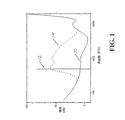
本発明の特徴は、人間の聴覚と、特に、マスキングとして知られているサイコアコースティックな現象をうまく利用するものである。簡易化されたマスキングの概念は図1及び以下の議論により把握することができる。図1中の実線は、そのレベルにおける正弦曲線や峡帯域ノイズのようなオーディオがちょうど聞こえるオーディオレベルすなわち、聴覚の閾値を示している。この曲線より上部にある音は可聴であり、下部にある音は可聴ではない。この閾値は明らかに大きく周波数に依存する。例えば4kHzでは、50Hzや15kHzの音に比べてはるかに小さな音も聞くことができる。25kHzにおいては、閾値はスケールを外れており、どんなに大きな音も聞こえない。
Masking Features of the present invention make good use of human hearing and, in particular, a psychoacoustic phenomenon known as masking. The simplified masking concept can be understood from FIG. 1 and the following discussion. The solid line in FIG. 1 indicates the audio level at which audio such as a sine curve and gorgeous band noise at that level can be heard, that is, the threshold of hearing. The sound above this curve is audible and the sound below is not audible. This threshold is clearly largely frequency dependent. For example, at 4 kHz, a much smaller sound can be heard as compared with sounds at 50 Hz and 15 kHz. At 25 kHz, the threshold is off scale and no loud sound can be heard.
1つの周波数における比較的大きな信号、例えば、12で示した500Hzの正弦波の存在下での閾値を考える。修正された閾値14は、500Hzにじかに接している付近においては劇的に、周波数が離れたところではそこそこに上昇しており、可聴域から遠く離れた部分ではまったく上昇していない。
Consider a threshold in the presence of a relatively large signal at one frequency, for example, a 500 Hz sine wave shown at 12. The modified
この閾値の上昇は、マスキングと呼ばれる。500Hzの大きな正弦波信号(「マスキングシグナル」又は「マスカー」)の存在下では、「マスキングスレッシュホールド」と称されるこの閾値以下の信号は、大きな信号により、隠されるか又はマスクされる。さらに少し離れても、信号が無いときの閾値よりレベルがいくぶん上昇するが、新しいマスクされた閾値より小さい他の信号は、聞こえない。しかし、信号が無いときの閾値が変化しないような離れた周波数帯において、500Hzのマスカーが無い状態で聞こえるオーディオは、500Hzのマスカーがあってもなお聞こえる。従って、マスキングは単に1以上のマスキングシグナルの存在に依存するのではなく、周波数帯域の広がりに依存する。ある音楽のパッセージには、例えば、可聴領域全域に広がる周波数の成分が含まれており、従って、シグナルが無いときの閾値の曲線と比較してあらゆるところで上昇したマスクされた閾値を与える。他の音楽のパッセージには、例えば、周波数帯の狭い部分に限定された成分の周波数の成分をもつ単一の楽器からの比較的大きなオーディオを含んでおり、従って、図1に例示した正弦波のマスカーに似たマスクされた閾値を与える。 This increase in threshold is called masking. In the presence of a large 500 Hz sinusoidal signal (“masking signal” or “masker”), signals below this threshold, referred to as “masking threshold”, are hidden or masked by the large signal. Even further away, the level is somewhat higher than the threshold when there is no signal, but other signals below the new masked threshold are not audible. However, audio that can be heard without a 500 Hz masker in a distant frequency band where the threshold when there is no signal does not change is still audible even with a 500 Hz masker. Thus, masking does not depend solely on the presence of one or more masking signals, but on the spread of the frequency band. Some musical passages contain, for example, a frequency component that extends throughout the audible region, thus giving a masked threshold that is elevated everywhere compared to the threshold curve when there is no signal. Other musical passages include, for example, relatively large audio from a single musical instrument having a frequency component that is limited to a narrow portion of the frequency band, and thus the sine wave illustrated in FIG. Gives a masked threshold similar to the masker.
マスキングは、マスカーとマスキングされる信号との間の時間関係に依存する、時間的側面を持っている。あるマスキングシグナルは、本質的にマスキングシグナルが存在するときのみにマスキングを行う(「同時マスキング」)。他のマスキングシグナルは、マスカーが存在するときのみならず、時間的にそれより早いとき(「バックワードマスキング」又は「プレマスキング」)及び、時間的にそれより遅いときにも(「フォワードマスキング」又は「ポストマスキング」)マスキングを行う。「トランジエント」すなわち、突然の短時間で大幅な信号レベルの上昇には、これら3つの「タイプ」すべてのマスキング、つまり、バックワードマスキング、同時マスキング、及びフォワードマスキングが現れる。一方、定常状態あるいは準定常状態においては、同時マスキングのみ現れる。本発明の関連で、トランジエントの結果による同時マスキングを利用するべきではない。なぜなら、それと同時に、あるいは、それとほぼ同時にスプライスすることにより、トランジエントに外乱を与えることは好ましくないからである。 Masking has a temporal aspect that depends on the temporal relationship between the masker and the signal to be masked. Some masking signals mask only when there is essentially a masking signal ("simultaneous masking"). Other masking signals are not only when a masker is present, but also earlier in time (“backward masking” or “premasking”) and later in time (“forward masking”). Or “post masking”) masking is performed. “Transient”, that is, a sudden and rapid increase in signal level, manifests all three “types” of masking: backward masking, simultaneous masking, and forward masking. On the other hand, only the simultaneous masking appears in the steady state or the quasi-steady state. In the context of the present invention, simultaneous masking with transient results should not be used. This is because it is not preferable to give a disturbance to the transient by splicing at the same time or almost at the same time.
オーディオのトランジエントは、フォワード及びバックワードの両方の時間的マスキングを行うことは、知られている。トランジエントオーディオ素材が、直接トランジエントに先立つオーディオ及び続くオーディオのようなトランジエントの前後の可聴オーディオ素材をマスクすることは、リスナーには知覚されない。(トランジエントによる同時マスキングは、繰返しを避けるため又はトランジエントを乱すためには用いられない。)プレマスキングは、測定されており、比較的短くほんの数msec(ミリセカンド)であり、一方、ポストマスキングは50msec以上続く。ポストマスキングはより長く続くので、一般的にポストマスキングの方がより有用であるにもかかわらず、「プレ」と「ポスト」の両方のトランジエントマスキングが、本発明に関連して活用される。 It is known that audio transients perform both forward and backward temporal masking. It is not perceived by the listener that the transient audio material masks the audible audio material before and after the transient, such as the audio directly preceding the transient and the following audio. (Simultaneous masking with transients is not used to avoid repetition or to disturb transients.) Premasking is measured and is relatively short, only a few milliseconds (milliseconds), while post Masking continues for more than 50 msec. Since postmasking lasts longer, both “pre” and “post” transient masking are exploited in connection with the present invention, although postmasking is generally more useful.
本発明の1つの特徴は、トランジエントの検出にある。下記に記載の現実の実施において、サブブロック(ひとかたまりのオーディオサンプルの一部)が調べられる。振幅の程度は、その点までの信号の振幅を代表する平滑化された移動平均値と比較される。演算は、高周波のトランジエントがより大きな低周波の信号により薄められ、そのため、消えてしまうことがないよう、全周波領域での演算と高周波領域のみでの演算とを分けて実行される。あるいは、トランジエントを検出する適当な公知の方法を採用しても良い。 One feature of the present invention resides in transient detection. In the actual implementation described below, sub-blocks (parts of a group of audio samples) are examined. The magnitude of the amplitude is compared with a smoothed moving average value representative of the amplitude of the signal up to that point. The calculation is performed separately for the calculation in the entire frequency region and the calculation only in the high frequency region so that the high frequency transient is diluted by a larger low frequency signal and therefore does not disappear. Alternatively, an appropriate known method for detecting a transient may be adopted.
スプライスは、時間と共に消滅する周波数の幅を持ったアーティファクトとなるような外乱を生じることがある。スプライシングによるアーティファクトの周波数の幅(及び振幅)は、(1)スプライスされた信号の周波数の幅(以下にさらに議論するように、アーティファクトは、スプライスされた信号の周波数の幅とは違った周波数の幅を潜在的に持っていることが認められる)、(2)スプライスポイントで繋がれたとき波形が一致するところまでの広がり、および(3)スプライスポイントで波形が繋がれたところでのクロスフェードの形及び持続時間に依存する。本発明の特徴によるクロスフェードについてはさらに以下に述べる。接続点における波形の一致を補助する相関技法についても以下に述べる。本発明の1つの特徴によれば、スプライシングによるアーティファクトがマスクされるか聞こえないようにするか又は少ししか聞こえないようにすることが望ましい。本発明により意図されたサイコアコースティックな基準は、アーティファクトがマスクされるか聞こえないようにするか又は少ししか聞こえないようにするような特徴を具備している。非可聴性或いは最小限の可聴性はマスキングのタイプと考えられる。マスキングは、アーティファクトがマスキング信号によるマスキング閾値以下(あるいは、マスキング信号が無いときは、信号が無いときの可聴閾値以下、これもマスキングの形式となると考えてよい)になるよう時間と周波数を限定する必要がある。アーティファクトの継続時間は、まず得られた近似として、本質的にはクロスフェードの長さ(継続時間)と定義される。クロスフェードが遅くなればなるほど、周波数帯域が狭くなるがその継続時間は長くなる。 Splices can cause disturbances that result in artifacts with a frequency range that disappears over time. The frequency width (and amplitude) of splicing artifacts is: (1) the frequency width of the spliced signal (as discussed further below, the artifact has a frequency different from the frequency width of the spliced signal. (2) the spread to the point where the waveforms match when connected at the splice point, and (3) the crossfade where the waveform is connected at the splice point Depends on shape and duration. The crossfade according to the features of the present invention will be further described below. A correlation technique that assists in matching the waveforms at the connection points is also described below. In accordance with one aspect of the present invention, it is desirable to prevent splicing artifacts from being masked or inaudible. The psychoacoustic criteria contemplated by the present invention have features that make the artifacts masked or inaudible or only inaudible. Non-audible or minimal audibility is considered a type of masking. Masking limits time and frequency so that the artifacts are below the masking threshold by the masking signal (or below the audible threshold when there is no signal, which can also be considered as a form of masking). There is a need. The duration of the artifact is essentially defined as the crossfade length (duration) as an approximation obtained first. The slower the crossfade, the narrower the frequency band but the longer its duration.
非可聴性或いは最小限の可聴性をもつスプライスの解釈に関する一般的な原則は、信号レベル上昇の連続を考えることで理解することができる。マスキングが無いかほとんど無い低レベルの信号のスプライシングを考えてみる。うまく実行できた(言い換えれば、不連続性を最小限にし、波形がぴったりと合わされた)スプライスは、振幅が、恐らく可聴閾値より低い、従ってマスキングシグナルを必要としないようなアーティファクトを持ちこむだろう。レベルが上げられるので、信号はマスキングシグナルとして振舞い、可聴閾値を上げる。アーティファクトも振幅が上昇し、(図Iに関連して前記で議論したように)可聴閾値も上がる場合を除いて、信号が無いときの閾値以上になる。 The general principles for interpreting splices that are inaudible or minimally audible can be understood by considering the sequence of signal level increases. Consider splicing a low level signal with little or no masking. A splice that has been successfully performed (in other words, minimized discontinuities and the waveform is closely matched) will introduce artifacts whose amplitude is probably below the audible threshold and therefore does not require a masking signal. As the level is raised, the signal behaves as a masking signal and raises the audible threshold. Artifacts will also be above the threshold when there is no signal, except when the amplitude increases and the audible threshold also increases (as discussed above in connection with FIG. I).
理想的には、本発明の1つの特徴によれば、トランジエントがアーティファクトをマスクするために、アーティファクトがトランジエントのバックワードマスキングあるいはフォワードマスキングの時間領域において発生し、アーティファクトの周波数領域における各成分の振幅が、そのすべての瞬間におけるトランジエントのマスキング閾値より低くなる。 Ideally, according to one aspect of the present invention, artifacts occur in the transient's backward masking or forward masking time domain because the transient masks the artifacts, and each component in the artifact's frequency domain. Is lower than the transient masking threshold at all its instants.
理想的には、本発明の他の特徴によれば、定常状態又は準定常状態の信号がアーティファクトをマスクするため、このアーティファクトはマスキング信号と同時に発生し(同時マスキング)、周波数領域における各成分が、そのすべての瞬間におけるトランジエントのマスキング閾値より低くなる。 Ideally, according to another aspect of the invention, the steady-state or quasi-steady-state signal masks the artifact, so this artifact occurs simultaneously with the masking signal (simultaneous masking), and each component in the frequency domain is , Below the transient masking threshold at all its instants.
本発明のさらに他の特徴によれば、アーティファクトの周波数領域における成分が、信号が無いときのの可聴閾値より低くなる可能性がある。この場合、このような非可聴性はアーティファクトのマスキングであると考えられたとしても、マスキング信号を必要としない。 According to yet another aspect of the invention, artifact frequency components may be lower than the audible threshold when no signal is present. In this case, no masking signal is required even if such inaudibility is considered to be artifact masking.
原則として、十分な処理能力及び/又は処理時間があれば、アーティファクトがマスクされ又は聞こえなくされるかどうかを決めるため、スプライスされた信号をベースにしたアーティファクトの時間及び周波数特性をあらかじめ知ることは可能である。しかし、処理能力及び時間を節約するため、スプライスポイントの近傍で(特にクロスフェード内で)、スプライスされた信号の振幅を考慮することによって、実用的な結果が得られる。あるいは、定常状態又は準定常状態の特定された優勢な高周波数領域の信号の場合は、単に振幅を考えずにスプライスされた信号の周波数成分を考えるだけで、実用的な結果が得られる。 In principle, given sufficient processing power and / or processing time, knowing in advance the time and frequency characteristics of the artifact based on the spliced signal to determine whether the artifact is masked or deaf Is possible. However, to save processing power and time, practical results are obtained by considering the amplitude of the spliced signal in the vicinity of the splice point (especially within the crossfade). Alternatively, in the case of a specified dominant high-frequency region signal in a steady state or a quasi-steady state, a practical result can be obtained simply by considering the frequency component of the spliced signal without considering the amplitude.
スプライスの結果現れるアーティファクトの振幅は一般にスプライスされた信号の振幅と同程度か又は小さい。しかし、一般的に、アーティファクトの周波数領域の幅をあらかじめ予想することは実用的ではない。もし、スプライスポイントが人間の可聴閾値を下回るオーディオ信号の領域内にあれば、結果として現れるアーティファクトは、振幅が小さいか又は同程度であるが、耳の感度の高い(低い閾値を持つ)周波数を含んでいるかも知れないので、人間の可聴閾値を上回る可能性がある。それゆえに、可聴性を評価する上で、周波数に依存する実際の可聴閾値より、最も耳の感度の高い周波数(約4kHz)での可聴閾値に固定したレベルで信号の振幅を比較するのが望ましい。このような控えめなアプローチは、アーティファクトの過程が周波数領域のどこで現れた実際の閾値よりも下回ることを保証する。この場合、クロスフェードの長さが可聴性に影響を与えるべきでなく、データの圧縮あるいは拡張の余地を与えるため、比較的短いクロスフェードを使うことが望ましいであろう。 The amplitude of artifacts that appear as a result of splicing is generally similar to or smaller than the amplitude of the spliced signal. In general, however, it is not practical to predict the width of the artifact frequency domain in advance. If the splice point is in the region of the audio signal that is below the human audible threshold, the resulting artifact is a frequency that is small or similar in amplitude but has a high ear sensitivity (having a low threshold). It may exceed the human audible threshold because it may contain. Therefore, in assessing audibility, it is desirable to compare the amplitude of the signal at a level that is fixed to the audible threshold at the most sensitive frequency of the ear (approximately 4 kHz) rather than the actual audible threshold depending on the frequency. . Such a conservative approach ensures that the artifact process is below the actual threshold appearing anywhere in the frequency domain. In this case, it may be desirable to use a relatively short crossfade because the length of the crossfade should not affect the audibility and provides room for data compression or expansion.
人間の耳は、高周波が優勢な波形において不連続に対する感度が欠けている(例えば、高周波波形の切れ目に発生するクリック音は、低周波波形でのクリック音に比べて、マスクされたり聞こえなくなったりしやすい)。高周波の波形において、アーティファクトの成分も高周波が優勢となり、スプライスポイントにおける信号の振幅にかかわらずマスクされる(なぜなら、定常状態又は準定常状態の特定された領域における特性として、スプライスポイントでの振幅は、マスカーとして作用する特定の領域での信号の振幅と同程度だからである)。これは、同時マスキングの場合であると考えてもよい。この場合、クロスフェードの長さは恐らくアーティファクトの可聴性に影響を与えないが、データの圧縮あるいは拡張の余地を与えるため、比較的短いクロスフェードを使うことが望ましいであろう。 The human ear lacks sensitivity to discontinuities in high-frequency dominant waveforms (for example, clicks that occur at high-frequency waveform breaks are masked or inaudible compared to clicks in low-frequency waveforms. It's easy to do). In high-frequency waveforms, artifact components are also dominated by high-frequency and are masked regardless of the signal amplitude at the splice point (because the amplitude at the splice point is a characteristic in a specified region of steady-state or quasi-steady-state. Because the amplitude of the signal in a specific area acting as a masker is comparable). This may be considered as the case of simultaneous masking. In this case, the length of the crossfade probably does not affect the audibility of the artifact, but it would be desirable to use a relatively short crossfade to allow room for data compression or expansion.
もし、スプライシングポイントがトランジエントでマスク(すなわち、プレマスキング又はポストマスキング)される特定のオーディオ信号領域内であるなら、スプライスされた各信号の振幅が、適用されたクロスフェードの長さを含むクロスフェードの特性も考慮に入れ、特定のスプライスポイントがトランジエントによってマスクされるかどうかを決める。マスキングの量は時間と共に消滅するトランジエントにより与えられる。このように、トランジエントによるプレマスキングあるいはポストマスキングの場合、大きいが比較的短期間の外乱を導き、プレマスキングまたはポストマスキングの期間中に発生する可能性が高い、比較的短いクロスフェードを用いるのが望ましい。 If the splicing point is within a particular audio signal region that is transiently masked (ie, pre-masked or post-masked), the amplitude of each spliced signal includes the length of the applied crossfade. It takes into account the characteristics of the fade and determines whether a particular splice point is masked by the transient. The amount of masking is given by transients that disappear with time. Thus, in the case of transient pre-masking or post-masking, use relatively short crossfades that lead to large but relatively short-term disturbances and are likely to occur during pre-masking or post-masking. Is desirable.
トランジエントによりプレマスク又はポストマスクされないオーディオ信号の領域内にスプライシングポイントがある場合、本発明の特徴によれば、オーディオ信号のセグメントに含まれるオーディオ信号の最も静かなサブセグメントを選ぶ(実際には、セグメントはバッファメモリ中のサンプルのひとかたまりであろう)。この場合、スプライスされた各信号の振幅が、適用されたクロスフェードの長さを含むクロスフェードの特性も考慮に入れ、スプライシングによる外乱に起因するアーティファクトが可聴である範囲を決定する。もしサブセグメントのレベルが低ければ、アーティファクト成分のレベルも低いであろう。低いサブセグメントのレベル及び周波数幅によっては、同時マスキングになるかもしれない。加えて、オーディオサラウンディングのよりレベルの高い部分では、低レベルのサブセグメントが、クロスフェード中の閾値を上げて時間的なプレマスキング又はポストマスキングを提供することもできる。アーティファクトは常に非可聴であるとは限らず、スプライスがより音の大きな領域で実行されたときより、聞こえにくくなるのである。このような可聴性は、より長いクロスフェード長を採用し、スプライスポイントで十分波形を一致させれば、最小限に押さえることが可能である。しかし、長いクロスフェードは、変更されスプライスポイント及び/又はエンドポイントをブロックの端から遠ざけられようとしている音楽のパッセージの長さを効果的に長くするので、ターゲットセグメントの長さと位置を限定する。従って、最大のクロスフェード長は妥協した長さとなる。
If the splicing point is in a region of the audio signal that is not pre-masked or post-masked by the transient, according to a feature of the invention, the quietest sub-segment of the audio signal contained in the segment of the audio signal is selected (in practice, A segment will be a group of samples in the buffer memory). In this case, the amplitude of each spliced signal also takes into account the characteristics of the crossfade, including the length of the applied crossfade, to determine the range in which artifacts due to splicing disturbances are audible. If the subsegment level is low, the artifact component level will also be low. Depending on the low sub-segment level and frequency width, it may result in simultaneous masking. In addition, in the higher level portion of audio surrounding, lower level sub-segments can raise the threshold during crossfading to provide temporal pre-masking or post-masking. Artifacts are not always inaudible and are less audible than when the splice is performed in a louder area. Such audibility can be minimized by adopting a longer crossfade length and sufficiently matching the waveforms at the splice points. However, a long crossfade effectively lengthens the length of the passage of music that is being modified to move the splice point and / or end point away from the end of the block, thus limiting the length and position of the target segment. Therefore, the maximum crossfade length is a compromised length.
オーディトリーシーンアナリシス
サイコアコースティック分析を採用することは、タイム及び/又はピッチスケーリングを提供する過程において、不要な可聴のアーティファクトを減少させる上で実用的であるが、オーディオを「イベント」あるいは「聴覚イベント」と呼ばれる時間セグメントに分割し、その各々を別々なものとして認識し、そのイベント内でタイムスケーリング及び/又はピッチスケーリングを実行することによって、不要な可聴のアーティファクトの減少を実行することが可能である。オーディオを別のものと認識されるユニットに分割することは、「オーディトリーイベントアナリシス」又は「オーディトリーシーンアナリシス」(「ASA」)と呼ばれる。サイコアコースティックアナリシス及びオーディトリーシーンアナリシスは、タイム及び/又はピッチスケーリング過程における不要な可聴のアーティファクトを減少させることを補助するため、独立に採用されるが、お互いに組合せることで好都合に用いることができる。
Auditory scene analysis Employing psychoacoustic analysis is practical in reducing unnecessary audible artifacts in the process of providing time and / or pitch scaling, but audio can be “events” or “auditory events”. It is possible to reduce unwanted audible artifacts by dividing them into time segments called '', recognizing each one as separate, and performing time scaling and / or pitch scaling within the event. is there. Dividing audio into units that are perceived as separate is called "auditory event analysis" or "auditory scene analysis"("ASA"). Psychoacoustic analysis and audition scene analysis are employed independently to help reduce unwanted audible artifacts in the time and / or pitch scaling process, but can be used conveniently in combination with each other it can.
タイム及び/又はピッチスケーリングを(1)サイコアコースティックアナリシスのみと組合せて、(2)オーディトリーシーンアナリシスのみと組合せて、及び(3)サイコアコースティックとオーディトリーシーンアナリシスとをお互いに組合せて、提供することは、すべて本発明の特徴である。さらに本発明の特徴は、オーディオのセグメントが削除されあるいは繰返されるタイプとは別のタイプのタイム及び/又はピッチスケーリングの一部として、サイコアコースティックアナリシス及び/又はオーディトリーシーンアナリシスを採用することが含まれている。例えば、発行されたUPパテントNo.6,266,003B1に公開されているオーディオ信号のタイムスケール及び/又はピッチシフモディフィケーションの処理は、発行された処理技術を、本明細書で公開されたサイコアコースティック基準の1つ以上を満たすオーディオセグメントに用いるだけで、及び/又は、各オーディオセグメントが聴覚イベントを超えないオーディオセグメントに用いるだけで、改善される。 Providing time and / or pitch scaling (1) in combination with only psychoacoustic analysis, (2) in combination with auditory scene analysis only, and (3) in combination with psychoacoustic and auditory scene analysis All this is a feature of the present invention. Further features of the present invention include employing psychoacoustic analysis and / or audition scene analysis as part of a time and / or pitch scaling type other than the type in which audio segments are deleted or repeated. It is. For example, the processing of the time scale and / or pitch shift modification of the audio signal published in the issued UP Patent No. 6,266,003B1 is the same as the psychoacoustic standard published in this specification. Only for audio segments that satisfy one or more of the above and / or for each audio segment that does not exceed an auditory event.
オーディトリーシーンアナリシスの幅広い議論は、Albert S. Bregmanの「Auditory Scene Analysis- The Perceptual Organization of Sound」マサチューセッツ工科大学、1991年、第4版、2001年、第2MITプレスペーパーバック版に公開されている。加えて、Bhadkamkar他の米国特許6,002,776,1999年12月14日でも、1976年に発行された「prior art work related to sound separation by auditory scene analysis」を引用している。しかし、Bhadkamkar他の特許は、オーディトリーシーンアナリシスの実用的な採用の意欲を失わせるものであり、「オーディトリーシーンアナリシスを必要とする技術は、人間の聴覚処理のモデルという観点から科学的には興味があるものの、現時点ではコンピュータに対する要望が非常に強すぎ、特別なものなので、基本的な処理がなされるまでオーディオ分割の実用的な技術と考えることはできない。」と結論付けている。 A broad discussion of Auditory Scene Analysis has been published in Albert S. Bregman's "Auditory Scene Analysis- The Perceptual Organization of Sound", Massachusetts Institute of Technology, 1991, 4th edition, 2001, 2nd MIT press paperback edition . In addition, Bhadkamkar et al., US Pat. No. 6,002,776, December 14, 1999, also cites “prior art work related to sound separation by auditory scene analysis”. However, Bhadkamkar et al.'S patent disappoints the practical adoption of auditory scene analysis. Is interested, but at the moment the demand for computers is so strong and special that it cannot be considered a practical technique for audio division until basic processing is done. "
本発明の特徴によれば、オーディオを時間的なセグメントに分割するか又は別のものと認識される「聴覚イベント」に分割する、コンピュータによる効率的な処理が提供される。 In accordance with features of the present invention, efficient processing by a computer is provided that divides audio into temporal segments or into “auditory events” that are otherwise recognized.
Bregmanは文中に「オーディオが音色、高さ、大きさにおいて突然変化したとき、別々の単位としてあるいは、(小さい範囲で)空白として聞こえる。」(Auditory Scene Analysis - The perceptual Organization of Sound, 469ページ)。Bregmanは、例えば周波数が別々であるとき、たくさんのオーディオが同時に流れたときのオーディオの認知について議論している。 Bregman says in the sentence, “When the audio suddenly changes in tone, height, and size, it sounds as a separate unit or (to a small extent) as a blank.” (Auditory Scene Analysis-The perceptual Organization of Sound, page 469) . Bregman discusses the perception of audio when, for example, the frequencies are different, and when a lot of audio is played simultaneously.
音色と高さの変化及び振幅の変化を検出するため、本発明による聴覚イベント検出処理では、時間に対する周波数成分の変化を検出する。各チャンネルが空間での方向を代表するようなマルチチャンネルサウンドの構成に適用されるときは、本発明による処理では、時間に対する空間的な位置の変化によりもたらされる聴覚イベントを検出する。状況に応じて、本発明の更なる特徴によれば、この処理は、時間に対する周波数成分の変化を検出したのでは検出できない、時間に対する振幅の変化も検出することが可能である。聴覚イベント内でタイムスケーリング及び/又はピッチスケーリングを行うことは、恐らくほとんど可聴なアーティファクトを引き起こさないだろう。なぜなら、可聴イベント内のオーディオは、まず一定であり、無理なく一定と認識され、あるいはそれ自身がオーディオの実体(例えば、1つの楽器で演奏された音)だからである。 In order to detect changes in tone color, height, and amplitude, the auditory event detection process according to the present invention detects changes in frequency components with respect to time. When applied to a multi-channel sound configuration where each channel represents a direction in space, the process according to the present invention detects auditory events caused by spatial position changes over time. Depending on the situation, according to a further feature of the present invention, this process can also detect changes in amplitude over time that cannot be detected by detecting changes in frequency components over time. Performing time scaling and / or pitch scaling within an auditory event will probably cause little audible artifacts. This is because the audio in an audible event is initially constant and is reasonably recognized as constant, or is itself an audio entity (for example, a sound played with one instrument).
コンピュータによる最小限必要とされる実施形態において、この処理は、全部の周波数帯(フルバンド幅オーディオ)又は実質的に全部の周波数帯(実用的な実施形態において、周波数帯域の両端において、しばしばバンド幅制限用フィルターが用いられる)を分析して、オーディオをタイムセグメントに分割し、最も大きなオーディオ信号成分に最大の重み付けをおこなう。この取り組みは、短時間尺度(20msec以下)では、耳は与えられた時間で1つの聴覚イベントに焦点を絞る傾向があるというオーディオ心理(サイコアコースティック)現象をうまく利用したものである。この現象を利用することは、聴覚イベントに、処理しようとする複雑なオーディオに対応させることにもなる。例えば、処理している入力オーディオ信号が単独の楽器によるものであるとすると、識別された聴覚イベントは、恐らく演奏された個別の音のようになるであろう。入力音声信号も同様に、言葉、母音及び子音の各成分は、恐らく個別のオーディオエレメントとして認識されるであろう。ドラムビートや多数の楽器及び音声のようにオーディオの複雑が増すにつれて、聴覚イベントの検出はその瞬間毎の最も突出した(すなわち最も大きな)オーディオエレメントを識別する。もう1つの方法として、聴覚の閾値と周波数応答を考慮に入れて、「突出した」オーディオエレメントを決定しても良い。 In the minimally required embodiment by the computer, this process may be performed on the entire frequency band (full bandwidth audio) or substantially the entire frequency band (in practical embodiments, often at both ends of the frequency band. Divide the audio into time segments and give the largest weight to the largest audio signal component. This approach takes advantage of the audio psychological phenomenon where the ear tends to focus on one auditory event at a given time on a short time scale (20 msec or less). Using this phenomenon also makes the auditory event correspond to the complex audio to be processed. For example, if the input audio signal being processed is from a single instrument, the identified auditory event will likely be the individual sound played. Similarly in the input speech signal, the word, vowel and consonant components will probably be recognized as separate audio elements. As audio complexity increases, such as drum beats and multiple instruments and voices, the detection of auditory events identifies the most prominent (ie, the largest) audio element at that instant. Alternatively, “protruding” audio elements may be determined taking into account auditory thresholds and frequency response.
状況に応じて、コンピュータでの処理を複雑にすることとなるが、この処理を、時間に関しては全帯域幅よりむしろ離散周波数帯域(固定帯域又はダイナミックに決定される帯域又は固定かつ動的に決定される帯域)における時間に関する周波数成分の変化を考慮に入れておこなっても良い。この代案によるやり方は、特定の時間にただ1つのオーディオの流れのみが認識できるとみなすというより、違った周波数帯域における2以上のオーディオの流れを考慮に入れるものである。 Depending on the situation, it may complicate the processing in the computer, but this processing is discrete in terms of time rather than the total bandwidth (fixed band or dynamically determined band or fixed and dynamically determined It is also possible to take into account the change of frequency components with respect to time in the band). This alternative approach takes into account two or more audio streams in different frequency bands, rather than assuming that only one audio stream can be recognized at a particular time.
本発明の特徴に従ったオーディオのセグメントのための方法は、簡単でコンピュータを使った効率的な方法であるが、聴覚イベントを識別し、タイム及び/又はピッチモディフィケーション技法において、可聴なアーティファクトを減少するのに有効であることがわかった。 The method for segmenting audio according to the features of the present invention is a simple, computer-efficient method that identifies auditory events and is audible artifacts in time and / or pitch modification techniques. It was found to be effective in reducing
本発明による聴覚イベント検出処理は、時間領域のオーディオ波形を時間区間あるいはブロックに分割し、フィルターバンクやFFTのような時間‐周波数変換のいずれかを用いて、各ブロックのデータを周波数領域に変換することで、実行される。各ブロック内の周波数領域における振幅は、振幅の変化による影響を取り除くかあるいは減らすために、正規化しておいても良い。変換結果、各周波数領域において表示されるものは、特定のブロックのオーディオについての周波数領域における内容(周波数を変数とする振幅)の表示である。連続するブロックでの周波数領域における内容は比較され、閾値より大きな変化は、聴覚イベントの時間的な開始点あるいは時間的な終了点とすることができる。 Auditory event detection processing according to the present invention divides a time-domain audio waveform into time intervals or blocks, and converts each block of data into the frequency domain using either a filter bank or time-frequency conversion such as FFT. To be executed. The amplitude in the frequency domain in each block may be normalized in order to remove or reduce the influence of the amplitude change. As a result of the conversion, what is displayed in each frequency domain is a display of the contents (amplitude with frequency as a variable) in the frequency domain for the audio of a specific block. The contents in the frequency domain in successive blocks are compared, and changes greater than the threshold can be the temporal start point or temporal end point of the auditory event.
コンピュータの複雑さを最小限にするため、時間領域のオーディオ波形のただ1つの周波数帯域、好ましくは、周波数のすべての帯域(平均的な質の音楽システムの場合は、50Hzから15kHzまでとすることができる)又は実質的に周波数のすべての帯域(例えば、フィルターにより極端な高低周波数を除外することで定義される帯域)のいずれかでのみ、処理しても良い。 To minimize the complexity of the computer, only one frequency band of the time-domain audio waveform, preferably all bands of frequency (for average quality music systems, 50 Hz to 15 kHz Or substantially all of the frequency band (eg, a band defined by filtering out extreme high and low frequencies).
周波数領域でのデータを正規化するのに必要な度合いが振幅の表示を決める。したがって、この度合いにおける変化があらかじめ定めた閾値を超える場合は、イベントの境界で表示が多すぎることになる。周波数帯域の変化及び振幅の変化に伴うイベントの開始点及び終了点は、イベントの境界がどちらのタイプに変化によるものであっても特定できるように、OR条件で合体される。 The degree required to normalize the data in the frequency domain determines the display of the amplitude. Therefore, if the change in this degree exceeds a predetermined threshold, there are too many displays at the event boundary. The start point and end point of the event accompanying the change in the frequency band and the change in the amplitude are combined with an OR condition so that the boundary of the event can be specified regardless of the type of change.
実際には、聴覚イベントの時間的なの開始及び終了点の境界は必ずしも、時間領域でオーディオ波形が分割されたブロックの境界と同時に起こるわけではない。実時間における処理の要求と(ブロックを大きくすれば、処理の費用は少なくてすむ)、イベントの位置の分解能(ブロックを小さくすれば、聴覚イベントの位置についての詳細情報が提供される)とはトレードオフの関係になっている。多数のオーディオチャンネルの場合は、各チャンネルが空間的な方向を表現し、各チャンネルは独立に扱うことが可能で、結果として現れるすべてのチャンネルの境界はOR条件で合体することが可能である。したがって、例えば、突然方向を変えた聴覚イベントは、恐らく「イベントの終了点」の境界はあるチャンネルに、「イベントの開始点」の境界は他のチャンネルという結果をもたらすだろう。OR条件で合体した場合は、2つのイベントは識別される。このようにして、本発明における聴覚イベントの検出処理は、周波数(音色及び音程)、振幅、及び方向の変化をベースとする聴覚イベントの検出が可能である。 In practice, the temporal start and end boundary of an auditory event does not necessarily coincide with the boundary of the block into which the audio waveform is divided in the time domain. What are real-time processing requirements (larger blocks require less processing costs) and event location resolution (smaller blocks provide more information about auditory event locations) There is a trade-off relationship. In the case of a large number of audio channels, each channel represents a spatial direction, each channel can be handled independently, and the boundaries of all the resulting channels can be combined with an OR condition. Thus, for example, an auditory event that suddenly changed direction would probably result in a channel with an “event end” boundary and another channel with an “event start” boundary. Two events are identified when combined in an OR condition. Thus, the auditory event detection process according to the present invention can detect an auditory event based on changes in frequency (tone color and pitch), amplitude, and direction.
更なる選択として、コンピュータ処理が増大することになるが、周波数の単一の帯域における時間領域の波形の周波数内容を処理する代わりに、周波数領域に変換するに先だって、時間領域の波形の周波数を2以上の周波数帯域に分割することもできる。各周波数帯域は、次に周波数領域に変換され、あたかもそれが独立したチャンネルであるかのように上述の方法で処理することが可能である。結果として現れるチャンネルの境界はその後、そのチャンネルのイベントの境界を定義するために、OR条件で合体することが可能である。多数の周波数帯域は固定しても、可変にしても、あるいは固定と可変を組合せても良い。例えば、オーディオノイズの低減に用いるトラッキングフィルター技術やその他の技術を、可変周波数帯域の定義のために採用しても良い(例えば、同時に起こる支配的な正弦波が800Hzと2kHzにある場合、この2つの周波数を中心とする帯域が、適合的に決められる2つの帯域という結果となる)。 A further option would be increased computer processing, but instead of processing the frequency content of the time domain waveform in a single band of frequencies, the frequency of the time domain waveform was converted prior to conversion to the frequency domain. It can also be divided into two or more frequency bands. Each frequency band is then converted to the frequency domain and can be processed in the manner described above as if it were an independent channel. The resulting channel boundaries can then be merged with an OR condition to define the event boundaries for that channel. Many frequency bands may be fixed, variable, or a combination of fixed and variable. For example, a tracking filter technique used for audio noise reduction or other techniques may be employed to define the variable frequency band (for example, if the dominant sine waves that occur simultaneously are at 800 Hz and 2 kHz, this 2 A band centered on one frequency results in two bands that are adaptively determined).
オーディトリーシーンアナリシスに用いられる他の技術は、本発明のいろいろな側面で聴覚イベントを識別するために採用することができる。 Other techniques used for auditory scene analysis can be employed to identify auditory events in various aspects of the invention.
ここで開示された実施例では、オーディオは固定された長さのサンプルブロックに分割される。しかし、本発明のいろいろな側面における本質は、オーディオをサンプルブロックに整えること、あるいは、もしあるとしても、固定された長さのブロック(ブロックは可変長でも良く、その各々は、本質的に聴覚イベントの長さになる)の提供を必要としない。オーディオがブロックに分割されたとき、本発明の更なる特徴によれば、単一チャンネルと多数チャンネルの両方の環境で、特定のブロックの処理はおこなわない。 In the embodiment disclosed herein, the audio is divided into fixed length sample blocks. However, the essence of the various aspects of the invention is to arrange the audio into sample blocks or, if any, fixed length blocks (the blocks may be of variable length, each of which is essentially an auditory Does not need to provide the event length). When audio is divided into blocks, according to a further feature of the present invention, no particular block processing occurs in both single channel and multiple channel environments.
本発明の他の特徴は、発明の詳細な説明を読み理解することで、認識し理解されるであろう。 Other features of the present invention will be appreciated and understood by reading and understanding the detailed description of the invention.
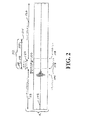
図2A及び2Bはターゲットセグメントを削除することでデータの圧縮をおこなう概念を描いた概念的な概要説明図であり、一方、図2Cと図2Dは、ターゲットセグメントを繰返すことでデータの拡張をおこなう概念を描いた概念的な概要説明図である。実際には、データの圧縮処理とデータの拡張処理は、1つ以上のバッファメモリ内のデータに適用され、このデータはオーディオ信号を示すサンプル値となる。 2A and 2B are conceptual outline explanatory diagrams depicting the concept of compressing data by deleting a target segment, while FIGS. 2C and 2D perform data expansion by repeating the target segment. It is a conceptual outline explanatory drawing depicting the concept. Actually, the data compression process and the data expansion process are applied to data in one or more buffer memories, and this data becomes a sample value indicating an audio signal.
図2Aから2Dの特定された領域は、信号のトランジエントの結果ポストマスキングされる基準を満足しているとはいえ、図2Aから2Dの例に内在する原理は、上記の他の3つを含む他のサイコアコースティックな基準を満足する領域を特定する。 Although the identified regions of FIGS. 2A-2D satisfy the criteria that are post-masked as a result of signal transients, the underlying principles in the examples of FIGS. 2A-2D are the other three above. Identify areas that meet other psychoacoustic criteria, including:
図2Aを参照すると、データ圧縮が描かれており、オーディオ102は、「特定された領域」を構成するサイコアコースティックにポストマスキングされた領域106の一部となるトランジエント104を有する。このオーディオは分析され、特定された領域106内でスプライスポイント108が選択される。図3A及び図3Bに関連してさらに以下に説明するように、オーディオがバッファ内のブロックで表されている場合、このブロック内に、最小の又は最も早いスプライスポイントの位置(すなわち、データがサンプルで表される場合、それは少ないサンプル又はインデックス番号を有する)と、最大の又は最も遅いスプライスポイントの位置(すなわち、データがサンプルで表わされる場合、それは大きいサンプル又はインデックス番号を有する)が存在する。スプライスポイントの位置は、最小スプライスポイント位置から最大スプライス位置間での可能なスプライスポイント位置の範囲内で選択され、ほとんどの場合、ターゲットセグメントの大きさを最大にするために、スプライスポイントを、最小又は最も早いスプライスポイント位置にすることが望ましいのではあるが、スプライスポイントの位置は決定的なものではない。スプライスポイントの位置の初期値は、特定された領域の開始から(例えば、5msecなどの)短時間経過した時を採用することができる。もっと最適なスプライスポイントを提供する他の方法を以下に記載する。
Referring to FIG. 2A, data compression is depicted, and the audio 102 has a transient 104 that becomes part of a psychoacoustic post-masked region 106 that constitutes a “identified region”. This audio is analyzed and a
オーディオの分析を続け、エンドポイント110が選択される。1つの代案として、この分析には、スプライスポイント108から(大きなサンプル又はインデックス番号に向かって)最大処理ポイントの位置115までの領域112での自己相関が含まれる。実際には、最大エンドポイントの位置は、最大処理ポイントより、以下に詳しく説明するように、クロスフェード時間の半分に等しい時間(または、サンプル数の半分の時間)だけ、早い(少ないサンプル又はインデックス番号を有する)。さらに、以下に詳しく説明するように、自己相関の処理は最小エンドポイントの位置116と最大エンドポイントの位置114との間で、相関の最大を探し出すこと、及び、時間領域の相関又は時間領域の相関と位相の相関の両方を採用することを必要とする。最大と最小のエンドポイント位置を決定する方法を以下に示す。時間圧縮のため自己相関により決定されたエンドポイント110はスプライスポイント108のあとに続く時となる(すなわち、データがサンプルで表される場合、それは大きいサンプル又はインデックス番号を有する)。このスプライスポイント108はスプライスポイントを導くオーディオのリーディングセグメント118を定義する(すなわち、データがサンプルで表される場合、それはスプライスポイントより少ないサンプル数又は指数を有する)。エンドポイント110はエンドポイントの後に続くトレイリングセグメント120を定義する(すなわち、データがサンプルで表される場合、それはエンドポイントより大きいサンプル数又は指数を有する)。スプライスポイント108とエンドポイント110はオーディオのセグメントの終了点つまりターゲットセグメント122を定義する。
The audio analysis continues and endpoint 110 is selected. As one alternative, this analysis includes autocorrelation in
データ圧縮のために、ターゲットセグメントは削除され、図2Bに示すようにリーディングセグメントが、好ましくはクロスフェードの技法を用い、スプライスポイントにおいてトレイリングセグメントと突合せ又は重ね合わせて接合され(図示せず)、このスプライスポイントは特定された領域106内にとどまる。このように、クロスフェードされたスプライス(接合)「ポイント」は接合「領域」として特徴づけられる。接合するアーティファクトの成分は、原理的にクロスフェード内に残り、それは、特定された領域106内にあり、データ圧縮の可聴性を最小限にする。図2Bでは、圧縮されたデータは参照番号102’で示されている。 For data compression, the target segment is deleted and the leading segment is joined to the trailing segment at the splice point, as shown in FIG. 2B, preferably using a cross-fade technique (not shown). This splice point remains within the specified area 106. Thus, a crossfade splice “joint” is characterized as a joint “region”. The joining artifact component remains in principle in the crossfade, which is in the identified region 106, minimizing the audibility of data compression. In FIG. 2B, the compressed data is indicated by reference numeral 102 '.
各図面を通して、同じ参照番号は同様の要素に適用されるとともに、プライムマークのついた参照番号は関連するが修正された要素に用いられる。 Throughout the drawings, the same reference numbers apply to similar elements, and the primed reference numbers are used for related but modified elements.
図2Cを参照すると、データ拡張が描かれているが、オーディオ124は、「特定された領域」を構成するサイコアコースティックにポストマスキングされた領域128の一部となるトランジエント126を有する。データ拡張の場合は、このオーディオは分析され、スプライスポイント130もまた特定された領域128内で選択される。さらに以下に説明するように、オーディオがバッファ内のブロックで表されている場合、このブロック内に、最小のスプライスポイントの位置と、最大のスプライスポイントの位置とが存在する。オーディオは、エンドポイントを突き止めるために、スプライスポイントから前方向(もし、データがサンプルで表される場合、大きいサンプル番号又はインデックス番号の方向)と後ろ方向(もし、データがサンプルで表される場合、小さいサンプル番号又はインデックス番号の方向)の両方向に分析される。前方向と後ろ方向の検索は、最もデータが見つかる可能性の高いスプライスポイントの前と、繰返すのに適当なスプライスポイントの後ろに、データを見つけるために行われる。もっと具体的には、前方向の検索は、スプライスポイント130から最初の最大処理ポイントの位置132までおこなわれ、後ろ方向の検索は、スプライスポイント130から後ろ方向に第二の最大処理ポイントの位置134までおこなわれる。この2つの最大処理の位置は、必ずしもそうでなくてもよいが、スプライスポイント130から同じ数のサンプル数分だけ離れたところにしておけばよい。以下に詳しく説明するように、スプライスポイントから最大検索ポイントの位置までと最大エンドポイントの位置までの二つの信号セグメントは、おのおの、最大の相関を探し出すために自己相関が算出される。自己相関は、時間領域の相関を採用しても良いし、時間領域の相関と位相の相関の両方を採用しても良い。実際には、以下に説明するように、最大エンドポイント位置135は、第二の最大処理ポイントの位置134より、クロスフェード時間の半分に等しい時間だけ(あるいは、等価なサンプル数の時間だけ)遅い(大きいサンプル又はインデックス番号を持つ)。
Referring to FIG. 2C, although the data extension is depicted, the audio 124 has a transient 126 that becomes part of the psychoacoustic
逆に、図2Aと2Bのデータ圧縮の場合では、自己相関により定められるエンドポイント136は、スプライスポイント130に先立つ時点にある(すなわち、オーディオがサンプルで表される場合、小さいサンプル又はインデックス番号を有する)。スプライスポイント130は、スプライスポイントを導くオーディオのリーディングセグメント138を定義する(すなわち、オーディオがサンプルで表される場合、スプライスポイントより小さいサンプル数又は指数を有する)。エンドポイント136はエンドポイントの後に続くトレイリングセグメント140を定義する(すなわち、オーディオがサンプルで表される場合、スプライスポイントより大きいサンプル数又は指数を有する)。スプライスポイント130とエンドポイント136はオーディオのセグメントの終了点つまりターゲットセグメント142を定義する。このように、スプライスポイント、エンドポイント、リーディングセグメント、トレイリングセグメント、およびターゲットセグメントの定義は、データ圧縮及びデータ拡張の場合と同じである。しかし、データ拡張の場合は、ターゲットセグメントはリーディングセグメントとトレイリングセグメント(それは繰返されるので)の両方の一部となり、データ圧縮の場合はターゲットセグメントハそのどちらにも存在しない。
Conversely, in the case of data compression in FIGS. 2A and 2B, the
図2Dでは、リーディングセグメントは、好ましくはクロスフェード(図示されていない)を用いて、スプライスポイントでターゲットセグメントと接合され、出来あがったオーディオ124’において、ターゲットセグメントを繰返させる。データ拡張の場合は、エンドポイント136は、元のオーディオの特定された領域128の中になければならない(このようにして、元のオーディオ内のすべてのターゲットセグメントは、特定された領域内に置かれる)。ターゲットセグメント(リーディングセグメントの一部となる)の最初の演奏142’とスプライスポイント130はマスクされた領域128内にとどまる。ターゲットセグメント(トレイリングセグメントの一部となる)の2番目の演奏は、スプライスポイント130の後にあり、必ずしもそうでなくても良いが、マスクされた領域128の外まで広げることも可能である。しかし、ターゲットセグメントは元のオーディオと時間を拡張したオーディオの両方にあるトレイリングセグメントとつながっているため、このようにマスクされた領域の外へ広げることはオーディオには何ら影響しない。
In FIG. 2D, the leading segment is joined to the target segment at a splice point, preferably using a crossfade (not shown), and the target segment is repeated in the resulting audio 124 '. For data extension, the
圧縮の場合は、トランジエントを削除しないようにするため、拡張の場合は、トランジエントを繰返さないようにするため、ターゲットセグメントにはトランジエントを含まないことが望ましい。従って、スプライスポイント及びエンドポイントは、両方ともトランジエントより早い(すなわち、オーディオがサンプルで表される場合、小さいサンプル又はインデックス番号を有する)か、あるいは遅く(すなわち、オーディオがサンプルで表される場合、大きいサンプル又はインデックス番号を有する)するというように、両方ともトランジエントに対して同じ側に存在させるべきである。 In the case of compression, in order not to delete the transient, in the case of expansion, in order not to repeat the transient, it is desirable that the target segment does not include the transient. Thus, the splice point and end point are both earlier than the transient (ie, if audio is represented in samples, it has a smaller sample or index number) or later (ie, if audio is represented in samples). Both should be on the same side with respect to the transient.
本発明の他の形態では、クロスフェードを選択しオーディオ信号に応じてクロスフェードの形と継続時間を変化させることにより、スプライスの可聴性をさらに減少させることが可能となる。さらに詳細なクロスフェードは図10とその説明と共に以下に示す。実際には、以下に説明するように、クロスフェード時間はスプライスポイントとエンドポイントの極端な位置決めに多少の影響を与える。 In another form of the invention, the audibility of the splice can be further reduced by selecting a crossfade and changing the shape and duration of the crossfade in accordance with the audio signal. A more detailed crossfade is shown below with FIG. 10 and its description. In practice, as described below, the crossfade time has some effect on the extreme positioning of the splice point and end point.
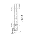
図3Aと3Bは圧縮のため(図3A)と、拡張のため(図3B)の入力オーディオを表すサンプルのブロックの中に最小及び最大のスプライスポイントの位置を決める例を表す。最小(最も早い)スプライスポイントの位置は、最大(最も遅い)スプライスポイントの位置より小さいサンプル又はインデックス番号を有する。スプライスポイントの最小及び最大は、データ圧縮とデータ拡張におけるブロックの終端に関してスプライスに用いられるクロスフェードの長さと相関計算領域の最大長さに、さまざまに関係する。相関計算領域の最大長さの決定について図4とともに詳しく説明する。この相関計算領域は、時間尺度を圧縮するため、エンドポイントを特定するための自己相関計算に用いられ、スプライスポイントの後に来るオーディオデータの領域である。時間尺度を拡張するために、2つの相関計算領域があり、これらは、必ずしもそうしなければならないということではないが、同じ長さで1つはスプライスポイントの前に、もう1つはスプライスポイントの後ろにすることとしても良い。これらは、自己相関計算処理により適当なエンドポイントを決定するために用いられる。 FIGS. 3A and 3B show examples of determining the positions of the minimum and maximum splice points in a block of samples representing input audio for compression (FIG. 3A) and for expansion (FIG. 3B). The position of the smallest (earliest) splice point has a sample or index number that is smaller than the position of the largest (latest) splice point. The minimum and maximum splice points are related variously to the length of the crossfade used for splicing and the maximum length of the correlation calculation area with respect to the end of the block in data compression and data expansion. The determination of the maximum length of the correlation calculation area will be described in detail with reference to FIG. This correlation calculation area is used for autocorrelation calculation for specifying an end point in order to compress the time scale, and is an area of audio data that comes after the splice point. To extend the time scale, there are two correlation calculation areas, which are not necessarily the same, but of the same length, one before the splice point and the other as the splice point. It is also good to be behind. These are used to determine appropriate endpoints by the autocorrelation calculation process.
オーディオデータの各ブロックには、最小スプライスポイント位置と最大スプライスポイント位置とがある。図3Aに示すように、ブロックの終端に対する最小スプライスポイント位置は、圧縮の場合は最も早い時間を表しており、スプライスポイント近傍のオーディオデータは終点付近でクロスフェードされるので、クロスフェードの長さの半分に制限される。同様に、時間尺度の圧縮のために、ブロックの終端に対する最大スプライスポイント位置は、圧縮の場合は最も遅い時間を表しており、クロスフェードの最大長さに制限される(最大エンドポイントの位置は、クロスフェードの長さの半分だけ最大処理長さより「早い」位置である)。 Each block of audio data has a minimum splice point position and a maximum splice point position. As shown in FIG. 3A, the minimum splice point position relative to the end of the block represents the earliest time in the case of compression, and the audio data near the splice point is crossfaded near the end point, so the length of the crossfade Is limited to half. Similarly, for time scale compression, the maximum splice point position relative to the end of the block represents the slowest time in the case of compression and is limited to the maximum length of the crossfade (the maximum endpoint position is , Half the length of the crossfade is “faster” than the maximum processing length).
図3Bは時間尺度拡張のための最大及び最小スプライスポイント位置決定の概要を示す。ブロックの終端に対する最小スプライスポイント位置は、時間尺度拡張について最も早い時間を表しており、時間尺度縮小のための最大スプライスポイントの決定の場合と同様に、相関計算領域の最大長さに関係する(最小エンドポイントの位置は、最大相関計算処理長さの終点よりクロスフェードの長さの半分だけ「遅い」位置である)。ブロックの終端に対する最大スプライスポイント位置は、時間尺度拡張について最も遅い時間を表しており、相関計算領域の最大長さだけに関係する。これは、時間尺度拡張のためのスプライスポイントに続くデータは相関計算処理にのみ用いられ、エンドポイントは最大スプライスポイントの後に位置しないからである。 FIG. 3B shows an overview of determining the maximum and minimum splice points for time scale extension. The minimum splice point location relative to the end of the block represents the earliest time for the time scale extension and is related to the maximum length of the correlation calculation area, as in the determination of the maximum splice point for time scale reduction ( The position of the minimum end point is a position “slower” by half the length of the crossfade than the end point of the maximum correlation calculation processing length). The maximum splice point position relative to the end of the block represents the latest time for the time scale extension and is only related to the maximum length of the correlation calculation region. This is because the data following the splice point for time scale extension is used only for the correlation calculation process, and the end point is not located after the maximum splice point.
図3Aと3Bは入力データのブロックについて描かれているが、以下に説明するように、オーディトリーイベントを含んで別に処理される入力データの小部分(つまり、連続するサンプルの集合)に関する最大及び最小エンドポイントの決定に、同様の原理が適用される。 Although FIGS. 3A and 3B are drawn for blocks of input data, as described below, the maximum and minimum for a small portion of input data (ie, a set of consecutive samples) that are processed separately, including audity events, and Similar principles apply to determining the minimum endpoint.
図4に示すように、時間尺度の圧縮の場合は、相関計算処理のための領域はスプライスポイントの後ろに位置する。スプライスポイントと最大処理ポイント位置は相関計算処理領域を定義する。図4に示されたスプライスポイントと最大処理ポイントの位置は恣意的な例である。最小エンドポイント位置は、エンドポイントが位置するスプライスポイント後部の最小サンプル又はインデックス値を示す。同様に、最大エンドポイント位置は、エンドポイントが位置するスプライスポイント後部の最大サンプル又はインデックス値を示す。最大エンドポイント位置は、最大処理ポイント位置よりクロスフェード長さの半分だけ「早い」位置となる。いったんスプライスポイントが選定されると、最小と最大エンドポイント位置は、ターゲットセグメントに使われるデータの量を制御し、初期値(使用可能な値は、各々7.5と25msecである)が与えられる。代案として、最小と最大エンドポイント位置は、オーディオの内容及び/又は時間尺度の要求量に応じてダイナミックに変更するために可変としても良い(最小エンドポイントは時間尺の割合に基づき変化させても良い)。例えば、その支配的な周波数が50Hzで、44.1kHzでサンプルされている信号に対して、オーディオ波形の1周期は約882サンプルとなる(又は20msecとなる)。このことは最大エンドポイントの位置は、オーディオデータの少なくとも1周期を含むのに十分な長さのターゲットセグメントという結果にすべきであるということを示している。どんな場合でも、最大処理ポイントは処理ブロックの終点より遅くはならない(この例では、4096サンプル、または、以下に説明するようにオーディトリーイベントを考慮に入れれば、オーディトリーイベントの終点より遅くはならない)。同様に、もし最小エンドポイントの位置がスプライスポイントの後7.5msecの位置に選ばれ、処理されているオーディオが最小エンドポイントの位置の近くにエンドポイントを一般に選択する信号を含んでいるなら、時間尺度の最大パーセンテージは書く入力データブロックの長さに依存する。例えば、入力データブロックのサイズが4096サンプル(又は44.1kHzのサンプルレートで約93msec)であるとすると、最小エンドポイント位置が選ばれれば、7.5msecの最小ターゲットセグメントの長さは、7.5/93=8%の最大時間尺度比率という結果となる。時間尺度縮小のための最小エンドポイントの位置を、7%の変化以下の比率にするため、7.5msecにすることが可能となり、
最小エンドポイントの位置=((時間尺度比率‐1.0)*ブロックサイズ)
と等しくなる。
As shown in FIG. 4, in the case of time scale compression, the area for the correlation calculation process is located behind the splice point. The splice point and the maximum processing point position define the correlation calculation processing area. The positions of the splice points and maximum processing points shown in FIG. 4 are arbitrary examples. The minimum endpoint position indicates the minimum sample or index value behind the splice point where the endpoint is located. Similarly, the maximum endpoint position indicates the maximum sample or index value behind the splice point where the endpoint is located. The maximum end point position is “earlier” by half the crossfade length than the maximum processing point position. Once a splice point has been selected, the minimum and maximum endpoint positions control the amount of data used for the target segment and are given initial values (available values are 7.5 and 25 msec, respectively). . Alternatively, the minimum and maximum endpoint positions may be variable to dynamically change depending on the audio content and / or time scale requirements (the minimum endpoint may be varied based on the time scale ratio). good). For example, for a signal whose dominant frequency is 50 Hz and sampled at 44.1 kHz, one period of the audio waveform is about 882 samples (or 20 msec). This indicates that the location of the maximum endpoint should result in a target segment that is long enough to contain at least one period of audio data. In any case, the maximum processing point will not be later than the end point of the processing block (in this example, 4096 samples, or after the audity event as described below, will not be later than the end point of the audity event) ). Similarly, if the minimum endpoint location is chosen 7.5msec after the splice point and the audio being processed contains a signal that generally selects the endpoint near the minimum endpoint location, The maximum percentage of the time scale depends on the length of the input data block being written. For example, if the size of the input data block is 4096 samples (or about 93 msec at a sample rate of 44.1 kHz), the minimum target segment length of 7.5 msec is 7. The result is a maximum time scale ratio of 5/93 = 8%. In order to set the position of the minimum endpoint for time scale reduction to a ratio of 7% change or less, it can be set to 7.5 msec.
Minimum endpoint location = ((time scale ratio-1.0) * block size)
Is equal to
ここで、時間尺度圧縮のためには時間尺度比率>1.0であり(1.10=10%再生時間比率増大)、そして44.1kHzにて目下ブロックサイズは4096サンプルとなる。これらの例は、最小及び最大エンドポイントの位置を、オーディオの内容及び時間尺度の比率の要求量に応じて変化させることの利点を示している。いずれにせよ、最小エンドポイントは、サーチ領域の極端な制限ほど大きくすべきでなく、最大エンドポイントに近づくべきでもない。 Here, for time scale compression, the time scale ratio is> 1.0 (1.10 = 10% increase in playback time ratio), and at 44.1 kHz, the current block size is 4096 samples. These examples show the benefit of changing the location of the minimum and maximum endpoints depending on the audio content and the time scale ratio requirements. In any case, the minimum endpoint should not be as large as the extreme limits of the search area and should not approach the maximum endpoint.
本発明の更なる特徴は、マスキングや非可聴性に頼る必要を少なくするためスプライスポイントとエンドポイントでの信号波形を一致させる比較技術を用いることも可能である。本発明の更なる特徴である一致技術は、接合点で繋ぐ波形の振幅と位相の両方が一致する点を求めるものである。これは先に述べた相関計算を必要とし、これも本発明の1つの特徴である。相関計算は周波数に対する耳の感度の変化による補正を含んでも良い。 A further feature of the present invention is the ability to use a comparison technique that matches the signal waveforms at the splice point and endpoint to reduce the need to rely on masking and inaudibility. The matching technique, which is a further feature of the present invention, finds a point where both the amplitude and phase of the waveform connected at the junction point match. This requires the correlation calculation described above, which is also a feature of the present invention. The correlation calculation may include correction due to changes in ear sensitivity to frequency.
図2A‐2Dと共に説明したように本発明の特徴として採用されたデータの圧縮或いは拡張では、オーディオの一部を削除したり繰返したりする。最初に説明した案では、クロスフェードの長さ、又は、トランジエント及び/又は他の信号条件を考慮したような信号要素から定めたスライスポイントの位置の要求距離を基礎とする、一般的な、あらかじめ定められたシステムパラメータを用いてスプライスポイントの位置が選定される。ある程度任意なスプライスポイントに対してさらに詳細なオーディオの分析(例えば相関計算)がおこなわれエンドポイントを決める。 As described in conjunction with FIGS. 2A-2D, in the data compression or expansion employed as a feature of the present invention, a part of the audio is deleted or repeated. In the first described scheme, a general, based on the required distance of the position of the slice point determined from the signal elements such as considering the length of the crossfade or transient and / or other signal conditions, The position of the splice point is selected using predetermined system parameters. A more detailed audio analysis (for example, correlation calculation) is performed on a certain arbitrary splice point to determine an end point.
2番目の案では、スプライスポイントとエンドポイントの位置はもっと信号に依存した方法で選定される。一連の仮に定めたスプライスポイント位置周辺の窓にはめられたデータは仮に定めた対応するエンドポイント位置を選定するために、相関計算処理領域のデータに対して相関計算がなされる。すべての仮に定めたスプライスポイント位置の中で最も強い相関関係を示した仮のスプライスポイント位置が最終のスプライスポイントとして選定され、仮に定めたエンドポイントは実質的に最も強い相関を示しタ位置に決められる。原則として、仮に定めたスプライスポイント間のスペースは、1サンプル分としたが、処理の複雑さを軽減するために仮に定めたスプライスポイントはもっと広く間隔を空けても良い。以下に記載するように、クロスフェード領域の幅は仮に定めたスプライスポイントのために適当に広げておく。スプライスポイントとエンドポイントの位置を選ぶという方法は、データ圧縮及びデータ拡張の両方の処理に適用される。このスプライスポイントとエンドポイントの位置を選ぶという代案は、オーディトリーシーンアナリシスに採用される本発明の特徴に関連して、以下にさらに詳細に説明するが、サイコアコースティックアナリシスを採用する最初に説明した本発明の実施例に、この代案を採用しても良い。
In the second scheme, the positions of splice points and endpoints are selected in a more signal dependent manner. Correlation calculation is performed on the data in the correlation calculation processing area in order to select the corresponding end point position temporarily determined for the data set in the window around the series of temporarily determined splice point positions. The provisional splice point position that showed the strongest correlation among all the provisional splice point positions was selected as the final splice point, and the provisional end point was determined to be the data position that showed the substantially strongest correlation. It is done. In principle, the space between the temporarily determined splice points is one sample. However, the temporarily determined splice points may be more widely spaced in order to reduce processing complexity. As described below, the width of the crossfade region is appropriately widened for a temporarily determined splice point. The method of selecting the positions of splice points and endpoints applies to both data compression and data expansion processes. This alternative of selecting splice point and end point locations will be described in more detail below in connection with the features of the present invention employed in the auditory scene analysis, but was first described in employing psychoacoustic analysis. This alternative may be employed in embodiments of the present invention.
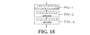
サイコアコースティックアナリシスの実施例
サイコアコースティックアナリシスを伴う本発明に係る単一又は多数チャンネルのタイムスケーリング及び/又はピッチスケーリング処理を説明するフローチャートを図5に示す。サイコアコースティックアナリシスとオーディトリーシーンアナリシスの両方を伴う本発明に係る単一又は多数チャンネルのタイムスケーリング及び/又はピッチスケーリング処理を説明するフローチャートを図17に示し、以下に説明する。本発明の他の形態は、図5と図17の処理の変形或いは一部をなす。この処理は、実時間のピッチスケーリングと実時間でないピッチ及びタイムスケーリングを実施するために用いることができる。異なる比率で再生するためには入力オーディオ信号をバッファしておかなければならず、バッファのアンダーフローやオーバーフローをもたらすため、待ち時間の少ないタイムスケーリング処理は実時間の場面では効率的に運用できない。すなわち、バッファは受け取った入力信号とは異なる比率では空になるのである。
Example of Psychoacoustic Analysis FIG. 5 shows a flowchart illustrating a single or multiple channel time scaling and / or pitch scaling process according to the present invention with psychoacoustic analysis. A flow chart illustrating single or multiple channel time scaling and / or pitch scaling processing according to the present invention with both psychoacoustic analysis and audition scene analysis is shown in FIG. 17 and described below. Another embodiment of the present invention is a modification or part of the processing of FIGS. This process can be used to implement real-time pitch scaling and non-real-time pitch and time scaling. In order to reproduce at different ratios, the input audio signal must be buffered, which causes buffer underflow and overflow. Therefore, the time scaling process with low waiting time cannot be operated efficiently in real time. That is, the buffer is emptied at a different rate than the received input signal.
入力信号202(図5)
図5において、最初のステップである決定ステップ(「入力データ?」)は、ディジタル化された入力データはデータ圧縮或いはデータ拡張処理が可能かどうかを決定する。データの発信源は、例えば、リアルタイムに入力バッファに蓄えることのできる、コンピュータのファイルやひとかたまりの入力データとすることができる。もしデータが有効であるならば、同時に発生したセグメントを表すN個の同期化されたひとかたまりのサンプルデータは、ステップ204(「各チャンネルのサンプルを入手」)で、データ圧縮又はデータ拡張処理のために入力チャンネルごとに1つのブロックとしてまとめられる(チャンネル数は1以上である)。処理に使われる入力データのサンプル数Nは、合理的なサンプル数に固定され、その数により入力データをブロックに分割する。原則として、処理するオーディオはディジタルでもアナログでも良く、ブロックに分割されている必要はない。
Input signal 202 (FIG. 5)
In FIG. 5, the determination step (“input data?”), Which is the first step, determines whether the digitized input data can be subjected to data compression or data expansion processing. The source of data can be, for example, a computer file or a batch of input data that can be stored in the input buffer in real time. If the data is valid, N synchronized batches of sample data representing simultaneously occurring segments are obtained in step 204 ("Get Samples for Each Channel") for data compression or data expansion processing. Are grouped as one block for each input channel (the number of channels is one or more). The number N of input data samples used for processing is fixed to a reasonable number of samples, and the input data is divided into blocks according to the number. In principle, the audio to be processed may be digital or analog and need not be divided into blocks.
図5は、各オーディオチャンネルへの入力データが、サンプリングレートが44.1kHzで約93msecのオーディオ入力に該当するような、4096サンプルのブロックにデータ圧縮又はデータ拡張される本発明の実用的な実施例に関連して論じるものである。本発明の形態はこのような実用的な実施例に限定されないことは了解されよう。上述のとおり、本発明の種々の形態において本質的に、オーディオをサンプルブロックにしておくことを要求しないし、固定長さのブロックにして提供することも要求しない。しかし、複雑さを最小限にするため、4096サンプルに固定した長さのブロック(または、2つの番号を持つサンプルの他の能力)は主として3つの理由により有益である。1番目は、実時間での処理を行うアプリケーションの適用が可能なように十分短い待ち時間を提供することが可能なことである。2番目は、高速フーリエ変換(FFT)分析に有効な、サンプルの2つの番号の能力である。3番目は、サイコアコースティックな入力信号の有効な分析を実行するために適当な大きさの窓枠サイズを提供することである。 FIG. 5 shows a practical implementation of the invention in which the input data to each audio channel is data compressed or expanded to 4096 sample blocks such that the sampling rate is 44.1 kHz and corresponds to an audio input of about 93 msec. It will be discussed in connection with examples. It will be appreciated that aspects of the present invention are not limited to such practical examples. As noted above, the various aspects of the present invention do not essentially require the audio to be sample blocks, nor does it require it to be provided as fixed length blocks. However, to minimize complexity, a block of length fixed to 4096 samples (or other capabilities of samples with two numbers) is beneficial mainly for three reasons. First, it is possible to provide a sufficiently short waiting time so that an application that performs processing in real time can be applied. The second is the ability of the two numbers of samples to be useful for fast Fourier transform (FFT) analysis. The third is to provide an appropriate window frame size to perform an effective analysis of the psychoacoustic input signal.
以下の議論において、入力信号は、振幅値が[−1,+1]のレンジを持つデータであると仮定する。
In the following discussion, it is assumed that the input signal is data having an amplitude value in the range of [-1, +1].
サイコアコースティックアナリシス206(図5)
以下の入力データブロックは、サイコアコースティックアナリシス206(「各入力データブロックにおけるサイコアコースティックアナリシス処理」)は各チャンネルへの入力データブロックに対して実行される。多数チャンネルの場合は、サイコアコースティックアナリシス206とそれに付随するステップはすべてのチャンネルに対して並列に処理するか、または、チャンネルからチャンネルへと(各チャンネルのデータと各々の分析に適当な記憶装置を準備することにより)順次処理することが可能である。並列処理は非常に高い処理能力を必要とするが、実時間処理のアプリケーションには並列処理が好ましい。図5の説明はチャンネルは並列に処理することを仮定する。
Psychoacoustic analysis 206 (Fig. 5)
For the following input data blocks, psychoacoustic analysis 206 ("Psychoacoustic analysis processing in each input data block") is performed on the input data blocks to each channel. In the case of multiple channels,
ステップ206の詳細は図6に示されている。アナリシス206では、サイコアコースティックな基準を満足する各チャンネルにデータブロック中に1以上の領域を定め(または、ある信号条件の下ではブロック中にこのような領域を定めない)、各定められた領域内に潜在的なあるいは一時的なスプライスポイントの1を決定する。チャンネルが一つしかない場合は、次のステップ210(「共通スプライスポイントの選択」)が省略され、ステップ206で決定された一時的なスプライスポイントの1つから選んだスプライスポイントの位置を用いることができる(基準の上下関係に従って「最適」な領域が選ばれることが好ましい)。多数チャンネルの場合は、ステップ210にて、定められた領域の再検査が行われ、共通に重なり合う領域を特定し、このような共通に重なり合った領域から最適なスプライスポイントを選ぶ。ここで、素プライスポイントは、必ずしもそうでなくてもよいが、ステップ206のサイコアコースティックアナリシスにおいて定めた一時的なスプライスポイントであってもよい。
Details of
オーディオのタイム及び/又はピッチスケーリングにおいて可聴なアーティファクトを最小限にするためのサイコアコースティックアナリシスの採用が、本発明の1つの特徴である。サイコアコースティックアナリシスには、上述の4つの基準、又は、他の、波形の接合から発生したり、タイム及び/又はピッチスケーリングを実行するときに発生したりするアーティファクトを減少又は最小限にするオーディオのセグメントを特定する、他のサイコアコースティックアな基準から1つ以上を適用することが含まれる。 The adoption of psychoacoustic analysis to minimize audible artifacts in audio time and / or pitch scaling is a feature of the present invention. Psychoacoustic analysis includes the above four criteria, or other audio audio that reduces or minimizes artifacts that arise from splicing of waveforms or when performing time and / or pitch scaling. Applying one or more from other psychoacoustic criteria that identify the segment is included.
図5の処理では、ブロック内にサイコアコースティックに特定された多数の領域があり、各々が暫定的に定めたスプライスポイントを有する。それでも、1つの実施例では、単一チャンネルの場合、各入力データブロック中にサイコアコースティックに特定された1つの領域の最大値がデータ圧縮又は拡張のためのデータとして選択されることが、また、多数チャンネルの場合、入力データの同時性のある各ブロック(各チャンネルへの1つのブロック)がデータ圧縮又は拡張のために選択されることが好ましい。多数の特定された領域又は多数の特定された領域の重複部分がブロックや入力部分にそれぞれあるとき、サイコアコースティックには、(たとえば、ここで述べた階層的に)「最良の」特定された領域又は、特定された領域の重複部分が選択されることが好ましい。 In the process of FIG. 5, there are a large number of areas identified as psychoacoustics in the block, and each has a provisional splice point. Nevertheless, in one embodiment, for a single channel, the maximum value of one region specified in psychoacoustic during each input data block is selected as data for data compression or expansion, For multiple channels, each simultaneous block of input data (one block to each channel) is preferably selected for data compression or expansion. Psychoacoustics (for example, hierarchically as described here) “best” identified regions when there are multiple identified regions or overlapping portions of multiple identified regions in the block or input portion, respectively. Or it is preferable that the overlapping part of the specified area | region is selected.
代案として、1以上の特定された領域、又は各ブロック内に又は、同時に入力されたブロックのセット内に特定された領域の1以上の重複部分は、各々、処理のために選択される。この場合、選択された領域はサイコアコースティックに(たとえば、ここで述べた階層的に)最適なものであることが望ましい。あるいは、特定されたイベントが選択可能としてもよい。 Alternatively, one or more identified regions, or one or more overlapping portions of regions identified within each block or set of simultaneously input blocks, are each selected for processing. In this case, it is desirable that the selected region is optimal for psychoacoustics (eg, hierarchically as described herein). Alternatively, the identified event may be selectable.
各特定された領域に暫定的なスプライスポイントを置く代わりに、単一チャンネルの場合は、スプライスポイント(この場合は「一時的」ではなく実際のスプライスポイント)を、処理のため特定された領域が選定された後、その特定された領域に置いてもよい。多数チャンネルの場合は、暫定的なスプライスポイントは、それらが重複していることが確認された後にのみ、特定された領域に置くことが可能である。 Instead of placing a temporary splice point in each identified area, in the case of a single channel, the splice point (in this case the actual splice point rather than “temporary”) is replaced by the area identified for processing. After being selected, it may be placed in the specified area. In the case of multiple channels, provisional splice points can be placed in a specified area only after confirming that they are overlapping.
多数チャンネルがあるときは、共通のスプライスポイントは、一般的に各々のチャンネルの暫定的に各スプライスポイントとは違っているので、重複する領域に共通するスプライスポイントを選択すべきだから、多数チャンネルがあるときは、原則として暫定的なスプライスポイントの特定は必要でない。しかし、暫定的なスプライスポイントを特定しておけば、暫定的なスプライスポイント(これは実際のスプライスポイントになる)を要求する単一チャンネルとでも、暫定的なスプライスポイントを無視する多数チャンネルとでも、操作が可能となるので、詳細実行時には暫定的なスプライスポイントの特定は有効である。 When there are multiple channels, the common splice point is generally different from each splice point of each channel, so you should select a common splice point for the overlapping area, so In some cases, it is not necessary to specify a provisional splice point in principle. However, once the temporary splice point is identified, it can be a single channel that requires a temporary splice point (which becomes the actual splice point) or a large number of channels that ignore the temporary splice point. Since the operation becomes possible, the provisional splice point specification is effective at the time of detailed execution.
図6は、図5におけるサイコアコースティックアナリシス処理206の動作のフローチャートである。サイコアコースティックアナリシス処理206は5つの概略的なサブステップにより成り立っている。最初の4つはサイコアコースティック基準による分析のサブステップで、最初のサブステップ又は最初の基準を満足するオーディオ領域は、最も非可聴又は最小可聴領域内にスプライス(又は他のタイム又はピッチシフティング処理)がある可能性が高く、それに続く基準は、非可聴又は最小可聴領域内にスプライスがある可能性は少なくなっている。
FIG. 6 is a flowchart of the operation of the
サイコアコースティック基準による分析の各サブステップは入力データブロックの64分の1のサイズを持ったサイコアコースティックサブブロックを採用する。この例では、サイコアコースティックサブブロックは、図8に示すように1.5msec(又は44.1kHzで64サンプル)である。サイコアコースティックサブブロックの大きさは必ずしも1.5msecである必要はないが、これは、実時間処理からの要求(より大きなサブブロックの大きさは、より小さなサイコアコースティック処理で済む)とサイコアコースティック基準を満足するセグメントの分解能(より小さなサブブロックはこのようなセグメントの位置により詳細な情報をもたらす)との二律背反をもたらすため、この値は、実際の実施例から決めたものである。一般的に、サイコアコースティックサブブロックの大きさは、サイコアコースティック基準による分析の各タイプと同じ大きさにする必要はないが、実用的な実施例では、実行がしやすいように、同じであることが望ましい。
Each sub-step of the analysis according to the psycho-acoustic criterion employs a psycho-acoustic sub-block with a size of 1/64 of the input data block. In this example, the psychoacoustic sub-block is 1.5 msec (or 64 samples at 44.1 kHz) as shown in FIG. The size of psychoacoustic sub-blocks does not necessarily need to be 1.5 msec, but this is a requirement from real-time processing (larger sub-block sizes require smaller psychoacoustic processing) and psychoacoustic standards This value is determined from the actual implementation because it provides a tradeoff with the resolution of the segment that satisfies (smaller sub-blocks provide more information on the location of such segments). In general, the size of the psychoacoustic sub-block does not have to be the same as each type of analysis according to the psychoacoustic criteria, but in practical embodiments it should be the same for ease of implementation. Is desirable.
トランジエントの検出206−1(図6)
処理206−1は、各チャンネルのデータブロックを分析し、もしあれば、オーディオ信号のトランジエントの位置を決定する。時間的なトランジエントの情報は、マスキングの分析と暫定的なスプライスポイントの位置決定のために用いられる(この例におけるサイコアコースティックアナリシス処理の最後のサブステップ)。先に論じたように、トランジエントは時間的なマスキング(トランジエントが発生した前と後ろの両方でオーディオ情報を隠す)をもたらすことは良く知られている。
Transient detection 206-1 (FIG. 6)
Process 206-1 analyzes the data block for each channel and, if any, determines the location of the transient in the audio signal. Temporal transient information is used for masking analysis and provisional splice point location (the last sub-step of the psychoacoustic analysis process in this example). As discussed above, it is well known that transients provide temporal masking (hiding audio information both before and after the transient occurs).
図7に示されているように、トランジエント検出サブステップ206−1において最初のサブステップ206−1a(「全帯域幅オーディオ入力ハイパスフィルター」)は、入力データブロックにフィルターをかけることになる。入力ブロックデータは、例えば、約8kHZのカットオフ周波数を持った2次元IIRハイパスフィルターにより、ハイパスフィルターがかけられる。フィルターがかけられたデータは元のフィルターがかけられていないデータと共にトランジエント分析に使われる。全帯域幅とハイパスフィルターをかけたデータの両方を使うことは、音楽のような複雑な素材においても、トランジエントを定める能力を高める。「全帯域幅」のデータは、例えば非常に高い周波数や低い周波数に対してフルターをかけることにより、帯域幅を制限することができる。このデータは1以上の異なったカットオフ周波数を持ったフィルターを追加することでハイパスフィルターをかけることができる。信号の高周波トランジエント成分は、低周波成分よりも十分強度の小さい振幅を持つが、依然としてリスナーに聞こえる可能性が高い。入力データにフィルターをかけることは、高周波のトランジエントから独立させ、トランジエントを特定することが容易になる。 As shown in FIG. 7, the first sub-step 206-1a (“Full Bandwidth Audio Input High-Pass Filter”) in the transient detection sub-step 206-1 will filter the input data block. The input block data is subjected to a high pass filter by, for example, a two-dimensional IIR high pass filter having a cutoff frequency of about 8 kHz. The filtered data is used for transient analysis along with the original unfiltered data. Using both full bandwidth and high-pass filtered data increases the ability to define transients even in complex materials such as music. The bandwidth of the “total bandwidth” data can be limited by, for example, filtering a very high frequency or a low frequency. This data can be high pass filtered by adding filters with one or more different cutoff frequencies. The high frequency transient component of the signal has an amplitude that is sufficiently smaller than the low frequency component, but is still likely to be heard by the listener. Filtering the input data is independent of the high frequency transients and makes it easier to identify the transients.
次のサブステップ206−1b(「全帯域幅及びフィルターされたオーディオサブブロックにおける最大絶対値サンプルの位置決め」)において、全帯域幅及びフィルターされた入力ブロックの両方が、全帯域幅及びフィルターされたオーディオのブロックにおける最大絶対値サンプルの位置を決めるため、図8に示すように、約1.5msec(又は44.1kHzで64サンプル)のサブブロックで処理される。 In the next sub-step 206-1b ("Position of maximum absolute samples in full bandwidth and filtered audio sub-block"), both the full bandwidth and the filtered input block are full bandwidth and filtered. To determine the position of the maximum absolute value sample in the audio block, it is processed in sub-blocks of about 1.5 msec (or 64 samples at 44.1 kHz) as shown in FIG.
3番目の、トランジエント検出サブステップ206−1のサブステップ206−1c(「全帯域幅及びフィルターされたピークデータのローパスフィルターによる平準化」)は、サブブロックローパスフィルターの実行、又は64サンプルのサブブロックに含まれる絶対値の最大を平均化する(データ値を時間関数として扱う)。この処理は、絶対値データの最大を平準化し、実際のサブブロックの最大絶対値と比較できるような、入力ブロックにおける平均ピーク値の一般的な目安を与える。 The third, sub-step 206-1c of transient detection sub-step 206-1 ("leveling the whole bandwidth and filtered peak data with a low-pass filter") is the execution of the sub-block low-pass filter, or 64 samples. Averages the maximum absolute value contained in a sub-block (treats the data value as a time function). This process provides a general measure of the average peak value in the input block so that the maximum of the absolute value data can be leveled and compared with the maximum absolute value of the actual sub-block.
3番目の、トランジエント検出サブステップ206−1のサブステップ201−1d(「全帯域幅及びフィルターされた各ブロックの絶対値のピーク値と平準化されたデータとの比較」)は、トランジエントの存在を検出するために、各サブブロックのピークと、それに対応する数の一連の平準化されたピーク値の移動平均値とを比較する。2つの値を比較する方法は多数存在するが、以下でおこなうやり方は、幅広いオーディオ信号の分析による決定が最適に実行できるようなスケールファクターを用いて比較の調整をおこなっている。 The third sub-step 201-1d of the transient detection sub-step 206-1 ("Comparison of the total bandwidth and the peak value of the absolute value of each filtered block with the leveled data") Is detected by comparing the peak of each sub-block with the moving average of a corresponding number of series of leveled peak values. There are many ways to compare two values, but the following approach adjusts the comparison using a scale factor that can be optimally determined by analysis of a wide range of audio signals.
サブステップ206−1e(「スケール化データ>平準化データ?」)での決定では、K番目のサブブロックにおけるピーク値はスケール値で乗算され、平準化計算がなされた、ピーク値の移動平均値と比較される。もし、サブブロックのスケール化されたピーク値が移動平均値よりも大きければ、トランジエントが存在するとのフラグが与えられる。サブブロックないのトランジエントの存在とその位置は続く処理のために記憶される。この作業は、フィルターされないデータとフィルターされたデータの両方になされる。トランジエントが存在するとのフラグが与えられたサブブロック又はトランジエントが存在するとのフラグが与えられた一連の連続したサブブロックはトランジエントの存在と位置を示している。この情報は、例えば、トランジエントによってプレマスキング及びポストマスキングが適用されるところや、トランジエントに対する外乱を避けるために、データの圧縮あるいは拡張は避けるべきところを示すためのような、他の処理にも採用される(例えば、図6のサブステップ310参照)。 In the determination in the sub-step 206-1e (“scaled data> leveled data?”), The peak value in the Kth sub-block is multiplied by the scale value, and the leveled moving average value obtained by leveling calculation is obtained. Compared with If the scaled peak value of the sub-block is greater than the moving average value, a flag indicating that a transient exists is given. The presence and location of transients without sub-blocks are stored for subsequent processing. This work is done for both unfiltered and filtered data. A sub-block flagged as having a transient or a series of consecutive sub-blocks flagged as having a transient indicates the presence and position of the transient. This information can be used in other processes, for example, where pre-masking and post-masking are applied by the transient, or to indicate where data compression or expansion should be avoided to avoid disturbance to the transient. Is also employed (see, for example, sub-step 310 of FIG. 6).
トランジエント検出に続いて、サブステップ206−1f(「トランジエント解消のための修正チェック実施」)にて、サブブロックの64サンプルに対するトランジエントフラグが解消(TRUEからFALSEへのリセット)されるべきかを決定するために、いくつかの修正のためのチェックがおこなわれる。これらのチェックは、間違ったトランジエントの検出を減らすために実施される。最初に、全帯域での又は高周波でのピーク値が最低ピーク値以下に落ちたならば、(ほんの少しの時間的マスキングしか、又はまったく時間的マスキングをもたらさないような低いレベルのトランジエントを削除するために)トランジエントは解消される。2番目に、サブブロックのピークはトランジエントを引き起こすものであるが、トランジエントフラグを引き起こしたであろうような、以前のサブブロックよりそれほど大きくない場合、このサブグロックのトランジエントは解消される。これはトランジエントの位置情報に対する誤りを減らす。各オーディオチャンネルに対し、トランジエントの数とそれらの位置は、後でサイコアコースティックアナリシスのステップで用いるために、記憶される。 Subsequent to transient detection, in sub-step 206-1f ("Perform correction check for transient elimination"), the transient flag for 64 samples in the sub-block should be eliminated (reset from TRUE to FALSE). Several correction checks are made to determine this. These checks are performed to reduce false transient detection. First, if the peak value in the entire band or at high frequencies falls below the minimum peak value, remove low level transients that will result in very little temporal masking or no temporal masking at all. Transients are eliminated). Second, the peak of the sub-block will cause a transient, but if it is not much larger than the previous sub-block, which would have caused the transient flag, the sub-block transient is eliminated. This reduces errors in transient location information. For each audio channel, the number of transients and their positions are stored for later use in psychoacoustic analysis steps.
本発明はここで記述した特定のトランジエント検出に制限されるものではない。他の適当なトランジエント検出方法も採用される。
The present invention is not limited to the specific transient detection described herein. Other suitable transient detection methods are also employed.
可聴閾値分析206−2(図6)
図6を再度参照すると、サイコアコースティックアナリシス処理の2番目のステップ206−2、つまり可聴閾値分析は、十分低い信号強度を持ち、可聴閾値以下であると考えられるオーディオセグメントの位置と継続時間を決定する。上記で論じた通り、これらのオーディオセグメントが対象となる。なぜなら、タイムスケーリング及びピッチシフティングにより誘起されたアーティファクトはほとんどこのような領域内では可聴とならないためである。
Audible threshold analysis 206-2 (FIG. 6)
Referring back to FIG. 6, the second step 206-2 of the psychoacoustic analysis process, ie the audible threshold analysis, determines the position and duration of audio segments that have sufficiently low signal strength and are considered to be below the audible threshold. To do. As discussed above, these audio segments are of interest. This is because the artifacts induced by time scaling and pitch shifting are hardly audible in such areas.
上述の通り、可聴閾値は周波数の関数である(高・低周波数域のものは中間周波数のものより可聴性が低い)。実時間処理のアプリケーションにおける処理を最小限にするために、分析のための可聴閾値モデルは、可聴閾値が一定(最も感度の高い周波数帯域での可聴閾値をすべての周波数に適用する)と仮定してもよい。このような控えめな仮定をすることにより、聴感度曲線を仮定し、処理労力を下げるより前に、入力データに対する周波数に依存する処理を適用することにより要求水準を下げたときに比べて、オペレータにとって再生ボリュームを上げる余裕が大きくなる。 As described above, the audible threshold is a function of frequency (high and low frequency regions are less audible than intermediate frequencies). To minimize processing in real-time processing applications, the audible threshold model for analysis assumes that the audible threshold is constant (the audible threshold in the most sensitive frequency band is applied to all frequencies). May be. By making such a conservative assumption, the operator is assumed to have an auditory sensitivity curve and before the processing effort is reduced, the operator is compared with the case where the requirement level is lowered by applying a frequency-dependent processing to the input data. For this, the margin for raising the playback volume is increased.
可聴閾値分析ステップはフィルターされていないオーディオに適用され、約1.5msecの入力(44.1kHzで64サンプルの入力データ)にも適用され、上述の平準化された移動平均計算を用いる。この計算に続いて、各サブブロックにおける平準化された移動平均値は、そのサブブロックは非可聴なサブブロックであるとしてフラッグ信号が出されるかどうかを決めるために、閾値と比較される。入力ブロックにおける可聴閾値以下の各セグメントの位置と継続時間は、この分析ステップにおいて後で使用するために、記憶される。一連の連続する十分な長さのフラッグ信号が出されたサブブロックは、サイコアコースティックな基準による可聴閾値以下であることを満足する指定領域を構成することが可能となる。最小長さ(時間間隔)は、指定領域がスプライスポイント或いはスプライスポイントとエンドポイントの両方に有効となる十分な長さとなることを確かなものとするように定められる。もし、単一の領域が入力ブロックにおいて特定されるべきであれば、一連の連続するフラッグ信号が出されたサブブロックの最も長いもののみを特定することが有効である。
The audible threshold analysis step is applied to unfiltered audio and is also applied to an input of about 1.5 msec (64 samples of input data at 44.1 kHz) and uses the above-mentioned leveled moving average calculation. Following this calculation, the leveled moving average value in each sub-block is compared to a threshold value to determine if the flag signal is issued as that sub-block is an inaudible sub-block. The location and duration of each segment below the audible threshold in the input block is stored for later use in this analysis step. A sub-block from which a series of continuous sufficiently long flag signals are output can constitute a designated area that satisfies the audible threshold value or less according to a psychoacoustic standard. The minimum length (time interval) is defined to ensure that the specified area is long enough to be valid for the splice point or both the splice point and the end point. If a single region is to be specified in the input block, it is useful to specify only the longest sub-block from which a series of consecutive flag signals have been issued.
高周波分析206−3(図6)
3番目のサブステップ、つまり高周波分析ステップは、支配的な高周波のオーディオ内容を持つオーディオセグメントの位置と長さを決める。高周波セグメントは、約10−12kHzであり、静かな状態での可聴領域は約10−12kHz以上に急激に上昇し、支配的な高周波の波形の不連続に対しては、支配的なより低周波の波形の不連続に対してより、耳の感度は鈍くなるため、高周波セグメントにおいてはサイコアコースティックアナリシスに関心が向く。オーディオシグナルの大部分が高周波エネルギーを有するかどうかを決定する有効な方法はたくさんあるが、ここで述べる方法は、良い検出結果をもたらしコンピュータの負担を最小限にするものである。とはいうものの、他の方法を採用してもかまわない。記載の方法は、その領域が強い低周波成分と高周波成分の両方を持っていた場合、その領域を高周波領域の範疇に入れない。これは、低周波成分は、データ圧縮又はデータ拡張処理がなされたとき、より可聴なアーティファクトを発生しやすいからである。
High frequency analysis 206-3 (FIG. 6)
The third sub-step, the high frequency analysis step, determines the position and length of an audio segment with dominant high frequency audio content. The high frequency segment is about 10-12 kHz, the audible range in the quiet state rises sharply above about 10-12 kHz, and for the dominant high frequency waveform discontinuities, the dominant lower frequency Since the ear sensitivity becomes duller than the waveform discontinuity, the psychoacoustic analysis is interested in the high frequency segment. There are many effective ways to determine whether the majority of audio signals have high frequency energy, but the method described here provides good detection results and minimizes the burden on the computer. Nevertheless, other methods may be adopted. The described method does not put the region in the high frequency region category if the region has both strong low frequency components and high frequency components. This is because the low frequency component tends to generate more audible artifacts when data compression or data expansion processing is performed.
高周波分析ステップは、64サンプルのサブブロック内で入力ブロックに対して処理もおこない、各サブブロックは高周波が支配的なデータを含んでいないかどうかを決定するため、各サブブロックのゼロ点通過情報を用いる。ゼロ点通過閾値(すなわち、高周波オーディオブロックであるとの特定をおこなう前のブロックにおいてゼロ点通過が何回あるか)は、約10−12kHzの帯域の高周波に対応するように決められる。言いかえれば、サブブロックが少なくとも約10−12kHzの帯域の信号に対応するようなゼロ通過点(10kHzの信号には、44.1kHzのサンプリング周波数の64サンプルにおいて29ゼロ通過点を持つ)の数を含んでいる場合は、高周波数オーディオ内容を含むとのフラグ信号を出す。可聴閾値分析の場合のように、一連の連続するフラグ信号が出された十分な長さのサブブロックは、サイコアコースティックな基準を満たす高周波内容を満足する領域を構成する。最小長さ(時間間隔)は、指定領域がスプライスポイント或いはスプライスポイントとエンドポイントの両方に有効となる十分な長さとなることを確かなものとするように定められる。もし、単一の領域が入力ブロックにおいて特定されるべきであれば、一連の連続するフラッグ信号が出されたサブブロックの最も長いもののみを特定することが有効である。
The high-frequency analysis step also processes the input block within the 64-sample sub-block, and each sub-block determines whether the high-frequency contains dominant data, so that the zero-pass information of each sub-block is determined. Is used. The zero point passage threshold (that is, how many zero point passages in the block before specifying that it is a high frequency audio block) is determined so as to correspond to a high frequency in a band of about 10-12 kHz. In other words, the number of zero-pass points (a 10-kHz signal has 29 zero-pass points at 64 samples with a sampling frequency of 44.1 kHz) such that the sub-block corresponds to a signal in the band of at least about 10-12 kHz. Is included, a flag signal indicating that high-frequency audio content is included is issued. As in the case of audible threshold analysis, a sufficiently long sub-block from which a series of consecutive flag signals are issued constitutes a region that satisfies high-frequency content that meets psychoacoustic criteria. The minimum length (time interval) is defined to ensure that the specified area is long enough to be valid for the splice point or both the splice point and the end point. If a single region is to be specified in the input block, it is useful to specify only the longest sub-block from which a series of consecutive flag signals have been issued.
オーディオレベル分析206−4(図6)
サイコアコースティックアナリシス処理の4番目のステップ206−4、つまりオーディオデータブロックレベル分析は、入力データブロックを分析し、入力データブロック内で最も低い信号強度の(振幅の)オーディオセグメントの位置を定める。このオーディオレベル分析情報は、処理仮定において活用されるサイコアコースティックなマスキングイベントが、現入力ブロックに含まれていない場合に、用いられる(例えば、入力がトランジエントを含まない定常状態であるばあい、またはオーディオセグメントが可聴閾値以下である場合)。この場合、好ましくはタイムスケーリング処理が、オーディオの最低レベルのセグメントが低レベルの又は非可聴のスプライシングによるアーティファクトになることを根拠として、入力ブロックのオーディオにおいて最低レベルの又は最も静かなセグメント(もしそのようなセグメントがあれば)を助ける。450Hzのトーン(正弦波)を用いた簡単な例を図9に示す。図9に示されたトーン信号はトランジエント、可聴閾値を下回る成分、或いは高周波成分を含まない。しかし、信号の中央部はブロック内の信号の最初と最後の部分に比べて6dB低い。音の大きい最後部分よりも、静かな中央部分に焦点を当てたほうが、オーディオデータの圧縮又はアーティファクトの処理におけるデータ拡張が最小限になると考えられる。
Audio level analysis 206-4 (FIG. 6)
The fourth step 206-4 of the psychoacoustic analysis process, audio data block level analysis, analyzes the input data block and locates the lowest signal strength (amplitude) audio segment in the input data block. This audio level analysis information is used if the psychoacoustic masking event utilized in the processing assumption is not included in the current input block (eg, if the input is in a steady state without transients, Or if the audio segment is below the audible threshold). In this case, preferably the time scaling process is the lowest level or the quietest segment (if its lowest) in the audio of the input block, on the basis that the lowest level segment of audio becomes an artifact due to low level or inaudible splicing. If there is a segment like). A simple example using a 450 Hz tone (sine wave) is shown in FIG. The tone signal shown in FIG. 9 does not include transients, components below the audible threshold, or high frequency components. However, the central part of the signal is 6 dB lower than the first and last part of the signal in the block. Focusing on the quiet central part rather than the loudest end will probably minimize data expansion in audio data compression or artifact processing.
入力オーディオのブロックはいくつかの数の可変長さのオーディオレベルセグメントに分割することができるので、3つの部分中、残りの部分より音の静かな1つの部分、又は連続する2つの部分を探し出すことを目的として、オーディオデータブロックのレベル分析を各ブロック内の信号の1番目と、2番目と最後の3番目の部分について実行するために、ブロックを3つの長さの等しいパートに分割することが適当であることがわかった。代案として、可聴閾値以下と高周波基準に基づきブロックのサブブロックをアナログ的に分析し、サブブロックをブロックの最も音の小さい部分を構成する最長の連続する一連の信号のピーク値のレベルに従ってサブブロックのランク付けをおこなっても良い。いずれの場合も、最も音の静かな領域についてのサイコアコースティックな基準を満たす領域の特定が、出力として提供される。例えば、分析すべきブロック全体にわたって一定振幅の信号のように通常とは異なる場合を除いて、この最終のサイコアコースティックアナリシスは、一般のオーディオレベルで、「最後の手段」として特定された領域を提供する。ここに記載したようなサブステップの場合のように、最小長さ(時間間隔)は、指定領域がスプライスポイント或いはスプライスポイントとエンドポイントの両方に有効となる十分な長さとなることを確かなものとするように定められる。
Since the block of input audio can be divided into a number of variable length audio level segments, it finds one part of the three parts that is quieter than the rest, or two consecutive parts To that end, to perform level analysis of audio data blocks for the first, second and last three parts of the signal in each block, the block is divided into three equal parts Was found to be appropriate. Alternatively, block sub-blocks are analyzed analogically based on an audible threshold or lower and a high-frequency criterion, and the sub-blocks are sub-blocks according to the peak level of the longest continuous series of signals that make up the loudest part of the block May be ranked. In either case, the identification of the region that meets the psychoacoustic criteria for the quietest region is provided as output. This final psycho-acoustic analysis, for example, provides an area identified as the “last resort” at normal audio levels, except where unusual, such as a constant amplitude signal across the block to be analyzed. To do. As in the case of substeps as described here, the minimum length (time interval) ensures that the specified area is long enough to be valid for the splice point or both the splice point and the endpoint. It is determined that
スプライスポイントとクロスフェードパラメータの暫定的な設定206−5(図6)
図6のサイコアコースティックアナリシス処理の最後のサブステップ206−5(「スプライスポイントとクロスフェードパラメータの暫定的な設定」)では、これまでのステップで集めた情報を、入力ブロック中にサイコアコースティック的に最適な特定された領域を選定するために、そしてスプライスポイントとクロスフェードの長さを特定された領域内に設定するために用いられる。
Temporary setting of splice point and crossfade parameters 206-5 (Fig. 6)
In the last sub-step 206-5 ("Provisional setting of splice points and crossfade parameters") of the psychoacoustic analysis process of FIG. 6, the information collected in the previous steps is psychoacoustically entered in the input block. Used to select the optimal identified area and to set the splice point and crossfade length within the identified area.
クロスフェードパラメータの設定
先に述べたように、クロスフェードはオーディオアーティファクトを最小にするために用いられる。図10はクロスフェードの適用方法を概念的に描いたものである。クロスフェードの結果は波形が結合されるスプライスポイントを跨ることになる。図10において、スプライスポイントの前から始まる破線は、信号波形に適用された最大振幅から最小振幅へ非線形なダウンワードフェードを示し、スプライスポイントにて半分になっている。スプライスポイントを横切るフェードはt1からt2までとなっている。エンドポイントの前から始まる破線は、信号波形に適用された最小振幅から最大振幅への補完的な非線形アップワードフェードを示し、エンドポイントにて半分になっている。エンドポイントを横切るフェードはt3からt4までとなっている。増加方向のフェードと減少方向のフェードは対称的で和は一定である(ハニングとカイザー‐ベッセルの窓はこの特性を有する。従って、クロスフェードがこのような窓に従って形成されるのなら、この要求は満足される)。t1からt2までの継続時間とt3からt4までの継続時間は同じである。このような時間圧縮の例では、スプライスポイントとエンドポイントの間のデータは廃却されることが要求される(クロスアウトと表示される)。これはt2で表されるサンプルとt3であらわされるサンプルとの間のデータを廃棄することで達成される。次いで、t1からt2までのデータとt3からt4までが加算されるようにスプライスポイントとエンドポイントがお互いに(概念的には)重ね合わされ、互いに補完的な特性のアップワードフェードとダウンワードフェードとからなるクロスフェードが完了する。
Setting crossfade parameters As mentioned earlier, crossfade is used to minimize audio artifacts. FIG. 10 conceptually illustrates a method of applying the crossfade. The result of the crossfade will be across the splice points where the waveforms are combined. In FIG. 10, the broken line starting from before the splice point indicates a non-linear downward fade from the maximum amplitude to the minimum amplitude applied to the signal waveform, and is halved at the splice point. The fade across the splice point is from t1 to t2. The dashed line starting before the endpoint indicates a complementary non-linear upward fade from the minimum amplitude to the maximum amplitude applied to the signal waveform, halved at the endpoint. The fade across the end point is from t3 to t4. The increasing and decreasing fades are symmetric and the sum is constant (the Hanning and Kaiser-Bessel windows have this property. Therefore, if a crossfade is formed according to such a window, this requirement Is satisfied). The duration from t1 to t2 and the duration from t3 to t4 are the same. In such a time compression example, the data between the splice point and the endpoint is required to be discarded (indicated as cross-out). This is accomplished by discarding data between the sample represented by t2 and the sample represented by t3. Then, the splice point and the end point are overlapped with each other (conceptually) so that the data from t1 to t2 and t3 to t4 are added, and the upward fade and the downward fade with complementary characteristics to each other. The crossfade consisting of is completed.
一般に、長いクロスフェードは短いクロスフェードより接合時における可聴なアーティファクトを良好にマスクする。しかし、クロスフェードの長さは固定サイズの入力データブロックにより制限される。長いクロスフェードは、タイムスケーリング処理に用いることができるデータの数もまた減らす。これは、クロスフェードはブロックの境界(及び/又は聴覚イベントの境界、聴覚イベントを考慮に入れるなら)により制限され、現データ(及び/又は現聴覚イベント、聴覚イベントを考慮に入れるなら)の前後のデータはデータ圧縮又はデータ拡張処理及びクロスフェードには使うことが出来ないからである。しかし、短いクロスフェードの結果現れる可聴アーティファクトの一部又は全部は、トランジエントによりマスクされるため、トランジエントのマスク能力をクロスフェードの長さを短くするために使うことが可能である。 In general, long crossfades better mask audible artifacts during bonding than short crossfades. However, the length of the crossfade is limited by a fixed size input data block. Long crossfades also reduce the number of data that can be used for the time scaling process. This is because crossfading is limited by block boundaries (and / or auditory event boundaries, if auditory events are taken into account) and before and after current data (and / or current auditory events, if auditory events are taken into account) This is because these data cannot be used for data compression or data expansion processing and crossfading. However, because some or all of the audible artifacts that appear as a result of a short crossfade are masked by the transient, the transient masking ability can be used to reduce the length of the crossfade.
クロスフェードの長さはオーディオ内容に応じて可変であるが、広い対象範囲で接合時の可聴なアーティファクトを最小限にするので、最適なクロスフェードの長さの初期値は10msecとしている。トランジエントによるポストマスク及びプレマスクにより、クロスフェードの長さをいくらか短く、例えば5msec程度に、設定することができる。しかし、聴覚イベントを考慮に入れるなら、10msecより長いクロスフェードを特定の条件下では適用してもよい。
Although the length of the crossfade is variable depending on the audio content, the initial value of the optimal length of the crossfade is set to 10 msec in order to minimize the audible artifact at the time of joining in a wide target range. The length of the crossfade can be set somewhat short, for example, about 5 msec, by the post mask and the pre mask by the transient. However, if an auditory event is taken into account, a crossfade longer than 10 msec may be applied under certain conditions.
暫定的なスプライスポイントの設定
図6のサブステップ206−1で決定したように、トランジエント信号が存在している場合は、ブロック内のトランジエントの位置に応じて、また、トランジエントの繰返しや痕跡をなくすために(すなわち、トランジエントの一部もころすフェードの中にないことが望ましい)時間拡張又は圧縮処理が実行されたかどうかに応じて、暫定的なスプライスポイントがトランジエントの前後の時間的マスキング領域内のブロックに位置することが望ましい。トランジエント情報はクロスフェードの長さを決めるためにも使われる。1以上の使用不可能な時間的マスキング領域があるような2以上のトランジエントが存在する場合は、(例えばブロック内の位置や長さや強さを考慮して)最適なマスキング領域は、暫定的なスプライスポイントが置かれている特定された領域として選定される。信号トランジエントが存在しない場合は、スプライスポイントとクロスフェードパラメータの暫定的な設定をおこなうサブステップ206−5は、暫定的なスプライスポイントが存在するサイコアコースティックに決定される領域を探すために、可聴閾値セグメント、高周波数、及びサブステップ206−2と206−3と206−4の結果を分析する。もし、可聴閾値セグメント以下の2以上の低レベルセグメントが存在した場合は、暫定的なスプライスポイントが、そのようなセグメント又はそのような、例えば、ブロック内の位置と長さを考慮に入れて、最適セグメント内に設定される。可聴閾値セグメントより低いセグメントが存在しなかった場合、このステップでは、低レベルのオーディオセグメントを探し、1つ又は(例えば、ブロック内の位置と長さを考慮に入れて)最適のそのようなセグメント内に暫定的なスプライスポイントを設定する。その結果、暫定的スプライスポイントが各入力ブロックに置かれている、ただ1つの特定された領域が存在するようになる。以上に注記したように、稀にサイコアコースティックな基準を満たすセグメントがブロック内にない場合があり、このような場合は、そのブロック内には暫定的なスプライスポイントは存在しない。
Temporary splice point setting As determined in sub-step 206-1 of FIG. 6, if there is a transient signal, it depends on the position of the transient in the block and the transient repetition or Depending on whether a time expansion or compression process has been performed to eliminate traces (that is, preferably not in the fade that also cuts part of the transient), the provisional splice point is the time before and after the transient. It is desirable to be located in a block within the static masking region. Transient information is also used to determine the length of the crossfade. If there are two or more transients that have one or more unusable temporal masking regions, the optimal masking region is provisional (for example, taking into account the position, length, and strength within the block) Is selected as the identified area where the splice point is located. If there are no signal transients, sub-step 206-5, which provisionally sets splice points and crossfade parameters, is audible to look for areas determined in psychoacoustics where provisional splice points exist. Analyze the threshold segment, high frequency, and results of sub-steps 206-2, 206-3, and 206-4. If there are two or more low-level segments below the audible threshold segment, the provisional splice point takes such segments or such, for example, the position and length within the block into account, Set within the optimal segment. If no segment below the audible threshold segment exists, this step looks for a low-level audio segment and either one or the best such segment (eg, taking into account the position and length within the block) A temporary splice point is set inside. As a result, there will be only one identified area where a temporary splice point is placed in each input block. As noted above, there are rarely segments in a block that meet psychoacoustic criteria, in which case there are no provisional splice points in that block.
代案として、サイコアコースティックアナリシスの詳細を論じる前に書いたように、各入力ポイントにサイコアコースティックな基準を満たすただ1つの領域を選択し(状況に応じて)暫定的なスプライスポイントをその特定された領域に配置する代わりに、サイコアコースティックな基準を満たす2以上の領域を選択し(状況に応じて)暫定的なスプライスポイントをそれらの各領域に配置することもできる。これにはいくつかの実行方法がある。例えば、順位の高いサイコアコースティックな基準の1つを満たし、スプライスポイントが(状況に応じて)その中に置かれるような領域が特定されたとしても、それに加えて、特定の入力ブロックの中に、サイコアコースティックな階層中では順位の低い2以上の特定された領域を選択し暫定的なスプライスポイントを各領域に置いてもよい。他の方法として、同じサイコアコースティックな基準を満足する複数の領域が特別なブロック中に見つかった場合は、このように追加する特定された領域の各々が利用可能であることを条件として、2以上のこれらの領域を選択してもよい(そして、暫定的なスプライスポイントを各領域に置いてもよい)。また別の方法としては、特定された領域によって、どのサイコアコースティックな基準が満たされるかどうかとは関係なく、サブブロック内に他の特定された領域があるかどうかで、すべての特定された領域を選び、状況に応じて各領域に暫定的なスプライスポイントを置く方法がある。各ブロックに複数の特定された領域があることは、以下に説明するように、多数チャンネル間で共通のスプライスポイントを見つけるのに有効である。 As an alternative, as I wrote before discussing the details of psychoacoustic analysis, I selected only one region that met the psychoacoustic criteria for each input point (depending on the situation) and identified a provisional splice point Instead of placing in a region, two or more regions that meet psychoacoustic criteria can be selected (depending on the situation) and a temporary splice point placed in each of those regions. There are several ways to do this. For example, even if an area is identified that meets one of the higher ranking psychoacoustic criteria and the splice point is placed in (depending on the situation), in addition to that in a particular input block In the psychoacoustic hierarchy, two or more specified areas having a low rank may be selected, and temporary splice points may be placed in each area. Alternatively, if multiple regions satisfying the same psychoacoustic criteria are found in a special block, two or more are provided, provided that each of the specified regions added in this way is available. These regions may be selected (and provisional splice points may be placed in each region). Alternatively, all identified areas are determined by whether there are other identified areas within the sub-block, regardless of which psychoacoustic criteria are met by the identified areas. There is a method to select a temporary splice point in each area according to the situation. Having multiple identified regions in each block is useful for finding common splice points between multiple channels, as described below.
従って、図6(図5のステップ206)のサイコアコースティックアナリシス処理では、サイコアコースティックな基準に従い、入力ブロックに領域を特定し、これらの各領域内に、(状況に応じて)暫定的なスプライスポイントを置く。またこのプロセスでは、暫定的なスプライスポイントと各入力ブロック中にあるトランジエントの位置と数を定めるために用いる基準(例えば、トランジエントの結果のマスキングなのか、可聴閾値なのか、高周波数なのか、オーディオの最低レベルなのか)を特定する。これらトランジエントの位置と数はすべて、以下に説明するように、多数チャンネルにおいて共通のスプライスポイントを決定すること、及び他の目的のために有効である。
Accordingly, the psychoacoustic analysis process of FIG. 6 (step 206 of FIG. 5) identifies regions in the input block according to psychoacoustic criteria, and provisional splice points (depending on the situation) within each of these regions Put. The process also includes provisional splice points and criteria used to determine the location and number of transients in each input block (for example, whether the result of the transient is masked, audible threshold or high frequency). The lowest level of audio). All of these transient locations and numbers are useful for determining common splice points in multiple channels and for other purposes, as described below.
多数チャンネルの共通スプライスポイントの選定210(図5)
上述の通り、図6のサイコアコースティックアナリシス処理はすべてのチャンネルの入力ブロックに適用される。図5を再度参照すると、ステップ208(チャンネル数>1?)で判断されて、2以上のオーディオチャンネルが処理されている場合、ステップ206で選択的に暫定的なスプライスポイントが置かれたとき、この暫定的なスプライスポイントは多数チャンネルで同時的とはならない(例えば、一部またはすべてのチャンネルは他のチャンネルとは関係の内オーディオ内容を含んでいるかもしれない)。次のステップ210(「共通スプライスポイントの選択」)では、サイコアコースティックアナリシスステップ206により提供された情報を用いて、共通のスプライスポイントが、多数チャンネルにわたって同時的となるブロック内で選択することが可能なような、多数チャンネルの重複的な特定された領域を定める。
Selection of common splice points for multiple channels 210 (FIG. 5)
As described above, the psychoacoustic analysis process of FIG. 6 is applied to the input blocks of all channels. Referring back to FIG. 5, if more than one audio channel is being processed, as determined at step 208 (number of channels> 1?), When a temporary splice point is selectively placed at
しかしながら、代案として、全体として最適なスプライスポイントのような共通するプライスポイントを、状況に応じて図5のステップ206で定められた各チャンネルにある1以上の暫定的なスプライスポイントから選ぶことが可能であり、図5のステップ206で定めた暫定的なスプライスポイントのすべてとは違っているかもしれないが、チャンネルにまたがって重なり合う特定された領域内に潜在的に存在する、さらに最適な共通のスプライスポイントを選ぶことが好ましい。
However, as an alternative, a common price point, such as an overall optimal splice point, can be selected from one or more provisional splice points in each channel defined in
概念的には、各チャンネルに置いて特定された領域は、アンド条件で結び付けられ共通の重複セグメントを生ずる。ある場合は重複セグメントを生ぜず、選択的にブロックで2以上のサイコアコースティック領域を特定することを採用した他の場合は、2以上の重複セグメントを生ずることに注意すべきである。別のチャンネルでの特定された領域は、厳密に同時性がなくてもよく、各チャンネルの特定された領域にある、各チャンネルに置かれた共通のスプライスポイントが選ばれるように重複していれば十分である。多数チャンネルにおけるスプライス処理を選択するステップは各チャンネルの共通のスプライスポイントを選択するのみでデータそのものの内容や位置を修正したり変化させたりするものではない。 Conceptually, the regions identified in each channel are connected with AND conditions to produce a common overlapping segment. It should be noted that in some cases it does not produce overlapping segments, and in other cases it employs selectively specifying more than one psychoacoustic region in the block, resulting in more than one overlapping segment. Identified areas in different channels may not be strictly synchronic and may overlap so that a common splice point located on each channel in the specified area of each channel is selected. Is enough. The step of selecting the splicing process in multiple channels only selects a common splice point of each channel, and does not modify or change the contents or position of the data itself.
多数の重複領域がある場合は、処理に用いる1以上の重複領域の選定のために、例えば、サイコアコースティックな基準に基づく重複領域の序列を採用することができる。異なるチャンネルで特定された領域は同じサイコアコースティックな基準によるものでなくてよいが、基準のタイプがチャンネル間で分布していることは、重複領域における質に影響を及ぼす(質が最もよい場合は、重複領域で処理がなされたとき、可聴性が最も低くなる)。各チャンネルでサイコアコースティックな基準が満たされているかどうかを考慮に入れて、重複領域での質の序列が決められる。例えば、「トランジエントの結果としてのポストマスキング」基準がすべてのチャンネルで満たされているような重複領域には、最高の順位を与えることができる。「トランジエントの結果としてのポストマスキング」基準が1つを除くすべてのチャンネルで満たされ、それ以外のチャンネルは「可聴閾値以下」基準が満たされているような重複領域には、次の順位を可能である、等々。序列の枠組みの詳細はここではそんなに問題ではない。 When there are a large number of overlapping regions, for example, an order of overlapping regions based on psychoacoustic criteria can be adopted for selecting one or more overlapping regions used for processing. Regions identified in different channels may not be based on the same psychoacoustic criteria, but the fact that the type of criteria is distributed across channels affects the quality in the overlap region (if the quality is best) , The audibility is the lowest when processed in the overlap region). Taking into account whether the psychoacoustic criteria are met in each channel, the quality order in the overlap region is determined. For example, the highest ranking can be given to overlapping regions where the “post-masking as a result of transient” criterion is satisfied in all channels. For overlapping areas where the “post-masking as a result of transient” criteria is met for all but one channel and the other channels are below the “audible threshold” criterion, Is possible, and so on. The details of the hierarchy of hierarchy are not so much a problem here.
代案として、多数チャンネルにまたがる共通領域を、そこには、すべてのチャンネルでなく、あるチャンネルについてのみサイコアコースティックに特定された重複する領域があったとしても、処理のために選択してもよい。この場合は、1以上のチャンネルでサイコアコースティックな基準を満たさないことが、可聴アーティファクトの障害にほとんどならないようにすべきことが望ましい。例えば、クロスチャンネルマスキングは、あるチャンネルは共通重複領域を必要としないことを意味する。例えば、他のチャンネルからのマスキング信号は、そのチャンネルだけ個別に聞いた場合は受け入れられないようなスプライスとなるような領域のスプライスの形成を可能とする。 Alternatively, a common area that spans multiple channels may be selected for processing, even if there are overlapping areas identified in psychoacoustics only for certain channels, but not all channels. In this case, it is desirable that failure to meet psychoacoustic criteria in one or more channels should be an obstacle to audible artifacts. For example, cross channel masking means that certain channels do not require a common overlap region. For example, a masking signal from another channel allows the formation of a splice in a region that results in an unacceptable splice when only that channel is heard individually.
共通スプライスポイントを選択する更なるバリエーションは、もしその暫定的なスプライスポイントを共通のスプライスポイントとした場合に、どの1つの暫定的なスプライスポイントもほとんどアーティファクトの障害とならないことを基準に、1つのチャンネルの暫定的なスプライスポイント共通のスプライスポイントとして選択することである。
A further variation for selecting a common splice point is that if one of the temporary splice points is a common splice point, then no single temporary splice point will be an obstacle to the artifact. The channel is selected as a common splice point for the temporary splice point of the channel.
処理の省略(skipping)
ステップ210(図5)の一部は、重複領域での序列は特定の重複領域は省略できるかどうかを決めるためにも使われる。例えば、すべての特定された領域が最低順位の基準、すなわち「最も静かな部分」のみを満足するような重複領域は、省略してよい。場合によっては、同時的な入力ブロックの特別な組合せに対するチャンネルにおいて共通の重複部分を特定することが出来ないかもしれないが、そのような場合は、ステップ210の一部として、その入力ブロックの組合せに省略フラグが設定される。省略フラグを設定する他の条件も存在する。例えば、1以上のチャンネルに多数のトランジエントが存在し、トランジエントを省略ないし繰返しをしなければデータ圧縮やデータ拡張処理の領域が十分でない場合、または、処理のための領域が十分でない場合は、省略フラグが設定される。
Skipping processing
Part of step 210 (FIG. 5) is also used to determine whether or not a particular overlapping region can be omitted by ranking in the overlapping region. For example, overlapping regions where all identified regions satisfy only the lowest order criteria, ie, the “quiet part” may be omitted. In some cases, it may not be possible to identify a common overlap in a channel for a particular combination of simultaneous input blocks, but in such a case, as part of
多数チャンネル内で、位相の整合性を保つためにオーディオセグメントを削除または繰返したとき同時的なブロックから共通のスプライスポイント(及び共通のエンドポイント)を選択することが好ましい。このことは、サイコアコースティックについての研究結果では、ステレオ音声のずれは、2つのチャンネルからの、44.1kHzでサンプルしたときの1サンプルの長さより短い時間に対応する、10μs(マイクロセカンド)の小さな違いをも認識することが出来ることを示唆していることから、特に2チャンネルの処理について重要である。サラウンド‐エンコードされたステレオチャンネル(surround-encoded stereo channel)において、位相の相互関係を維持しておくべきで、さもなければデーコードされた信号の質が劣化してしまう。 Within multiple channels, it is preferable to select a common splice point (and common endpoint) from simultaneous blocks when audio segments are deleted or repeated to maintain phase consistency. This means that, according to the results of research on psychoacoustics, the shift in stereo sound is as small as 10 μs (microseconds), corresponding to a time shorter than the length of one sample when sampled at 44.1 kHz from two channels. This is particularly important for the 2-channel processing because it suggests that differences can be recognized. In a surround-encoded stereo channel, the phase correlation should be maintained, otherwise the quality of the decoded signal will be degraded.
とは言うものの、すべてのチャンネルが完全には調整されたサンプルではないような、多数チャンネルのデータを処理すること(すなわち、少なくともあるチャンネルでは、調整されない独立のスプライスポイントとエンドポイント位置を持つチャンネルに対して処理すること)も実行可能である。例えば、L,C,R(左、中央、右)のチャンネル(映画用、またはDVD信号)のスプライスポイントとエンドポイントを並べて、LSとRS(左サラウンドと右サラウンド)のチャンネルを別々に処理してもよい。処理過程における少しの位相の相違は違いを最小にするためにブロック対ブロックベースで調整するような図5の処理過程における処理ステップと情報を共有することも出来る。
That said, processing multiple channels of data where not all channels are fully calibrated samples (ie, channels with independent splice and endpoint positions that are not adjusted, at least for some channels) Can also be performed. For example, the L, C, R (left, center, right) channel (movie or DVD signal) splice points and end points are arranged, and the LS and RS (left surround and right surround) channels are processed separately. May be. It is also possible to share information with the process steps in the process of FIG. 5 such that slight phase differences in the process are adjusted on a block-by-block basis to minimize the difference.
多数チャンネルスプライスポイントの選択
図11は、図5スの多数チャンネルスプライスポイントの選択における分析テップ210の詳細を示す。最初の処理ステップ210−1(「各チャンネルに特定された領域をサイコアコースティックに位置決めさせるためのブロック分析」)は、入力ブロックを分析し、各チャンネルに、上述のように、サイコアコースティックアナリシスを使って特定された領域の位置を決めさせるものである。処理ステップ210−2(「重複して特定された領域のグループ分け」)は、特定された領域の重複部分をグループ分けするものである(チャンネルにまたがって特定された領域をアンド条件で結合する)。次の処理ステップ210−3(「重複して特定された領域における優先順位に基づく共通スプライスポイントの選定・・・」)は、チャンネル間で共通スプライスポイントを選定する。多数の重複して特定された領域の場合は、各重複して特定された領域に関連する序列の基準は、前述の通り、好ましくはサイコアコースティックな基準による序列に従って、特定された領域の重複について順序付けを採用することができる。チャンネル間のマスキング効果についても、重特定された領域に置ける多数の重複に対する序列を考慮に入れてもよい。ステップ210−3は、各チャンネルに多数のトランジエントが存在するかどうか、お互いのトランジエントの近傍か、及び時間圧縮または拡張がなされているかどうかもまた考慮に入れている。エンドポイントがスプライスポイントの前に位置するか後に位置するかを示す(圧縮または拡張)処理のタイプも重要である(図2A−Dに関連して説明されている)。
Multiple Channel Splice Point Selection FIG. 11 shows details of the
図12は、各々のチャンネルのサイコアコースティックな処理において、データ圧縮またはデータ拡張処理を実行するのに適当であるとして特定された領域を用いて、時間尺度を圧縮する場合の共通多数チャンネルのスプライスポイントを選定する例を示す。図12のチャンネル1と3は、両者とも図に示すように有効な量の時間的なポストマスキングを提供するトランジエントを有している。図12のチャンネル2のオーディオは、データ圧縮またはデータ拡張処理に活用でき、チャンネル2のオーディオブロックの略後半部分に含まれる最静音部分を持つオーディオを有している。チャンネル4のオーディオは、データブロックの最初の3300サンプルにある、可聴閾値以下の部分を有している。図12の下部にある凡例は、可聴性を最低にして各チャンネルにおいてデータ圧縮またはデータ拡張処理が実行できるような、十分網羅的な領域を提供する共通の重複する特定された領域を示している。各特定された領域での暫定的なスプライスポイントは無視し、共通のスプライスポイントが特定された領域で共通の重複する部分において選択される。図12に示すように、特定された領域間での移行によるクロスフェードを妨げるために、及び潜在的なターゲットセグメントのサイズを最大にするために、共通のスプライスポイントは共通の重複する部分の始まりより少し後に位置させたほうが好ましい。
FIG. 12 illustrates a common multi-channel splice point when compressing a time scale using a region identified as suitable for performing data compression or data expansion processing in psychoacoustic processing of each channel. An example of selecting is shown.
エンドポイント位置の選定
再度図11を参照すると、ステップ210−3で共通のスプライスポイントが特定されると、処理ステップ210−4(「・・・最小・最大エンドポイント位置の設定」)にて、タイムスケールレート(すなわち、データ圧縮またはデータ拡張に望ましい比率)で最小・最大エンドポイント位置を設定し、特定された領域内の重複する部分内に相関計算をおこなう領域を確保する。代案として、タイムスケールレートと特定された領域の大きさを相関計算に先だって考慮に入れる代わりに、ターゲットセグメントの長さを知る前に、最小・最大エンドポイント位置を、先に述べた7.5や2.5msecなどの既定値として定めてもよい。ステップ210−4では、最小・最大エンドポイント位置と共に、全チャンネルに対する共通の多数チャンネルスプライスポイントが出力される(図12に示す)。ステップ210−4では、ステップ206(図5)のサブステップ206−5(図6)で得られたクロスフェードパラメータの情報を出力する。最大エンドポイント位置は多数チャンネル間の又はクロスチャンネルのトランジエントが存在する場合には重要である。スプライスポイントは、データ圧縮またはデータ拡張処理がトランジエント間で発生するような所に設定されるのが望ましい。エンドポイント位置(従って、究極的には、スプライスポイントの位置、エンドポイント位置、及びクロスフェード長さにより決定されるターゲットセグメント長さ)を適切に設定するために、同じか違うチャンネルにおけるデータ圧縮またはデータ拡張処理と関連して他のトランジエントを考慮することは必要であろう。
Selection of Endpoint Position Referring again to FIG. 11, when a common splice point is identified in step 210-3, in processing step 210-4 ("setting of minimum and maximum endpoint positions"), The minimum and maximum endpoint positions are set at the time scale rate (that is, a ratio desirable for data compression or data expansion), and an area for performing correlation calculation is ensured in an overlapping portion in the specified area. As an alternative, instead of taking into account the time scale rate and the size of the identified area prior to the correlation calculation, before knowing the length of the target segment, the minimum and maximum endpoint positions are Or a predetermined value such as 2.5 msec. In step 210-4, a common multi-channel splice point for all channels is output along with the minimum and maximum endpoint positions (shown in FIG. 12). In step 210-4, the information of the crossfade parameter obtained in sub-step 206-5 (FIG. 6) of step 206 (FIG. 5) is output. The maximum endpoint position is important when there are multiple channel or cross-channel transients. The splice point is preferably set where data compression or data expansion processing occurs between transients. To properly set the endpoint location (and ultimately the target segment length determined by the splice point location, endpoint location, and crossfade length), data compression or It may be necessary to consider other transients in connection with the data expansion process.
ブロック処理の決定212(図5)
再度図5を参照すると、処理における次のステップは、入力ブロック処理における決定212(「複雑性に基づく省略?」)である。このステップは処理省略フラグがステップ210にて設定されているかどうかをチェックし決定する。もし処理省略フラグ設定されていたら、現ブロックのデータは処理されない。
Block processing decision 212 (FIG. 5)
Referring again to FIG. 5, the next step in the process is decision 212 in the input block process (“complex omission?”). In this step, it is determined whether or not the process omission flag is set in
相関計算214(図5)
現入力データブロックの処理が実行されることが決定された場合は、図5のステップ214で示したように、2つのタイプの相関計算処理がそのようなデータブロックについて提供される。データブロックの時間領域情報についての相関計算処理は、サブステップ214−1(「重み付け」)と214−2(「各ブロックの時間領域データの相関計算」)により提供される。入力信号の位相情報についての相関計算処理は、サブステップ214−3(「各ブロックの位相計算」)と214−4(「各ブロックの位相データの相関計算処理」)により提供される。入力ブロックデータの位相情報と時間領域情報の結合を用いることによって、時間領域情報のみを用いるより、スピーチから複雑な音楽に至るまでの信号レンジで質の高いタイムスケーリング結果をもたらす。代案として、性能を落としても問題ないと判断される場合は時間領域情報のみで処理してもよい。相関計算処理の詳細は、基本的な原理の説明に続いて、以下に説明する。
Correlation calculation 214 (FIG. 5)
If it is determined that processing of the current input data block is to be performed, two types of correlation calculation processing are provided for such data block, as shown in
上記で論じ、図2A‐Dで示した通り、本発明の特徴によるタイムスケーリング処理は入力ブロックにおけるセグメントの削除又は繰返しにより機能する。もし、最初の実施例に従い、スプライスポイントとエンドポイントの位置が、与えられたスプライスポイントに対し、エンドポイントが信号の周期性を最大限に保持していたら、可聴性のアーティファクトは減少する。うまく選定されたスプライス及びエンド処理ポイントの周期性を最大限にする位置の例を図13に示す。図13に示された信号はスピーチ信号の高い周期性を持つ部分の時間領域に置ける情報である。いったんスプライスポイントが決められると、しかるべきエンドポイント位置を決定する方法が必要となる。それをおこなう場合において、人間の聴覚と関連した方法でオーディオに重み付けをおこない、その後相関計算処理をおこなうのが望ましい。信号の時間領域に置ける振幅データの相関計算は、エンドポイント位置を選定する上で有用な、信号の周期性に対する使い勝手のよい評価を与える。重み付をおこない時間領域において相関計算処理を実行することができるが、周波数領域でそれをおこなうことも計算としては効率的である。高速フーリエ変換(FFT)を、信号の相関計算処理におけるフーリエ変換に関係する信号のパワースペクトルを効率的に計算するために用いることができる。例えば、Numerical Recipes in C, The Art of Scientific Computing のセクション12.5“Correlation and Autocorrelation Using the FFT”William H. Press他、 Cambridge University Press, New York, 1988, pp.432-434参照のこと。 As discussed above and illustrated in FIGS. 2A-D, the time scaling process according to features of the present invention works by deleting or repeating segments in the input block. If, according to the first embodiment, the position of the splice point and endpoint is that the endpoint holds the maximum signal periodicity for a given splice point, the audible artifact is reduced. Examples of positions that maximize the periodicity of well-selected splices and end processing points are shown in FIG. The signal shown in FIG. 13 is information that can be placed in the time domain of a portion having a high periodicity of the speech signal. Once the splice point is determined, a method is needed to determine the appropriate end point location. In doing so, it is desirable to weight the audio in a manner related to human hearing and then perform a correlation calculation process. Correlation calculation of amplitude data in the time domain of the signal provides an easy-to-use assessment of signal periodicity that is useful in selecting endpoint locations. Although weighting can be performed and correlation calculation processing can be executed in the time domain, performing it in the frequency domain is also efficient for calculation. A fast Fourier transform (FFT) can be used to efficiently calculate the power spectrum of a signal related to the Fourier transform in the signal correlation calculation process. See, for example, Section 12.5 “Correlation and Autocorrelation Using the FFT”, William H. Press et al., Cambridge University Press, New York, 1988, pp.432-434, in Numerical Recipes in C, The Art of Scientific Computing.
適切なエンドポイント位置は入力データブロックの位相と時間領域の情報の相関を用いて決定する。時間圧縮のためには、スプライスポイント位置と最大処理ポイントとの間のオーディオの自己相関が用いられる(図2A,3A,4参照)。自己相関計算が用いられるのは、データの周期性の程度を与え、オーディオの支配的な周波数成分において組み込まれた数のサイクルをどのように削除するかを決める手助けとなるためである。時間拡張のためには、スプライスポイント位置の前後のデータの自己相関がオーディオの継続時間を増大するために繰返されるデータの周期性を評価するために計算される(図2C,3B,4参照)。 The appropriate endpoint location is determined using the correlation between the phase of the input data block and the time domain information. For time compression, audio autocorrelation between the splice point position and the maximum processing point is used (see FIGS. 2A, 3A, 4). The autocorrelation calculation is used to give a measure of the periodicity of the data and to help decide how to remove the number of cycles incorporated in the dominant frequency component of the audio. For time extension, the autocorrelation of the data before and after the splice point location is calculated to evaluate the periodicity of the repeated data to increase the audio duration (see FIGS. 2C, 3B, 4). .
相関(時間圧縮では自己相関、時間拡張では相互相関)計算は、スプライスポイントで始まり、前回の処理における最大処理長さ(ここで、最大処理長さは、エンドポイントの後にクロスフェードがある場合は、最大エンドポイント位置にクロスフェード長さの半分を加えたもの)または、全体的な最大処理長さ(最大処理長さの既定値)のどちらかで終了する。 Correlation (autocorrelation for time compression, cross-correlation for time expansion) calculation starts at the splice point and is the maximum processing length in the previous processing (where the maximum processing length is when there is a crossfade after the endpoint) , Either the maximum endpoint position plus half of the crossfade length) or the overall maximum processing length (the default maximum processing length).
周波数により重み付けがおこなわれた時間領域における相関は、各入力チャンネルのブロックに対して、サブステップ214−1にて計算される。周波数による重み付けは、人間の聴覚で最も感度のよい周波数範囲に相関計算処理の焦点を絞るためにおこなわれ、相関計算処理の前に時間領域のデータにフィルターを掛ける代わりとなる。数々の異なる重み付けをおこなったオーディオ曲線(loudness curve)が使用可能であるが、1つの適切なものとして修正されたBウエイトオーディオ曲線(B-weighted loudness curve)がある。修正された曲線は、以下の式を用いて計算された標準のBウエイト曲線である。 The correlation in the time domain weighted by frequency is calculated in sub-step 214-1 for each input channel block. The weighting by frequency is performed in order to focus the correlation calculation process on a frequency range that is most sensitive to human hearing, and is an alternative to filtering the time domain data before the correlation calculation process. A number of different weighted audio curves (loudness curves) can be used, but one suitable one is a modified B-weighted loudness curve. The modified curve is a standard B-weight curve calculated using the following equation:
Rb(f) = 12200 2 * f 3
(f2 + 20.62)(f2+122002)((f2+158.52)0.5)
低周波成分(約97Hz以下)では0.5に設定される。
Rb (f) = 12200 2 * f 3
(f 2 + 20.6 2) (
For low frequency components (about 97 Hz or less), it is set to 0.5.
低周波信号成分は、非可聴であっても、スプライスが高周波でのアーティファクトを発生すればそれは可聴である。従って、低周波数成分に対して、修正されない標準のBウエイト曲線で与えられるものより大きなウエイトを与えることが望ましい。 Even if the low frequency signal component is inaudible, it will be audible if the splice produces artifacts at high frequencies. Therefore, it is desirable to give a greater weight to the low frequency component than that given by the standard B weight curve that is not modified.
以下の重み付けに従い、プロセス214−2で、時間領域での相関が以下のとおり完了する。 In accordance with the following weighting, in process 214-2, the time domain correlation is completed as follows:
1)x(n)を変数としてLポイントのシーケンス(2乗となる)が形成され、
2)x(n)によりLポイントFFTを計算し、
3)FFTの結果をそれ自身と重畳し、
4)LポイントのFFT逆変換計算を行い、
ここで、nは、相関処理領域において、サンプルまたはインデックス番号を示すオーディオサンプルを表し、入力データブロックに含まれる時間領域のディジタル化されたデータであり、長さLは処理におけるサンプルの数より2のべき乗分大きい。
1) A sequence of L points (which is squared) is formed with x (n) as a variable,
2) Calculate L point FFT by x (n)
3) Superimpose the FFT result with itself,
4) Perform L point FFT inverse transform calculation,
Here, n represents an audio sample indicating a sample or an index number in the correlation processing area, is digitized data in the time domain included in the input data block, and the length L is 2 from the number of samples in the processing. Is a big power.
上述のとおり、重み付けと相関計算は、重み付けされたオーディオ曲線により周波数領域で相関計算されるように、信号を乗算することにより効率的に実施される。この場合、FFTは重み付けと相関計算の前に適用され、重み付けは相関計算の間に行われそして逆FFTが計算される。時間領域でなされようと周波数領域でなされようと、相関計算の結果は次のステップにおける処理のために保存される。 As described above, the weighting and correlation calculation is efficiently performed by multiplying the signal so that the correlation calculation is performed in the frequency domain by the weighted audio curve. In this case, the FFT is applied before the weighting and correlation calculation, the weighting is performed during the correlation calculation and the inverse FFT is calculated. Whether done in the time domain or in the frequency domain, the result of the correlation calculation is saved for processing in the next step.
図5に示すように、各入力チャンネルのデータブロックでの位相の瞬時値はサブステップ214−3にて計算される。ここで、位相の瞬時値は以下のように定義される。 As shown in FIG. 5, the instantaneous value of the phase in the data block of each input channel is calculated in sub-step 214-3. Here, the instantaneous value of the phase is defined as follows.
Phase(n) = arctan(imag(analytic(x(n)) / real(analytic(x(n)))
ここで、x(n)は相関計算処理領域でのオーディオサンプルを表す入力データブロックに含まれる時間領域でのデータをディジタル化したもので、nはサンプルまたはインデックス数を表す。
Phase (n) = arctan (imag (analytic (x (n)) / real (analytic (x (n)))
Here, x (n) is the digitized data in the time domain included in the input data block representing the audio sample in the correlation calculation processing area, and n represents the number of samples or indexes.
関数analytic( )は、複素数分析のx(n)に対するバージョンを示す。分析信号はx(n)のヒルベルト変換を用いることにより生成されるもので、x(n)の実部と、x(n)のヒルベルト変換を虚部とする複素数信号を生成する。この計算において、分析信号は、入力信号x(n)のFFTを用いることによって効率的に計算され、周波数領域における信号の逆位相の周波数成分からゼロ点が計算される。この結果が複素数分析信号となる。x(n)の位相は、分析信号の虚 部を分析信号の実部で割ったarctangentを用いて計算される。x(n)の分析信号の位相瞬時値は、x(n)の周期性の分析の手助けをする信号のローカルな振る舞いに関連して、重要な情報を含むため、計算に用いられる。 The function analytic () indicates a version for x (n) of complex number analysis. The analysis signal is generated by using the Hilbert transform of x (n), and generates a complex signal having the real part of x (n) and the Hilbert transform of x (n) as the imaginary part. In this calculation, the analysis signal is efficiently calculated by using the FFT of the input signal x (n), and the zero point is calculated from the frequency components of the opposite phase of the signal in the frequency domain. This result is a complex analysis signal. The phase of x (n) is calculated using arctangent, which is the imaginary part of the analytic signal divided by the real part of the analytic signal. The phase instantaneous value of the analytic signal of x (n) is used in the calculation because it contains important information related to the local behavior of the signal that helps analyze the periodicity of x (n).
図14は、時間領域の信号x(n)に重ねた、ランダムなスピーチ信号の位相瞬時値を示す。「位相瞬時値」は、Digital and Analog Communication Systems by K. Sam Shanmugam, John Wiley &Sons, New York 1979, pp. 278 - 280のsection6.4.1 (“Angle Modulated Signals”) に発表されている。位相と時間領域の特性の両方を考慮に入れて、スプライスポイントで波形を一致させる能力の制度を上げる付加的な情報が得られる。スプライスポイントでのゆがみを最小限にすることは望ましくないアーティファクトを減少させる傾向にある。 FIG. 14 shows the instantaneous phase value of the random speech signal superimposed on the time domain signal x (n). “Phase Instantaneous Value” is published in section 6.4.1 (“Angle Modulated Signals”) of Digital and Analog Communication Systems by K. Sam Shanmugam, John Wiley & Sons, New York 1979, pp. 278-280. Additional information is gained that takes into account both phase and time domain characteristics and raises the ability to match waveforms at splice points. Minimizing distortion at the splice point tends to reduce undesirable artifacts.
時間領域の信号x(n)は、x(n)の分析信号の位相瞬時値に、以下のように関連している。 The time domain signal x (n) is related to the instantaneous phase value of the analytic signal of x (n) as follows:
Negative going zero crossing of x(n) = + π/2 in phase
Positive going zero crossing of x(n) = - π/2 in phase
Local max of x(n) = 0 in phase
Local min of x(n) = ±π in phase
これらの写像は、介在点とともに、x(n)の振幅と独立した情報をもたらす。各チャンネルのデータの位相計算に続いて、各チャンネルの位相情報についての相関はステップ214−4にて計算され、後の処理のため保存される。
Negative going zero crossing of x (n) = + π / 2 in phase
Positive going zero crossing of x (n) =-π / 2 in phase
Local max of x (n) = 0 in phase
Local min of x (n) = ± π in phase
These maps, along with the intervening points, provide information independent of the amplitude of x (n). Following the phase calculation of the data for each channel, the correlation for the phase information for each channel is calculated at step 214-4 and saved for later processing.
多数相関計算処理
各入力チャンネルのデータブロックに対して、いったん位相および時間領域での相関計算がなされると、図5ステップ216(「クロスフェード位置決定のための多数相関計算処理」)が、図15に詳細を示すように、その処理を行う。図15は、音楽を含む、5つの(左、中央、右、左サウンドおよび右サウンド)入力チャンネルの位相および時間領域での相関を示す。概念的に図16で示した相関計算処理ステップは各チャンネルの位相および時間領域での相関を入力として受け取り、重み値を乗算し、すべてのチャンネルにおける時間領域および位相の相関情報を形成するためにそれらを、総計する。言いかえれば、図16の構成は10の別々の相関を加え合わせるスーパー相関機能であると考えることができる。図16の波形は、最大と最小のエンドポイント位置間の約500のサンプルについて望ましいエンドポイントを構成する最大相関値を示している。この例では、スプライスポイントはサンプル0のところにある。重み値は、具体的なチャンネルまたは相関タイプ(例えば時間領域と位相)が、多数チャンネル全体に対して主要な役割を果たすように選ぶことが可能である。重み値はまた他の信号に対して周期性を強調するような相関機能におけるサンプル点を関数として選択してもよい。簡単であるが、重み付け関数は、チャンネル間では相対的な音の大きさに対する有用な対応である。このような重み付けは無視できるような低い信号の寄与を最小限にすることができる。例えば、トランジエントに対してより大きな重み付けを与えてもよい。スーパー相関の目的は、できるだけ良い共通エンドポイントを見つけるためおのおのの相関の重み付けを統合することである。多数チャンネルにおいては異なる波形であるため、理想の答えはなく、また共通のエンドポイントを見つけるための理想的な方法もない。その代わりとして以下に、一組のスプライスポイントとエンドポイントの位置を見つける方法を説明する。
Multiple Correlation Calculation Processing Once the correlation calculation in the phase and time domain is performed on the data block of each input channel,
重み付けされた各相関は、すべてのチャンネルの全体的特性に知見を与える。全体の相関計算結果は、スプライスポイントと最大相関処理位置との間の処理領域で見つけられ、最大相関処理位置は相関の最大値を決める。
Each weighted correlation gives insight into the overall characteristics of all channels. The entire correlation calculation result is found in the processing region between the splice point and the maximum correlation processing position, and the maximum correlation processing position determines the maximum value of the correlation.
処理ブロック決定ステップ218(図5)
図5の説明に戻って、ブロック処理決定ステップ218(「ブロック処理」)では、要求される時間圧縮度(縮小度)と比較して、どれだけ時間圧縮(縮小)されたかを比べる。例えば時間圧縮の場合、この決定ステップにより、必要な圧縮度と比べてどれだけの圧縮がなされたかの累積的な追跡を続ける。出力時間圧縮度(縮小度)は、ブロックごとに異なり要求時間圧縮度(縮小度)の近傍で少しずつ異なる(与えられた時間における要求量より大きくなったり小さくなったりすることがある)。時間同時的な(「現在の」)ブロック(時間同時的なオーディオセグメントの入力データブロックのセットで、各チャンネルに1ブロックある)に1つの重複領域のみしか許されない場合は、そのブロックの処理決定ステップでは要求される時間圧縮度(縮小度)と出力時間圧縮度(縮小度)とを比較し、現在の入力データに処理を行うかどうかを決める。この決定は共通の重複領域、もしあれば、現在のブロックにおけるターゲットセグメントの長さを基準になされる。例えば、時間圧縮度(縮小度)として110%が要求され、出力時間圧縮度(縮小度)が要求時間圧縮度(縮小度)を下まわる場合、現在の入力ブロックが処理される。他の場合は、現在の入力ブロックは処理が省略される。時間同時的な入力ブロックのセット中に、もし1以上の共通重複領域が許されるのなら、ブロック処理決定ステップでは、1つの重複領域に対して処理を行うのか、2以上の重複領域に対して処理を行うのか、あるいは、現在のブロックの処理を省略するのかを決める。代案として、処理するか、処理を省略するかを決める他の基準を設けても良い。例えば、現在のブロックの処理を省略するかどうかを、現在蓄積された拡張または圧縮が、要求された程度以上かどうかを基準にする代わりに、現在のブロックに対する処理の結果が、反対側ではエラーとなっていても、要求された程度まで、蓄積された拡張または圧縮を変化させるのかどうかを基準としても良い。
Processing block determination step 218 (FIG. 5)
Returning to the description of FIG. 5, in the block processing determination step 218 (“block processing”), the amount of time compression (reduction) is compared with the required time compression (reduction). For example, in the case of time compression, this decision step keeps a cumulative track of how much compression has been done compared to the required degree of compression. The output time compression degree (reduction degree) differs from block to block, and is slightly different in the vicinity of the required time compression degree (reduction degree) (may be larger or smaller than the required amount at a given time). If only one overlapping region is allowed in a temporally simultaneous ("current") block (a set of input data blocks of a temporally simultaneous audio segment, with one block per channel), the processing decision for that block In the step, the required time compression degree (reduction degree) is compared with the output time compression degree (reduction degree) to determine whether or not to process the current input data. This determination is based on the common overlap area, if any, the length of the target segment in the current block. For example, when 110% is required as the time compression degree (reduction degree) and the output time compression degree (reduction degree) falls below the required time compression degree (reduction degree), the current input block is processed. In other cases, processing of the current input block is omitted. If one or more common overlapping areas are allowed in the set of time-sequential input blocks, the block processing decision step is to process one overlapping area or two or more overlapping areas Decide whether to perform processing or omit processing of the current block. As an alternative, other criteria for deciding whether to process or omit the processing may be provided. For example, instead of deciding whether to skip processing the current block based on whether the currently accumulated expansion or compression is greater than or equal to the requested level, the result of processing on the current block will be an error on the other side. Even if it becomes, it may be based on whether or not the accumulated expansion or compression is changed to the required level.
クロスフェード処理220(図5)
スプライスポイントとエンドポイントの位置を決めブロック処理を行うかどうかの決定の後、各チャンネルのデータブロックは、図5のステップ220(各チャンネルのブロックのクロスフェード)のクロスフェードブロックにより処理される。このステップは各チャンネルのデータブロック、共通スプライスポイント、共通エンドポイント及びクロスフェード情報を受け取る。
Crossfade processing 220 (FIG. 5)
After determining the positions of the splice points and end points and determining whether to perform block processing, the data blocks of each channel are processed by the crossfade block of step 220 (crossfade of blocks of each channel) in FIG. This step receives each channel's data block, common splice point, common endpoint, and crossfade information.
再度図10を参照すると、適切な形のクロスフェードが入力データに適用され、ターゲットセグメント(図6に示す)が削除または繰返されて、2つのセグメントが互いに接合される。クロスフェードの長さは最大10msecが望ましいが、先の分析ステップで取得したクロスフェードパラメータによっては短くしても良い。しかし、オーディトリーイベントを考慮に入れるなら、以下に説明するように、長いクロスフェードは、一定の条件下で採用することが可能である。例えばハニング窓の半分の形に関する非線形クロスフェードは、特にトーンやトーンスイープのように、単純な単一周波数の信号に対しては、ハニング窓は直線(線形)クロスフェードの傾きに対する非連続性を持たないため、線形クロスフェードより、可聴なアーティファクトを減少させる。上昇と下降クロスフェードが50%であり、クロスフェード期間中の全期間にわたって一様であることを条件として、カイザー・ベッセル窓のような他の形でも、満足な結果が得られる。
Referring again to FIG. 10, an appropriate form of crossfade is applied to the input data, the target segment (shown in FIG. 6) is deleted or repeated, and the two segments are joined together. Although the maximum length of the crossfade is preferably 10 msec, it may be shortened depending on the crossfade parameter acquired in the previous analysis step. However, if an auditory event is taken into account, as described below, a long crossfade can be employed under certain conditions. For example, non-linear crossfades for the half shape of the Hanning window, especially for simple single-frequency signals, such as tones and tone sweeps, the Hanning window has a discontinuity with respect to the slope of the linear (linear) crossfade. Because it does not, it reduces audible artifacts over linear crossfades. Satisfactory results are also obtained with other forms such as the Kaiser-Bessel window, provided that the rising and falling crossfades are 50% and are uniform throughout the entire period of the crossfade.
ピッチスケーリング処理222(図5)
クロスフェード処理に続いて、図5の決定ステップ(「ピッチスケール?」)では、ピッチシフティング(スケーリング)を行うべきかを決めるためにチェックを行う。先に論じたとおり、バッファがアンダーフローするかオーバーフローしてしまうので実時間で行うことができない。しかし「再サンプリング」ステップ224(「全データブロックの再サンプリング」)動作があるため、ピッチスケーリングは実時間で可能である。この再サンプリングは異なったレートでサンプリングを読み込む。ディジタル的ない固定出力ブロックによる実施は、再サンプリングにより完成される。このように再サンプリングステップ224では、時間圧縮または拡張された入力信号を再サンプリングし、入力信号と同じ時間展開または継続時間を持つが、スペクトル情報が変化した、ピッチスケーリングをもたらす。実時間実施では、再サンプリングは、DSP実施における計算負荷を軽減するため、サンプルレートコンバータ専用ハードウェアにより実行することもできる。出力サンプリングレートを一定に保持するかまたは、入力サンプルレートと出力サンプルレートを同じに保つことが望ましいときのみ、再サンプルが必要となることに注意すべきである。ディジタルシステムにおいては、一定の入力サンプリングレートまたは同じ入・出力サンプリングレートは普通に必要とされる。しかし対象の出力がアナログ領域に変換されるのならば、出力サンプリングレートは問題ではない。したがって、サンプリングは本発明の必須構成要件ではない。
Pitch scaling process 222 (FIG. 5)
Subsequent to the crossfade process, in the determination step ("pitch scale?") In FIG. 5, a check is performed to determine whether or not pitch shifting (scaling) should be performed. As discussed earlier, the buffer underflows or overflows and cannot be done in real time. However, since there is a “resampling” step 224 (“resampling all data blocks”) operation, pitch scaling is possible in real time. This resampling reads the sampling at a different rate. Implementation with non-digital fixed output blocks is completed by resampling. Thus, the resampling step 224 resamples the time-compressed or expanded input signal, resulting in pitch scaling with the same time evolution or duration as the input signal, but with altered spectral information. In real-time implementation, resampling can also be performed by dedicated hardware for the sample rate converter to reduce the computational burden on DSP implementation. Note that re-sampling is only required when it is desirable to keep the output sampling rate constant or to keep the input and output sample rates the same. In digital systems, a constant input sampling rate or the same input / output sampling rate is usually required. However, if the target output is converted to the analog domain, the output sampling rate is not a problem. Therefore, sampling is not an essential component of the present invention.
ピッチスケールの決定と必要な再サンプリングに続いて、すべての処理入力データブロックがステップ226(「データブロックの出力処理」)で、実時間ではない操作ではファイルに、実時間操作では出力データブロックに出力される。次いで、追加された入力データをチェックし、処理の実施を続ける。
Following the determination of the pitch scale and the necessary re-sampling, all processed input data blocks are converted to files in step 226 ("data block output process"), non-real time operations to output data blocks, and real time operations to output data blocks. Is output. The added input data is then checked and the process continues.
サイコアコースティックアナリシスおよびオーディトリーシーンアナリシスの実施例
本発明の特徴であるサイコアコースティックアナリシスとオーディトリーシーンアナリシスの両方を用いた多数チャンネルのタイム又は/及びピッチスケーリング処理の実施例を図17に示す。処理は、入力信号サンプルにより表される1以上のディジタルオーディオチャンネルであり、各チャンネルでの連続したサンプルが4096のサンプルからなるブロックに分割される環境で説明したが、これらの実施形態は必須ではない。原則としてこのオーディオ処理はディジタルでもアナログでもよく、ブロックに分ける必要もない。
Example of Psychoacoustic Analysis and Auditory Scene Analysis FIG. 17 shows an example of multi-channel time or / and pitch scaling processing using both the psychoacoustic analysis and the audition scene analysis, which is a feature of the present invention. Although the processing has been described in an environment where one or more digital audio channels are represented by input signal samples and consecutive samples on each channel are divided into blocks of 4096 samples, these embodiments are not essential. Absent. In principle, this audio processing may be digital or analog and need not be divided into blocks.
図17を参照すると、最初のステップ、決定ステップ702(「入力データ?」)は、入力オーディオデータはデータ圧縮またはデータ拡張処理が可能かどうかを決めている。データの入力元はコンピュータファイルまたは入力ブロックとすることができ、例えば実時間入力バッファに記憶される。データが有用であれば、時間同時性を示すN個の時間同期されたサンプルのデータブロックがステップ704(「各チャンネルでNサンプルを取得」)にて1つのブロックに蓄積され、入力チャンネルの各々がデータ圧縮又はデータ拡張の処理がなされる(チャンネル数は1以上である)。処理に用いられる入力データサンプル数Nは、妥当なサンプル数に固定することが可能である。原則として、処理されたオーディオはディジタルでもアナログでもよく、ブロックに分割する必要もない。 Referring to FIG. 17, the first step, decision step 702 (“input data?”), Determines whether the input audio data can be compressed or expanded. The data input source can be a computer file or an input block, for example, stored in a real time input buffer. If the data is useful, a data block of N time-synchronized samples indicating time simultaneity is stored in one block at step 704 ("Get N samples on each channel") for each input channel. Data compression or data expansion processing is performed (the number of channels is 1 or more). The number N of input data samples used for processing can be fixed to a reasonable number of samples. In principle, the processed audio may be digital or analog and need not be divided into blocks.
図17は、オーディオの各チャンネルについて44.1kHzの入力サンプリングレートの約93msecに対応する4096サンプルのブロックにおいてデータ圧縮又はデータ拡張の処理がなされる、本発明にかかる実際の実施例に基づいて論じている。本発明の特徴はこの実際の実施例に限定されないことは了解されよう。上述のとおり、本発明のさまざまな特徴の本質は、オーディオをサンプルブロック内に配置することを必要とせず、固定長のブロックを用意する必要としない。しかし、複雑さを最小限にするために、4096サンプル(または他の2の累乗のサンプル)の固定ブロック長とすることは、主として3つの理由により有益である。第1に、実時間処理のアプリケーションにたいして、短い待ち時間が可能であるからである。第2に、これは、高速フーリエ変換(FFT)分析に有効な、2の累乗数のサンプルであるからである。第3に、有効な入力信号のオーディトリーシーンアナリシスとサイコアコースティックアナリシスを実行するために、適切な大きさの窓サイズを提供するからである。 FIG. 17 is a discussion based on an actual embodiment of the present invention in which data compression or data expansion is processed in a block of 4096 samples corresponding to approximately 93 msec of an input sampling rate of 44.1 kHz for each channel of audio. ing. It will be appreciated that the features of the present invention are not limited to this actual embodiment. As mentioned above, the essence of the various features of the present invention does not require the audio to be placed in the sample block and does not require the provision of fixed length blocks. However, to minimize complexity, a fixed block length of 4096 samples (or other power-of-two samples) is beneficial for three main reasons. First, a short waiting time is possible for real-time processing applications. Second, it is a power-of-two sample that is useful for Fast Fourier Transform (FFT) analysis. Third, it provides an appropriately large window size in order to perform valid input signal audit scene analysis and psychoacoustic analysis.
以下の議論では、入力信号は、振幅が[−1,+1]のレンジであることを仮定する。
In the following discussion, it is assumed that the input signal has an amplitude in the range [-1, +1].
オーディトリーシーンアナリシス706(図17)
オーディオ入力データブロック分けに続いて、各チャンネルの内容は、各々が別のものとして認識されるような、オーディトリーイベントに分割される(「各チャンネルのブロックに対するオーディトリーシーンアナリシスの実施」)(ステップ706)。多数チャンネルの場合は、オーディトリーシーンアナリシス706戸それに付随するステップは、並列に又はチャンネルからチャンネルへと順次に処理される。並列処理は、大きな処理能力を必要とするが、実時間アプリケーションには望ましい。図17の説明はチャンネルは並列に処理されることを仮定している。
Auditory scene analysis 706 (FIG. 17)
Following the audio input data block split, the content of each channel is split into auditory events, each of which is recognized as a separate one (“Performing Auditory Scene Analysis for Blocks of Each Channel”) ( Step 706). In the case of multiple channels, the
オーディトリーシーンアナリシスは、上述のオーディトリーシーンアナリシス(ASA)により実施してもよい。ここでは、オーディトリーシーンアナリシスを実行するための1つの適切な処理について説明する。本発明では、ASAを実行する他の有益な技術をも意図している。オーディトリーイベントは妥当な程度に一定であると認識されるので、オーディトリーシーンアナリシスは、高品質の時間及びピッチスケーリングについての重要な情報をもたらし、処理に伴う可聴なアーティファクトの発生を削減する。オーディトリーイベントを特定し、続いて、別々に処理することで、時間及びピッチスケーリングに伴い発生したアーティファクトを大幅に減少させることができる。 Auditory scene analysis may be performed by the above-mentioned auditory scene analysis (ASA). Here, one suitable process for executing the auditory scene analysis will be described. The present invention also contemplates other useful techniques for performing ASA. Auditory scene analysis provides important information about high quality time and pitch scaling and reduces the generation of audible artifacts associated with processing, since auditory events are perceived as reasonably constant. By identifying audity events and then processing them separately, artifacts that occur with time and pitch scaling can be significantly reduced.
図18は、図17のオーディトリーシーンアナリシスステップで用いることができる元発明の技術にしたがった処理の概要を表している。ASAステップは、3つの概略サブステップからなる。第1のサブステップ706−1(「入力オーディオブロックのスペクトルプロファイルの計算」)入力ブロックからN個のサンプルを獲得し、サブブロックに分けサブブロック毎にスペクトルのプロファイル又はスペクトルの内容を計算する。このようにして、第1のサブステップはオーディオ信号の時間的に連続するセグメントのスペクトルの内容を計算する。現実の実施例では、以下に説明するように、このASAサブブロックサイズは入力データブロックサイズ(例えば4096個のサンプル)の8分の1のサイズ(例えば512個のサンプル)である。第2のサブステップ706−2では、サブブロックからサブブロックまでのスペクトルの内容の差が決定される(「スペクトルプロファイルの差異の計測」)。このようにして、第2のサブステップは、オーディオ信号の連続するタイムセグメント間のスペクトルの内容の差異を計算する。第3のサブステップ706−3(「オーディトリーイベントの境界の特定」)では、あるスペクトルプロファイルのサブブロックと次のサブブロックのスペクトルの差が閾値より大きいとき、そのサブブロックの境界は、オーディトリーイベントの境界とみなす。このようにして、連続するタイムセグメント間のスペクトルプロファイルの内容の相違が閾値を超えたとき、第3のサブステップは、連続する時間セグメント間のイオーディトリーイベントの境界と定める。上述のように、オーディトリーイベントの始まりと終わりの説得力のある指標は、スペクトルの内容を変化させると考えられる。 FIG. 18 shows an overview of processing according to the technique of the original invention that can be used in the auditory scene analysis step of FIG. The ASA step consists of three general substeps. First sub-step 706-1 ("Calculation of spectrum profile of input audio block") N samples are acquired from the input block, divided into sub-blocks, and the spectrum profile or spectrum content is calculated for each sub-block. In this way, the first sub-step calculates the spectral content of the temporally continuous segment of the audio signal. In a practical embodiment, this ASA sub-block size is one-eighth (eg 512 samples) of the input data block size (eg 4096 samples), as will be explained below. In a second sub-step 706-2, the difference in spectrum content from sub-block to sub-block is determined ("Measurement of spectral profile difference"). In this way, the second sub-step calculates the spectral content difference between successive time segments of the audio signal. In a third sub-step 706-3 ("Specify Auditory Event Boundary"), when the spectral difference between a sub-block of one spectral profile and the next sub-block is greater than a threshold, the sub-block boundary is Considered the boundary of the tree event. In this way, when the difference in spectral profile content between successive time segments exceeds a threshold, the third sub-step defines the boundary of an ioditory event between successive time segments. As noted above, persuasive indicators at the beginning and end of an auditory event are thought to change the content of the spectrum.
本実施例では、オーディトリーイベントの境界は、サブブロック(本例では512個のサンプル)のスペクトルプロファイルの最小長さを持つ多数のサブブロックのスペクトルプロファイルを累積した長さを持つオーディトリーイベントを定義する。原則として、イベントの境界はそのように限定される必要はない。入力ブロックのサイズは、入力サイズが可変でない限り(ここで論じている実際の実施例の代わりに、オーディトリーイベントのサイズを基本とするために、入力ブロックのサイズを可変としてもよい)、オーディトリーイベントの最大長を制限することにも注意しなければならない。 In this embodiment, the auditory event boundary is an auditory event having a length obtained by accumulating the spectrum profiles of a number of sub-blocks having the minimum length of the spectrum profile of the sub-block (512 samples in this example). Define. In principle, event boundaries need not be so limited. The size of the input block is not variable unless the input size is variable (the input block size may be variable to be based on the size of the auditory event instead of the actual embodiment discussed here). Note also that it limits the maximum length of a tree event.
図19はスペクトルのプロファイルを変える時間計算の概略を示す。図19において、オーディオの重複セグメントは、窓にいれられ入力オーディオのスペクトルプロファイルを計算するために用いられる。重複により、オーディトリーイベントの位置については、より精密な分解能が得られ、また、トランジエントのようなイベントが見逃されることもほとんどなくなる。しかし、時間分解能を高めるにつれて、周波数分解能は低下する。重複により計算における複雑さは増大する。従って、実際の例は、以下のとおり進められ、重複は除外される。 FIG. 19 shows an outline of time calculation for changing the profile of the spectrum. In FIG. 19, the overlapping segments of audio are put into a window and used to calculate the spectral profile of the input audio. Due to the overlap, a more precise resolution is obtained for the location of the auditory event, and events such as transients are hardly missed. However, the frequency resolution decreases as the time resolution is increased. Duplication increases the computational complexity. Therefore, the actual example proceeds as follows, and duplication is excluded.
以下の変数を入力ブロックのスペクトルプロファイルの計算に使うことができる。 The following variables can be used to calculate the spectral profile of the input block:
N =入力オーディオブロックのサンプル数
M =スペクトルプロファイルの計算に使われる窓枠内のサンプル数
P =スペクトル計算の重複サンプル数
Q =計算されたスペクトル窓及び領域数
原則として、どんな整数を上記変数として使ってもよい。しかし、スペクトルプロファイルの計算に標準的なFFTを使うことができるように、Mは2の累乗にしておけば、計算はもっと効率的になる。加えて、N,M,及びPをQが整数になるように選定すれば、N個のサンプルブロックの終端でオーディオのアンダーランニング(under-running)やオーバーランニング(over-running)を避けることができるだろう。オーディトリーシーンアナリシス処理における実際の実施例では、上掲の変数は以下のように定められる。
N = number of samples in the input audio block
M = number of samples in the window frame used to calculate the spectral profile
P = number of duplicate samples in spectrum calculation
Q = calculated spectral window and number of regions
In principle, any integer can be used as the above variable. However, the calculation is more efficient if M is a power of 2 so that a standard FFT can be used to calculate the spectral profile. In addition, if N, M, and P are selected so that Q is an integer, audio under-running and over-running can be avoided at the end of N sample blocks. I can do it. In the actual embodiment of the auditory scene analysis process, the variables listed above are defined as follows.
N =4096サンプル(又は、44.1kHzで93msec)
M =512サンプル(又は、44.1kHzで12msec)
P =0サンプル
Q =8ブロック
上掲の変数は実験により求められたもので、おおむね、タイムスケーリングとピッチシフティングを目的としてオーディトリーイベントの位置と継続時間の十分な精度を満たすとみなされることが分かった。しかし、Pの値を256サンプル(50%重複)にすることは、見つけにくいイベントを特定するのに有益であることが分かっている。窓関数に起因するスペクトルアーティファクトを最小限にするために多くの異なるタイプの窓関数が使われるが、スペクトルプロファイルの計算に使われる窓関数は、Mポイント・ハニング、カイザー・ベッセルその他の適当なもので、非方形の窓関数が望ましい。広範囲にわたる試験の結果、広い範囲のオーディオ素材にわたって優れた成果をあげたことから、上記値とハニング窓を選択した。非方形の窓は、低周波の内容が支配的なオーディオ信号の処理に望ましい。方形窓は、イベントの不適切な検出の原因になるスペクトルアーティファクトを作る。
N = 4096 samples (or 93 msec at 44.1 kHz)
M = 512 samples (or 12 msec at 44.1 kHz)
P = 0 samples
Q = 8 blocks
The variables listed above were experimentally determined and were found to meet sufficient accuracy of the location and duration of the audition event, generally for the purposes of time scaling and pitch shifting. However, it has been found that having a P value of 256 samples (50% overlap) is useful for identifying hard-to-find events. Many different types of window functions are used to minimize spectral artifacts due to window functions, but the window functions used to calculate the spectral profile are M-point Hanning, Kaiser-Bessel and other suitable ones Thus, a non-rectangular window function is desirable. The above values and Hanning window were chosen because extensive testing has shown excellent results over a wide range of audio material. Non-square windows are desirable for processing audio signals where the low frequency content is dominant. A square window creates spectral artifacts that cause improper detection of events.
サブステップ706−1で、M個のサンプルのサブブロックは、Mポイント・ハニング、カイザー・ベッセルその他の適当な窓関数にてデータが窓化されて計算することができ、M・ポイント高速フーリエ変換を用いて周波数領域に変換され、FFT係数の振幅が計算される。結果出てきたデータは、最大振幅を単位と定めるように正規化され、正規化されたM個の数値は対数領域に変換される。これらの数値群は対数領域に変換する必要はないが、変換することはサブステップ706−2での差異の大きさの計算を簡単にする。さらに、対数領域は人間の聴覚システムの対数領域での特性と親密な整合性がある。対数領域における値はマイナス無限大からゼロまでである。実際の実施例では、最小リミット値がこのレンジに重ねあわされる。すなわち、リミット値を例えば−60dBに固定、あるいは、高周波数では小さい静かな音の可聴性が低いことを反映して、周波数に依存した値にすることができる。(正の周波数と同様に負も示すFFTにおいて、数値群をM/2個のサイズに減らすことも可能なことに注意すべきである)。 In sub-step 706-1, the sub-block of M samples can be calculated by windowing the data with M-point Hanning, Kaiser-Bessel or other suitable window function, and M-point fast Fourier transform Is used to calculate the amplitude of the FFT coefficient. The resulting data is normalized so that the maximum amplitude is defined as a unit, and the normalized M numerical values are converted into a logarithmic domain. These numerical groups do not need to be converted to the log domain, but the conversion simplifies the calculation of the magnitude of the difference in sub-step 706-2. In addition, the logarithmic domain is intimately consistent with the characteristics of the human auditory system in the logarithmic domain. The value in the logarithmic domain is from minus infinity to zero. In a practical embodiment, the minimum limit value is superimposed on this range. That is, the limit value can be fixed to, for example, −60 dB, or can be set to a value depending on the frequency, reflecting the low audibility of a quiet sound that is small at a high frequency. (Note that it is possible to reduce the number group to M / 2 sizes in an FFT that also shows negative as well as positive frequency).
サブステップ706−2では、隣り合うサブブロックのスペクトルの間の差異の大きさの計算を行う。各サブブロックについて、サブステップ706−1からのM(対数)個のスペクトル係数の各々を先行するサブブロックの対応する係数から減算し、その差異の大きさを計算する。これらのM個の差異は加算されひとつの数となる。すべてのオーディオ信号に対して、結果はQ個の正数群となり、数値が大きければ大きいほど、サブブロックのスペクトルが、先のサブブロックとは異なっている。差異の大きさの計算値は、和の計算で用いたスペクトル係数の数で、この差異の計算値を割ることによりスペクトル係数ごとの平均差異を示させることも可能である(この場合はM個の係数)。 In sub-step 706-2, the magnitude of the difference between the spectra of adjacent sub-blocks is calculated. For each sub-block, each of the M (logarithmic) spectral coefficients from sub-step 706-1 is subtracted from the corresponding coefficient of the preceding sub-block, and the magnitude of the difference is calculated. These M differences are added to form one number. For all audio signals, the result is a group of Q positive numbers, the larger the number, the different the subblock spectrum from the previous subblock. The calculated magnitude of the difference is the number of spectral coefficients used in the sum calculation, and this calculated difference can be divided to show the average difference for each spectral coefficient (in this case, M). Coefficient).
サブステップ706−3では、サブステップ706−2で計算した差異の数値群に閾値を適用することでオーディトリーイベントの境界の位置を定義する。差異が閾値を上回っていると判断したとき、スペクトルの変化は新しいイベントの信号を送るのに十分だと判断され、変化の数はイベントの境界として記録される。上記で与えられたM,N,P及びQと(サブステップ706−2の)dB単位で表した対数領域での値に対して、閾値は、FFT強度全体と比較する場合(鏡像部分も含む)は、2500に設定され、FFT強度の半分と比較される場合(先に注記したように、FFTは正の周波数と同様に負も示す。従って、FFTの強度については、一方は他方の鏡像となる)は、1250に設定される。この値は、試験的に選ばれたものであり、イベントの検出を減らしたり(閾値を増大する)、増やしたり(閾値を減少する)することが可能である。 In sub-step 706-3, the position of the boundary of the auditory event is defined by applying a threshold value to the numerical value group of the differences calculated in sub-step 706-2. When it is determined that the difference is above the threshold, the spectral change is determined to be sufficient to signal a new event, and the number of changes is recorded as an event boundary. For the values in the logarithmic domain expressed in dB (sub-step 706-2) and M, N, P and Q given above, the threshold value is compared with the whole FFT intensity (including the mirror image part). ) Is set to 2500 and compared to half the FFT intensity (as noted above, FFT also shows negative as well as positive frequency. Therefore, for FFT intensity, one is a mirror image of the other. Is set to 1250. This value is chosen on a trial basis and can reduce (increase the threshold) or increase (decrease the threshold) detection of events.
この現実的な実施例は決定的なものではない。連続するタイムセグメント間の相違を計算し、このような連続するタイムセグメント間でのスペクトルプロファイルの内容の相違が閾値を超えたとき、連続するタイムセグメント間の各々の境界にオーディトリーイベントの境界を設定するような、連続するオーディオ信号のタイムセグメントのスペクトルの内容を計算する他の方法を適用してもよい。 This realistic embodiment is not critical. Calculate the difference between successive time segments, and when the difference in the content of the spectrum profile between successive time segments exceeds the threshold, the boundary of the auditory event is set at each boundary between successive time segments. Other methods of calculating the spectral content of the time segments of successive audio signals as set may be applied.
図17で、ステップ706のオーディトリーシーンアナリシス処理の出力は、オーディトリーイベントの境界の位置、入力ブロック内で検出されたオーディトリーイベントの数、及び、N点入力ブロックに対して計算された最後の、又はL番目の、スペクトルプロファイルブロックである。先に説明したように、オーディトリーアナリシスは各チャンネルの入力データブロックに対して1回実行される。ステップ7102関連して、以下に詳述するように、2以上のチャンネルが処理される場合は、すべてのチャンネルに対する全オーディトリーイベントの概要を作成するために、オーディトリーイベントの情報が結合される(「結合されたオーディトリーイベント」セグメントを作成する)。これは多数チャンネル処理の位相の同期をおこなうという機能を果たす。このように、多数オーディオチャンネルは、お互いに混合して1つの複雑なオーディオシーンを作る多数の独立したオーディオの「トラック」と考えることができる。2チャンネルのイベント検出処理の例を図20に示し、以下に説明する。
In FIG. 17, the output of the auditory scene analysis process of
オーディトリーイベントのサイコアコースティックアナリシス708(図17)
再度図17を参照すると、入力データブロック化とオーディトリーシーンアナリシスに続いて、サイコアコースティックアナリシスが各オーディトリーイベントの入力データブロックにおいて実行される(「各ブロックの各イベントに対するサイコアコースティックアナリシスの実施」)(ステップ708)。原則として、サイコアコースティックな特性は、オーディトリーイベント内でのオーディオが一定であることが妥当であると認識されるため、オーディオチャンネルにおいてオーディトリーイベントの長さ全体又は時間全体にわたって、実質的な一様性を維持する。このように、オーディオ情報は、ここで公開された実際の例では512個のサンプルを見るオーディトリーイベント検出処理における場合に比べて、ここで公開された実際の例では64個のサンプルブロックを見るサイコアコースティックアナリシス処理における場合にはさらに精密に検査するとしても、サイコアコースティックアナリシス処理は、原則的に、オーディトリーイベントの全体にわたって1つの支配的なサイコアコースティックな状況を見つけ、しかるべくレッテルを貼るのである。図17の処理の一環として実行されたサイコアコースティックアナリシスは、すべての入力ブロック全体というより入力ブロック内での各オーディトリーイベントに主として適用される点で、図5の処理の一環として実行されるものと異なる。一般に、オーディトリーイベントのサイコアコースティックアナリシスは2つの重要な情報を提供する。第1は、入力信号のイベントのどちらが、もし実行した場合、可聴なアーティファクトを発生しやすいかを特定し、第2は、入力信号のどの部分が、実行された処理を有利にマスクするのに使うことができるかを特定する。図21は、上述したサイコアコースティックアナリシス処理に用いられる図6の処理と同様の処理がおこなわれる。サイコアコースティックアナリシス処理は、概略4つの処理サブステップからなる。前述のように、各サイコアコースティックな処理のサブステップは、スペクトルプロファイルサブブロックの8分の1の大きさ(又は、入力ブロックの64分の1の大きさ)のサイコアコースティックなサブブロックを採用する。このように、この例では、図22に示すように、サイコアコースティックなサブブロックは約1.5msec(又は、44.1kHzにおいて64サンプル)である。サイコアコースティックなサブブロックの実際の大きさは、無理に1.5msecにされるものでもなく違った値としてもよいが、この大きさは、実時間処理からの要求(サブブロックのサイズを大きくするにつれて、サイコアコースティックな処理に必要な能力は小さくて済む)とトランジエント位置の分解能(サブブロックを小さくすれば、トランジエントの位置についての情報が増える)とのトレードオフを生じるので、現実的な実施に適するように選定される。原則として、サイコアコースティックなサブブロックのサイズは、すべてのタイプのサイコアコースティックアナリシスに対して同じでなくてもよく、実施対象に応じて現実的に具体化することが望ましい。
Auditory Event Psychoacoustic Analysis 708 (Figure 17)
Referring again to FIG. 17, following the input data blocking and audit scene analysis, a psycho-acoustic analysis is performed on the input data block of each audit event (“Performing a psycho-acoustic analysis for each event in each block”). (Step 708). As a general rule, psychoacoustic characteristics are considered to be a substantial one over the entire length or time of an audity event in the audio channel, since it is perceived that the audio in the auditory event is constant. Maintaining sexuality. Thus, the audio information sees 64 sample blocks in the actual example published here, as compared to in the auditory event detection process where 512 samples are seen in the actual example published here. Psychoacoustic analysis, in principle, finds one dominant psychoacoustic situation throughout the audition event and labels it accordingly, even if it is more closely examined in the case of psychoacoustic analysis. is there. The psychoacoustic analysis performed as part of the process of FIG. 17 is primarily applied to each auditory event within the input block rather than the entire input block, and is performed as part of the process of FIG. And different. In general, a psychoacoustic analysis of auditory events provides two important pieces of information. The first identifies which of the input signal events are prone to audible artifacts if performed, and the second is to determine which part of the input signal advantageously masks the performed processing. Identify whether it can be used. In FIG. 21, the same processing as the processing of FIG. 6 used for the above-described psychoacoustic analysis processing is performed. The psychoacoustic analysis process is roughly composed of four processing sub-steps. As described above, each psychoacoustic processing sub-step employs a psychoacoustic sub-block that is 1/8 the size of the spectral profile sub-block (or 1/64 the size of the input block). . Thus, in this example, the psychoacoustic sub-block is about 1.5 msec (or 64 samples at 44.1 kHz) as shown in FIG. The actual size of the psychoacoustic sub-block is not forcibly set to 1.5 msec but may be a different value, but this size is a requirement from real-time processing (increasing the size of the sub-block) As a result, there is a trade-off between the resolution required for psychoacoustic processing and the resolution of the transient position (the smaller the sub-block, the more information about the position of the transient). Selected to be suitable for implementation. In principle, the size of the psychoacoustic sub-blocks may not be the same for all types of psychoacoustic analysis and should be realistically implemented depending on the implementation.
トランジエントの検出708−1(図21)
図21を参照して、第1のサブステップ708−1(「トランジエント検出/マスキング分析の実施」)は、各オーディオチャンネルの入力ブロックにおける各オーディトリーイベントセグメントを分析し、このセグメントにトランジエントを含んでいるかどうかを決定する。このサブステップは、ASA処理のスペクトル変化の局面で、本来的にトランジエントを考慮に入れ、オーディトリーイベントとしてトランジエントを含むオーディオセグメントを特定したとしても、必要である。なぜなら、ここで説明するスペクトルを基準としたASAは、オーディトリーイベントがトランジエントを含むかどうかでオーディトリーイベントを特定するのではないからである。得られた時間的トランジエント情報は、分析結果をマスクし、あるいは、暫定的な又は共通のスプライスポイントの位置を決める手助けをする。上述のように、トランジエントは時間的マスキング(トランジエントの発生前後で、オーディオ情報を隠すこと)をもたらすことはよく知られている。特定のブロックにおけるオーディトリーイベントセグメントは、トランジエントに、そのトランジエントが全長さを又はそのイベントの全時間的期間を占有しているかどうかを示す目印をつけておくことが望ましい。サイコアコースティックアナリシスステップにおけるトランジエント検出処理は、オーディトリーイベントを構成する入力ブロックのセグメントだけを分析する点を除いて、本質的に上述のトランジエント検出処理と同じである。従って、トランジエント検出処理の詳細については、上述の図8における処理フローチャートを参照してもよい。
Transient detection 708-1 (FIG. 21)
Referring to FIG. 21, the first sub-step 708-1 (“Perform Transient Detection / Masking Analysis”) analyzes each audity event segment in the input block of each audio channel and adds the transient to this segment. To determine whether it contains This sub-step is necessary even in the aspect of spectrum change of ASA processing, even if transients are inherently taken into account and audio segments containing transients are identified as audity events. This is because the ASA based on the spectrum described here does not specify an auditory event based on whether or not the auditory event includes a transient. The obtained temporal transient information masks the analysis results or helps to locate the temporary or common splice point. As mentioned above, it is well known that transients provide temporal masking (hiding audio information before and after the transient occurs). Auditory event segments in a particular block are preferably marked to indicate whether the transient is full length or occupies the entire time duration of the event. The transient detection process in the psychoacoustic analysis step is essentially the same as the transient detection process described above, except that only the segments of the input blocks that make up the auditory event are analyzed. Therefore, the details of the transient detection process may be referred to the process flowchart in FIG.
可聴閾値分析708−3(図21)
図21を再度参照すると、サイコアコースティックアナリシス処理の第2のステップ780−2、すなわち「可聴閾値分析の実施」サブステップは、各オーディオチャンネルの入力ブロックのオーディトリーイベントを分析して、各セグメントが、可聴閾値以下と考えてよいほど十分小さい信号強度であるかどうかを決定する。先に説明したように、オーディトリーイベントは、その境界がサブブロックのサイズのスペクトルプロファイルの細かさに応じて変化する可能性があるのは当然のこととして(すなわち、オーディオはイベント境界での細かさ以外にもその特性が変化する)、オーディトリーイベントの長さ又は時間的期間全部にわたって妥当な程度に一定であると認識する傾向にある。サイコアコースティックアナリシスステップにおける可聴閾値分析処理は、先の説明でも参照することが出るが、オーディトリーイベントを構成する入力ブロックのセグメントだけを分析する点を除いて、上述の可聴閾値分析処理と本質的に同じである(例えば、図6のサブステップ206−2の説明を参照のこと)。そのようなオーディトリーイベントをタイムスケーリング及びピッチシフティングしたために現れたアーティファクトは、そのような領域ではほとんど可聴ではないので、オーディトリーイベントが対象となる。
Audible threshold analysis 708-3 (FIG. 21)
Referring back to FIG. 21, the second step 780-2 of the psychoacoustic analysis process, the “Perform Audible Threshold Analysis” sub-step, analyzes the audit block events of each audio channel input block, Then, it is determined whether the signal intensity is sufficiently small to be considered to be below the audible threshold. As explained above, it is natural that audity events may change depending on the fineness of the spectral profile of the size of the sub-block (ie, audio is fine at event boundaries). In addition, its characteristics change) and tends to be recognized as being reasonably constant over the length or duration of the auditory event. The audible threshold analysis process in the psychoacoustic analysis step can be referred to in the above description, but is essentially the same as the audible threshold analysis process described above, except that only the segment of the input block constituting the audity event is analyzed. (For example, see the description of sub-step 206-2 in FIG. 6). Artifacts that appear as a result of time scaling and pitch shifting of such auditory events are rarely audible in such areas, so are audition events.
高周波分析708−3(図21)
第3のサブステップ708−3(図21)(「高周波分析の実施」)は、各オーディオチャンネルの入力ブロックのオーディトリーイベントを分析して、各セグメントが、高周波オーディオ内容を十分含んでいるかどうかを決定する。静寂な状態における可聴閾値は約10−12kHzにまで急速に広がるので、また、聴覚は、低周波が支配的な波形の途切れに対してより、高周波が支配的な波形の途切れに対してのほうが感度が鈍くなるので、高周波セグメントが対象となる。オーディオ信号が、大部分で高周波エネルギーを含んでいるかどうかを決定するために有効な方法はたくさんあるが、図6のサブステップ206−3に関連して説明した上述の方法は、よい検出結果をもたらし、計算負荷を最小限にし、オーディトリーイベントを構成するセグメントの分析に適用することが可能となる。
High frequency analysis 708-3 (FIG. 21)
The third sub-step 708-3 (FIG. 21) ("Perform High Frequency Analysis") analyzes the audit block events of each audio channel's input block to determine if each segment contains sufficient high frequency audio content. To decide. The audible threshold in a quiet state spreads rapidly to about 10-12 kHz, and hearing is more sensitive to high frequency dominant waveforms than to low frequency dominant waveforms. Since the sensitivity becomes dull, the high frequency segment is targeted. Although there are many effective methods for determining whether an audio signal contains mostly high frequency energy, the method described above in connection with sub-step 206-3 of FIG. And can be applied to the analysis of the segments that make up the auditory event with minimal computational burden.
オーディオレベル分析708−4(図21)
サイコアコースティックアナリシス処理の第4のステップ780−4(図21)、すなわち「オーディオブロック全般レベル分析の実施」サブステップは、各オーディオチャンネルの入力ブロックの各オーディトリーイベントセグメントを分析して、イベントの信号強度の大きさの計算をおこなう。かかる情報は、処理過程で悪用される上述のサイコアコースティックな特性を、そのイベントにはまったく含まないかどうかを分析するのに用いられる。オーケストラ音楽の単一チャンネルに用いた簡単な例を図23に示す。新しい音の調子として発生したスペクトルの変化は、各々2048サンプル目と2560サンプル目の新しいイベント2と3の引き金の役割を果たす。図23に示されたこのオーケストラ音楽は、可聴閾値以下の、又は高周波の内容のどんなトランジエントも含んでいない。しかし、最初のオーディトリーイベントは、ブロックにおける2番目と3番目のイベントより信号が小さい。データ拡張や圧縮処理のためには、音の大きなそれに続くイベントをよりこのような静かなイベントを選んだほうが、処理用の可聴なアーティファクトを最小限にすることができると考えられる。
Audio level analysis 708-4 (FIG. 21)
The fourth step 780-4 of the psychoacoustic analysis process (FIG. 21), ie the “Perform Audio Block General Level Analysis” sub-step, analyzes each audity event segment of each audio channel input block and Calculate the magnitude of the signal strength. Such information is used to analyze whether the event does not contain any of the above mentioned psychoacoustic properties that are exploited in the process. A simple example used for a single channel of orchestra music is shown in FIG. The change in spectrum generated as a new tone of tone serves as a trigger for
結合されたオーディトリーイベントの決定と、
共通スプライスポイントの設定710(図17)
図17に示すとおり、オーディトリーシーンアナリシスと各ブロックのオーディトリーイベントを構成する各セグメントのサイコアコースティックアナリシスに続いて、次のステップ710(「結合されたオーディトリーイベントの決定と、共通スプライスポイントの設定」)で処理されるのは、すべてのチャンネルにまたがる同時的なブロックで結合されたオーディトリーイベントの境界を定めることであり(結合されたオーディトリーイベントについては図20と関連してさらに以下に記述する)、同時的なブロックの各セットにおける1以上の結合されたオーディトリーイベントセグメントに対して、すべてのチャンネルにまたがる同時的なブロックにおける共通スプライスポイントを決めることであり、及び、結合されたオーディトリーイベントセグメント内のオーディトリーイベントのサイコアコースティックな質の順位を定めることである。単一のチャンネルが処理されるイベントにおいて、チャンネル内のオーディトリーイベントは、本説明における多数チャンネルの結合されたオーディトリーイベントの処理と同じ方法で扱われる。
Determination of combined auditory events,
Common splice point setting 710 (FIG. 17)
As shown in FIG. 17, following the auditory scene analysis and the psychoacoustic analysis of each segment constituting each block's auditory event, the next step 710 (“Determining Combined Auditory Events and Common Splice Points Processing ”is to delimit audited events combined in simultaneous blocks across all channels (for audited events combined, see further below in connection with FIG. 20). To determine a common splice point in a simultaneous block across all channels for one or more combined auditory event segments in each set of simultaneous blocks, and Audit It is to determine the rank of psychoacoustic quality of audio tree events in over event segment. In the event that a single channel is processed, the auditory events in the channel are handled in the same way as the multi-channel combined audit event processing in this description.
1以上の共通スプライスポイントの設定は、原則的として、特定された領域の共通する重複部分より、結合されたオーディトリーイベントが考慮される場合を除き、図5の説明に関連して上述した方法でなされる。従って、例えば、共通のスプライスポイントは典型的には、圧縮の場合は、結合されたオーディトリーイベント期間の早期に設定され、拡張の場合は、結合されたオーディトリーイベント期間の遅い時期に設定される。既定時間値として、例えば、結合されたオーディトリーイベント開始後5msecを採用してもよい。 The setting of one or more common splice points is in principle the method described above in connection with the description of FIG. 5 except that combined auditory events are considered rather than the common overlap of identified regions. Made in Thus, for example, the common splice point is typically set early in the combined audit event period for compression and late in the combined audit event period for expansion. The As the predetermined time value, for example, 5 msec after the start of the combined audity event may be adopted.
各チャンネルにおいて結合されたオーディトリーイベントセグメントのサイコアコースティックな質は、データ圧縮又はデータ拡張処理が特定の結合されたオーディトリーイベント内で生じるかどうかを決定するために、考慮に入れられる。原則的に、サイコアコースティックな質の決定は、各結合されたイベントセグメントの共通のスプライスポイントが設定された後に実施されても良いし、或いは、各結合されたイベントセグメントの共通のスプライスポイントが設定される前に実施されても良い(この場合は、どんな共通のスプライスポイントも、複雑性を根拠として処理が省略される否定的な順位のサイコアコースティックな質を持つ結合されたイベントに対して、設定する必要はない)。 The psychoacoustic quality of audited event segments combined in each channel is taken into account to determine whether data compression or data expansion processing occurs within a particular combined audity event. In principle, the psychoacoustic quality determination may be performed after a common splice point for each combined event segment is set, or a common splice point for each combined event segment is set. (In this case, any common splice point can be used for a combined event with a negative psychoacoustic quality where processing is omitted based on complexity. No need to set).
結合されたイベントのサイコアコースティックな質の順位は、結合されたイベントのタイムセグメント期間の様々なチャンネルにおけるオーディオのサイコアコースティックな特性を基準とすることができる(どのチャンネルも、どんなサイコアコースティックな基準をも満たさないような結合されたイベントが、最低のサイコアコースティックな質の順位を持つのに対して、トランジエントにより各チャンネルがマスクされた結合されたイベントは、最高のサイコアコースティックな質の順位を持つ)。例えば、上記の階層的なサイコアコースティックの基準を適用してもよい。結合されたイベントセグメントの複合体に様々なチャンネルを考慮に入れた下記に説明する最初の決定ステップ(ステップ712)の関連において、結合されたイベントの相対的なサイコアコースティックな質の順位を適用してもよい。複合セグメントは、データ圧縮又は拡張が可聴なアーティファクトの原因となりやすいセグメントである。例えば、複合セグメントは、少なくとも1つのチャンネルが(上述のような)サイコアコースティックな基準を満足しないか、又はトランジエント(上述のように、トランジエントを変化させることは望ましくない)を含むセグメントであろう。複合の極限では、例えば、すべてのチャンネルがサイコアコースティックな基準を満足しないか、又はトランジエントを含む。下記の第2の決定ステップ(ステップ718)はターゲットセグメントの長さ(これは結合されたイベントのセグメント長さの影響を受ける)を考慮に入れる。単一チャンネルの場合は、このイベントは、そのイベントの処理が省略されるかどうかを決めるためのサイコアコースティックな基準に従って順位がつけられる。 The combined psychoacoustic quality ranking of the combined event can be based on the psychoacoustic characteristics of the audio in the various channels during the combined event time segment (any channel can have any psychoacoustic reference). Combined events that don't meet the lowest psychoacoustic quality ranking, whereas combined events with each channel masked by a transient have the highest psychoacoustic quality ranking. Have). For example, the above hierarchical psychoacoustic criteria may be applied. Applying the relative psychoacoustic quality ranking of the combined events in the context of the first decision step described below (step 712) that takes into account various channels in the combined event segment complex. May be. Composite segments are segments where data compression or expansion is likely to cause audible artifacts. For example, a composite segment is a segment in which at least one channel does not meet the psychoacoustic criteria (as described above) or includes a transient (as described above, it is undesirable to change the transient). Let's go. In the composite limit, for example, not all channels meet the psychoacoustic criteria or include transients. The second decision step below (step 718) takes into account the length of the target segment (which is affected by the segment length of the combined event). In the case of a single channel, the events are ranked according to psychoacoustic criteria for determining whether processing of the event is omitted.
結合されたオーディトリーイベントは、2チャンネルオーディオ信号に対して得られたオーディトリーシーンアナリシスを示す図20を参照することでよく理解できる。図20は、2チャンネルのオーディオデータの同時的なブロックを示す。図20で上部の波形である第1チャンネルのオーディオのASA処理は、サブブロックのスペクトルプロファイルのサイズを乗算するサンプル中に、この例では1024番目と1536番目のサンプルにて、オーディトリーイベントの境界を定める。図20の下部の波形は第2のチャンネルであり、ASA処理は、サブブロックのスペクトルプロファイルのサイズを乗算するサンプル中に、この例では1024番目と2048番目と3072番目のサンプルにて、イベントの境界をもたらす。両方のチャンネルに対する結合されたオーディトリーイベントアナリシスは、1024番目、1536番目、2048番目及び3072番目のサンプルにて境界を持つ(各チャンネルのオーディトリーイベント境界は「OR条件」で結合される)、結合されたオーディトリーイベントセグメントを生み出す。イベントの境界はサブブロックの境界でのみ生じるから、実際にはオーディトリーイベントの境界の精度はサブブロックサイズ(この実用的な実施例ではNは512個のサンプルである)のスペクトルプロファイルサイズに依存することは高く評価される。しかしながら、512個のサンプルのサブブロックサイズで、満足する結果を得るために十分な精度を持ったオーディトリーイベントの境界を決定することができることがわかっている。 The combined auditory event can be better understood with reference to FIG. 20, which shows the auditory scene analysis obtained for a two-channel audio signal. FIG. 20 shows simultaneous blocks of 2-channel audio data. In the upper waveform of FIG. 20, the first channel audio ASA processing is performed by dividing the size of the spectral profile of the sub-block, in this example, at the 1024th and 1536th samples. Determine. The waveform in the lower part of FIG. 20 is the second channel, and the ASA processing is performed at the 1024th, 2048th, and 3072th samples in this example during the multiplication of the size of the spectral profile of the sub-block. Bring boundaries. The combined audity event analysis for both channels is bounded at the 1024th, 1536th, 2048th and 3072th samples (the audity event boundary for each channel is bounded by an “OR condition”), Create a combined auditory event segment. Since event boundaries only occur at sub-block boundaries, in practice the accuracy of the auditory event boundary depends on the spectral profile size of the sub-block size (in this practical example N is 512 samples) Doing is highly appreciated. However, it has been found that with a sub-block size of 512 samples, it is possible to determine the boundaries of auditory events with sufficient accuracy to obtain satisfactory results.
さらに図20を参照すると、図の上部のトランジエントを含むオーディオの単一のチャンネルさえ処理すれば、3つの独立したオーディトリーイベントは、データ縮小又はデータ拡張処理ができることになる。これらのイベントは(1)トランジエントの前のオーディオ静音部、(2)トランジエントイベント及び(3)オーディオトランジエントの残響/持続部分を含んでいる。同様に、図の下部に示されたスピーチ信号さえ処理すれば、4つの独立したオーディトリーイベントは、データ縮小又はデータ拡張処理ができることになる。これらのイベントは高周波のシューシュー音のイベントを優勢に含んでおり、シューシュー音のようなイベントは、母音、第1半母音および第2半母音へと進化又は「変形」する。 Still referring to FIG. 20, as long as only a single channel of audio including the transient at the top of the figure is processed, the three independent auditory events can be data reduced or expanded. These events include (1) the audio silence before the transient, (2) the transient event, and (3) the reverberation / duration portion of the audio transient. Similarly, if only the speech signal shown at the bottom of the figure is processed, four independent auditory events can be reduced or expanded. These events predominately contain high-frequency shoe-shoe sounds, and events such as shoe-shoe sounds evolve or “deform” into vowels, first and second semi-vowels.
図20は、2つのチャンネルのデータと同時的、横断的に共有されるオーディトリーイベントデータを示す。このようなイベントのセグメント化は、データ圧縮又は拡張処理が発生し得る、5個の結合されたオーディトリーイベント領域を提供する(イベント境界は「OR条件」で結合される)。結合されたオーディトリーイベントセグメント内で処理することは、すべてのチャンネル内でのオーディトリーイベントと共に処理が生じることを確かなものとする。用いられるデータ圧縮又は拡張の方法、及び、オーディオデータの内容に応じて、(すべての結合されたイベントに対するよりむしろ)1つの結合されたイベント又はほんのいくつかの結合されたイベントにある2つのチャンネルのデータに対してのみ処理を行うことが最適であるかもしれないことには注意しなければならない。結合されたオーディトリーイベントは、すべてのオーディオチャンネルにおけるイベント境界のOR条件による結合結果ではあるけれど、各入力チャンネルブロックの同時的なデータに対して独立に実行されるデータ圧縮又は拡張処理のためのセグメントを決定するために用いられることには注意すべきである。このように、単一の結合されたイベントが処理のために選択されさえすれば、各オーディオチャンネルのデータは、その結合されたイベントの長さ及びタイムセグメント内で処理される。例えば図20において、もし全体の時間圧縮度が10%なら、結合されたイベント領域4が各チャンネルで処理されて、結合されたイベント領域4でのサンプルの数が、N個すべてのサンプルの長さが0.10*N個のサンプルにより変化することを満足するよう変化しさえすれば、最小量の可聴アーティファクトしか現れないだろう。しかし、処理を分散させて、すべての結合されたイベントを総計すれば長さで0.10*N個のサンプルになるような、各々の結合されたイベントを処理することが可能となるようにしてもよい。結合されたイベントの数とどの結合されたイベントが処理されるかの選択は、以下に説明するようにステップ718で決められる。
FIG. 20 shows the audity event data shared with the data of the two channels simultaneously and transversely. Such segmentation of events provides five combined auditory event regions (event boundaries are combined with an “OR condition”) where data compression or expansion processing can occur. Processing within the combined audity event segment ensures that processing occurs with audity events in all channels. Two channels in one combined event or just a few combined events (rather than for all combined events), depending on the method of data compression or expansion used and the content of the audio data It should be noted that it may be optimal to process only that data. The combined auditory event is the result of combining the OR conditions of the event boundaries in all audio channels, but for data compression or expansion processing performed independently on the simultaneous data of each input channel block. Note that it is used to determine the segment. Thus, as long as a single combined event is selected for processing, the data for each audio channel is processed within the length and time segment of the combined event. For example, in FIG. 20, if the total time compression is 10%, the combined
図24は、4チャンネルの入力信号の例を示す。チャンネル1と4は各々3つのオーディトリーイベントを含んでおり、チャンネル2と3は各々2つのオーディトリーイベントを含んでいる。図24の下部に示すように、4チャンネルすべてに横断的、同時的なデータについての結合されたオーディトリーイベントの境界は、512番目、1024番目、1536番目、2560番目及び3072番目のサンプルに位置する。これは、6個の結合されたオーディトリーイベントのすべてが、4チャンネルにまたがって処理されることを意味する。しかし、結合されたオーディトリーイベントのあるものは比較的低いサイコアコースティックな順位を持っているかもしれないし、或いは、非常に短いのでその中で処理するのは望ましくないかもしれない。図24の例では、最も処理することが望ましい結合されたオーディトリーイベントは、結合イベント領域4で、次に処理することが望ましいのが結合イベント領域6である。他の結合イベント領域は、最低サイズである。さらに、結合イベント領域2はチャンネル1でトランジエントを含んでいる。先に注記したように、トランジエントの期間中は処理を避けるのが最善である。結合イベント領域4は最も長く、各チャンネルのサイコアコースティックな特徴が申し分ないので、すなわち、チャンネル1にポストマスクをおこなうトランジエントがあり、チャンネル4は可聴閾値以下であり、チャンネル2と3は比較的低レベルなので、結合イベント領域4での処理が望ましい。
FIG. 24 shows an example of a 4-channel input signal.
相関計算処理の最大長さとクロスフェード長さとが、結合されたオーディトリーイベントのタイムセグメント内で削除したり繰返したりすることができるオーディオの最大量を制限する。相関計算処理の最大長さは、データ圧縮又は拡張処理がイベントの始まりと終わりの境界の間におこなわれるような長さとすべきである。これに失敗すると、イベントの境界で「不鮮明」又は「ぼやけ」の原因となり、これは可聴である。 The maximum length of the correlation calculation process and the crossfade length limit the maximum amount of audio that can be deleted or repeated within the time segment of the combined auditory event. The maximum length of the correlation calculation process should be such that the data compression or expansion process takes place between the beginning and end boundaries of the event. Failure to do so causes “blurred” or “blurred” events at the boundary of the event, which is audible.
図25は、図24の例において、チャンネル中の結合オーディトリーイベントタイムセグメント領域4を処理すべきセグメントとして用いて、4チャンネルのデータ圧縮処理の詳細を示す。この例では、チャンネル1は結合イベント領域2にて1つのトランジエントを含んでいる。この例において、オーディオチャンネル1のサンプル650番目のトランジエントに続く最大の結合されたオーディトリーイベントに位置する1757番目のサンプルが、スプライスポイント位置として選択される。このスプライスポイント位置は、クロスフェード中にイベント境界で不鮮明さが発生するのを避けるために、結合されたイベントの前方の境界より5msec(クロスフェードの半分の長さ、又は44.1kHzにおいて、221個のサンプル)後ろに置くことを基準に選定された。このセグメントにスプライスポイントの位置を定めることで、結合されたイベント領域2のトランジエントにより提供されるポストマスクもうまく利用できる。
FIG. 25 shows the details of the data compression processing of four channels using the combined audity event
図25に示された例において、最大処理長さは、処理及びクロスフェード期間中に削除されるべき2560番目のサンプルにある結合された多数チャンネルのオーディトリーイベントの境界位置を考慮に入れている。ステップ710の部分で、最大処理長さは582サンプルに設定される。この値は以下のように、クロスフェードの半分の長さとして、5msec(44.1kHzにおいて、221個のサンプル)を仮定した。
In the example shown in FIG. 25, the maximum processing length takes into account the boundary position of the combined multi-channel auditory event in the 2560th sample to be deleted during processing and crossfading. . In
///
///
最大処理長さ =
イベント境界 − クロスフェード長さ − 処理スプライスポイント位置
582 = 2560 − 221 − 1757
ステップ710の出力は、各結合されたオーディトリーイベントの境界、各結合されたオーディトリーイベントのチャンネルを横断する同時的なデータブロックの共通スプライスポイント、結合されたオーディトリーイベントのサイコアコースティックな質の順位付け、クロスフェードパラメータの情報、及び各結合されたオーディトリーイベントのチャンネルを横断的に処理する最大処理長さである。
///
///
Maximum processing length =
Event boundary-Crossfade length-Processing splice point position 582 = 2560-221-1757
The output of
先に説明した通り、低いサイコアコースティックな質の順位を持つ結合されたオーディトリーイベントは、オーディオチャンネルにまたがってどんなデータ圧縮又は拡張も起こらないことを示している。例えば、図26に示すように、この例は単一チャンネルと考えられ、イベント3と4にあるオーディオは、各々512サンプルの長さであり、低周波が支配的な内容を持っており、この内容はデータ圧縮又は拡張処理に適当ではない(支配的な周波数は、利用するのに十分な周期性を持たない。)このようなイベントは、低いサイコアコースティックな質の基準が割り当てられ、処理を省略してもよい。
As explained above, a combined auditory event with a low psychoacoustic quality ranking indicates that no data compression or expansion occurs across the audio channel. For example, as shown in FIG. 26, this example is considered a single channel, and the audio at
複雑性に基づく処理の省略712(図17)
このように、ステップ712(「複雑性に基づく処理の省略?」)では、サイコアコースティックな質の順位が低い(高い複雑性を示す)ときは、省略フラグが設定される。以下に説明するようなステップ714での相関計算処理の後ではなく、その前に、このような複雑性に基づく決定をおこなうことにより、無意味な相関計算処理をおこなわずに済む。以下に説明するようなステップ718で、結合された特別なオーディトリーイベントセグメントの間に、いろいろなチャンネルにわたってさらに処理がなされるべきかの決定をおこなうことに注意しなければならない。ステップ718では、現在処理中のものの必要長さに関連して、結合されたオーディトリーイベントのターゲットセグメントの長さを考慮に入れる。ターゲットセグメントの長さは、これから説明する相関計算ステップ714により共通エンドポイントが定まるまで決まらない。
Omission of processing based on complexity 712 (FIG. 17)
Thus, in step 712 (“complex omission of processing based on complexity?”), When the psychoacoustic quality ranking is low (indicating high complexity), an omission flag is set. By making a determination based on such complexity before, but not after, the correlation calculation process in
相関計算処理
ターゲットセグメントを決定するために、各共通スプライスポイントに対して、適切な共通エンドポイントが必要である。現行の結合されたオーディトリーイベントセグメントへの入力が処理されるべきであると決定されると、図17に示すように、時間領域データの相関計算処理(ステップ714−1と714−2)と、入力信号の位相情報の相関計算処理(ステップ714−3と714−4)とからなる2つのタイプの相関計算がおこなわれる(ステップ714)。入力データの位相情報と時間領域情報の結合を用いることによって、時間領域情報のみを用いるより、スピーチから複雑な音楽に至るまでの信号レンジで質の高いタイムスケーリング結果をもたらす。ステップ714における処理の詳細は、サブステップ714−1,2,3及び4と多数相関処理ステップ716を含め、先にステップ214(とそのサブステップ214−1,2,3及び4)及び216に関連して説明したものと、ステップ714と716では処理はサイコアコースティックに特定された領域よりむしろ、結合されたオーディトリーイベントセグメントによるものである点を除いて、本質的に同じである。
Correlation calculation process For each common splice point, an appropriate common endpoint is required to determine the target segment. When it is determined that the input to the current combined auditory event segment is to be processed, the time domain data correlation calculation process (steps 714-1 and 714-2), as shown in FIG. Then, two types of correlation calculations are performed (step 714) consisting of correlation calculation processing (steps 714-3 and 714-4) for the phase information of the input signal. By using a combination of phase information and time domain information of the input data, a higher quality time scaling result is achieved in the signal range from speech to complex music than using only time domain information. Details of the processing in
代案によるスプライスポイントとエンドポイントの選定処理
前述の通り、本発明は、スプライスポイントの位置とそれに付随するエンドポイントの位置を決定する、別の方法も考えている。前述の処理では、スプライスポイントをどこかに任意に選定し、その後平均周期(本質的に自由度1)に基づいてエンドポイントを選定する。後述する他の方法として、代わりに、スプライスポイントによる可聴アーティファクトを最小限にするような最適なクロスフェードを目指して、理想的なスプライスポイント/エンドポイントの組合せを選択する(自由度2)。
Alternative Splice Point and Endpoint Selection Process As described above, the present invention also contemplates another method for determining the position of a splice point and its associated endpoint. In the above processing, a splice point is arbitrarily selected somewhere, and then an end point is selected based on an average period (essentially 1 degree of freedom). Alternatively, an ideal splice point / endpoint combination is selected (2 degrees of freedom) instead, aiming for an optimal crossfade that minimizes audible artifacts due to splice points.
図27は、単一チャンネルのオーディオに対して、本発明の他の特徴による、スプライスポイント位置とエンドポイント位置の選定における最初のステップを示す。図27では、信号は3つのオーディトリーイベントにより構成されている。サイコアコースティックアナリシスにより、イベント2は、イベント3にまで及ぶポストマスキングが優勢な時間的マスキングを与えるトランジエントを含んでいることがわかる。イベント3も最大のイベントであり、最長の処理領域を提供する。最適なスプライスポイント位置を決定するために、Tc個(クロスフェードの時間)のサンプル長さの領域(クロスフェードの長さと同じ)のデータが処理領域のデータに関連付けられる。関係あるスプライスポイントの位置はTcスプライスポイント領域の中央に位置する。
FIG. 27 illustrates the first step in the selection of splice point and endpoint positions according to other features of the invention for single channel audio. In FIG. 27, the signal is composed of three auditory events. By psychoacoustic analysis, it can be seen that
スプライスポイント領域と処理領域との相関計算の結果が、(第1の代案の方法と同様の方法で)最適エンドポイントの決定に使う相関基準となり、特定のスプライスポイントにおける最適エンドポイントは算出された相関関数における最大相関値を見つけることにより決定される。この第2の代案による方法に基づき、最適なスプライスポイント/エンドポイントの組合せは、試験的な一連のスプライスポイントと試験的なスプライスポイントに隣り合う相関計算領域との相関により決定され得る。 The result of the correlation calculation between the splice point area and the processing area is the correlation criterion used to determine the optimum endpoint (in the same way as the first alternative method), and the optimum endpoint at the specific splice point is calculated. Determined by finding the maximum correlation value in the correlation function. Based on this second alternative method, the optimal splice point / endpoint combination can be determined by correlation between a trial series of splice points and a correlation calculation region adjacent to the trial splice point.
図30A−Cに示すように、最適なエンドポイントは最小エンドポイントの後にあるのが望ましい。最小エンドポイントは最低個数のサンプルが常に処理される(追加又は削除される)ように設定される。最適なエンドポイントは最大エンドポイントの点又はその前にあることが望ましい。図28に示すように、最大エンドポイントは、処理されるイベントセグメントの終端に、クロスフェード長の半分の長さより近づくことはない。上述のように、現実の実施例では、どんなオーディトリーイベントも入力ブロックの終端を超えることはないだろう。これは図28におけるイベント3の場合であり、サンプル数4096個の入力ブロックの終端により制限されている。
As shown in FIGS. 30A-C, the optimal endpoint is preferably after the minimum endpoint. The minimum endpoint is set so that the minimum number of samples is always processed (added or deleted). The optimal endpoint is preferably at or before the maximum endpoint. As shown in FIG. 28, the maximum endpoint does not approach the end of the event segment being processed more than half the length of the crossfade. As mentioned above, in an actual embodiment, no audition event will exceed the end of the input block. This is the case of
相関関数の値は、最大と最小エンドポイント間での相関関数値の最大値において、スプライスポイントが特定のスプライスポイントに対する最適なエンドポイントとどれだけ似ているかを決定する。(単に、特定のスプライスポイントに対するエンドポイントを最適化するより)スプライスポイント/エンドポイントの組合せを最適化するために、先の領域の右側に各々N個のサンプルを配置させる他のTc個のサンプルを持つスプライスポイント領域を選択すること、及び、図28に示すように相関関数を再計算することにより、一連の相関が計算される。 The value of the correlation function determines how similar the splice point is to the optimal endpoint for a particular splice point at the maximum value of the correlation function value between the maximum and minimum endpoints. To optimize the splice point / endpoint combination (rather than simply optimizing the endpoint for a particular splice point), other Tc samples that each place N samples to the right of the previous region. A series of correlations is calculated by selecting a splice point region with and recalculating the correlation function as shown in FIG.
ここで最低サンプル個数Nは1である。しかし、サンプル個数Nとして1を選ぶことは、計算すべき相関の数が非常に大きくなってしまい、実時間処理の大きな妨げとなる。このNを、クロスフェードの長さである、Tc個のサンプルとするように、十分大きな長さのサンプル個数に設定することで、計算の簡略化ができる。このことはさらに、よい結果と処理要求の減少をもたらす。図29は、スプライスポイント領域がTc個のサンプル分だけ連続的に前に進んだとき、必要となる多数相関計算の概念的な例を示したものである。3つの処理ステップは、オーディオデータブロックのデータに重ね合わせられる。 Here, the minimum sample number N is 1. However, selecting 1 as the number of samples N greatly increases the number of correlations to be calculated, which hinders real-time processing. The calculation can be simplified by setting this N to the number of samples having a sufficiently large length so as to be Tc samples, which is the length of the crossfade. This further provides good results and reduced processing requirements. FIG. 29 shows a conceptual example of multi-correlation calculation that is required when the splice point region advances continuously by Tc samples. The three processing steps are superimposed on the data of the audio data block.
図29に示す処理は、各々図30A−Cに示すような最大値をもつ3つの相関関数をもたらす。 The process shown in FIG. 29 results in three correlation functions each having a maximum value as shown in FIGS. 30A-C.
図30Bにしめすように、最大の相関値は、2番目のスプライスポイントの反復計算の結果からでてくる。このことは、2番目のスプライスポイントと相関計算により計算された最大値は、スプライスポイントからエンドポイントまでの距離として使われることを意味する。相関計算を行う場合に、概念的には、Tc個のサンプルは、Tc個のサンプルにおける対応するサンプル値にインデックス番号毎に正しく切り分けられ、処理領域において、互いに乗算される。 As shown in FIG. 30B, the maximum correlation value comes from the result of the repeated calculation of the second splice point. This means that the second splice point and the maximum value calculated by the correlation calculation are used as the distance from the splice point to the end point. When performing the correlation calculation, conceptually, the Tc samples are correctly divided into corresponding sample values in the Tc samples for each index number, and are multiplied with each other in the processing region.
Tc個のサンプルは試験的なスプライスポイントの周りの窓、この例では方形窓、に入れられる。試験的なスプライスポイントをより強調し、試験的なスプライスポイントから現れる領域に対してほとんど影響を与えない形の窓が良い結果をもたらすだろう。初期状態(スライドなし、重複なし)では、相関関係はゼロと定義される。相関値は、スライドが重複なしのところまで行き再びゼロになるまで、増減する。現実の実施では、FFTが相関計算に用いられる。図30A−Cに示された相関関数は±1に制限される。これらの値は、正規化のための関数ではない。相関関数の正規化は、最適なスプライスポイントとエンドポイントを選択するための相関関数から相対的な重みを捨て去るものである。最適なスプライスポイントが決定されると、それは、最小と最大処理点の位置の間で正規化されていない最大相関値と比較される。最大相関値と最大値は、最適なスプライスポイントとエンドポイントの組み合わせとなる。 Tc samples are placed in a window around the experimental splice point, in this example a square window. A window with a shape that emphasizes the experimental splice point and has little effect on the area emerging from the experimental splice point will give good results. In the initial state (no slide, no overlap), the correlation is defined as zero. The correlation value increases and decreases until the slides go to a place where there is no overlap and become zero again. In real implementation, FFT is used for correlation calculation. The correlation function shown in FIGS. 30A-C is limited to ± 1. These values are not normalization functions. The normalization of the correlation function discards the relative weight from the correlation function for selecting the optimal splice point and end point. Once the optimal splice point is determined, it is compared to a maximum correlation value that is not normalized between the minimum and maximum processing point locations. The maximum correlation value and the maximum value are an optimal combination of splice point and end point.
この代案としてのスプライスポイントとエンドポイント位置決定方法は、エンドポイントがスプライスポイントの後に来るようなデータ圧縮の場合を記載した。しかし、データ拡張の場合も同様に適用できる。データ拡張の場合は、2つの代案がある。第1の代案によれば、最適化されたスプライスポイント/エンドポイントの組み合わせは、上述のように決定される。そして、スプライスポイントとエンドポイントの位置は、スプライスポイントをエンドポイントとし、逆もまた同じとするように逆にされる。第2の代案によれば、エンドポイントがスプライスポイントより早く来るようなエンドポイント/スプライスポイントの組み合わせの最適化のために、試験的なスプライスポイントの周りの領域は「前向き」よりむしろ「後ろ向き」に相関計算される。 This alternative splice point and endpoint location determination method described the case of data compression where the endpoint comes after the splice point. However, the same applies to data expansion. There are two alternatives for data expansion. According to a first alternative, the optimized splice point / endpoint combination is determined as described above. The positions of the splice point and end point are reversed so that the splice point is the end point and vice versa. According to a second alternative, the area around the experimental splice point is “backward” rather than “forward” to optimize the endpoint / splice point combination such that the endpoint comes earlier than the splice point. The correlation is calculated.
多数チャンネル処理は上述と同様に実行される。オーディトリーイベントが結合された後、各チャンネルの相関値は、各スプライスポイントの評価ステップのため結合され、結合された相関値は、最大値を決めるために用いられ、このようにして最適なスプライスポイントとエンドポイントの組み合わせが決められる。付加的に処理を削減する方法は、Mの値で時間領域のデータを減少させることによりもたらされる。これは10という値により計算負荷を減らすが(M個のサンプル以内の)雑なエンドポイントをもたらすだけである。詳細な調整は、荒い10分の1の処理を実行した後に、例えば1サンプルの場合の計算のために最適なエンドポイントを見つけるために、10分の1化されていないすべてのオーディオを用いて計算することにより行うこととしても良い。 Multiple channel processing is performed in the same manner as described above. After the auditory events are combined, the correlation values for each channel are combined for each splice point evaluation step, and the combined correlation value is used to determine the maximum value, thus the optimal splice. A combination of points and endpoints is determined. An additional way to reduce processing comes from reducing the time domain data by the value of M. This reduces the computational load by a value of 10, but only results in a rough endpoint (within M samples). The detailed adjustment uses all undecimated audio after performing a rough tenth of the processing, eg to find the best endpoint for the calculation in the case of one sample. It is good also as performing by calculating.
更なる代案は、窓化されていない大きな領域の変わりに試験的なスプラスポイント位置の周りの窓化された領域とそれに関係する試験的なスプラスポイント位置の周りの窓化された領域との相関計算を行うことである。試験的なスプラスポイント位置と窓化されていない相関領域との間の相関計算を行うことは計算として過密ではないが(このような相関計算は、のころの相関計算を行うための周波数領域に変換する前に、時間領域で行われる)、時間領域で窓化された領域の相関計算を行うことは計算として骨が折れる。 A further alternative is that instead of a large non-windowed area, a windowed area around the experimental splice point location and a related windowed area around the experimental splice point position Is to perform the correlation calculation. Although calculating the correlation between the experimental splice point position and the non-windowed correlation region is not too dense as a calculation (such a correlation calculation is a frequency domain for performing the correlation calculation in the meantime. Performing the correlation calculation of the windowed region in the time domain is a laborious calculation.
この代案によるスプライスポイント/エンドポイント選択処理は、オーディオ信号がオーディトリーイベントに分割される実施例の文脈の中ですでに説明されているが、この代案の処理原理は、図5の処理を含む他の環境においても同様に適用することができる。図5の環境では、スプライスポイントとエンドポイントは、オーディトリーイベント又は結合されたオーディトリーイベント内というよりむしろ、サイコアコースティックに特定された領域内に、又は特定された領域と重複して存在するであろう。
Although this alternative splice point / endpoint selection process has already been described in the context of an embodiment where the audio signal is divided into auditory events, the processing principle of this alternative includes the process of FIG. The same applies to other environments. In the environment of FIG. 5, splice points and endpoints are present in or overlapping with a psychoacoustic specific area rather than within an auditory event or a combined auditory event. I will.
イベント処理の決定
図17の説明に戻って、次のステップは、イベントブロック処理決定ステップ718(「結合イベントの処理?」)である。タイムスケーリング処理は、時間領域又は時間領域と位相情報を利用し、この情報をオーディオ信号データの処理に使うものだから、タイムスケーリング係数は時間に対して直線的ではなく、要求された出力タイムスケーリング係数の周辺で変動する。イベント処理の決定において、他の機能の間に、要求された入力タイムスケーリング係数に対してどれだけタイムスケーリングされたかを比較する。もし、処理により、結合されたオーディトリーイベントセグメントの時間が要求されたタイムスケーリング係数を超えるにいたる場合は、この結合されたオーディトリーイベントセグメントは処理が省略される(すなわち処理されない)。しかし、もしタイムスケーリングが要求される時間を下回る時間で実行された場合は、結合されたオーディトリーイベントセグメントが処理される。
Determination of Event Processing Returning to the description of FIG. 17, the next step is an event block processing determination step 718 (“join event processing?”). Since the time scaling process uses time domain or time domain and phase information and uses this information for processing audio signal data, the time scaling factor is not linear with respect to time, and the required output time scaling factor. Fluctuates around. In determining event processing, it compares how much time scaling has been done to the requested input time scaling factor among other functions. If processing results in the combined audity event segment time exceeding the requested time scaling factor, the combined audity event segment is skipped (ie, not processed). However, if time scaling is performed in less than the time required, the combined audity event segment is processed.
結合されたオーディトリーイベントセグメントが(ステップ712に従って)処理されるときは、要求の結合されたオーディトリーイベントセグメントを、現在の結合されたオーディトリーイベントセグメントを処理することで遂行される出力タイムスケーリング係数と比較する。この決定ステップは入力データブロック内で現在の結合されたオーディトリーイベントセグメントの処理を行うかどうかの決定を行う。ここで、実際の処理は、結合されたオーディトリーイベントセグメント内に含まれている、ターゲットセグメントに対してであることに注意しなければならない。入力データがイベントレベルにどのように作用するかの例を図31に示す。 When the combined audity event segment is processed (according to step 712), the output time scaling performed by processing the requested combined audity event segment to the current combined audity event segment. Compare with coefficient. This decision step makes a decision whether to process the current combined audity event segment in the input data block. It has to be noted here that the actual processing is for the target segment contained within the combined auditory event segment. An example of how the input data affects the event level is shown in FIG.
図31は、全体の入力ブロック長さが4096個のサンプルである例を示す。このブロックにあるオーディオは3つのオーディトリーイベント又は結合されたオーディトリーイベントセグメント、ここでは多数チャンネルの内の1つのグラフのみを示す)を含み、おのおの1536個、1024個および1536個のサンプル数の長さとなっている。図17に示されているように、各オーディトリーイベント又は結合されたオーディトリーイベントセグメントは個別に処理され、ブロックの先頭にある1536個のサンプルのオーディトリーイベントが最初に処理される。上記例では、スプライスポイントとの相関分析はサンプル500個目のスプライスポイントからはじめ、363個のサンプルのオーディオ(ターゲットセグメント)を、可聴アーティファクトを最小にして、削除又は繰返すことができる。これは、現在の入力ブロックの4096個のサンプルに対して、時間圧縮係数、
336サンプル/4096サンプル =8.86%
を提供する。もし、この次のオーディトリーイベントセグメント又は結合オーディトリーイベントセグメントの処理に伴う363個のサンプルの結合における処理が、時間圧縮処理に要求される量以上である場合は、最初のオーディトリーイベントセグメント又は結合オーディトリーイベントセグメントの処理で十分であるとし、ブロックの残りのオーディトリーイベントセグメント又は結合オーディトリーイベントセグメントは処理が省略される。しかし、もし最初のオーディトリーイベントで処理された363個のサンプルが要求の時間圧縮値に適合しない場合は、2番目も3番目も処理対象と考えられる。
FIG. 31 shows an example in which the total input block length is 4096 samples. The audio in this block contains three audity events or combined audity event segments, here only one graph of multiple channels is shown), each with 1536, 1024 and 1536 sample numbers It is length. As shown in FIG. 17, each audity event or combined audity event segment is processed individually, and the 1536 sample auditory events at the beginning of the block are processed first. In the above example, the correlation analysis with the splice point can start from the 500th splice point of the sample, and the audio (target segment) of 363 samples can be deleted or repeated with minimal audible artifacts. This is the time compression factor for 4096 samples of the current input block,
336 samples / 4096 samples = 8.86%
I will provide a. If the processing in combining 363 samples associated with processing the next audity event segment or combined audity event segment is greater than the amount required for time compression processing, the first audity event segment or Assuming that processing of the combined auditory event segment is sufficient, processing is omitted for the remaining audity event segments or combined auditory event segments of the block. However, if the 363 samples processed in the first auditory event do not match the requested time compression value, the second and third are considered to be processed.
スプライス及びクロスフェード処理720(図5)
スプライスポイント及びスプライスポイントの決定に続いて、ステップ712又はステップ718で除去されなかった各結合オーディトリーイベントは、「スプライス及びクロスフェード処理」ステップ720(図17)により処理される。このステップは各イベント又は、結合イベント、データセグメント、スプライスポイント位置、処理エンドポイント及びクロスフェードパラメータを受け取る。ステップ720は、オーディトリーイベント又は結合オーディトリーイベントにより動作し、かつ、クロスフェードの長さが長くなるかもしれない点を除いて、上述した図5の処理におけるステップ218と原則として同様に動作する。
Splice and crossfade 720 (Figure 5)
Following the determination of splice points and splice points, each combined audity event that was not removed in
クロスフェードパラメータ情報は、より短いクロスフェードの使用を可能にするトランジエントの存在によってのみならず、共通スプライスポイントが位置する結合されたオーディトリーイベント全体の長さによっても影響を受ける。現実の実施では、データ圧縮又は拡張プロセスが行われるオーディトリーイベントセグメント又は結合オーディトリーイベントセグメントのサイズに比例して、クロスフェードの長さが縮尺される。上述の通り、現実の実施例では、最小オーディトリーイベントは512点で、サイズは512個のサンプルずつ増やして、最大4096個のサンプル数の入力ブロックサイズまで可能である。クロスフェードの長さは最小(512点)オーディトリーイベントの10msecにすることができる。クロスフェードの長さはオーディオイベントのサイズに比例して最大値又は30−35msecまで増加することができる。このような増減は、先に議論したとおり、より長いクロスフェードはアーティファクトをマスクする傾向があるだけでなく、オーディオが急に変化したときに問題を引き起こす原因にもなる。オーディトリーイベントはオーディオを含有する要素を束ねているので、クロスフェードすることで、オーディオが主にオーディトリーイベント内に固定されていること、及び長いクロスフェードを可聴アーティファクトファクトを発生させることなく用いることができることの利点を使うことができる。上述のブロックサイズとクロスフェード回数は,有効な結果をもたらすことが分かったが、これは本発明の必須条件ではない。
Crossfade parameter information is affected not only by the presence of transients that allow the use of shorter crossfades, but also by the overall length of the combined audity event where the common splice point is located. In a practical implementation, the length of the crossfade is scaled in proportion to the size of the auditory event segment or combined audity event segment where the data compression or expansion process is performed. As described above, in a practical embodiment, the minimum auditory event is 512 points, and the size can be increased by 512 samples to reach an input block size of a maximum of 4096 samples. The length of the crossfade can be a minimum (512 points) of 10 msec for an auditory event. The length of the crossfade can be increased to a maximum value or 30-35 msec in proportion to the size of the audio event. This increase or decrease, as discussed above, not only tends to mask artifacts, but also causes problems when the audio changes suddenly. Auditory events are bundled with audio-containing elements, so by crossfading, the audio is mainly fixed within the auditory event, and long crossfades are used without generating audible artifacts. You can use the benefits of being able to. While the block size and number of crossfades described above have been found to yield valid results, this is not a requirement of the present invention.
ピッチスケーリング処理722(図5)
結合されたオーディトリーイベントのスプライス/クロスフェード処理に続いて、決定ステップ722(「ピッチスケール?」)により、どのピッチシフトを実行するかを決定する。先に論じたとおり、アンドーフローやオーバーフローを防止するため、タイムスケーリングは実時間ではできない。ピッチスケーリングは再サンプリングステップ724(「全データ再サンプリング」)があるので実時間で実行することができる。再サンプリングステップでは、タイムスケーリングされた入力信号を再サンプリングして、その結果入力信号と同じ時間展開ではあるがスペクトル情報が変化するピッチスケールされた信号となる。実時間処理のため、再サンプリングは、計算負荷を軽減するため専用ハードウエアのサンプルレートコンバータを用いて実行しても良い。
Pitch scaling processing 722 (FIG. 5)
Following splicing / crossfade processing of the combined auditory event, a decision step 722 (“Pitch Scale?”) Determines which pitch shift to perform. As discussed above, time scaling is not possible in real time to prevent AND-flow and overflow. Pitch scaling can be performed in real time since there is a resampling step 724 ("full data resampling"). In the resampling step, the time-scaled input signal is re-sampled, resulting in a pitch-scaled signal with the same time evolution as the input signal but with varying spectral information. For real-time processing, resampling may be performed using a dedicated hardware sample rate converter to reduce the computational burden.
ピッチスケールの決定を行い、必要に応じて再サンプリングを行った後、すべての処理された入力データブロックは、非実時間処理のため又は実時間処理のデータバッファに出力するため(「処理されたデータブロックの出力」)(ステップ726)、どれもファイルに出力される。次いで、処理フローに従い、付加データを調べ(「入力データ」)そして処理を続行する。 After making the pitch scale determination and re-sampling as necessary, all processed input data blocks are either processed for non-real time processing or output to a real time processing data buffer ("processed Output data block ") (step 726), all output to a file. Then, according to the processing flow, the additional data is examined (“input data”) and the processing is continued.
本発明の他の変更又は修正による実施や種々の特徴は当業者にとって明らかであり、本発明はこれらの具体的に記載された実施例に限定されるものでないことは了解されるべきである。従って、あらゆる変更や修正又は本質的な思想とここに開示され、請求された原則的な基本原理と均等なものは本発明の範囲に含まれる。 It should be understood that other variations or modifications of the invention and various features will be apparent to those skilled in the art and that the invention is not limited to these specifically described embodiments. Accordingly, any changes, modifications or essential ideas and equivalents of the basic principles disclosed and claimed herein are within the scope of the invention.
本発明とその種々の特徴は、ディジタル信号処理装置、プログラムされた汎用ディジタルコンピュータ及び/又は専用ディジタルコンピュータのソフトウエアの機能により実行することができる。アナログ信号とディジタル信号の流れは適当なハードウエアにより、及び/又はファームウエアとして実行されよう。 The present invention and its various features can be implemented by the software functions of a digital signal processor, a programmed general purpose digital computer and / or a dedicated digital computer. Analog and digital signal flows may be implemented by suitable hardware and / or as firmware.
Claims (65)
上記領域内でオーディオ信号のタイムスケーリング及び/又はピッチシフティング処理を行うことを含む、オーディオ信号のタイムスケーリング及び/又はピッチシフティングの方法であって、
前記タイムスケーリング及び/又はピッチシフティングの処理は、
前記オーディオ信号領域にスプライスポイントを選定し、当該スプライスポイントを導くオーディオ信号のリーディングセグメントを決定し、
前記スプライスポイントから間隔を置いてエンドポイントを選定し、当該エンドポイントの後に続くオーディオ信号のトレイリングセグメント、及び当該スプライスポイントとエンドポイントの間にターゲットセグメントを決定し、
前記リーディングセグメントとトレイリングセグメントとを前記スプライスポイントで結合し、当該エンドポイントが前記スプライスポイントより大きなサンプル数を有する場合は当該ターゲットセグメントを削除することでオーディオ信号のサンプルの数を減少し、又は、当該エンドポイントが前記スプライスポイントより小さなサンプル数を有する場合は当該ターゲットセグメントを繰返すことでオーディオ信号サンプルの数を増大し、
結合されたリーディングセグメントとトレイリングセグメントを要求されたタイムスケーリング及び/又はピッチシフティングを生じるようなレートで読み出すことを含む、方法。 Analyzing the audio signal using a number of psychoacoustic criteria to identify audio signal regions that process time scaling and / or pitch shifting of the audio signal inaudibly or with minimal audibility;
A method of time scaling and / or pitch shifting of an audio signal, comprising performing time scaling and / or pitch shifting processing of the audio signal within the region,
The time scaling and / or pitch shifting process includes:
Select a splice point in the audio signal area, determine a leading segment of the audio signal that leads the splice point,
Selecting an endpoint spaced from the splice point, determining a trailing segment of the audio signal following the endpoint, and a target segment between the splice point and the endpoint;
Reducing the number of samples of the audio signal by combining the leading segment and the trailing segment at the splice point and deleting the target segment if the endpoint has a larger sample number than the splice point; or , If the endpoint has a smaller number of samples than the splice point, repeat the target segment to increase the number of audio signal samples,
Reading the combined leading and trailing segments at a rate to produce the required time scaling and / or pitch shifting.
オリジナルの期間と同じ期間が当該オーディオ信号のピッチシフティングをもたらすような、
ターゲットセグメントを削除する場合において、サンプル数の減少による相対的な変化と同じ比率で減少した期間がオーディオ信号の時間圧縮をもたらすような、
ターゲットセグメントを繰返す場合において、サンプル数の増加による相対的な変化と同じ比率で増加した期間がオーディオ信号の時間拡張をもたらすような、
サンプル数の減少による相対的な変化とは異なる比率で減少した期間がオーディオ信号の時間圧縮とピッチシフティングをもたらすような、あるいは、
サンプル数の増加による相対的な変化とは異なる比率で増加した期間がオーディオ信号の時間拡張とピッチシフティングをもたらすようなレートで読み出だされる、請求項1に記載の方法。Combined leading and trailing segments
The same period as the original period will result in pitch shifting of the audio signal,
When deleting a target segment, such that the time period reduced at the same rate as the relative change due to the decrease in the number of samples results in time compression of the audio signal,
When repeating the target segment, the time period increased at the same rate as the relative change due to the increase in the number of samples, resulting in a time extension of the audio signal,
A period of time reduced at a different rate than the relative change due to a decrease in the number of samples, resulting in time compression and pitch shifting of the audio signal, or
The method of claim 1 , wherein the period increased at a rate different from the relative change due to the increase in the number of samples is read at a rate that results in time extension and pitch shifting of the audio signal.
特定された前記オーディオ信号領域はトランジエントの結果により実質的にプレマスク又はポストマスクされていること、
特定された前記オーディオ信号領域は実質的に非可聴であること、
特定された前記オーディオ信号領域は全般的に高周波であること、及び
特定された前記オーディオ信号領域は、当該領域に先行する及び/又は続くセグメントの1以上の部分がより音が大きいオーディオ信号セグメントのより静かな部分であること、
の少なくとも1つの基準を含む請求項4に記載の方法。The psychoacoustic standards include
The identified audio signal region is substantially pre-masked or post-masked by the result of the transient;
The identified audio signal region is substantially inaudible;
The identified audio signal region is generally high frequency, and the identified audio signal region is an audio signal segment in which one or more of the segments preceding and / or following the region are louder. Be a quieter part,
5. The method of claim 4 , comprising at least one criterion.
連続した各試験的なスプライスポイントの位置に隣り合うオーディオサンプルの領域に対して、連続した試験的なスプライスポイントの位置の周辺のオーディオサンプルの窓について相関計算し、そして、
最強の相関となる試験的なスプライスポイントの位置を決定し、この試験的なスプライスポイントの位置をスプライスポイントに指定し、最強の相関となる位置に実質的なエンドポイント位置を設定する、請求項1に記載の方法。If the number of samples of the audio signal is decreased by deleting the target segment or the number of samples of the audio signal is increased by repeating the target segment, the position of the splice point and the position of the end point are
Correlates for a region of audio samples adjacent to each successive trial splice point location, with respect to a window of audio samples around the successive trial splice point location; and
Determining the position of the test splice point as the strongest correlation, the position of the test splice point designated splice point, setting the substantial endpoint located at a position where the strongest correlation, claims The method according to 1 .
連続した各試験的なスプライスポイントの位置に隣り合うオーディオサンプルの領域に対して、連続した試験的なスプライスポイントの位置の周辺のオーディオサンプルの窓について相関計算し、前記オーディオサンプルのすべてを係数Mで縮小し、
最強の相関となる試験的なスプライスポイントの位置を決定し、この試験的なスプライスポイントの位置を縮小されたスプライスポイントに指定し、
第2の連続した各試験的なスプライスポイントの位置に隣り合う縮小されていないオーディオサンプルの領域に対して、前記縮小されたスプライスポイントのM個のサンプル内で、第2の連続した試験的なスプライスポイントの位置の周辺の縮小されていないオーディオサンプルの窓について相関計算し、
最強の相関となる試験的なスプライスポイントの位置を前記第2の連続部に決定し、この試験的なスプライスポイントの位置をスプライスポイントに指定し、最高の相関となる位置に実質的にエンドポイントの位置を設定する
ことにより、選定される請求項1に記載の方法。In the case of decreasing the number of samples of the audio signal by deleting the target segment or increasing the number of samples of the audio signal by repeating the target segment, the position of the splice point and the position of the end point are
For each audio sample region adjacent to each successive trial splice point location, a correlation calculation is performed for the window of audio samples around the successive trial splice point locations, and all of the audio samples are factored by the factor M Reduce with
Determine the location of the experimental splice point that gives the strongest correlation, assign this experimental splice point location to the reduced splice point,
For a region of unreduced audio samples adjacent to each second consecutive trial splice point location, within the M samples of the reduced splice point, a second successive experimental Correlate the unreduced audio sample window around the splice point location,
The position of the experimental splice point having the strongest correlation is determined in the second continuous portion, the position of the experimental splice point is designated as the splice point, and the end point is substantially at the position having the highest correlation. The method of claim 1 , wherein the method is selected by setting the position of.
オーディオ信号の上記チャンネルの少なくとも1つの特定された領域内にあるタイムセグメントの期間に前記多数チャンネルのすべてのオーディオ信号のタイムスケーリング及び/又はピッチシフティング処理を行うことを含む、多数チャンネルのオーディオ信号のタイムスケーリング及び/又はピッチシフティングの方法であって、
前記タイムスケーリング及び/又はピッチシフティング処理は、
オーディオ信号のチャンネル間で共通のスプライスポイントを選択し、そこで、多数のオーディオ信号のチャンネルの各々にある前記共通のスプライスポイントからの結果として生まれるスプライスポイントは、お互いに一列に並べられ、前記共通のスプライスポイントが前記オーディオ信号のチャンネルの少なくとも1つの特定された領域内にあり、
スプライスポイントで始まる各チャンネルのオーディオ信号の一部分を削除するか、又は、スプライスポイントで終わる各チャンネルのオーディオ信号の一部分を繰返すかし、そして、
この結果生じた多数チャンネルのオーディオ信号を、要求されたタイムスケーリング及び/又はピッチシフティングが多数チャンネルのオーディオに対して生じるようなレートで読み出すことを含む、方法。 Analyzing each of the audio signals using at least one psychoacoustic criterion to identify audio signal regions that process time scaling and / or pitch shifting of the audio signal inaudibly or with minimal audibility And
A multi-channel audio signal comprising performing time scaling and / or pitch shifting processing of all audio signals of the multi-channel during a time segment within at least one specified region of the channel of the audio signal A method of time scaling and / or pitch shifting of
The time scaling and / or pitch shifting process includes
Select a common splice point between the channels of the audio signal, where the resulting splice points from each common splice point in each of the multiple audio signal channels are aligned with each other and the common splice point is A splice point is within at least one specified region of the channel of the audio signal;
Delete a portion of the audio signal of each channel starting at the splice point, or repeat a portion of the audio signal of each channel ending at the splice point, and
Reading the resulting multi-channel audio signal at a rate such that the required time scaling and / or pitch shifting occurs for multi-channel audio.
オーディオ信号の上記チャンネルの少なくとも1つの特定された領域内にあるタイムセグメントの期間に前記多数チャンネルのすべてのオーディオ信号のタイムスケーリング及び/又はピッチシフティング処理を行うことを含む、多数チャンネルのオーディオ信号のタイムスケーリング及び/又はピッチシフティングの方法であって、
前記タイムスケーリング及び/又はピッチシフティング処理は、
オーディオ信号の各チャンネル間の特定された領域に共通のスプライスポイントを選択し、そこで、多数のオーディオ信号のチャンネルの各々にある共通の前記スプライスポイントからの結果として生まれるスプライスポイントは、お互いに一列に並べられ、各スプライスポイントが当該スプライスポイントを導くオーディオ信号のリーディングセグメントを決定し、
スプライスポイントから間隔をあけて配置された前記特定された領域に共通のエンドポイントを選択し、多数のオーディオ信号のチャンネルのエンドポイントは、お互いに一列に並べられ、エンドポイントの後ろに続くオーディオ信号のトレイリングセグメントと、当該スプライスポイントとエンドポイントの間にターゲットセグメントを決定し、
前記リーディングセグメントとトレイリングセグメントとを前記スプライスポイントで結合し、当該エンドポイントが前記スプライスポイントより大きなサンプル数を有する場合は当該ターゲットセグメントを削除することでオーディオ信号のサンプルの数を減少し、又は、当該エンドポイントが前記スプライスポイントより小さなサンプル数を有する場合は当該ターゲットセグメントを繰返すことでオーディオ信号サンプルの数を増大し、
オーディオ信号の各チャンネルで結合されたリーディングセグメントとトレイリングセグメントを、多数チャンネルのオーディオ信号に要求されたタイムスケーリング及び/又はピッチシフティングを生じるようなレートで読み出すことを含む、方法。 Analyzing each of the audio signals using at least one psychoacoustic criterion to identify audio signal regions that process time scaling and / or pitch shifting of the audio signal inaudibly or with minimal audibility And
A multi-channel audio signal comprising performing time scaling and / or pitch shifting processing of all audio signals of the multi-channel during a time segment within at least one specified region of the channel of the audio signal A method of time scaling and / or pitch shifting of
The time scaling and / or pitch shifting process includes
A common splice point is selected for a specified area between each channel of the audio signal, where the resulting splice points from each common splice point in each of the multiple audio signal channels are aligned with each other. Arranged, each splice point determines the leading segment of the audio signal that leads to that splice point,
A common endpoint is selected for the identified area spaced from the splice point, and the endpoints of the channels of the multiple audio signals are aligned with each other and the audio signal following the endpoint The target segment between the trailing segment and the splice point and endpoint,
Reducing the number of samples of the audio signal by combining the leading segment and the trailing segment at the splice point and deleting the target segment if the endpoint has a larger sample number than the splice point; or , If the endpoint has a smaller number of samples than the splice point, repeat the target segment to increase the number of audio signal samples,
Reading out the leading and trailing segments combined in each channel of the audio signal at a rate to produce the time scaling and / or pitch shifting required for the multi-channel audio signal.
オリジナルの期間と同じ期間が当該オーディオ信号のピッチシフティングをもたらすような、
ターゲットセグメントを削除する場合において、サンプル数の減少による相対的な変化と同じ比率で減少した期間がオーディオ信号の時間圧縮をもたらすような、
ターゲットセグメントを繰返す場合において、サンプル数の増加による相対的な変化と同じ比率で増加した期間がオーディオ信号の時間拡張をもたらすような、
サンプル数の減少による相対的な変化とは異なる比率で減少した期間がオーディオ信号の時間圧縮とピッチシフティングをもたらすような、あるいは、
サンプル数の増加による相対的な変化とは異なる比率で増加した期間がオーディオ信号の時間拡張とピッチシフティングをもたらすようなレートで読み出だされる、請求項19又は請求項22に記載の方法。The combined leading and trailing segments are
The same period as the original period will result in pitch shifting of the audio signal,
When deleting a target segment, such that the time period reduced at the same rate as the relative change due to the decrease in the number of samples results in time compression of the audio signal,
When repeating the target segment, the time period increased at the same rate as the relative change due to the increase in the number of samples, resulting in a time extension of the audio signal,
A period of time reduced at a different rate than the relative change due to a decrease in the number of samples, resulting in time compression and pitch shifting of the audio signal, or
23. A method according to claim 19 or claim 22 , wherein the time period increased at a rate different from the relative change due to the increase in the number of samples is read out at a rate that results in time expansion and pitch shifting of the audio signal. .
特定された前記オーディオ信号領域はトランジエントの結果により実質的にプレマスク又はポストマスクされていること、
特定された前記オーディオ信号領域は実質的に非可聴であること、
特定された前記オーディオ信号領域は全般的に高周波であること、及び
特定された前記オーディオ信号領域は、当該領域に先行する及び/又は続くセグメントの1以上の部分がより音が大きいオーディオ信号セグメントのより静かな部分であること、
の少なくとも1つの基準を含む請求項27又は請求項31に記載の方法。The psychoacoustic standards include
The identified audio signal region is substantially pre-masked or post-masked by the result of the transient;
The identified audio signal region is substantially inaudible;
The identified audio signal region is generally high frequency, and the identified audio signal region is an audio signal segment in which one or more of the segments preceding and / or following the region are louder. Be a quieter part,
32. A method according to claim 27 or claim 31 comprising at least one criterion.
オーディトリーイベント内でタイムスケーリング及び/又はピッチシフティング処理を行うことを含む、オーディオ信号のタイムスケーリング及び/又はピッチシフティング方法であって、
前記タイムスケーリング及び/又はピッチシフティングの処理は、
前記オーディオ信号領域にスプライスポイントを選定し、当該スプライスポイントを導くオーディオ信号のリーディングセグメントを決定し、
前記スプライスポイントから間隔を置いてエンドポイントを選定し、当該エンドポイントの後に続くオーディオ信号のトレイリングセグメント、及び当該スプライスポイントとエンドポイントの間にターゲットセグメントを決定し、
前記リーディングセグメントとトレイリングセグメントとを前記スプライスポイントで結合し、当該エンドポイントが前記スプライスポイントより大きなサンプル数を有する場合は当該ターゲットセグメントを削除することでオーディオ信号のサンプルの数を減少し、又は、当該エンドポイントが前記スプライスポイントより小さなサンプル数を有する場合は当該ターゲットセグメントを繰返すことでオーディオ信号サンプルの数を増大し、
結合されたリーディングセグメントとトレイリングセグメントを要求されたタイムスケーリング及び/又はピッチシフティングを生じるようなレートで読み出すことを含む、方法。 Dividing the audio signal into auditory events;
A method of time scaling and / or pitch shifting of an audio signal comprising performing time scaling and / or pitch shifting processing within an auditory event, comprising:
The time scaling and / or pitch shifting process includes:
Select a splice point in the audio signal area, determine a leading segment of the audio signal that leads the splice point,
Selecting an endpoint spaced from the splice point, determining a trailing segment of the audio signal following the endpoint, and a target segment between the splice point and the endpoint;
Reducing the number of samples of the audio signal by combining the leading segment and the trailing segment at the splice point and deleting the target segment if the endpoint has a larger sample number than the splice point; or , If the endpoint has a smaller number of samples than the splice point, repeat the target segment to increase the number of audio signal samples,
Reading the combined leading and trailing segments at a rate to produce the required time scaling and / or pitch shifting.
オリジナルの期間と同じ期間が当該オーディオ信号のピッチシフティングをもたらすような、
ターゲットセグメントを削除する場合において、サンプル数の減少による相対的な変化と同じ比率で減少した期間がオーディオ信号の時間圧縮をもたらすような、
ターゲットセグメントを繰返す場合において、サンプル数の増加による相対的な変化と同じ比率で増加した期間がオーディオ信号の時間拡張をもたらすような、
サンプル数の減少による相対的な変化とは異なる比率で減少した期間がオーディオ信号の時間圧縮とピッチシフティングをもたらすような、あるいは、
サンプル数の増加による相対的な変化とは異なる比率で増加した期間がオーディオ信号の時間拡張とピッチシフティングをもたらすようなレートで読み出だされる、請求項33に記載の方法。Combined leading and trailing segments
The same period as the original period will result in pitch shifting of the audio signal,
When deleting a target segment, such that the time period reduced at the same rate as the relative change due to the decrease in the number of samples results in time compression of the audio signal,
When repeating the target segment, the time period increased at the same rate as the relative change due to the increase in the number of samples, resulting in a time extension of the audio signal,
A period of time reduced at a different rate than the relative change due to a decrease in the number of samples, resulting in time compression and pitch shifting of the audio signal, or
34. The method of claim 33 , wherein periods increased at a rate different from the relative change due to the increase in the number of samples are read at a rate that results in time extension and pitch shifting of the audio signal.
連続した各試験的なスプライスポイントの位置に隣り合うオーディオサンプルの領域に対して、連続した試験的なスプライスポイントの位置の周辺のオーディオサンプルの窓について相関計算し、そして、
最強の相関となる試験的なスプライスポイントの位置を決定し、この試験的なスプライスポイントの位置をスプライスポイントに指定し、最強の相関となる位置に実質的なエンドポイント位置を設定する、請求項33に記載の方法。If the number of samples of the audio signal is decreased by deleting the target segment or the number of samples of the audio signal is increased by repeating the target segment, the position of the splice point and the position of the end point are
Correlates for a region of audio samples adjacent to each successive trial splice point location, with respect to a window of audio samples around the successive trial splice point location; and
Determining the position of the test splice point as the strongest correlation, the position of the test splice point designated splice point, setting the substantial endpoint located at a position where the strongest correlation, claims the method according to 33.
連続した各試験的なスプライスポイントの位置に隣り合うオーディオサンプルの領域に対して、連続した試験的なスプライスポイントの位置の周辺のオーディオサンプルの窓について相関計算し、前記オーディオサンプルのすべてを係数Mで縮小し、
最強の相関となる試験的なスプライスポイントの位置を決定し、この試験的なスプライスポイントの位置を縮小されたスプライスポイントに指定し、
第2の連続した各試験的なスプライスポイントの位置に隣り合う縮小されていないオーディオサンプルの領域に対して、前記縮小されたスプライスポイントのM個のサンプル内で、第2の連続した試験的なスプライスポイントの位置の周辺の縮小されていないオーディオサンプルの窓について相関計算し、
最強の相関となる試験的なスプライスポイントの位置を前記第2の連続部に決定し、この試験的なスプライスポイントの位置をスプライスポイントに指定し、最高の相関となる位置に実質的にエンドポイントの位置を設定する
ことにより、選定される請求項33に記載の方法。In the case of decreasing the number of samples of the audio signal by deleting the target segment or increasing the number of samples of the audio signal by repeating the target segment, the position of the splice point and the position of the end point are
For each audio sample region adjacent to each successive trial splice point location, a correlation calculation is performed for the window of audio samples around the successive trial splice point locations, and all of the audio samples are factored by the factor M Reduce with
Determine the location of the experimental splice point that gives the strongest correlation, assign this experimental splice point location to the reduced splice point,
For a region of unreduced audio samples adjacent to each second consecutive trial splice point location, within the M samples of the reduced splice point, a second successive experimental Correlate the unreduced audio sample window around the splice point location,
The position of the experimental splice point having the strongest correlation is determined in the second continuous portion, the position of the experimental splice point is designated as the splice point, and the end point is substantially at the position having the highest correlation. 35. The method of claim 33 , wherein the method is selected by setting the position of.
オーディオ信号のいずれかのチャンネルでオーディトリーイベントの境界が発生したとき、各々が境界を持つような結合されたオーディトリーイベントを決定し、そして、
結合されたオーディトリーイベント内で前記オーディオ信号チャンネルにタイムスケーリング及び/又はピッチシフティング処理を、各々のチャンネルのオーディトリーイベント又はオーディトリーイベントの一部で行うことを含む、複数個のオーディオ信号チャンネルのタイムスケーリング及び/又はピッチシフティングの方法であって、
前記タイムスケーリング及び/又はピッチシフティング処理は、
オーディオ信号の各チャンネル間の結合されたオーディトリーイベントに共通のスプライスポイントを選択し、そこで、多数のオーディオ信号のチャンネルの各々にある共通の前記スプライスポイントからの結果として生まれるスプライスポイントは、実質的にお互いに一列に並べられ、各スプライスポイントが当該スプライスポイントを導くオーディオ信号のリーディングセグメントを決定し、
前記結合されたオーディトリーイベント内に前記共通のエンドポイントを選択して前記共通のスプライスポイントから間隔をあけて配置し、多数のオーディオ信号のチャンネルの各々にある前記共通のエンドポイントは、実質的にお互いに一列に並べられ、エンドポイントの後ろに続くオーディオ信号のトレイリングセグメントと、当該スプライスポイントとエンドポイントの間にターゲットセグメントを決定し、
前記リーディングセグメントとトレイリングセグメントとを前記スプライスポイントで結合し、当該エンドポイントが前記スプライスポイントより大きなサンプル数を有する場合は当該ターゲットセグメントを削除することでオーディオ信号のサンプルの数を減少し、又は、当該エンドポイントが前記スプライスポイントより小さなサンプル数を有する場合は当該ターゲットセグメントを繰返すことでオーディオ信号サンプルの数を増大し、
オーディオ信号の各チャンネルで結合されたリーディングセグメントとトレイリングセグメントを、多数チャンネルのオーディオ信号に要求されたタイムスケーリング及び/又はピッチシフティングを生じるようなレートで読み出すことを含む、方法。 Divide the audio signal in each channel into auditory events,
When audition event boundaries occur on any channel of the audio signal, determine the combined auditory events such that each has a boundary, and
A plurality of audio signal channels comprising performing time scaling and / or pitch shifting on said audio signal channels within a combined audity event at each channel's audity event or part of an audity event; A method of time scaling and / or pitch shifting of
The time scaling and / or pitch shifting process includes
A common splice point is selected for the combined auditory event between each channel of the audio signal, where the resulting splice point from each common splice point in each of the multiple audio signal channels is substantially And each splice point determines the leading segment of the audio signal that leads to that splice point,
The common endpoint is selected and spaced from the common splice point within the combined auditory event, and the common endpoint in each of a number of audio signal channels is substantially A trailing segment of the audio signal that is aligned with each other and follows the end point, and a target segment between the splice point and the end point,
Reducing the number of samples of the audio signal by combining the leading segment and the trailing segment at the splice point and deleting the target segment if the endpoint has a larger sample number than the splice point; or , If the endpoint has a smaller number of samples than the splice point, repeat the target segment to increase the number of audio signal samples,
Reading out the leading and trailing segments combined in each channel of the audio signal at a rate to produce the time scaling and / or pitch shifting required for the multi-channel audio signal.
オリジナルの期間と同じ期間が当該オーディオ信号のピッチシフティングをもたらすような、
ターゲットセグメントを削除する場合において、サンプル数の減少による相対的な変化と同じ比率で減少した期間がオーディオ信号の時間圧縮をもたらすような、
ターゲットセグメントを繰返す場合において、サンプル数の増加による相対的な変化と同じ比率で増加した期間がオーディオ信号の時間拡張をもたらすような、
サンプル数の減少による相対的な変化とは異なる比率で減少した期間がオーディオ信号の時間圧縮とピッチシフティングをもたらすような、あるいは、
サンプル数の増加による相対的な変化とは異なる比率で増加した期間がオーディオ信号の時間拡張とピッチシフティングをもたらすようなレートで読み出だされる、請求項48に記載の方法。Combined leading and trailing segments
The same period as the original period will result in pitch shifting of the audio signal,
When deleting a target segment, such that the time period reduced at the same rate as the relative change due to the decrease in the number of samples results in time compression of the audio signal,
When repeating the target segment, the time period increased at the same rate as the relative change due to the increase in the number of samples, resulting in a time extension of the audio signal,
A period of time reduced at a different rate than the relative change due to a decrease in the number of samples, resulting in time compression and pitch shifting of the audio signal, or
49. The method of claim 48 , wherein periods increased at different rates than relative changes due to increasing number of samples are read at a rate that results in time expansion and pitch shifting of the audio signal.
オーディオ信号のタイムスケーリング及び/又はピッチシフティングの処理が非可聴に又は最小限の可聴性で処理されるようなオーディトリーイベントを特定するためサイコアコースティックな基準を用いて前記オーディトリーイベントを分析し、
オーディオ信号のタイムスケーリング及び/又はピッチシフティングの処理が非可聴に又は最小限の可聴性で処理されるようなものとして特定されたオーディトリーイベント内でタイムスケーリング及び/又はピッチシフティング処理を行うことを含む、オーディオ信号のタイムスケーリング及び/又はピッチシフティングの方法であって、
前記タイムスケーリング及び/又はピッチシフティングの処理は、
前記オーディトリーイベント内にスプライスポイントを選定し、当該スプライスポイントを導くオーディオ信号のリーディングセグメントを決定し、
前記スプライスポイントから間隔を置いて前記オーディトリーイベント内にエンドポイントを選定し、当該エンドポイントの後に続くオーディオ信号のトレイリングセグメントと、当該スプライスポイントとエンドポイントの間にターゲットセグメントを決定し、
前記リーディングセグメントとトレイリングセグメントとを前記スプライスポイントで結合し、当該エンドポイントが前記スプライスポイントより大きなサンプル数を有する場合は当該ターゲットセグメントを削除することでオーディオ信号のサンプルの数を減少し、又は、当該エンドポイントが前記スプライスポイントより小さなサンプル数を有する場合は当該ターゲットセグメントを繰返すことでオーディオ信号サンプルの数を増大し、
結合されたリーディングセグメントとトレイリングセグメントを要求されたタイムスケーリング及び/又はピッチシフティングを生じるようなレートで読み出すことを含む、方法。 Divide the audio signal in each channel into auditory events,
Analyzing said audity events using psychoacoustic criteria to identify audition events such that the processing of audio signal time scaling and / or pitch shifting is processed inaudibly or with minimal audibility ,
Perform time scaling and / or pitch shifting within an auditory event that is specified such that the processing of time scaling and / or pitch shifting of the audio signal is processed inaudibly or with minimal audibility A method of time scaling and / or pitch shifting of an audio signal, comprising:
The time scaling and / or pitch shifting process includes:
Select a splice point in the audity event, determine the leading segment of the audio signal that leads the splice point,
Selecting an endpoint within the audity event spaced from the splice point, determining a trailing segment of the audio signal following the endpoint, and a target segment between the splice point and the endpoint;
Reducing the number of samples of the audio signal by combining the leading segment and the trailing segment at the splice point and deleting the target segment if the endpoint has a larger sample number than the splice point; or , If the endpoint has a smaller number of samples than the splice point, repeat the target segment to increase the number of audio signal samples,
Reading the combined leading and trailing segments at a rate to produce the required time scaling and / or pitch shifting.
オリジナルの期間と同じ期間が当該オーディオ信号のピッチシフティングをもたらすような、
ターゲットセグメントを削除する場合において、サンプル数の減少による相対的な変化と同じ比率で減少した期間がオーディオ信号の時間圧縮をもたらすような、
ターゲットセグメントを繰返す場合において、サンプル数の増加による相対的な変化と同じ比率で増加した期間がオーディオ信号の時間拡張をもたらすような、
サンプル数の減少による相対的な変化とは異なる比率で減少した期間がオーディオ信号の時間圧縮とピッチシフティングをもたらすような、あるいは、
サンプル数の増加による相対的な変化とは異なる比率で増加した期間がオーディオ信号の時間拡張とピッチシフティングをもたらすようなレートで読み出だされる、請求項50に記載の方法。Combined leading and trailing segments
The same period as the original period will result in pitch shifting of the audio signal,
When deleting a target segment, such that the time period reduced at the same rate as the relative change due to the decrease in the number of samples results in time compression of the audio signal,
When repeating the target segment, the time period increased at the same rate as the relative change due to the increase in the number of samples, resulting in a time extension of the audio signal,
A period of time reduced at a different rate than the relative change due to a decrease in the number of samples, resulting in time compression and pitch shifting of the audio signal, or
51. The method of claim 50 , wherein periods increased at different rates than relative changes due to increasing number of samples are read at a rate that results in time expansion and pitch shifting of the audio signal.
連続した各試験的なスプライスポイントの位置に隣り合うオーディオサンプルの領域に対して、連続した試験的なスプライスポイントの位置の周辺のオーディオサンプルの窓について相関計算し、そして、
最強の相関となる試験的なスプライスポイントの位置を決定し、この試験的なスプライスポイントの位置をスプライスポイントに指定し、最強の相関となる位置に実質的なエンドポイント位置を設定する、請求項50に記載の方法。If the number of samples of the audio signal is decreased by deleting the target segment or the number of samples of the audio signal is increased by repeating the target segment, the position of the splice point and the position of the end point are
Correlates for a region of audio samples adjacent to each successive trial splice point location, with respect to a window of audio samples around the successive trial splice point location; and
Determining the position of the test splice point as the strongest correlation, the position of the test splice point designated splice point, setting the substantial endpoint located at a position where the strongest correlation, claims 50. The method according to 50 .
連続した各試験的なスプライスポイントの位置に隣り合うオーディオサンプルの領域に対して、連続した試験的なスプライスポイントの位置の周辺のオーディオサンプルの窓について相関計算し、前記オーディオサンプルのすべてを係数Mで縮小し、
最強の相関となる試験的なスプライスポイントの位置を決定し、この試験的なスプライスポイントの位置を縮小されたスプライスポイントに指定し、
第2の連続した各試験的なスプライスポイントの位置に隣り合う縮小されていないオーディオサンプルの領域に対して、前記縮小されたスプライスポイントのM個のサンプル内で、第2の連続した試験的なスプライスポイントの位置の周辺の縮小されていないオーディオサンプルの窓について相関計算し、
最強の相関となる試験的なスプライスポイントの位置を前記第2の連続部に決定し、この試験的なスプライスポイントの位置をスプライスポイントに指定し、最高の相関となる位置に実質的にエンドポイントの位置を設定する
ことにより、選定される請求項50に記載の方法。In the case of decreasing the number of samples of the audio signal by deleting the target segment or increasing the number of samples of the audio signal by repeating the target segment, the position of the splice point and the position of the end point are
For each audio sample region adjacent to each successive trial splice point location, a correlation calculation is performed for the window of audio samples around the successive trial splice point locations, and all of the audio samples are factored by the factor M Reduce with
Determine the location of the experimental splice point that gives the strongest correlation, assign this experimental splice point location to the reduced splice point,
For a region of unreduced audio samples adjacent to each second consecutive trial splice point location, within the M samples of the reduced splice point, a second successive experimental Correlate the unreduced audio sample window around the splice point location,
The position of the experimental splice point having the strongest correlation is determined in the second continuous portion, the position of the experimental splice point is designated as the splice point, and the end point is substantially at the position having the highest correlation. 51. The method of claim 50 , wherein the method is selected by setting a position of.
オーディオ信号のタイムスケーリング及び/又はピッチシフティングの処理が非可聴に又は最小限の可聴性で処理されるようなオーディトリーイベントを特定するため、少なくとも1つのサイコアコースティックな基準を用いて前記オーディトリーイベントを分析し、
オーディオ信号のいずれかのチャンネルでオーディトリーイベントの境界が発生したところに、各々が境界を持つような結合されたオーディトリーイベントを決定し、
多数チャンネルオーディオ信号のタイムスケーリング及び/又はピッチシフティングの処理が、非可聴に又は最小限の可聴性で処理されるようなものとして特定された結合されたオーディトリーイベント内で、タイムスケーリング及び/又はピッチシフティング処理を行うことを含む、多数チャンネルオーディオ信号のタイムスケーリング及び/又はピッチシフティングの方法であって、
前記タイムスケーリング及び/又はピッチシフティング処理は、
オーディオ信号の各チャンネル間で特定された結合されたオーディトリーイベントに共通のスプライスポイントを選択し、そこで、多数のオーディオ信号のチャンネルの各々にある共通の前記スプライスポイントからの結果として生まれるスプライスポイントは、実質的にお互いに一列に並べられ、各スプライスポイントが当該スプライスポイントを導くオーディオ信号のリーディングセグメントを決定し、
前記共通のスプライスポイントから間隔をあけて配置された、前記結合されたオーディトリーイベント内に共通のエンドポイントを選択し、多数のオーディオ信号のチャンネルの各々の前記共通のエンドポイントからの結果として生まれるエンドポイントは、実質的にお互いに一列に並べられ、エンドポイントの後ろに続くオーディオ信号のトレイリングセグメントと、当該スプライスポイントとエンドポイントの間にターゲットセグメントを決定し、
前記リーディングセグメントとトレイリングセグメントとをオーディオ信号の各チャンネル内の前記スプライスポイントで結合し、当該エンドポイントが前記スプライスポイントより大きなサンプル数を有する場合は当該ターゲットセグメントを削除することでオーディオ信号のサンプルの数を減少し、又は、当該エンドポイントが前記スプライスポイントより小さなサンプル数を有する場合は当該ターゲットセグメントを繰返すことでオーディオ信号サンプルの数を増大し、
オーディオ信号の各チャンネルで結合されたリーディングセグメントとトレイリングセグメントを、多数チャンネルのオーディオ信号に要求されたタイムスケーリング及び/又はピッチシフティングを生じるようなレートで読み出すことを含む、方法。 Divide the audio signal in each channel into auditory events,
In order to identify an audition event such that the time scaling and / or pitch shifting process of the audio signal is processed inaudibly or with minimal audibility, said auditory is used using at least one psychoacoustic criterion Analyze the event,
Determine where audited event boundaries occur on any channel of the audio signal, and combine audity events that each have a boundary,
Time scaling and / or within a combined audity event where the processing of multi-channel audio signal time scaling and / or pitch shifting has been identified as being processed inaudibly or with minimal audibility. Or a method of time scaling and / or pitch shifting of a multi-channel audio signal comprising performing a pitch shifting process,
The time scaling and / or pitch shifting process includes
Select a common splice point for the combined audity event identified between each channel of the audio signal, where the resulting splice point from the common splice point in each of the multiple channels of the audio signal is , Substantially aligned with each other, each splice point determines the leading segment of the audio signal that leads to that splice point;
Selecting a common endpoint within the combined auditory event spaced from the common splice point, resulting from the common endpoint of each of a plurality of audio signal channels; The endpoints are substantially aligned with each other, determine the trailing segment of the audio signal that follows the endpoint, and the target segment between the splice point and the endpoint,
The leading segment and the trailing segment are combined at the splice point in each channel of the audio signal, and when the end point has a larger number of samples than the splice point, the target segment is deleted to delete the audio signal sample. Or increase the number of audio signal samples by repeating the target segment if the endpoint has a smaller number of samples than the splice point;
Reading out the leading and trailing segments combined in each channel of the audio signal at a rate to produce the time scaling and / or pitch shifting required for the multi-channel audio signal.
Applications Claiming Priority (5)
| Application Number | Priority Date | Filing Date | Title |
|---|---|---|---|
| US83473901A | 2001-04-13 | 2001-04-13 | |
| US29382501P | 2001-05-25 | 2001-05-25 | |
| US09/922,394 US20020116178A1 (en) | 2001-04-13 | 2001-08-02 | High quality time-scaling and pitch-scaling of audio signals |
| US4564402A | 2002-01-11 | 2002-01-11 | |
| PCT/US2002/004317 WO2002084645A2 (en) | 2001-04-13 | 2002-02-12 | High quality time-scaling and pitch-scaling of audio signals |
Publications (3)
| Publication Number | Publication Date |
|---|---|
| JP2004527000A JP2004527000A (en) | 2004-09-02 |
| JP2004527000A5 JP2004527000A5 (en) | 2006-01-05 |
| JP4152192B2 true JP4152192B2 (en) | 2008-09-17 |
Family
ID=27489006
Family Applications (1)
| Application Number | Title | Priority Date | Filing Date |
|---|---|---|---|
| JP2002581514A Expired - Lifetime JP4152192B2 (en) | 2001-04-13 | 2002-02-12 | High quality time scaling and pitch scaling of audio signals |
Country Status (8)
| Country | Link |
|---|---|
| EP (2) | EP2261892B1 (en) |
| JP (1) | JP4152192B2 (en) |
| CN (1) | CN1279511C (en) |
| CA (1) | CA2443837C (en) |
| HK (1) | HK1066088A1 (en) |
| MX (1) | MXPA03009357A (en) |
| TW (1) | TWI226602B (en) |
| WO (1) | WO2002084645A2 (en) |
Families Citing this family (46)
| Publication number | Priority date | Publication date | Assignee | Title |
|---|---|---|---|---|
| US7711123B2 (en) | 2001-04-13 | 2010-05-04 | Dolby Laboratories Licensing Corporation | Segmenting audio signals into auditory events |
| US7283954B2 (en) | 2001-04-13 | 2007-10-16 | Dolby Laboratories Licensing Corporation | Comparing audio using characterizations based on auditory events |
| US7610205B2 (en) | 2002-02-12 | 2009-10-27 | Dolby Laboratories Licensing Corporation | High quality time-scaling and pitch-scaling of audio signals |
| US7461002B2 (en) | 2001-04-13 | 2008-12-02 | Dolby Laboratories Licensing Corporation | Method for time aligning audio signals using characterizations based on auditory events |
| WO2002093560A1 (en) | 2001-05-10 | 2002-11-21 | Dolby Laboratories Licensing Corporation | Improving transient performance of low bit rate audio coding systems by reducing pre-noise |
| US7240001B2 (en) | 2001-12-14 | 2007-07-03 | Microsoft Corporation | Quality improvement techniques in an audio encoder |
| US6934677B2 (en) | 2001-12-14 | 2005-08-23 | Microsoft Corporation | Quantization matrices based on critical band pattern information for digital audio wherein quantization bands differ from critical bands |
| US7502743B2 (en) * | 2002-09-04 | 2009-03-10 | Microsoft Corporation | Multi-channel audio encoding and decoding with multi-channel transform selection |
| US7179980B2 (en) * | 2003-12-12 | 2007-02-20 | Nokia Corporation | Automatic extraction of musical portions of an audio stream |
| ATE527654T1 (en) | 2004-03-01 | 2011-10-15 | Dolby Lab Licensing Corp | MULTI-CHANNEL AUDIO CODING |
| US7508947B2 (en) | 2004-08-03 | 2009-03-24 | Dolby Laboratories Licensing Corporation | Method for combining audio signals using auditory scene analysis |
| JP4031813B2 (en) | 2004-12-27 | 2008-01-09 | 株式会社ピー・ソフトハウス | Audio signal processing apparatus, audio signal processing method, and program for causing computer to execute the method |
| AU2006255662B2 (en) | 2005-06-03 | 2012-08-23 | Dolby Laboratories Licensing Corporation | Apparatus and method for encoding audio signals with decoding instructions |
| DE102005045573B3 (en) * | 2005-06-22 | 2006-11-30 | Fraunhofer-Gesellschaft zur Förderung der angewandten Forschung e.V. | Audio-video data carrier, e.g. film, position determining device, e.g. for use in radio, has synchronizer to compare search window with sequence of sample values of read layer based on higher sample rate, in order to receive fine result |
| TWI396188B (en) * | 2005-08-02 | 2013-05-11 | Dolby Lab Licensing Corp | Controlling spatial audio coding parameters as a function of auditory events |
| US8069036B2 (en) * | 2005-09-30 | 2011-11-29 | Koninklijke Philips Electronics N.V. | Method and apparatus for processing audio for playback |
| GB2431839B (en) * | 2005-10-28 | 2010-05-19 | Sony Uk Ltd | Audio processing |
| US7831434B2 (en) | 2006-01-20 | 2010-11-09 | Microsoft Corporation | Complex-transform channel coding with extended-band frequency coding |
| ATE493794T1 (en) | 2006-04-27 | 2011-01-15 | Dolby Lab Licensing Corp | SOUND GAIN CONTROL WITH CAPTURE OF AUDIENCE EVENTS BASED ON SPECIFIC VOLUME |
| JP5057590B2 (en) * | 2006-07-24 | 2012-10-24 | マーベル ワールド トレード リミテッド | CONTROL SYSTEM AND DATA STORAGE DEVICE FOR ROTARY DATA STORAGE DEVICE |
| DE602007012116D1 (en) * | 2006-08-15 | 2011-03-03 | Dolby Lab Licensing Corp | ARBITRARY FORMATION OF A TEMPORARY NOISE CURVE WITHOUT SIDE INFORMATION |
| US7885819B2 (en) | 2007-06-29 | 2011-02-08 | Microsoft Corporation | Bitstream syntax for multi-process audio decoding |
| US8295684B2 (en) * | 2007-10-08 | 2012-10-23 | Sony Computer Entertainment America Inc. | Method and system for scaling content for playback with variable duration |
| ES2739667T3 (en) * | 2008-03-10 | 2020-02-03 | Fraunhofer Ges Forschung | Device and method to manipulate an audio signal that has a transient event |
| AU2012216538B2 (en) * | 2008-03-10 | 2014-01-30 | Fraunhofer-Gesellschaft Zur Foerderung Der Angewandten Forschung E.V. | Device and method for manipulating an audio signal having a transient event |
| US20090259672A1 (en) * | 2008-04-15 | 2009-10-15 | Qualcomm Incorporated | Synchronizing timing mismatch by data deletion |
| US8762561B2 (en) | 2008-07-23 | 2014-06-24 | Qualcomm Incorporated | System, method or apparatus for combining multiple streams of media data |
| WO2010101527A1 (en) * | 2009-03-03 | 2010-09-10 | Agency For Science, Technology And Research | Methods for determining whether a signal includes a wanted signal and apparatuses configured to determine whether a signal includes a wanted signal |
| US8498874B2 (en) | 2009-09-11 | 2013-07-30 | Sling Media Pvt Ltd | Audio signal encoding employing interchannel and temporal redundancy reduction |
| DE102010001147B4 (en) | 2010-01-22 | 2016-11-17 | Fraunhofer-Gesellschaft zur Förderung der angewandten Forschung e.V. | Multi-frequency band receiver based on path overlay with control options |
| JP5854520B2 (en) | 2010-03-09 | 2016-02-09 | フラウンホーファーゲゼルシャフトツール フォルデルング デル アンゲヴァンテン フォルシユング エー.フアー. | Apparatus and method for improved amplitude response and temporal alignment in a bandwidth extension method based on a phase vocoder for audio signals |
| JP5588025B2 (en) | 2010-03-09 | 2014-09-10 | フラウンホーファーゲゼルシャフト ツール フォルデルング デル アンゲヴァンテン フォルシユング エー.フアー. | Apparatus and method for processing audio signals using patch boundary matching |
| JP5649084B2 (en) * | 2010-03-09 | 2015-01-07 | フラウンホーファーゲゼルシャフトツール フォルデルング デル アンゲヴァンテン フォルシユング エー.フアー. | Apparatus and method for processing transient audio events in an audio signal when changing playback speed or pitch |
| US8212923B2 (en) * | 2010-04-13 | 2012-07-03 | Newport Media, Inc. | SECAM line identification and PAL switch |
| EP2800401A1 (en) | 2013-04-29 | 2014-11-05 | Thomson Licensing | Method and Apparatus for compressing and decompressing a Higher Order Ambisonics representation |
| EP3011692B1 (en) | 2013-06-21 | 2017-06-14 | Fraunhofer-Gesellschaft zur Förderung der angewandten Forschung e.V. | Jitter buffer control, audio decoder, method and computer program |
| CN103796145B (en) * | 2014-01-26 | 2017-01-11 | 深圳市微纳集成电路与系统应用研究院 | Auditory sense threshold value determining method and device and hearing aid |
| CN106060268A (en) * | 2016-06-30 | 2016-10-26 | 维沃移动通信有限公司 | Voice output method for mobile terminal and mobile terminal |
| CN110476158A (en) * | 2017-03-28 | 2019-11-19 | 日本电气株式会社 | Data analysis equipment, data analysing method and data analysis program |
| EP3673671A1 (en) * | 2017-08-25 | 2020-07-01 | Sony Europe B.V. | Audio processing to compensate for time offsets |
| JP7195344B2 (en) | 2018-07-27 | 2022-12-23 | ドルビー ラボラトリーズ ライセンシング コーポレイション | Forced gap insertion for pervasive listening |
| CN109817237A (en) * | 2019-03-06 | 2019-05-28 | 小雅智能平台(深圳)有限公司 | A kind of audio automatic processing method, terminal and computer readable storage medium |
| CN113812136A (en) | 2019-04-03 | 2021-12-17 | 杜比实验室特许公司 | Scalable voice scene media server |
| CN112951218B (en) * | 2021-03-22 | 2024-03-29 | 百果园技术(新加坡)有限公司 | Voice processing method and device based on neural network model and electronic equipment |
| CN116189681B (en) * | 2023-05-04 | 2023-09-26 | 北京水晶石数字科技股份有限公司 | Intelligent voice interaction system and method |
| CN117272479B (en) * | 2023-10-08 | 2024-02-23 | 山东鑫之源新材料科技有限公司 | High-strength geomembrane bursting strength prediction method based on load time course analysis |
Family Cites Families (11)
| Publication number | Priority date | Publication date | Assignee | Title |
|---|---|---|---|---|
| US4624009A (en) * | 1980-05-02 | 1986-11-18 | Figgie International, Inc. | Signal pattern encoder and classifier |
| JPS57172511A (en) * | 1981-04-17 | 1982-10-23 | Sanyo Electric Co Ltd | Time-axis compressing and expanding circuit |
| US4464784A (en) * | 1981-04-30 | 1984-08-07 | Eventide Clockworks, Inc. | Pitch changer with glitch minimizer |
| JPS62108299A (en) * | 1985-11-06 | 1987-05-19 | ヤマハ株式会社 | Pitch conversion |
| US5175769A (en) * | 1991-07-23 | 1992-12-29 | Rolm Systems | Method for time-scale modification of signals |
| JPH1074097A (en) * | 1996-07-26 | 1998-03-17 | Ind Technol Res Inst | Parameter changing method and device for audio signal |
| US6049766A (en) * | 1996-11-07 | 2000-04-11 | Creative Technology Ltd. | Time-domain time/pitch scaling of speech or audio signals with transient handling |
| JP3017715B2 (en) * | 1997-10-31 | 2000-03-13 | 松下電器産業株式会社 | Audio playback device |
| US6266644B1 (en) * | 1998-09-26 | 2001-07-24 | Liquid Audio, Inc. | Audio encoding apparatus and methods |
| JP4300641B2 (en) * | 1999-08-10 | 2009-07-22 | ヤマハ株式会社 | Time axis companding method and apparatus for multitrack sound source signal |
| JP4344438B2 (en) * | 1999-10-22 | 2009-10-14 | ローランド株式会社 | Audio signal waveform processing device |
-
2002
- 2002-02-12 CN CNB028081447A patent/CN1279511C/en not_active Expired - Lifetime
- 2002-02-12 WO PCT/US2002/004317 patent/WO2002084645A2/en active Application Filing
- 2002-02-12 EP EP10183622.9A patent/EP2261892B1/en not_active Expired - Lifetime
- 2002-02-12 EP EP02717425.9A patent/EP1377967B1/en not_active Expired - Lifetime
- 2002-02-12 MX MXPA03009357A patent/MXPA03009357A/en active IP Right Grant
- 2002-02-12 JP JP2002581514A patent/JP4152192B2/en not_active Expired - Lifetime
- 2002-02-12 CA CA2443837A patent/CA2443837C/en not_active Expired - Lifetime
- 2002-04-12 TW TW091107472A patent/TWI226602B/en not_active IP Right Cessation
-
2004
- 2004-11-10 HK HK04108879A patent/HK1066088A1/en not_active IP Right Cessation
Also Published As
| Publication number | Publication date |
|---|---|
| EP1377967B1 (en) | 2013-04-10 |
| CN1279511C (en) | 2006-10-11 |
| CA2443837A1 (en) | 2002-10-24 |
| CA2443837C (en) | 2012-06-19 |
| CN1511312A (en) | 2004-07-07 |
| WO2002084645A2 (en) | 2002-10-24 |
| TWI226602B (en) | 2005-01-11 |
| WO2002084645A3 (en) | 2002-12-19 |
| HK1066088A1 (en) | 2005-03-11 |
| EP1377967A2 (en) | 2004-01-07 |
| EP2261892A2 (en) | 2010-12-15 |
| EP2261892B1 (en) | 2020-09-16 |
| MXPA03009357A (en) | 2004-02-18 |
| EP2261892A3 (en) | 2013-08-21 |
| JP2004527000A (en) | 2004-09-02 |
Similar Documents
| Publication | Publication Date | Title |
|---|---|---|
| JP4152192B2 (en) | High quality time scaling and pitch scaling of audio signals | |
| US8195472B2 (en) | High quality time-scaling and pitch-scaling of audio signals | |
| US10523169B2 (en) | Audio control using auditory event detection | |
| US20020116178A1 (en) | High quality time-scaling and pitch-scaling of audio signals | |
| US9165562B1 (en) | Processing audio signals with adaptive time or frequency resolution | |
| EP2549475B1 (en) | Segmenting audio signals into auditory events | |
| TW502248B (en) | Method of modifying harmonic content of a complex waveform | |
| US20100169105A1 (en) | Discrete time expansion systems and methods | |
| KR100870870B1 (en) | High quality time-scaling and pitch-scaling of audio signals | |
| AU2002248431A1 (en) | High quality time-scaling and pitch-scaling of audio signals | |
| WO2022003668A1 (en) | Systems and methods for synchronizing a video signal with an audio signal |
Legal Events
| Date | Code | Title | Description |
|---|---|---|---|
| A621 | Written request for application examination |
Free format text: JAPANESE INTERMEDIATE CODE: A621 Effective date: 20050208 |
|
| A521 | Request for written amendment filed |
Free format text: JAPANESE INTERMEDIATE CODE: A523 Effective date: 20050302 |
|
| A521 | Request for written amendment filed |
Free format text: JAPANESE INTERMEDIATE CODE: A523 Effective date: 20051019 |
|
| A131 | Notification of reasons for refusal |
Free format text: JAPANESE INTERMEDIATE CODE: A131 Effective date: 20080219 |
|
| A521 | Request for written amendment filed |
Free format text: JAPANESE INTERMEDIATE CODE: A523 Effective date: 20080519 |
|
| TRDD | Decision of grant or rejection written | ||
| A01 | Written decision to grant a patent or to grant a registration (utility model) |
Free format text: JAPANESE INTERMEDIATE CODE: A01 Effective date: 20080610 |
|
| A01 | Written decision to grant a patent or to grant a registration (utility model) |
Free format text: JAPANESE INTERMEDIATE CODE: A01 |
|
| A61 | First payment of annual fees (during grant procedure) |
Free format text: JAPANESE INTERMEDIATE CODE: A61 Effective date: 20080701 |
|
| R150 | Certificate of patent or registration of utility model |
Ref document number: 4152192 Country of ref document: JP Free format text: JAPANESE INTERMEDIATE CODE: R150 Free format text: JAPANESE INTERMEDIATE CODE: R150 |
|
| FPAY | Renewal fee payment (event date is renewal date of database) |
Free format text: PAYMENT UNTIL: 20110711 Year of fee payment: 3 |
|
| FPAY | Renewal fee payment (event date is renewal date of database) |
Free format text: PAYMENT UNTIL: 20110711 Year of fee payment: 3 |
|
| FPAY | Renewal fee payment (event date is renewal date of database) |
Free format text: PAYMENT UNTIL: 20120711 Year of fee payment: 4 |
|
| R250 | Receipt of annual fees |
Free format text: JAPANESE INTERMEDIATE CODE: R250 |
|
| FPAY | Renewal fee payment (event date is renewal date of database) |
Free format text: PAYMENT UNTIL: 20120711 Year of fee payment: 4 |
|
| FPAY | Renewal fee payment (event date is renewal date of database) |
Free format text: PAYMENT UNTIL: 20130711 Year of fee payment: 5 |
|
| R250 | Receipt of annual fees |
Free format text: JAPANESE INTERMEDIATE CODE: R250 |
|
| R250 | Receipt of annual fees |
Free format text: JAPANESE INTERMEDIATE CODE: R250 |
|
| R250 | Receipt of annual fees |
Free format text: JAPANESE INTERMEDIATE CODE: R250 |
|
| R250 | Receipt of annual fees |
Free format text: JAPANESE INTERMEDIATE CODE: R250 |
|
| R250 | Receipt of annual fees |
Free format text: JAPANESE INTERMEDIATE CODE: R250 |
|
| R250 | Receipt of annual fees |
Free format text: JAPANESE INTERMEDIATE CODE: R250 |
|
| R250 | Receipt of annual fees |
Free format text: JAPANESE INTERMEDIATE CODE: R250 |
|
| R250 | Receipt of annual fees |
Free format text: JAPANESE INTERMEDIATE CODE: R250 |
|
| R250 | Receipt of annual fees |
Free format text: JAPANESE INTERMEDIATE CODE: R250 |
|
| R250 | Receipt of annual fees |
Free format text: JAPANESE INTERMEDIATE CODE: R250 |
|
| EXPY | Cancellation because of completion of term |