JP4150388B2 - Wireless transmission device and guard frequency band setting method - Google Patents
Wireless transmission device and guard frequency band setting method Download PDFInfo
- Publication number
- JP4150388B2 JP4150388B2 JP2005209034A JP2005209034A JP4150388B2 JP 4150388 B2 JP4150388 B2 JP 4150388B2 JP 2005209034 A JP2005209034 A JP 2005209034A JP 2005209034 A JP2005209034 A JP 2005209034A JP 4150388 B2 JP4150388 B2 JP 4150388B2
- Authority
- JP
- Japan
- Prior art keywords
- signal
- unit
- control channel
- frequency band
- channel
- Prior art date
- Legal status (The legal status is an assumption and is not a legal conclusion. Google has not performed a legal analysis and makes no representation as to the accuracy of the status listed.)
- Expired - Lifetime
Links
Images


Description
本発明は、デジタル無線通信システムにおいて使用される無線送信装置およびガード周波数帯設定方法に関する。 The present invention relates to a radio transmission apparatus and a guard frequency band setting method used in a digital radio communication system.
従来、マルチキャリア通信方式を採用したデジタル無線通信システムにおいては、音声データ及び又は画像データを送信するためのデータチャネル、及び相手通信局あるいは通信状態の制御を行うための制御チャネルを用いて通信を行う場合、移動局の消費電力を抑えることを目的として、制御チャネルに少数サブキャリアを割り当てるとともに、データチャネルに多数サブキャリアを割り当てる方法が考えられている(例えば、特許文献1、2参照)。 Conventionally, in a digital wireless communication system adopting a multicarrier communication system, communication is performed using a data channel for transmitting voice data and / or image data, and a control channel for controlling a partner communication station or a communication state. When performing, for the purpose of suppressing the power consumption of the mobile station, a method of allocating a minority subcarrier to the control channel and allocating a majority subcarrier to the data channel has been considered (for example, see Patent Documents 1 and 2).
この方法においては、受信装置において、少数サブキャリアからなる狭帯域の制御チャネルの受信を目的として、比較的低いサンプリングレートで制御チャネルをA/D変換するとともに、当該制御チャネルを受信したことに応じて、受信信号に対するA/D変換のサンプリングレートを高くとって、多数サブキャリアからなる広帯域のデータチャネルの受信にそなえるようになっている。
ところが、このような従来の受信装置においては、図12に示すように、複数のサブキャリア2からなるデータチャネルの中心周波数と制御チャネル6の中心周波数とが異なっていることにより、図13に示すように、制御チャネル6からデータチャネル4への受信を切り換えるためには、制御チャネル6のサブキャリアをダウンコンバートするためのローカル信号の周波数を変更する必要がある。
However, in such a conventional receiving apparatus, as shown in FIG. 12, the center frequency of the data channel composed of a plurality of
因みに、ローカル信号とは、送信側において送信周波数帯域の中心周波数にセットされて、D/A変換後の送信信号に乗算され、当該送信信号をアップコンバートするためのものである。受信側においては、アンテナを介して受信された信号にローカル信号を乗算することにより、受信信号をダウンコンバートするようになされている。 Incidentally, the local signal is for setting the center frequency of the transmission frequency band on the transmission side, multiplying the transmission signal after D / A conversion, and up-converting the transmission signal. On the receiving side, the received signal is down-converted by multiplying the signal received via the antenna by the local signal.
従って、制御チャネル6の中心周波数とデータチャネル4のサブキャリア群の中心周波数とが異なっている場合には、制御チャネル6を受信した後、そのローカル信号の周波数をデータチャネル4の中心周波数に変化させた後、データチャネル4を受信する必要があり、ローカル信号の周波数を変化させる分、当該ローカル信号を発生させるPLL(Phase Locked Loop)回路が安定するまでの間は、制御チャネル6からデータチャネル4への受信の切り換えを行うことが困難であり、制御チャネル6とデータチャネル4との間の切り換えの高速化の妨げとなっていた。
Therefore, if the center frequency of the
本発明の無線送信装置は、制御チャネルをマルチキャリア信号の所定の周波数帯に配置するとともに、データチャネルを前記所定の周波数帯の両側の周波数帯に配置する配置手段と、前記所定の周波数帯と前記両側の周波数帯との間に互いに異なる幅のガード周波数帯を設ける設定手段と、を具備する構成を採る。 The radio transmission apparatus according to the present invention arranges a control channel in a predetermined frequency band of a multicarrier signal and arranges a data channel in frequency bands on both sides of the predetermined frequency band, and the predetermined frequency band. And setting means for providing guard frequency bands having different widths between the frequency bands on both sides .
本発明によれば、マルチセル環境において、無線送信装置が同時に制御チャネルとデータチャネルとを送信するときに、複数の各無線受信装置の送信周波数帯域の中心周波数をセルごとにずらして運用することにより、セル間で異なる周波数で制御チャネルを使用しながら、制御チャネルとデータチャネルとのローカル信号は同じ周波数を使用することができる。よって、本発明によれば、マルチセル環境において、無線受信装置は、受信信号に対して乗算されるローカル信号の周波数を共通化し、制御チャネル及びデータチャネル間の切り換えを高速化することができるとともに、必要な制御チャネルだけを取り出して受信することができる。 According to the present invention, when a wireless transmission device transmits a control channel and a data channel at the same time in a multi-cell environment, the center frequency of the transmission frequency band of each of the plurality of wireless reception devices is shifted and operated for each cell. The local signal of the control channel and the data channel can use the same frequency while using the control channel at different frequencies between cells. Therefore, according to the present invention, in the multi-cell environment, the radio reception apparatus can share the frequency of the local signal multiplied by the reception signal, and can speed up the switching between the control channel and the data channel. Only necessary control channels can be taken out and received.
以下、本発明の実施の形態について、図面を参照して詳細に説明する。 Hereinafter, embodiments of the present invention will be described in detail with reference to the drawings.
(実施の形態1)
図1は、本発明の実施の形態1に係る無線送信装置10の構成を示すブロック図である。
(Embodiment 1)
FIG. 1 is a block diagram showing a configuration of
図1において、無線送信装置10は、基地局装置又は移動局装置に設けられ、制御チャネル信号及びデータチャネル信号を多重化して送信するものであり、この実施の形態の場合、5[GHz]を中心周波数とする周波数帯域において、100[MHz]の帯域幅を使用して信号を送信する場合について説明する。
In FIG. 1, a
無線送信装置10において、制御チャネルとしては、1[MHz]の帯域幅を使用し、また、データチャネルとしては、100[MHz]の帯域幅のうち、制御チャネルとして使用しない99[MHz]の帯域幅を使用する。
In the
制御チャネル信号は、拡散部11において拡散され、変調部12において所定の変調方式による変調処理が行われた後、多重化部14に供給される。また、同時に、データチャネル信号は、変調部13において変調処理が行われた後、多重化部14に供給される。
The control channel signal is spread by the
多重化部14は、変調された制御チャネル信号及びデータチャネル信号に対して、送信帯域の中心周波数に制御チャネル信号がマッピングされるように、制御チャネル信号及びデータチャネル信号を多重化する。
The
多重化部14の出力は、シリアルパラレル変換部(S/P)15に供給されシリアルパラレル変換された後、IFFT(Inverse Fast Fourier Transform)部16において逆高速フーリエ変換処理が施される。逆高速フーリエ変換処理が施された結果は、帯域幅が100[MHz]となる。
The output of the
IFFT部16の出力は、デジタルアナログ(D/A)変換部17においてアナログ信号に変換された後、乗算部18においてローカル信号(キャリア信号)が乗算される。ローカル信号は、送信に使用する帯域の中心周波数(5[GHz])にセットされていることにより、乗算部18におけるローカル信号が乗算された結果の信号は、送信帯域(5[GHz]±50[MHz])にアップコンバートされ、増幅部(AMP)19において増幅された後、アンテナ21を介して送信される。
The output of the
かくして、無線送信装置10において生成されたマルチキャリア信号は、図2に示すように、制御チャネル34を構成するサブキャリア32の数が、データチャネル33を構成するサブキャリア31の数よりも少なく構成され、かつ、データチャネル33の送信帯域(FFT範囲)の中心周波数fcに制御チャネル34が配置された状態となる。
Thus, the multicarrier signal generated in the
このように、データチャネル33の中心周波数fcに制御チャネル34を配置することにより、後述する受信装置側において、ダウンコンバート時に共通のローカル周波数を使用することが可能となる。
In this way, by arranging the
図3は、移動局装置又は基地局装置に設けられた無線受信装置40の構成を示すブロック図である。図3において、アンテナ41を介して受信された、無線送信装置10からの送信信号は、増幅部42において増幅された後、乗算部43に供給される。乗算部43は、増幅部42から供給された信号に対して、その中心周波数である5[GHz]にセットされたローカル信号を乗算することによりミキシング処理を行う。この結果、乗算部43に入力された信号は、ダウンコンバートされる。
FIG. 3 is a block diagram illustrating a configuration of a
チャネル選択部46は、受信信号の制御チャネル34に合わせて、1[MHz]の帯域を通過させるようにバンドパスフィルタ44を制御することにより、受信信号の制御チャネル34のみを通過させる。この場合、チャネル選択部46は、アナログデジタル(A/D)変換部45に対して、制御チャネル34の帯域幅に合わせた1[Msps]のサンプリングレートで制御チャネル34のサンプリングを行うように制御する。
The
また、チャネル選択部46は、受信信号のデータチャネル33に合わせて、100[MHz]の帯域を通過させるようにバンドパスフィルタ44を制御することにより、受信信号に含まれるデータチャネル33を通過させる。この場合、チャネル選択部46は、アナログデジタル(A/D)変換部45に対して、データチャネル33の帯域幅に合わせた100[Msps]のサンプリングレートでデータチャネル33のサンプリングを行うように制御する。
Further, the
スイッチ部47は、データチャネル33を選択する場合は、第1の切換え出力端側に切り換えられることにより、データチャネル33の信号をFFT(Fast Fourier Transform)部48に供給する。FFT部48に供給されたデータチャネル33の信号は、高速フーリエ変換処理が施された後、パラレルシリアル(P/S)部49に供給され、シリアル信号に変換された後、復調部51において復調される。
When selecting the
これに対して、スイッチ部47は、制御チャネル34を選択する場合は、第2の切換え出力端側に切り換えられることにより、制御チャネル34の信号を復調部50に供給する。復調部50において復調された制御チャネル34の信号は、逆拡散部52において逆拡散処理される。
On the other hand, when selecting the
かくして、無線送信装置10(図1)から送信されたマルチキャリア信号は、無線受信装置40(図3)において受信され、その送信帯域(データチャネル33)の中心周波数fcに配置された制御チャネル34とデータチャネル33とが共通のローカル周波数によってダウンコンバートされる。
Thus, the multicarrier signal transmitted from the wireless transmission device 10 (FIG. 1) is received by the wireless reception device 40 (FIG. 3), and the
このように、制御チャネル34及びデータチャネル33に対して、共通のローカル周波数でダウンコンバートを行うことにより、図4に示すように、制御チャネル34の受信及びデータチャネル33の受信の切り換え時において、ローカル周波数を変化させる必要がなくなる。このように、ローカル信号周波数を変化させる必要がなくなった分、制御チャネル34からデータチャネル33への受信の切り換え動作を高速化することが可能となる。また、1つのアナログデジタル変換部45のサンプリングレートを変えて制御チャネル34及びデータチャネル33に対応することにより、制御チャネル34及びデータチャネル33のそれぞれに対応したアナログデジタル変換部を設ける場合に比べて、回路構成を一段と削減することができる。
In this way, by down-converting the
また、無線送信装置10において、制御チャネル34の信号を拡散して送信することにより、近隣の無線送信装置と同じ周波数を使用しても、自局宛の信号を取り出すことが可能となる。
In addition, by spreading and transmitting the signal of the
また、送信帯域の中心周波数は、DC(Direct Current)オフセットの影響が生じるが、この実施の形態においては、当該中心周波数に配置される制御チャネル34の拡散を行うことにより、DCオフセットの影響をなくすことができ、この分、無線受信装置40において制御チャネル34のデータを品質よく受信することができる。
The center frequency of the transmission band is affected by a DC (Direct Current) offset. In this embodiment, the influence of the DC offset is achieved by spreading the
また、無線送信装置10及び無線受信装置40において、制御チャネル34として1本のサブキャリア32のみを使用することにより、無線受信装置40においては、サブキャリア間干渉を考慮することなくフィルタ設計を行うことが可能となり、フィルタの回路構成を簡単にすることができる。
In addition, by using only one
(実施の形態2)
図5は、本発明の実施の形態2に係る無線送信装置60の構成を示すブロック図である。
(Embodiment 2)
FIG. 5 is a block diagram showing a configuration of
図5において、無線送信装置60は、基地局装置又は移動局装置に設けられ、パケット伝送における変調方式及び符号化方式を表わす情報(以下、これをMCS(Modulation and Coding Schemes)情報と称する)を通知する信号(MCS信号)を制御チャネルとしてパケットデータと多重化して送信するものであり、この実施の形態の場合、5[GHz]を中心周波数とする周波数帯域において、100[MHz]の帯域幅を使用して信号を送信する場合について説明する。
In FIG. 5, a
無線送信装置60において、MCS信号としては、1[MHz]の帯域幅を使用し、また、パケットデータとしては、100[MHz]の帯域幅のうち、MCS信号の伝送用として使用しない99[MHz]の帯域幅を使用する。
In the
MCS信号は、拡散部61において拡散され、変調部63において所定の変調方式による変調処理が行われた後、多重化部65に供給される。また、同時に、データチャネル信号は、符号化部62において符号化され、パケットデータとして変調部64に供給される。パケットデータは、変調部64において変調処理が行われた後、多重化部65に供給される。
The MCS signal is spread by the spreading
多重化部65は、変調されたMCS信号及びパケットデータに対して、送信帯域の中心周波数にMCS信号がマッピングされるように、MCS信号及びパケットデータを多重化する。
The multiplexing
多重化部65の出力は、シリアルパラレル変換部(S/P)66に供給されシリアルパラレル変換された後、IFFT(Inverse Fast Fourier Transform)部67において逆高速フーリエ変換処理が施される。逆高速フーリエ変換処理が施された結果は、帯域幅が100[MHz]となる。
The output of the multiplexing
IFFT部67の出力は、デジタルアナログ(D/A)変換部68においてアナログ信号に変換された後、乗算部69においてローカル信号(キャリア信号)が乗算される。ローカル信号は、送信に使用する帯域の中心周波数(5[GHz])にセットされていることにより、乗算部69におけるローカル信号が乗算された結果の信号は、送信帯域(5[GHz]±50[MHz])にアップコンバートされ、増幅部(AMP)70において増幅された後、アンテナ71を介して送信される。
The output of the
かくして、無線送信装置60において生成されたマルチキャリア信号は、図6(A)に示すように、制御チャネルの信号であるMCS信号96を中心周波数に配置したパケットデータ95が、MCS信号96に続いて送信されることとなる。
Thus, as shown in FIG. 6 (A), the multicarrier signal generated in the
このように、パケットデータ95の中心周波数にMCS信号96を配置することにより、後述する受信装置側において、ダウンコンバート時に共通のローカル周波数を使用することが可能となる。
As described above, by arranging the
図7は、移動局装置又は基地局装置に設けられた無線受信装置80の構成を示すブロック図である。図7において、アンテナ81を介して受信された、無線送信装置60からの送信信号は、増幅部82において増幅された後、乗算部94に供給される。乗算部94は、増幅部82から供給された信号に対して、その中心周波数である5[GHz]にセットされたローカル信号を乗算することによりミキシング処理を行う。この結果、乗算部94に入力された信号は、ダウンコンバートされる。
FIG. 7 is a block diagram illustrating a configuration of a
チャネル選択部85は、通常時においては、受信信号のMCS信号96に合わせて、1[MHz]の帯域を通過させるようにバンドパスフィルタ83を制御することにより、受信信号のMCS信号だけを受信可能として、当該MCS信号を監視している。この場合、チャネル選択部85は、アナログデジタル(A/D)変換部84に対して、MCS信号96の帯域幅に合わせた1[Msps]のサンプリングレートでMCS信号96のサンプリングを行うように制御する。
The
そして、MCS信号96が受信されると、当該MCS信号96は、スイッチ部86を介して復調部88に供給され、ここで復調処理が施された後、逆拡散部90において逆拡散処理され、MCS解読部93に供給される。MCS信号96には、無線受信装置80宛のパケットデータが次スロットで送信されるか否かの情報、及びその変調方式や符号化率に関する情報が含まれており、MCS解読部93は、MCS信号96に含まれるこれらの情報を解読することにより、チャネル選択部85に対して、パケットデータを選択するための、バンドパスフィルタ83の帯域幅を制御する情報やアナログデジタル変換部84のサンプリングレートを制御する情報を供給するとともに、パケットデータを復調する復調部91に対して、MCS信号96から読み出した復調方式を表わす情報を供給し、また誤り訂正部92に対して、MCS信号96から読み出した符号化率を表わす情報を供給する。これにより、到来するパケットデータに応じて、バンドパスフィルタ83及びアナログデジタル変換部84において帯域通過及びデジタル変換処理を施し、さらに復調部91において決められた方式によって復調し、誤り訂正部92においてMCS情報によって定められた符号化率を制御しながら誤り訂正処理を施すことが可能となる。
When the
例えば、MCS信号96を解読することによって、次スロットでパケットデータが受信されることが予測される場合、バンドパスフィルタ83は、パケットデータ95に合わせて、100[MHz]の帯域を通過させるように制御されることにより、受信信号に含まれるパケットデータ95を通過させる。この場合、チャネル選択部85は、アナログデジタル(A/D)変換部84に対して、パケットデータ95の帯域幅に合わせた100[Msps]のサンプリングレートでパケットデータ95のサンプリングを行うように制御する。
For example, when it is predicted that packet data will be received in the next slot by decoding the
スイッチ部86は、MCS解読部93において解読されたパケットデータ95の受信スケジュールに従って切換え出力端を切り換えることにより、受信信号がパケットデータ95である場合は、これをFFT(Fast Fourier Transform)部87に供給する。FFT部87に供給されたパケットデータ95は、高速フーリエ変換処理が施された後、パラレルシリアル(P/S)部89に供給され、シリアル信号に変換され、復調部91において復調される。この復調処理では、MCS解読部93においてMCS信号96から解読された情報に基づいて、復調方式が決定されている。
The
そして、復調部91において復調されたパケットデータ95は、誤り訂正部92において誤り訂正処理される。この誤り訂正処理では、MCS解読部93においてMCS信号96から解読された情報に基づいて、符号化率が制御され、最終的にパケットデータが取り出される。
The
このようにして、MCS解読部93においてMCS信号96に含まれるMCS情報を解読することにより、当該MCS信号96の後に受信されるパケットデータ95の受信スケジュール、変調方式などに合わせた適応的な受信処理を行うことができる。
In this way, the
従って、通常状態において、無線受信装置80は、帯域幅の狭いMCS信号96のみを受信可能な状態でMCS信号96が受信されたか否かを監視していればよく、この分、アナログデジタル変換部84のサンプリングレートを下げておくことが可能となり、消費電力を低減することができる。因みに、図6(B)は、パケットデータ101の前に送信されるMCS信号102の帯域幅を、パケットデータ101と同等とした場合を示すものであり、この図6(B)から判るように、MCS信号102の帯域幅が広い分、無線受信装置のアナログデジタル変換部のサンプリングレートを下げておくことができる。
Therefore, in the normal state, the
また、パケットデータ95の変調方式及び符号化方式をMCS信号96に含めて送信することにより、パケットデータ96が送信される直前にのみこれらの情報を無線受信装置80に通知することができ、この分、無線受信装置80の消費電力を低減することができる。
Further, by transmitting the
(他の実施の形態)
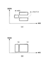
上述の実施の形態においては、図2に示したようにデータチャネル33と制御チャネル34とを近接させて配置した場合について述べたが、本発明はこれに限らず、図8に示すように、例えばIFFT部16(図1)を制御することによって、制御チャネル34とデータチャネル33との間にガード周波数帯111、112を設けるようにしてもよい。このようにすれば、バンドパスフィルタ44(図3)の通過帯域幅を広くすることができ、この分、フィルタ構成の回路規模を小さくすることができる。
(Other embodiments)
In the above embodiment, the case where the
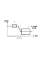
また、上述の実施の形態においては、図8に示したように、制御チャネル34とデータチャネル33との間のガード周波数帯111及び112を同じ幅とする場合について述べたが、本発明はこれに限らず、図9(A)及び(B)に示すように、ガード周波数帯121(131)と122(132)とを異なる幅とするようにしてもよい。このようにすれば、マルチセル環境において、無線送信装置としての複数の基地局が同時に制御チャネル34とデータチャネル33とを送信しているときに、無線受信装置である複数の各移動局の送信周波数帯域の中心周波数fcを、中心周波数fc1及びfc2のようにセルごとにずらして運用することにより、セル間で異なる周波数で制御チャネル34を使用しながら(制御チャネル34をFDMA(Frequency Division Multiple Access)構成として)、制御チャネル34とデータチャネル33とのローカル信号は同じ周波数を使用することができる。
In the above-described embodiment, as shown in FIG. 8, the case where the
そして、ガード周波数の大きさ(幅)を例えばIFFT部16を制御することによって変更することにより、マルチセル環境において、近隣のセルの状況に応じて適応的に制御チャネル34の配置を変更することが可能となり、制御チャネル34の干渉を低減することができる。この場合、無線送信装置10が移動局である場合において、当該無線送信装置10によって近接セルに関する情報を受信信号から測定し、当該測定結果を使用してガード周波数の幅を変更することにより、実際に測定された情報を基にガード周波数を制御することができる。
Then, by changing the size (width) of the guard frequency by controlling, for example, the
また、上述の実施の形態においては、制御チャネル34としてサブキャリア32を1本のみ用いる場合について述べたが、本発明はこれに限らず、例えば図10に示すように、複数のサブキャリア32を用いるようにしてもよい。このようにすれば、無線受信装置である各移動局は、必要な制御チャネルだけを取り出して受信することができる。
In the above-described embodiment, the case where only one
また、図11に示すように、制御チャネル34に対してナイキストフィルタ141によるナイキストフィルタ処理を施して送信することにより、他のサブキャリア(データチャネルのサブキャリア31)に対する干渉を抑えることができ、かつ、無線受信装置側においても、ナイキストフィルタを使用することにより、符号間干渉を抑えて受信することができ、受信性能を向上させることができる。
Further, as shown in FIG. 11, by performing the Nyquist filter processing by the Nyquist filter 141 on the
また、制御チャネル34として、着信があることを示すページングチャネルを適用することにより、通話を行っていない場合には、無線受信装置側でのアナログデジタル変換部のサンプリングレートを下げることができ、この分、無線受信装置の消費電力を低減することができる。
In addition, by applying a paging channel indicating that there is an incoming call as the
10,60 無線送信装置
11 拡散部
14,65 多重化部
16,67 IFFT部
18,43,69,94 乗算部
44,83 バンドパスフィルタ
45,84 アナログデジタル変換部
48,87 FFT部
52,90 逆拡散部
93 MCS解読部
DESCRIPTION OF
Claims (6)
前記所定の周波数帯と前記両側の周波数帯との間に互いに異なる幅のガード周波数帯を設ける設定手段と、 Setting means for providing guard frequency bands having different widths between the predetermined frequency band and the frequency bands on both sides;
を具備する無線送信装置。 A wireless transmission device comprising:
請求項1記載の無線送信装置。 The wireless transmission device according to claim 1.
請求項2記載の無線送信装置。 The wireless transmission device according to claim 2.
前記所定の周波数帯と前記両側の周波数帯との間に互いに異なる幅のガード周波数帯を設ける、 Providing guard frequency bands having different widths between the predetermined frequency band and the frequency bands on both sides;
ガード周波数帯設定方法。 Guard frequency band setting method.
Priority Applications (1)
| Application Number | Priority Date | Filing Date | Title |
|---|---|---|---|
| JP2005209034A JP4150388B2 (en) | 2005-07-19 | 2005-07-19 | Wireless transmission device and guard frequency band setting method |
Applications Claiming Priority (1)
| Application Number | Priority Date | Filing Date | Title |
|---|---|---|---|
| JP2005209034A JP4150388B2 (en) | 2005-07-19 | 2005-07-19 | Wireless transmission device and guard frequency band setting method |
Related Parent Applications (1)
| Application Number | Title | Priority Date | Filing Date |
|---|---|---|---|
| JP2005079876A Division JP4041505B2 (en) | 2005-03-18 | 2005-03-18 | Wireless transmission apparatus and wireless transmission method |
Publications (3)
| Publication Number | Publication Date |
|---|---|
| JP2005333671A JP2005333671A (en) | 2005-12-02 |
| JP2005333671A5 JP2005333671A5 (en) | 2007-10-04 |
| JP4150388B2 true JP4150388B2 (en) | 2008-09-17 |
Family
ID=35487941
Family Applications (1)
| Application Number | Title | Priority Date | Filing Date |
|---|---|---|---|
| JP2005209034A Expired - Lifetime JP4150388B2 (en) | 2005-07-19 | 2005-07-19 | Wireless transmission device and guard frequency band setting method |
Country Status (1)
| Country | Link |
|---|---|
| JP (1) | JP4150388B2 (en) |
Families Citing this family (25)
| Publication number | Priority date | Publication date | Assignee | Title |
|---|---|---|---|---|
| US9661519B2 (en) | 2003-02-24 | 2017-05-23 | Qualcomm Incorporated | Efficient reporting of information in a wireless communication system |
| US7218948B2 (en) | 2003-02-24 | 2007-05-15 | Qualcomm Incorporated | Method of transmitting pilot tones in a multi-sector cell, including null pilot tones, for generating channel quality indicators |
| US8811348B2 (en) | 2003-02-24 | 2014-08-19 | Qualcomm Incorporated | Methods and apparatus for generating, communicating, and/or using information relating to self-noise |
| US9544860B2 (en) | 2003-02-24 | 2017-01-10 | Qualcomm Incorporated | Pilot signals for use in multi-sector cells |
| GB2416959B (en) * | 2004-07-30 | 2009-06-17 | Kyocera Corp | Communications systems |
| RU2007117711A (en) | 2004-10-14 | 2008-11-20 | Квэлкомм Флэрион Текнолоджиз, Инк. (Us) | METHODS AND DEVICE FOR DETERMINING, TRANSMITTING, AND USING INFORMATION THAT MAY BE USED FOR INTERFERENCE MANAGEMENT |
| US8503938B2 (en) | 2004-10-14 | 2013-08-06 | Qualcomm Incorporated | Methods and apparatus for determining, communicating and using information including loading factors which can be used for interference control purposes |
| US9191840B2 (en) | 2005-10-14 | 2015-11-17 | Qualcomm Incorporated | Methods and apparatus for determining, communicating and using information which can be used for interference control |
| US8989084B2 (en) | 2005-10-14 | 2015-03-24 | Qualcomm Incorporated | Methods and apparatus for broadcasting loading information corresponding to neighboring base stations |
| US20070149132A1 (en) | 2005-12-22 | 2007-06-28 | Junyl Li | Methods and apparatus related to selecting control channel reporting formats |
| US9148795B2 (en) | 2005-12-22 | 2015-09-29 | Qualcomm Incorporated | Methods and apparatus for flexible reporting of control information |
| US9451491B2 (en) | 2005-12-22 | 2016-09-20 | Qualcomm Incorporated | Methods and apparatus relating to generating and transmitting initial and additional control information report sets in a wireless system |
| US9119220B2 (en) | 2005-12-22 | 2015-08-25 | Qualcomm Incorporated | Methods and apparatus for communicating backlog related information |
| US20070253449A1 (en) | 2005-12-22 | 2007-11-01 | Arnab Das | Methods and apparatus related to determining, communicating, and/or using delay information |
| US8437251B2 (en) | 2005-12-22 | 2013-05-07 | Qualcomm Incorporated | Methods and apparatus for communicating transmission backlog information |
| US9572179B2 (en) | 2005-12-22 | 2017-02-14 | Qualcomm Incorporated | Methods and apparatus for communicating transmission backlog information |
| US9125092B2 (en) | 2005-12-22 | 2015-09-01 | Qualcomm Incorporated | Methods and apparatus for reporting and/or using control information |
| US8514771B2 (en) | 2005-12-22 | 2013-08-20 | Qualcomm Incorporated | Methods and apparatus for communicating and/or using transmission power information |
| US9125093B2 (en) | 2005-12-22 | 2015-09-01 | Qualcomm Incorporated | Methods and apparatus related to custom control channel reporting formats |
| US9137072B2 (en) | 2005-12-22 | 2015-09-15 | Qualcomm Incorporated | Methods and apparatus for communicating control information |
| US9338767B2 (en) * | 2005-12-22 | 2016-05-10 | Qualcomm Incorporated | Methods and apparatus of implementing and/or using a dedicated control channel |
| US9473265B2 (en) | 2005-12-22 | 2016-10-18 | Qualcomm Incorporated | Methods and apparatus for communicating information utilizing a plurality of dictionaries |
| US20070243882A1 (en) | 2006-04-12 | 2007-10-18 | Qualcomm Incorporated | Method and apparatus for locating a wireless local area network associated with a wireless wide area network |
| WO2007126326A1 (en) * | 2006-04-27 | 2007-11-08 | Intel Corporation | Techniques to compress modulation patterns for adaptive bitloading |
| KR101132537B1 (en) | 2006-11-01 | 2012-04-02 | 콸콤 인코포레이티드 | Sub-band dependent resource management |
-
2005
- 2005-07-19 JP JP2005209034A patent/JP4150388B2/en not_active Expired - Lifetime
Also Published As
| Publication number | Publication date |
|---|---|
| JP2005333671A (en) | 2005-12-02 |
Similar Documents
| Publication | Publication Date | Title |
|---|---|---|
| JP4150388B2 (en) | Wireless transmission device and guard frequency band setting method | |
| JP2003309533A (en) | Wireless transmitter, wireless receiver, and method thereof | |
| JP4701300B2 (en) | Communication method and wireless transmitter | |
| EP1988731B1 (en) | Method for establishing a parameterized wireless communication channel | |
| JP4823756B2 (en) | Mobile communication system, base station apparatus, and frequency allocation method for mobile communication system | |
| US8411766B2 (en) | System and method for utilizing spectral resources in wireless communications | |
| JP2007312114A (en) | Wireless communication system and wireless communication method | |
| JP4041505B2 (en) | Wireless transmission apparatus and wireless transmission method | |
| JP4490999B2 (en) | Wireless transmission apparatus and wireless transmission method | |
| JP5079029B2 (en) | Radio transmitting apparatus, radio receiving apparatus and methods thereof | |
| JP2004254335A (en) | Radio base station and radio terminal | |
| JPH11275036A (en) | Communication terminal equipment, base station communication device, and radio communication system | |
| JP3962008B2 (en) | Wireless communication system, wireless communication apparatus, and wireless communication method | |
| JP5260131B2 (en) | Base station, mobile station, and common information communication method | |
| JP2006345243A (en) | Base station apparatus, communication terminal equipment, and transmission method | |
| JP2009194481A (en) | Reception device and reception method |
Legal Events
| Date | Code | Title | Description |
|---|---|---|---|
| A521 | Request for written amendment filed |
Free format text: JAPANESE INTERMEDIATE CODE: A523 Effective date: 20070817 |
|
| A977 | Report on retrieval |
Free format text: JAPANESE INTERMEDIATE CODE: A971007 Effective date: 20071108 |
|
| A131 | Notification of reasons for refusal |
Free format text: JAPANESE INTERMEDIATE CODE: A131 Effective date: 20080115 |
|
| A521 | Request for written amendment filed |
Free format text: JAPANESE INTERMEDIATE CODE: A523 Effective date: 20080312 |
|
| TRDD | Decision of grant or rejection written | ||
| A01 | Written decision to grant a patent or to grant a registration (utility model) |
Free format text: JAPANESE INTERMEDIATE CODE: A01 Effective date: 20080603 |
|
| A01 | Written decision to grant a patent or to grant a registration (utility model) |
Free format text: JAPANESE INTERMEDIATE CODE: A01 |
|
| A61 | First payment of annual fees (during grant procedure) |
Free format text: JAPANESE INTERMEDIATE CODE: A61 Effective date: 20080627 |
|
| FPAY | Renewal fee payment (event date is renewal date of database) |
Free format text: PAYMENT UNTIL: 20110704 Year of fee payment: 3 |
|
| R150 | Certificate of patent or registration of utility model |
Ref document number: 4150388 Country of ref document: JP Free format text: JAPANESE INTERMEDIATE CODE: R150 |
|
| FPAY | Renewal fee payment (event date is renewal date of database) |
Free format text: PAYMENT UNTIL: 20110704 Year of fee payment: 3 |
|
| FPAY | Renewal fee payment (event date is renewal date of database) |
Free format text: PAYMENT UNTIL: 20120704 Year of fee payment: 4 |
|
| FPAY | Renewal fee payment (event date is renewal date of database) |
Free format text: PAYMENT UNTIL: 20120704 Year of fee payment: 4 |
|
| FPAY | Renewal fee payment (event date is renewal date of database) |
Free format text: PAYMENT UNTIL: 20130704 Year of fee payment: 5 |
|
| S533 | Written request for registration of change of name |
Free format text: JAPANESE INTERMEDIATE CODE: R313533 |
|
| R350 | Written notification of registration of transfer |
Free format text: JAPANESE INTERMEDIATE CODE: R350 |
|
| S111 | Request for change of ownership or part of ownership |
Free format text: JAPANESE INTERMEDIATE CODE: R313113 |
|
| R350 | Written notification of registration of transfer |
Free format text: JAPANESE INTERMEDIATE CODE: R350 |
|
| R250 | Receipt of annual fees |
Free format text: JAPANESE INTERMEDIATE CODE: R250 |
|
| R250 | Receipt of annual fees |
Free format text: JAPANESE INTERMEDIATE CODE: R250 |
|
| S131 | Request for trust registration of transfer of right |
Free format text: JAPANESE INTERMEDIATE CODE: R313135 |
|
| SZ02 | Written request for trust registration |
Free format text: JAPANESE INTERMEDIATE CODE: R313Z02 |
|
| S131 | Request for trust registration of transfer of right |
Free format text: JAPANESE INTERMEDIATE CODE: R313135 |
|
| SZ02 | Written request for trust registration |
Free format text: JAPANESE INTERMEDIATE CODE: R313Z02 |
|
| R350 | Written notification of registration of transfer |
Free format text: JAPANESE INTERMEDIATE CODE: R350 |
|
| R250 | Receipt of annual fees |
Free format text: JAPANESE INTERMEDIATE CODE: R250 |
|
| R250 | Receipt of annual fees |
Free format text: JAPANESE INTERMEDIATE CODE: R250 |
|
| R250 | Receipt of annual fees |
Free format text: JAPANESE INTERMEDIATE CODE: R250 |
|
| R250 | Receipt of annual fees |
Free format text: JAPANESE INTERMEDIATE CODE: R250 |
|
| S131 | Request for trust registration of transfer of right |
Free format text: JAPANESE INTERMEDIATE CODE: R313135 |
|
| S531 | Written request for registration of change of domicile |
Free format text: JAPANESE INTERMEDIATE CODE: R313531 |
|
| R350 | Written notification of registration of transfer |
Free format text: JAPANESE INTERMEDIATE CODE: R350 |
|
| R250 | Receipt of annual fees |
Free format text: JAPANESE INTERMEDIATE CODE: R250 |
|
| EXPY | Cancellation because of completion of term |