JP4150133B2 - Multipolar rotating electrical machine and its sensing method - Google Patents
Multipolar rotating electrical machine and its sensing method Download PDFInfo
- Publication number
- JP4150133B2 JP4150133B2 JP19580899A JP19580899A JP4150133B2 JP 4150133 B2 JP4150133 B2 JP 4150133B2 JP 19580899 A JP19580899 A JP 19580899A JP 19580899 A JP19580899 A JP 19580899A JP 4150133 B2 JP4150133 B2 JP 4150133B2
- Authority
- JP
- Japan
- Prior art keywords
- sensor
- rotor
- electrical machine
- rotating electrical
- stator
- Prior art date
- Legal status (The legal status is an assumption and is not a legal conclusion. Google has not performed a legal analysis and makes no representation as to the accuracy of the status listed.)
- Expired - Fee Related
Links
- 238000000034 method Methods 0.000 title claims description 11
- 238000001514 detection method Methods 0.000 claims description 33
- 239000011295 pitch Substances 0.000 claims description 23
- 230000003287 optical effect Effects 0.000 claims description 15
- 230000005284 excitation Effects 0.000 claims description 12
- 238000004804 winding Methods 0.000 claims description 9
- 230000005405 multipole Effects 0.000 claims description 7
- 230000000149 penetrating effect Effects 0.000 claims description 2
- 238000010586 diagram Methods 0.000 description 17
- XEEYBQQBJWHFJM-UHFFFAOYSA-N Iron Chemical compound [Fe] XEEYBQQBJWHFJM-UHFFFAOYSA-N 0.000 description 16
- 229910052742 iron Inorganic materials 0.000 description 8
- 230000004907 flux Effects 0.000 description 7
- 239000000696 magnetic material Substances 0.000 description 7
- 238000007493 shaping process Methods 0.000 description 4
- 230000006698 induction Effects 0.000 description 3
- 238000005259 measurement Methods 0.000 description 3
- 230000035945 sensitivity Effects 0.000 description 3
- 229910000831 Steel Inorganic materials 0.000 description 2
- 230000000694 effects Effects 0.000 description 2
- 230000005389 magnetism Effects 0.000 description 2
- 239000010959 steel Substances 0.000 description 2
- 230000015572 biosynthetic process Effects 0.000 description 1
- 238000004364 calculation method Methods 0.000 description 1
- 238000006243 chemical reaction Methods 0.000 description 1
- 238000006073 displacement reaction Methods 0.000 description 1
- 238000005516 engineering process Methods 0.000 description 1
- 238000010030 laminating Methods 0.000 description 1
- 238000004519 manufacturing process Methods 0.000 description 1
- 239000000463 material Substances 0.000 description 1
- 230000010363 phase shift Effects 0.000 description 1
- 238000004080 punching Methods 0.000 description 1
- 239000011347 resin Substances 0.000 description 1
- 229920005989 resin Polymers 0.000 description 1
- 229920006395 saturated elastomer Polymers 0.000 description 1
- 239000004065 semiconductor Substances 0.000 description 1
- 230000001360 synchronised effect Effects 0.000 description 1
Images


Landscapes
- Brushless Motors (AREA)
- Control Of Direct Current Motors (AREA)
Description
【0001】
【発明の属する技術分野】
本発明は、回転電機のクローズドループ制御に有効な多極回転電機とそのセンシング方法、特に、複写機等に使用されるステッピングモータ等の多極回転電機のクローズドループ制御に最適な、精度が良く始動時にも安定に作動する安価で高性能の多極回転電機とそのセンシング方法に関する。
【0002】
【従来の技術】
小型回転電機で、回転子の現在位置や、現在速度等の情報をフィードバックしてクローズドループ制御を行うようにしたブラシレスモータが、オープンループ駆動のステッピングモータに比べて、無負荷運転時の消費電力の低減、効率向上、回転ムラの低減等に大きな効果が得られるので、近時、複写機等のOA機器等で活用されるようになっている。
一般的なブラシレスモータの回転子極数は、回転子外形が30mm程度のモータでは14極程度以下である。
このような構造のブラシレスモータの回転制御用のセンサーとしては、一般に、図14又は図15に示すように、ホール素子や磁気抵抗素子等の磁気感応素子をエアギャップを介して回転子磁極に対向させる手段が使用されている。
【0003】
図14及び図15はセンシング機能の説明をするために、回転電機としての詳細構成は省略して示している。
図14において、101は回転電機の固定子、102は固定子に巻装したコイル、103は周囲に磁極を着磁して形成した回転軸105を中心にして回転する回転子、108は回転子の磁極を検知するホール素子である。
即ち、ホール素子108によって、回転子103に形成した回転磁極を検出し、この検出信号によってコイル102に励磁電流を流すタイミングを設定することによって、回転電機の固定子101は、所望の回転速度で回転する。
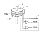
例えば、回転子の極数が32極から100極という多極の場合は、円周に沿って多数のスリットを設けた円板に光を透過させ、ホトダイオード等の光感応素子で検知するようにしたパルスエンコーダ等をモータ外部の回転軸に装着する光学式センシング手段か、図15に示すように磁気抵抗素子を利用した磁気エンコーダを回転軸に装着する手段が採用されている。
図15において、113は円筒の周囲に回転方向に着磁した磁気ドラム部分113aを形成した回転子である。なお、115はその回転軸である。回転子113の回転によって発生する磁気の変化は磁気抵抗素子118によって検出され、コンパレータ119によって励磁電流の指令信号を作成するようにしている。
多極回転子の場合には、回転子の誘導速度起電力を利用する手段も利用されている。
【0004】
【発明が解決しようとする課題】
上述したような、多極回転電機を、ホール素子のような磁気感応素子をエアギャップを介して回転子磁極に直接対向させるセンシング方法で、電気角30度に位置決めする場合は、回転子の磁極数が100極の場合の機械角は、電気角で極対数を割った値、即ち、0.6度になる。従って、僅かな機械角のづれが大きな角度誤差となるので、量産時に、回転子磁極とホール素子間の必要な位置精度が得られないと、均一な特性が得られなくなる。
また、ホール素子は磁気感応部は外皮が厚めの樹脂で覆われているため、磁気感応部と対向部との間隔が大きくなるので、位置決め精度を低下させる原因にもなっている。
そのために、前述のように、多極回転電機には採用されないでいた。
【0005】
光学式や磁気式のエンコーダを取り付けて回転子の位置情報を得る手段では、回転子が多極の場合は、エンコーダの分解能もそれなりに増加する必要があるために、僅かな機械角度の狂いでも大きな電気角度誤差になるため、エンコーダとの位置合わせのための調整時間がかかり、コスト高になる原因になっていた。
永久磁石式回転電機は、回転子に形成される磁極との対応で、速度起電力が最大になる相のコイルを励磁すると、界磁と電流が直交するので、最大トルクで駆動できる。しかし、回転子の巻線に誘導される回転子の誘導速度起電力をセンサーとして使用する方式では、始動時には速度が零のため、誘導速度起電力が無いので始動時にはセンサーとして利用できず、始動時には、ステッピングモータのように、オープンループで始動する必要があった。
【0006】
上述のように、従来のクローズドループ制御に使用される回転電機は、回転子外形が30mm程度のモータでは14極程度以下であり、回転子の極数が32極から100極のように多極の場合は、外部に、専用のセンサーを装着する必要があるので、調整費用を含めて、高価にならざるを得ないという問題点があった。
また、ステッピングモータはオープンループによる制御方法なので、回転精度がクローズドループよりも明らかに落ちるという問題があった。
【0007】
本発明は、従来のものの上記課題(問題点)を解決し、ステッピングモータ等の多極回転電機のクローズドループ制御を可能にするに最適な、精度が良く、始動時にも安定に作動する安価で高性能のクローズドループ制御を可能にする、センサーを一体に形成した多極回転電機とそのセンサーのセンシング方法を提供することを目的とする。
【0008】
【課題を解決するための手段】
本発明に基づく多極回転電機は、略環状の磁性体内面から円中心に向け求心状に等ピッチに配設し夫々が励磁用の巻線を巻装して先端部に複数所定個の磁歯を設けた主極を形成した3相の固定子と、この固定子の磁歯表面との間に所定のエアギャップを設けて、回転方向にNr個の磁歯を有するギヤ状の磁性体2個の間に軸方向に磁化した永久磁石を挟持したハイブリッド型回転子、又は、回転方向に各Nr個のN極、S極同数の永久磁石を交互に円筒状に形成した円筒状永久磁石形回転子を、回転自在に支承して設けた回転電機において、略前記の固定子に連結する環状の磁性体内面から円中心に向け求心状に等ピッチに、この回転電機を形成する相数又は相数の整数倍のセンサー用固定子極を配設し、このセンサー用固定子極の所定位置にセンサーを装着して先端部に誘導子を形成し、前記固定子に所定のエアギャップを介して構成したセンサー用固定子と、このセンサー用固定子極の誘導子との間に所定のエアギャップを設けて、回転軸に固定して回転方向に前記センサーに対応する被回転検出体を形成したことを特徴とする。
【0009】
上記の回転電機において、この回転電機自体の固定子に連結する環状の磁性体内面から円中心に向け求心状に等ピッチにこの回転電機を形成する相数又は相数の整数倍のセンサー用固定子極を配設し、このセンサー用固定子極夫々の所定位置にセンサーとして磁気感応素子を装着して先端部に誘導子を形成し、所定のエアギャップを介して構成したセンサー用固定子と、このセンサー用固定子の誘導子に対応し所定ギャップを介して、この回転電機自体の回転子と同軸上にNr又はNrの整数倍の磁歯を有するギヤ状の磁性体2個の間に軸方向に磁化した永久磁石を挟持したセンサー用ハイブリッド型回転子、又はこの回転電機自体の回転子と同軸上に極対数がNr個又はNrの整数倍個のN極、S極同数の永久磁石を交互に円筒状に形成したセンサー用永久磁石形回転子によって被回転検出体を形成し、磁気感応素子がセンサー用回転子に形成した磁極を検知することにより回転子の位置を検知するように形成するのが望ましい。
但し、Nr=m(3n±1)・・・・・・・(1A)又は、
Nr=m(6n±1)/2・・・・(1B)
また、m≧2の整数、n≧1の整数である。
又は、これに代え、上記の回転電機において、この回転電機自体の固定子に連結する環状の磁性体内面から円中心に向け求心状に等ピッチにこの回転電機を形成する相数又は相数の整数倍のセンサー用固定子極を配設し、このセンサー用固定子極夫々の所定位置にセンサーとしてコイルを巻装して先端部に誘導子を形成し、所定のエアギャップを介して構成したセンサー用固定子と、このセンサー用固定子の誘導子に対応し所定ギャップを介して、この回転電機自体の回転子と同軸上にNr又はNrの整数倍の磁歯を有するギヤ状の磁性体で形成したセンサー用回転子によって被回転検出体を形成し、上記のコイルのインダクタンスがセンサー用回転子に形成した磁歯の有無によって変化することにより回転子の位置を検知するようにしても良い。上記において、Nrは(1A)式又は(1B)式を満足するように形成する。なお、当該回転電機を構成する相数が3であるのに対し、センサー用固定子極数を2または2の倍数とし、上記センサー用コイルの出力信号が相互に電気角で90度の位相差を有するように形成しても良い。
【0010】
上記の回転電機において、形成するセンサー用固定子極は、この多極回転電機自体の固定子に形成する磁極と磁極位置を対応させると共に、被回転検出体に形成した磁極対数又は磁歯数に対応させて、複数所定個の誘導子を形成する磁歯を各所定個、等ピッチで設けるのが望ましい。
また、上記のセンサー用固定子極先端の誘導子と、回転軸に固定した被回転検出体とは所定のエアギャップを介して同一円周上で相互に対向させて形成されるようにしても良く、上記のセンサー用固定子極先端の誘導子と、回転軸に固定した被回転検出体とは夫々の側面を所定のエアギャップを介して相互に対面させて形成するようにしても良い。
本願発明においては、さらに、適用対象の回転電機において、この回転電機自体の回転子に形成した円筒状永久磁石と回転軸との間に形成した中子にNr個又はNrに比例する個数の所定形状のスリットを設けて、中子自体を被回転検出体とし、この回転電機を形成する相数又は相数の整数倍のセンサー用固定子極をこの被回転検出体に対して所定のエアギャップを介して対面するように配設し、センサー用固定子極夫々の端面所定位置に上記のスリットに対応した形状の複数所定個の、誘導子を形成する磁歯を形成し、この磁歯群にコイルを巻装して誘導子を形成し、このコイルのインダクタンスが被回転検出体に形成したスリットの有無によって変化することにより回転子の位置を検知するようにすることができる。
上記において、Nrは(1A)式又は(1B)式を満足するように形成する。
【0011】
上記のセンサー用固定子極は、この多極回転電機自体の固定子に形成する磁極と磁極位置に対応させると共に、被回転検出体に形成した磁極対数又は磁歯数に対応させて、複数所定個の誘導子を形成する磁歯を各所定個設けるようにしてセンサーとして磁気感応素子を形成した場合に、この多極回転電機自体の回転子に形成される磁極と、センサー用回転子に形成される磁極又は磁歯の回転子方向位置偏位をθr、任意の相の固定子主極に形成する磁歯とセンサー用固定子の対応する誘導子を形成する磁歯との回転子回転方向の位置偏位をθsとし、下式を満足するように形成するのが望ましい。
但し、0≦θr≦360/Nr・・・・・・・・(2A)
0≦θs≦120/Nr・・・・・・・(2B)
また、Nrは回転子極対数
θr=0のときは、θs≠0・・・・・・・・・・(3A)
θs=0のときは、θr≠0・・・・・・・・・・(3B)
さらに、上記の回転電機において、当該回転電機の回転子の外径をD1、当該回転電機の反出力軸側軸受の外径をD2、センサー用回転子の外径をD3とし、該D1、D2、D3を下式を満足するように形成して、センサー用固定子とセンサー用回転子の対を当該回転電機の反出力軸側軸受の外部に形成しても良い。
D1>D2>D3・・・・・・・・・・(4A)
上記において、回転電機の反出力軸側軸受装着機構にスラスト受けを形成してる場合は、反出力軸側軸受装着孔の内径をD2′とし、下式を満足するように形成する。
D1>D2′>D3・・・・・・・・・・(4B)
また、略環状の磁性体内面から円中心に向け求心状に等ピッチに配設し夫々が励磁用の巻線を巻装して先端部に複数所定個の磁歯を等ピッチで設けた主極を形成した3相の固定子と、この固定子の磁歯表面との間に所定のエアギャップを設けて、回転方向にNr個の磁歯を有するギヤ状の磁性体2個の間に軸方向に磁化した永久磁石を挟持したハイブリッド型回転子、又は、回転方向に各Nr個のN極、S極同数の永久磁石を交互に円筒状に形成した円筒状永久磁石形回転子を、回転自在に支承して設けた回転電機において、上記の回転子を軸方向に同心的に貫通するNr個又はNrに比例する個数のスリット部を形成するか、回転方向にNr個又はNrに比例する個数の小歯を有するギヤ状の回転体を形成して被回転検出体を形成し、上記スリット又は小歯の間隙を貫通し、上記固定子に形成する主極に対応する位置に光センサーを設け、この光センサーによってスリット位置を検出するようにしても良い。
【0012】
上記において、Nrは(1A)式又は(1B)式を満足するように形成する。
上記のコイルをセンサーとして形成した回転電機において、このセンサー用コイルをチョッピング回路に形成し、コイルインダクタンスによるチョッピング周期又はデュテイの変化を検知して回転子の位置情報を得るようにしても良い。
また、センサー用コイルに交番電圧を供給し、コイルインダクタンスによる電流値の変化を検知することによって回転子の位置情報を得るようにしても良い。
また、上記の磁気感応素子をセンサーとして形成した回転電機において、該磁気感応素子にホール素子を使用するのが望ましい。
【0013】
上述のような構成によると、安価なホール素子のような磁気感応素子やコイル、又は、光センサーを、回転電機自体の固定子や回転子の部品、又は、加工手段を流用できる類似構造のもので簡単に構成しながら、多極回転電機のクローズドループ制御用の精度の良いセンサーとして使用できる。
センサーに磁気感応機能を使用し、センサー用固定子極に誘導子としての磁歯を設けた場合は、この磁歯部に回転子磁束を導き、それを集めて磁気感応素子に導いて磁気変化を検知できるので、センサーの装着位置精度として特別の考慮をしないでも所望される計測精度が得られる。
センサー用回転子の周囲をギヤ状に形成した場合は、材料が安価な磁性鉄板で良く、温度等に影響され難い安定度の高い位置決めができる。
円筒磁石型回転子の中子にスリットを設けた場合は、特別のセンサー用回転子の構成をせず、誘導速度電圧を利用しないでも良いので、始動時から、精度良く回転子位置を検出できる。
センサーとしてコイルのインダクタンス変化を利用した場合は、簡単な構造と構成で所望される精度で回転子位置を検出できる。
センサーとして光の通過変化を利用した場合も、簡単な構造と構成で所望される精度で回転子位置を検出できる。
【0014】
【発明の実施の形態】
以下に、本発明の各実施の形態を図面を参照して詳細に説明する。
実施の形態1:実施の形態1は、3相式6極の永久磁石形回転電機に、本発明の請求項2に記載する手段を適用した例を示している。図3は、本発明を適用する3相式6極の永久磁石形回転電機の横断面を示す図であって、1は固定子で相数の所定倍、即ち、本実施の形態では3相6極として6個の固定子主極1Aを形成させている。図3において、6個の主極は略環状の磁性体内面から円中心に向け求心状に等ピッチに配設され、各主極1A夫々には励磁用のコイル2を巻装して先端部に複数所定個の極歯となる磁歯1aを等ピッチで設けている。また、磁歯1aの内面との間に所定のエアギャップを介して、図示しない軸受によって回転自在に支承される回転軸5に固着される回転子3が、磁性鉄等の磁性材で形成する中子4を介して、周囲に永久磁石3Aを回転方向に永久磁石のN極、S極を交互にNr対形成し、円筒式永久磁石型回転子を形成している。
但し、Nr=m(3n±1)・・・・・・・(1A)
Nr=m(6n±1)/2・・・・(1B)
を満足するように形成されている。また、m≧2の整数、n≧1の整数である。図3は、上記(1A)式を満足し、m=2、n=3の場合を構成している。即ち、3相であるから、主極数は6で、(1A)式から、Nr=2(3×3−1)=16になり、ステップ角θは、θ=60/Nrの関係にあるから、θ=3.75度の回転電機である。(1B)式が適用される回転電機は、例えば、HB型3相ステッピングモータで、m=4で12極、n=4の場合は、(1B)式から、Nr=4(6×4+1)/2=50で、ステップ角θは、θ=60/Nrの関係にあるから、θ=1.2度の回転電機になる。以下の説明においては、ステッピングモータに位置検出用のセンサーを内蔵させてクローズドループ制御を実行することも含め、本発明を適用する多極回転電機を回転電機と称して説明する。
【0015】
図1、図2によって、この回転電機に構成されるセンシングシステムを説明する。
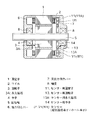
図1は、図3に示す回転電機の縦断正面図であるが、図示の都合上、図2に示すように相互に120度隔てて配置される磁気感応素子U1、V1、W1を同一形状で示すために回転電機を120度の間隔で縦断して示している。
図1において、夫々、1は固定子、2はコイル、5は回転軸であり、6は出力側カバー、7は反出力側カバー、8は軸受である。
また、11は固定子1に固定される詳細を後述するセンサー用固定子極11Aを備えたセンター用固定子で、ホール素子等の磁気感応素子U1(及びV1、W1)をセンサーとして備えている。13は、詳細を後述する被検出体としての機能を備えたセンサー用回転子である。(以下の説明では被検出体という用語をできるだけ使用せず、センサー用回転子というような機能名で説明する。)
【0016】
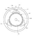
図2は、図1を右側からみたセンサーシステムを示していて、固定子1と同一又は相当の所定特性の鉄材等の磁性材料で形成されたセンサー用固定子極11Aは、略環状の磁性体内面から円中心に向け求心状に等ピッチに配設され、先端部に所定数の磁歯11aを誘導子として備え、環状の磁性体と磁歯11a部との間にヨーク部11bを形成している。
各固定子極11Aのヨーク部11bには、磁気感応素子より成るセンサーU1、V1、W1、例えば、ホール素子が装着されている。
また、磁歯11aの内面との間に所定のエアギャップを介して、図示しない軸受によって回転自在に支承される回転軸5に固着されるセンサー用回転子13が構成されている。センサー用回転子は、永久磁石13Aを回転方向にN極とS極を交互に、Nr対又はNrの倍数対形成した円筒状永久磁石が、磁性鉄等の磁性材で形成する中子14によって回転軸5に固定されている。
本実施の形態では、3相各1個のセンサー用固定子極を形成した例を示している。しかしながら、3相機の励磁タイミングを設定するためのセンサー用固定子極としては、3の倍数である、3、6、9、12、等であれば良いことは当然である。
【0017】
上記において、センサーU1の検知信号は3相回転電機におけるU相の位置検出用に、センサーV1の検知信号は3相回転電機におけるV相の位置検出用に、センサーW1の検知信号は3相回転電機におけるW相の位置検出用に夫々使用される。
各ヨーク部11bの先端に、誘導子として機能する固定子主極1Aと相当形状で上記センサー用回転子の周囲に形成した永久磁石の対数と対応させた数の磁歯11aが前述したように、誘導子として形成されている。
誘導子は、センサー用回転子に形成した永久磁石の磁束を効率良くまた精度良くセンサーU1、V1、W1に導く機能を有している。
各センサー用固定子極に対するセンサーの装着位置は、該ヨーク部11bの形状と誘導子の磁歯11aの形状等に対応して、適切な感度が得られるように、該ヨークの略環状の磁性体内面から誘導子の磁歯11aとの分岐部との間の適切な位置に装着すれば良い。
【0018】
センサー用回転子13は周囲を円形にして、前述したように、回転子3の周囲に形成されるNr対のN極、S極と同数のNr対数のN極、S極を形成している。上記において、N極とS極の対数Nrは、上記の(1A)式を満足するように構成される。上記の中子4及び14は、磁性鉄等の磁性材で形成するのが望ましい。上図において、回転電機機能の永久磁石によって回転子に形成される磁極N極又はS極と、センサー用回転子13に形成される磁極N極又はS極との回転子の回転方向の位置偏位をθr、任意の相の固定子主極1Aに形成する磁歯1aとセンサー用固定子11の対応する磁歯11aとの回転子回転方向の位置偏位をθsとしたとき下記式を満足する。
0≦θr≦360/Nr・・・・・・・(2A)
0≦θs≦120/Nr・・・・・・(2B)
但し、Nrは回転子極対数
θr=0のときは、θs≠0
θs=0のときは、θr≠0
【0019】
上記のセンサー用固定子は、回転電機本体の、一般的加工手段のように、固定子が薄板磁性鋼板をプレスで打ち抜いて加工されている場合は、この加工のプレス型を利用して打ち抜き加工をすれば良い。
この場合は、各センサー用固定子の誘導子と固定子主極に形成した磁極との相互の位置関係精度が得られるので、ヨーク部にセンサーを装着する位置精度には大きく影響されないで、所望する計測精度が得られる。
【0020】
実施の形態2:
2相式4極の永久磁石形回転電機の固定子を1枚の鉄板から、プレスによる打ち抜き加工で作成できる構造にしたセンシングシステムに関し、実施の形態2として、図1及び図2によって説明する。回転子は実施の形態1と類似の構造をしているので、図1及び図2と同様の符号を使用して説明は省略する。
次に、上記の構成におけるセンサーU1、V1、W1の働きを説明する。
今、図2に示すように、U相用のセンサーU1の磁歯がセンサー用回転子13のN極に対向していると、矢印jに示すように、磁束はセンサー用固定子極11Aに形成されるが、ヨーク部11bを通る磁束kは、センサーU1の装着のために細く形成されているために、飽和して、漏洩磁束がセンサーU1を通る。従って、センサーU1は磁気を検知した信号を出力する。
上記のように、回転電機機能の永久磁石によって回転子に形成される磁極N極又はS極と、センサー用回転子13に形成される磁極N極又はS極との回転子方向位置偏位をθrに形成している。従って、クローズドループ制御機能を構成している、この回転電機の適用システムにおいて、センサーU1は、この回転電機の回転子の回転位置を精度良く検知するので、U相の励磁タイミングを決定することができる。
また、本実施の形態では3個装着しているいずれかのセンサーの出力信号の単位時間当たりの数を計数することによって、この回転電機の回転速度を計測することもできる。
【0021】
実施の形態3:
図4、図5によって、本発明に基づく、上記の実施の形態2とは別のセンサーシステムを3相ハイブリッド(以下HBと称す)型ステッピングモータに適用した実施の形態3を説明する。
図4は、前述した図1同様、回転電機の縦断正面図であって、1は固定子、2はコイル、5は回転軸であり、6は出力側カバー、7は反出力側カバー、8は軸受である。
図5は、図4を右側からみたセンサーシステムを示している。
本実施の形態の説明においては、詳細の図示説明は省略しているが、主極の数が、6個、9個、12個等で、各主極に磁歯を設けている固定子を有する回転電機(ステッピングモータ)に適用できる。
図4において、9a、9bは夫々外周にNr個の磁歯を形成させ、相互に1/2ピッチ偏位させた磁性体であって、回転軸方向に磁化した永久磁石10を挟持し、回転軸5に固着されている。
即ち、磁性体9a、9b及び永久磁石10によりHB型回転子Rを形成している。
【0022】
次に、図4、図5によってセンサーシステムの説明をする。
同図において、15は、固定子1と同一又は相当の所定特性の鉄材等の略環状の磁性材料で形成されたセンサー用固定子で、センサー用固定子極15Aは、この略環状の磁性体内面から円中心に向け求心状に等ピッチに配設され、先端部に所定数の磁歯15aを誘導子として備え、環状の磁性体と磁歯15a部との間にヨーク部15bを形成している。
各固定子極15Aのヨーク部15bには、センサーとしてコイル12が巻装されている。
また、磁歯15aの内面との間に所定のエアギャップを介して、軸受8によって回転自在に支承される回転軸5に固着されるセンサー用回転子16が構成されている。センサー用回転子16は、センサー用固定子15の誘導子(磁歯15a)に対応し所定ギャップを介して、回転電機の回転子Rと同軸上にNr又はNrの整数倍の磁歯16aを形成したギヤ状の磁性体で形成して被回転検出体を形成している。
【0023】
本実施の形態では、U相、U相、V相、V相、W相、W相の3相各2個のセンサー用固定子極を形成した例を示している。しかしながら、3相機の励磁タイミングを設定するためのセンサー用固定子極としては、3の倍数である、3、6、9、12等であれば良いことは当然である。
上記のセンサー用固定子極15Aの磁歯15aの数とピッチはセンサー用回転子16に形成する磁歯16aの数、即ち、ピッチに対応した値に形成している。従って、センサー用固定子極15Aの磁歯15aは、センサーとしての必要精度と感度との対応でその数を設定すれば良い。従って、検出感度等が許容できれば1個の磁歯でも良い。
【0024】
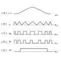
次に、図6によって上記構造の動作原理を説明する。
図6は、各相のセンサー用固定子極15A、即ち、コイル12と、センサー用回転子16に形成した磁歯16aとの位置関係に伴うインダクタンス変化を示した図であって、同図(A)は、U相のセンサー用固定子極15Aとコイル12及びセンサー用回転子の磁歯16aとの位置関係を示し、同図(B)には、同図(A)に示す位置関係に対応するU相用コイルのインダクタンス変化曲線、同図(C)には、同一タイミングにおけるV相用コイルのインダクタンス変化曲線、同図(D)には、同一タイミングにおけるW相用コイルのインダクタンス変化曲線を示している。なお、図6(A)〜(D)では、説明の便宜上、センサー用固定子極15Aの磁歯は1個に収斂し、センサー用回転子も、センサー用固定子極の磁歯に対応する全ての磁歯を1個に収斂した状態で示している。
従って、センサー用回転子の磁歯と、センサー用固定子極を夫々誘導子と称して説明する。
【0025】
図6(A)のA1は、センサー用固定子極15Aと、センサー用回転子16の誘導子が完全に対向した位置にある状態を示している。即ち、同図(B)に示すようにU−U相のコイルのインダクタンスは最大である。
センサー用回転子16が電気角で90度回転し、センサー用固定子極15Aとセンサー用回転子16夫々の誘導子の位置関係が同図A2に示すようになると、同図(B)に示すように中間値になり、さらに、センサー用回転子16が電気角で90度回転すると、図6(A)のA3に示すように、センサー用固定子極15Aとセンサー用回転子16夫々の誘導子の位置関係は、完全に非対向位置になって同図(B)に示すようにインダクタンスは最小値になる。さらに、センサー用回転子16が電気角で90度回転すると、センサー用固定子極15Aとセンサー用回転子16夫々の誘導子は、図6(A)のA4に示す位置関係になって、同図(B)に示すようにインダクタンスは中間値になる。
【0026】
この間、V相のコイルのインダクタンス値は、同図(C)に示すように、U相のコイルから電気角で120度偏位していて、V相のコイルを装着したセンサー用固定子極15Aと、センサー用回転子16の誘導子が完全に対向位置になると、V相のインダクタンス値は最大になるように変化する。
同様に、W相のコイルのインダクタンス値は、同図(D)に示すように、V相のコイルのインダクタンス特性から電気角で120度偏位して変化する。
上記のように、センサー用固定子極15Aの誘導子、即ち磁歯15aとセンサー用回転子16の誘導子、即ち磁歯16aが対向している場合と、相互の磁歯間に対向している場合で、コイル12のインダクタンス値が最大に変化するので、このようなインダクタンス変化を計測するように構成すれば、回転電機の各相に励磁すべきタイミングが判定できる。
【0027】
実施の形態4:
上記の回転電機を構成する相数Pが3である場合、センサー用固定子極数を2または2の倍数とし、センサー用コイルの出力信号が相互に電気角で90度の位相差を有するように形成する。
即ち、例えば、回転電機の相数が3の場合、センサー用固定子極数も3とすれば、3個のセンサー用コイルからは図6に示すように、相互に電気角で120度偏位する信号が得られるので、対応する回転電機各相の回転位置を検知できる。
これに対して、上記のように形成すると、各センサー用コイルの出力信号波形は図6に示すように正弦波形になり、相互に90度の位相差を有するので、この出力信号をsinθ値およびcosα値とし、三角関数の特性を利用した演算によって120度位相差を有する3相信号を作成する。
従って、この3相信号によって、センサー用固定子極と回転電機本体の固定子極位置が固定されているので、固定子極位置を検知する。
【0028】
実施の形態5:
上記の各実施の形態においては、センサー用固定子の誘導子と、センサー用回転子の誘導子又は永久磁石が回転軸上で対向するように構成されていたが、別の構成例である実施の形態5を図7によって説明する。
図7は、センサー構成部における回転電機の縦断正面図であって、17は、実施の形態1に記したセンサーを装着したセンサー用固定子、又は、実施の形態2に記したコイルを装着したセンサー用固定子に相当する形状のセンサー用固定子である。図7には、コイルを形成した図を示しているが、コイルに変えて、図2と同様、ヨーク部を狭くしてホール素子等の磁気感応素子を装着しても、後述するように、被回転検出体の構造を対応させることによって、同様に使用できる。
18は、センサー用回転子でセンサー用固定子17が、磁気感応素子を装着したセンサー用固定子に相当する場合は、実施の形態1に示したように、永久磁石のN極とS極を交互に形成したセンサー用回転子とし、センサー用固定子17が、コイルを装着したセンサー用固定子に相当する場合は、実施の形態3に示したように、先端に誘導子としての磁歯を形成したセンサー用回転子となる。
その他の符合は説明を省略するが図1と同一である。
即ち、本実施の形態では、センサー用固定子に装着したセンサーが、センサー用固定子に形成した磁歯の側面で、所定のエアギャップを介して対応するセンサー用回転子の先端部に形成した磁極又は誘導子の変化を検知するように構成したものである。
従って、センサー用固定子に装着したセンサーが効率良く対象体を検知できるように、それぞれの磁極、誘導子等を適切な形状に形成することは当然である。
【0029】
実施の形態6:
上記の1乃至3の各実施の形態においては、センサー用固定子の誘導子と、センサー用回転子の誘導子又は永久磁石が同一円周上で対向するように構成された例を示し、実施の形態5では、センサー用固定子とセンサー用回転子とが相互に側面で対向する例を示したが、別の実施の形態6を図8によって説明する。
図8において、同図(A)は、センサー構成部における回転電機の縦断正面図であって、同図(B)はセンサーシステム部の正面図を示している。また、同図(C)はその要部展開図、同図(D)はセンサー部の側面図である。
同図において、27は、実施の形態1に記したセンサーを装着したセンサー用固定子であって、側面に円周状に、この回転電機の主極数又は比例数の所定形状の突起23が磁極として形成され、所定数の磁極を一組にしてセンサーとしてコイル22を巻装している。
28は、回転軸に固着した磁性材料で構成した被測定体としてのセンサー用回転子であって、Nr個又はNrに比例する個数設けた所定形状のスリット24を、上記センサー用固定子27に形成した突起23及びコイル22に対応して設けている。
即ち、同図においては、センサー用回転子28のサイドに形成したスリット部の軸方向に所定のエアギャップを介して該スリット部に対向してコイル22を装着したセンサー用固定子を形成したものである。
即ち、上述した実施の形態3と同様、コイルのインダクタンス値の変化を感知して回転子の回転位置情報を得ることができる。
【0030】
実施の形態7:
上記の実施の形態6においては、被測定体としてセンサー用回転子を形成した例を説明したが、これとは別の実施の形態7を説明する。
詳細の図示は省略するが、前述した図1、図3に示した回転子中子4を磁性体で構成し、少なくともその片面端部近傍に、同心的にNr個又はその整数倍のスリット設け、上記図7に示したセンサー用固定子のように、このスリット部の軸方向に所定のエアギャップを介して該スリット部に対向してコイルを装着したセンサー用固定子を形成したものである。
即ち、回転電機自体の回転子を被回転検出体とし、上述した実施の形態3同様、コイルのインダクタンス値の変化を感知して回転子の回転位置情報を得ることができる。
【0031】
実施の形態8:
図9によって、センサー付き回転電機を小形にし、しかも、回転電機部とセンサー用回転体とセンサー用固定子の位置決めを容易にした実施の形態8を説明する。上記実施の形態7までに説明した要素機能の説明は省略する。
図9において、51は固定子、52はコイル、55は回転軸であり、56は出力側カバー、57は反出力側カバー、58は軸受、59は回転子である。
また、61Aは固定子51との間が固定され、センサーとしてのコイル62が巻装されたセンサー用固定子極であって、63は、詳細を後述する、被回転検出体を形成するセンサー用回転子である。
【0032】
図示は省略するが、前述した各実施の形態同様、センサー用回転子63の外周には、Nr又は同数の整数倍の磁歯が誘導子として形成され、各センサー用固定子極61Aには、この磁歯の寸法、即ちピッチに対応した数の誘導子が形成されている。
同図に示すように、回転電機自体の回転子59の外径をD1、軸受58の外径をD2、センサー用回転子の外径をD3としたとき、
D1>D2>D3・・・・・・・・・・(4A)
とし、回転子59の外部に形成した磁歯とセンサー用回転子63の外部に形成した誘導子としての磁歯は、回転中心を中心として所定角度θr偏位させて固定し、一体にして組み立てている。
上記構造において、軸受58にスラスト軸受機能を有している場合は、
反出力側カバー57に形成した軸受58装着用穴の内径をD2′とすると、
D1>D2′>D3 ・・・・・・・・・・(4B)
とする。
【0033】
上図のように組み立てるには、固定子51とセンサー用固定子61を反出力側カバー57を間にして適切に構成した治具によって位置決めして固定する。また、回転電機自体の回転子59とセンサー用回転子63を軸受58を中間にして、治具によって位置合わせをして回転軸55に固定する。
その後、前記のように構成した回転軸55を図に示す左側から、反出力側カバー57に挿入して軸受58を固定し、さらに、出力側カバー56に固定した軸受58を回転軸55を貫通するようにして、出力側カバー56を固定子51と反出力側カバー57に図示しないねじで固定する。
【0034】
実施の形態9:
図10、図11によって、回転電機自体の回転子の中子にスリットを形成した実施の形態9を説明する。
モータとしての主要要素は図1、図2と同一の符号を付して説明は省略する。
図10、図11において、回転子93の外部には、図10に示すように、図1と同様、回転軸に平行に回転方向に永久磁石N極、S極が交互の32極磁化されている。
中子94は、他の回転電機と同様、磁性薄板鉄板を打ち抜いて積層され回転軸5に固定されている。
該中子94は、図に示すように、外部に、同心に16個のスリット、a−1、a−2、・・・、a−n、・・・、a−16、その内部に3個のスリット、b−1、b−2、b−3が等間隔に設けられている。また、スリットa−1と、b−1とは、中子の中心を結ぶ半径上に形成されていて、さらに内部にスリットCが設けられている。
なお、スリットの数は、上記のような数ではなく、回転電機としての相数と主極の数に対応し、各コイルに励磁電流を供給するタイミングを決定するための回転子位置を所望される精度で計測できれば良い。
出力側カバー6、反出力側カバー7には、図10及び図11に示すように、上記スリットa−1〜a−16、b−1〜b−3及びCを貫通する光りを検知できる、光センサーとして、半導体レーザ等の発光素子97と受光素子98が、必要な精度を得られるように、回転電機の固定子極位置に対応させて所定個数、対向させて装着している。即ち、本実施の形態も、回転電機自体の回転子を被回転検出体を形成している。
【0035】
上記の構造において、回転電機が駆動され回転子93が回転すると、発光素子97と受光素子98が形成する光線を回転子93に形成したスリットが断続する。
従って、光センサーの前を上記スリットa−1〜a−16が通過すると、その通過ピッチから回転電機の回転速度が計測でき、光センサーの前を上記スリットb−1〜b−3が通過すると、その通過タイミングから、各固定子極を励磁すべきタイミングが判定でき、光センサーの前を上記スリットCが通過すると、その通過タイミングから、対応する所定の固定子極、例えば、U相の固定子極を励磁すべきタイミングが判定できる。
上記において、V相の固定子極を励磁すべきタイミングは、スリットCが通過した後にくるスリットb−1〜b−3のいずれかの通過から判定でき、W相の固定子極を励磁すべきタイミングは、スリットCが通過した2個目にくるスリットb−1〜b−3のいずれかの通過から判定できる。
【0036】
図10に示すスリットの配置は一例であって、各固定子極の位置を直接検知できるように、同一径上に形成した複数スリットの組み合わせから直接検知できる等、光センサーの配置と対応させて適切に形成すれば良い。
また、必要な各固定子極位置の検出精度と対応させて、同一固定子極位置に対応させた光センサーを同一円周上に適切に配設し、検知される複数信号を例えば、論理加算する等、そのセンシングシステム構成の論理に対応させた処理を行って得るようにしても良い。
また、上記の説明では光源と受光素子を一対一で対応させたが、どちらかを又は両方を共通にし、光学的処理で弁別できるようにしても良いことは当然である。
【0037】
実施の形態10:
詳細の図示は省略するが、実施の形態9とは別の光センサーを使用した実施の形態10を説明する。
即ち、実施の形態9では回転電機の回転子自体を被回転検出体に形成した例を説明したが、本実施の形態では、実施の形態3で説明したように、周囲にNr個又はNrの倍数個のギヤ状の小歯を形成した円板を被回転検出体として、回転子とは所定のエアギャップを介して回転体に固定し、この円板の小歯を挟んで投光機能と受光機能を形成して光センサーを形成したものである。
本実施の形態の場合も、単に円板の周囲に小歯を形成するのみではなく、適切にスリットを形成して小歯とスリットを組み合わせ、対応して光センサーを構成するようにしても良い。
【0038】
実施の形態11:
次に、上記の各実施の形態に記載のように構成したセンサーによって回転子位置を検出し、回転電機の対応する位相回路に励磁電流を供給する手段の例を、コイルをセンサーとする実施の形態3等を対象として、図12、図13を参照して説明する。
図12には、回転子位置を検出し、回転電機の対応する位相回路に励磁電流を供給する手段に関する一例の回路構成を、図13には、図12に示す回路によって実行される働きを、横軸を時間にしたフロー図によって示している。
図12において、31U、31V、31Wは、夫々前述したセンサーとして構成したU相、V相、W相のコイルである。
32a〜32cは夫々各相用のトランジスタ、33a〜33cは夫々各相用の第1のコンパレータ、34a〜34cは夫々各相用の固定抵抗器、35a〜35cは後述する機能を備えた第2のコンパレータであり、36は回転電機の各相励磁巻線37U、37V、37Wに電流を供給するドライバーを一括して示している。
【0039】
第1のコンパレータ33a〜33cには夫々信号振幅との対応でチョッピング幅、従って、チョッピング周波数を設定する基準信号Vtを入力している。
従って、各トランジスタ32a〜32cと各コンパレータ33a〜33cとで、基準信号Vtを使用して図13(B)に示すチョッピング電流itを作成している。
図13(A)には所定相コイルのインダクタンス変化値を、同図(B)には上述したチョッピング電流itを、同図(C)には、図12に図示は省略した波形成形回路を経由し成形されたチョッピング電流Rtの波形を、同図(D)には、同じく図示を省略している波形成形回路で、予め計測し、設定されている最適回転子位置を得るための上記成形チョッピング電流Rtに同期する周波数の定幅パルスRrの波形を夫々示している。
【0040】
図13(B)に示すように、各相において、同図(A)に示すインダクタンス変化に対応してチョッピング電流itが変化する。
即ち、コイルと被回転体に形成した磁歯との位置関係等によって、コイルインダクタンスが変化し、回路時定数が変化するので、チョッピング電流波形が変化する。よって、図13(C)及び同図(D)に示すように、インダクタンス値に対応してパルス幅が変化する。
従って、同図(C)に示すチョッピング電流itから変換したチョッピング電流Rtと、同図(D)に示す定幅パルスとから、第2のコンパレータ35a〜35cによって、成形チョッピング電流Rtと定幅パルスRrとの時間幅がほぼ等しいタイミングから次に再度等しくなったタイミングまで継続する、同図(E)に示す各相に対する次相励磁信号Ptを作成する。
なお、所定周波数の交番電圧やチョッピング信号をコイルに印加してコイルのインダクタンス変化に伴うリアクタンス変化を、振幅変化や位相偏位によって検出するようにしても良い。
上述したのは、コイルのインダクタンス変化をセンサーとして使用した一例であって、目的を達成するためには、任意の回路を設定すれば良い。例えば、チョッピング電流itを積分するようにしても良い。
また、磁気感応素子や受光素子をセンサーとして使用する手段は、夫々の素子に対応した信号変換回路を適用し、上記に準じて構成すれば良いので説明は省略する。
【0041】
上述の説明では3相6極の電動機を発明技術適用の対象として説明したが、100極のような多極電動機を対象とする場合も、同様の手段をその回転電機の構造に対応して適切に適用できる。
また、その多極電動機の構造に対応して、上記説明した各種実施の形態から適当な実施の形態を参照してセンサーの種類と装着構造及び被回転検出体の構造を選択設定すれば良いことは当然である。
【0042】
【発明の効果】
本発明に基づく多相回転電機とセンシンング方法は、上述のように構成し作動するようにしたので、次のような優れた効果を有する。
(1)安価なホール素子のような磁気感応素子やコイル、光センサーを、回転電機自体の固定子や回転子の部品、又は、加工手段を流用できる類似構造のもので簡単に構成しながら、多極回転電機クローズドループ制御用の精度の良いセンサーとして使用できる。
(2)センサーに磁気検出機能を使用し、センサー用固定子に誘導子としての極歯を設けた場合は、この極歯部に回転子磁束を導き、それを集めて磁気感応素子やコイルに導いて磁気変化を検知できるので、センサーの装着位置精度として特別の考慮をしないでも所望される計測精度が得られる。
(3)センサー用回転子の周囲をギヤ状に形成した場合は、材料が安価な磁性鉄板で良く、温度等に影響され難い安定度の高い位置決めができる。
(4)円筒磁石型回転子の中子にスリットを設け、回転子自体を被回転検出体とした場合は、特別のセンサー用回転子の構成をせず、誘導速度電圧を利用しないでも良いので、起動時から、精度良く回転子位置を検出できる。
(5)センサーとしてコイルのインダクタンス変化を利用した場合は、簡単な構造と構成で所望される精度で回転子位置を検出できる。
(6)請求項10又は11に記載した手段を適用すると、回転電機自体の固定子の主極とセンサー用固定子極との位置決め、センサー用回転子の位置決め等が簡単な手段で容易に実行でき、センシングシステムを組み込んだ回転電機の組み立てが容易に実行できる。
【図面の簡単な説明】
【図1】本発明の実施の形態1及び2を説明する回転電機の縦断正面図である。
【図2】図1に示す実施の形態1及び2におけるセンサーシステムを説明するセンサー用固定子とセンサー用回転子の正面図である。
【図3】本発明の実施の形態1を適用する回転電機の横断面図である。
【図4】本発明の実施の形態3を説明する回転電機の縦断正面図である。
【図5】図4に示す実施の形態3におけるセンサーシステムを説明するセンサー用固定子とセンサー用回転子の正面図である。
【図6】実施の形態3の動作を説明する説明図で、同図(A)はU相のセンサー用固定子極とコイルとセンサー用回転子の関係位置を示す図、同図(B)、同図(C)及び同図(D)は夫々U相、V相及びW相の各コイルインダクタンスの変化を示す図である。
【図7】本発明の実施の形態5の回転電機のセンサーシステムの構成を説明する要部縦断正面図である。
【図8】本発明の実施の形態6を説明する図で、同図(A)は実施の形態6の回転電機の縦断正面図、同図(B)はセンサー部分の正面図、同図(C)はセンサー部分の展開図、同図(D)はセンサー部分の側面図である。
【図9】本発明の実施の形態8を説明する回転電機の縦断正面図である。
【図10】本発明の実施の形態9におけるセンサーシステムを説明する横断面図である。
【図11】図10に示す実施の形態9におけるセンサーシステムを説明する回転電機の縦断正面図である。
【図12】本発明の実施の形態11におけるコイルをセンサーとして使用するセンシングシステムを説明する回路構成を示すブロック回路図である。
【図13】図12に示す実施の形態11の機能を説明するブロック図によるセンシング機能を示す時間フロー図で、同図(A)は所定相コイルのインダクタンス変化図、同図(B)はチョッピング電流itの波形図、同図(C)はチョッピング電流Rtの波形図、同図(D)は成形チョッピング電流Rrの波形図、同図(E)は次相励磁信号Ptの波形図である。
【図14】従来例のクローズドループ制御回転電機のための回転子の位置情報を検知する手段例を説明する回転電機の固定子及び回転子の斜視図である。
【図15】従来例のクローズドループ制御回転電機のための回転子の位置情報を検知する図14とは別の手段例を説明する回転電機の固定子及び回転子の斜視図とセンシングのためのブロック回路図とを併記した構成図である。
【符号の説明】
1、1A、51:固定子
2、52:コイル(巻線)
3、93:回転子
4、94:ヨーク
5、55:回転軸
6、56:出力側カバー
7、57:反出力側カバー
8、58:軸受
9:HB型回転子用ギヤ状磁性体
10:HB型回転子用永久磁石
11、15、17、61:センサー用固定子
11A、15A:センサー用固定子極
11a、15a:極歯(誘導子)
11b、15b:ヨーク
12、31U、31V、31W:センサー用コイル
13、16、18、28、63、93:センサー用回転子(被回転検出体)
14:センサー用回転子用ヨーク
32:トランジスタ
33.35:コンパレータ
34:固定抵抗器
36:ドライバー
37U、37V、37W:回転電機励磁コイル
97:発光素子
98:受光素子
a−1〜a−16、b−1〜b−3、C:スリット
U1、U2、U3:磁気感応素子(ホール素子)[0001]
BACKGROUND OF THE INVENTION
The present invention is a multipolar rotating electrical machine effective for closed-loop control of a rotating electrical machine and its sensing method, in particular, it is optimal for closed-loop control of a multipolar rotating electrical machine such as a stepping motor used in a copying machine or the like, and has high accuracy. The present invention relates to a low-cost, high-performance multi-pole rotating electric machine that operates stably even at start-up and its sensing method.
[0002]
[Prior art]
A brushless motor, which is a small rotating electrical machine that performs closed-loop control by feeding back information such as the current position of the rotor and current speed, is more power-efficient during no-load operation than an open-loop drive stepping motor. In recent years, it has been used in office automation equipment such as copying machines.
The number of rotor poles of a general brushless motor is about 14 or less for a motor having a rotor outer shape of about 30 mm.
As a sensor for controlling the rotation of a brushless motor having such a structure, generally, as shown in FIG. 14 or FIG. 15, a magnetic sensitive element such as a Hall element or a magnetoresistive element is opposed to a rotor magnetic pole through an air gap. Means are used.
[0003]
14 and 15 do not show the detailed configuration of the rotating electrical machine in order to explain the sensing function.
In FIG. 14, 101 is a stator of a rotating electrical machine, 102 is a coil wound around the stator, 103 is a rotor rotating around a rotating
That is, by detecting the rotating magnetic pole formed on the
For example, when the number of poles of the rotor is 32 poles to 100 poles, light is transmitted through a disc provided with a large number of slits along the circumference, and is detected by a photosensitive element such as a photodiode. An optical sensing means for attaching the pulse encoder or the like to the rotating shaft outside the motor, or means for attaching a magnetic encoder using a magnetoresistive element to the rotating shaft as shown in FIG.
In FIG. 15,
In the case of a multipole rotor, means for utilizing the induced speed electromotive force of the rotor is also used.
[0004]
[Problems to be solved by the invention]
When positioning a multi-pole rotating electrical machine at an electrical angle of 30 degrees by a sensing method in which a magnetic sensing element such as a Hall element is directly opposed to a rotor magnetic pole through an air gap, the magnetic pole of the rotor The mechanical angle when the number is 100 poles is a value obtained by dividing the number of pole pairs by the electrical angle, that is, 0.6 degrees. Therefore, since a slight mechanical angle shift causes a large angle error, uniform characteristics cannot be obtained unless the required positional accuracy between the rotor magnetic pole and the Hall element is obtained during mass production.
In addition, since the magnetically sensitive portion of the Hall element is covered with a thick resin, the gap between the magnetically sensitive portion and the facing portion is increased, which causes a decrease in positioning accuracy.
For this reason, as described above, it has not been adopted for a multipolar rotating electrical machine.
[0005]
With a means to obtain rotor position information by attaching an optical or magnetic encoder, if the rotor has multiple poles, the resolution of the encoder must be increased accordingly. Since a large electrical angle error is required, adjustment time for alignment with the encoder is required, which increases the cost.
The permanent magnet type rotating electrical machine can be driven with the maximum torque because the field and the current are orthogonal to each other when the coil having the maximum speed electromotive force is excited in correspondence with the magnetic pole formed on the rotor. However, in the method of using the induced speed electromotive force of the rotor induced in the rotor winding as a sensor, the speed is zero at the start, so there is no induced speed electromotive force, so it cannot be used as a sensor at the start. Sometimes it was necessary to start in an open loop, like a stepping motor.
[0006]
As described above, the conventional rotating electrical machine used for closed-loop control has about 14 poles or less in a motor having a rotor outer shape of about 30 mm, and the number of rotor poles is from 32 poles to 100 poles. In this case, since it is necessary to attach a dedicated sensor to the outside, there is a problem that it must be expensive including adjustment costs.
Further, since the stepping motor is an open loop control method, there is a problem that the rotational accuracy is clearly lower than that of the closed loop.
[0007]
The present invention solves the above-mentioned problems (problems) of the conventional one, is optimal for enabling closed-loop control of a multi-pole rotating electric machine such as a stepping motor, and has high accuracy and is inexpensive and stably operates even at the start. An object of the present invention is to provide a multipolar rotating electric machine in which sensors are integrally formed and a sensing method for the sensor, which enables high-performance closed-loop control.
[0008]
[Means for Solving the Problems]
The multipolar rotating electrical machine according to the present invention is arranged at an equal pitch in a centripetal manner from the inner surface of a substantially annular magnetic body toward the center of the circle, each of which is wound with a winding for excitation, and a plurality of predetermined number of magnets are provided at the tip. Formed the main pole with teethThree-phaseA permanent magnet magnetized in the axial direction between two gear-like magnetic bodies having a Nr number of magnetic teeth in the rotational direction by providing a predetermined air gap between the stator and the magnetic tooth surface of the stator. Or a cylindrical permanent magnet rotor in which Nr N poles and S poles of the same number of permanent magnets are alternately formed in a cylindrical shape in a rotating direction. In the rotating electrical machine, the number of phases forming the rotating electrical machine or an integer multiple of the number of phases forming the rotating electrical machine at an equal pitch centripetally from the inner surface of the annular magnetic body connected to the stator to the center of the circle. The sensor stator is formed by attaching a sensor to a predetermined position of the stator pole for the sensor to form an inductor at the tip, and configured with a predetermined air gap in the stator, and the sensor A predetermined air gap between the inductor and the stator pole inductor Only in, characterized in that the formation of the object rotation detecting member corresponding to the sensor fixed to the rotary shaft in the rotational direction.
[0009]
In the above rotating electric machine, the number of phases forming the rotating electric machine at an equal pitch centripetally from the inner surface of the annular magnetic body connected to the stator of the rotating electric machine to the center of the circle or an integer multiple of the number of phases is fixed for the sensor. A stator for the sensor, which is configured through a predetermined air gap, with a magnetic pole disposed as a sensor at a predetermined position of each of the stator poles for the sensor to form an inductor at the tip, Corresponding to an inductor of the sensor stator, a gap between two gear-like magnetic bodies having a magnetic tooth Nr or an integral multiple of Nr coaxially with the rotor of the rotating electric machine itself via a predetermined gap A hybrid rotor for sensors sandwiching a permanent magnet magnetized in the axial direction, or a permanent magnet having the same number of pole pairs as Nr or an integer multiple of Nr and the same number of poles on the same axis as the rotor of the rotating electrical machine itself Alternately formed into a cylindrical shape Forming a target rotation detecting member by the permanent magnet type rotor for a sensor, the magnetically sensitive element is preferably formed so as to detect the position of the rotor by detecting a magnetic pole formed in the sensor for the rotor.
However, Nr = m (3n ± 1) (1A) or
Nr = m (6n ± 1) / 2... (1B)
In addition, an integer of m ≧ 2 and an integer of n ≧ 1In numberis there.
Alternatively, in the above rotating electrical machine, the number of phases or the number of phases forming the rotating electrical machine at an equal pitch centripetally from the inner surface of the annular magnetic body connected to the stator of the rotating electrical machine toward the center of the circle. An integer multiple of sensor stator poles are arranged, coils are wound as sensors at predetermined positions of the sensor stator poles to form an inductor at the tip, and configured through a predetermined air gap. A gear-shaped magnetic body having Nr or an integer multiple of Nr on the same axis as the rotor of the rotating electrical machine via a predetermined gap corresponding to the sensor stator and an inductor of the sensor stator The rotor to be detected is formed by the sensor rotor formed in the above, and the position of the rotor is detected by changing the inductance of the coil depending on the presence or absence of magnetic teeth formed in the sensor rotor. There. In the above, Nr is formed so as to satisfy the formula (1A) or (1B). Note that the phase constituting the rotating electrical machineNumber3WhereasThe number of sensor stator poles may be 2 or a multiple of 2 so that the output signals of the sensor coils have a phase difference of 90 degrees in electrical angle.
[0010]
In the rotating electrical machine described above, the sensor stator poles to be formed correspond to the magnetic poles and magnetic pole positions formed on the stator of the multipolar rotating electrical machine itself, and the number of magnetic pole pairs or the number of magnetic teeth formed on the rotation detection body. Correspondingly, it is desirable that a predetermined number of magnetic teeth forming a plurality of predetermined number of inductors are provided at equal pitches.
In addition, the inductor at the tip of the sensor stator pole and the rotation detection body fixed to the rotating shaft may be formed to face each other on the same circumference via a predetermined air gap. Alternatively, the inductor at the tip of the sensor stator pole and the rotation detection body fixed to the rotation shaft may be formed such that the side surfaces thereof face each other through a predetermined air gap.
In the present invention, in the rotating electric machine to be applied, a predetermined number of Nr or a number proportional to Nr is provided in the core formed between the cylindrical permanent magnet formed on the rotor of the rotating electric machine itself and the rotating shaft. A slit of a shape is provided so that the core itself is a rotation detection body, and the stator pole for a sensor having the number of phases or an integer multiple of the number of phases forming the rotating electrical machine is set to a predetermined air gap with respect to the rotation detection body. Are arranged so as to face each other, and a plurality of predetermined pieces of magnetic teeth having a shape corresponding to the slits are formed at predetermined positions on the end faces of the sensor stator poles, and this group of magnetic teeth An inductor is formed by winding a coil, and the position of the rotor can be detected by changing the inductance of the coil depending on the presence or absence of a slit formed in the rotation detection body.
In the above, Nr is formed so as to satisfy the formula (1A) or (1B).
[0011]
The above-mentioned sensor stator poles correspond to the magnetic poles and magnetic pole positions formed on the stator of the multipolar rotating electric machine itself, and correspond to the number of magnetic pole pairs or the number of magnetic teeth formed on the rotation detection body. When a magnetic sensitive element is formed as a sensor by providing a predetermined number of magnetic teeth that form a single inductor, the magnetic pole formed on the rotor of the multipolar rotating electrical machine itself and the sensor rotor are formed. Rotation direction of the rotor between the magnetic teeth formed on the stator main pole of an arbitrary phase and the magnetic teeth forming the corresponding inductor of the sensor stator It is desirable that the position deviation be θs, so that the following equation is satisfied.
However, 0 ≦ θr ≦ 360 / Nr (2A)
0 ≦ θs ≦ 120 / Nr (2B)
Nr is the number of rotor pole pairs
When θr = 0, θs ≠ 0 (3A)
When θs = 0, θr ≠ 0 (3B)
Further, in the above rotating electric machine, the outer diameter of the rotor of the rotating electric machine is D1, the outer diameter of the non-output shaft side bearing of the rotating electric machine is D2, the outer diameter of the rotor for the sensor is D3, and D1, D2 , D3 may be formed so as to satisfy the following equation, and the pair of sensor stator and sensor rotor may be formed outside the counter-output shaft side bearing of the rotating electrical machine.
D1> D2> D3 (4A)
In the above, when the thrust receiver is formed in the non-output shaft side bearing mounting mechanism of the rotating electrical machine, the inner diameter of the counter output shaft side bearing mounting hole is D2 ′ and is formed so as to satisfy the following formula.
D1> D2 '> D3 (4B)
Further, a main body in which a substantially annular magnetic body inner surface is arranged at an equal pitch in a centripetal manner toward the center of the circle, each of which is provided with an exciting winding and a plurality of predetermined magnetic teeth are provided at the tip at an equal pitch. Formed a poleThree-phaseA permanent magnet magnetized in the axial direction between two gear-like magnetic bodies having a Nr number of magnetic teeth in the rotational direction by providing a predetermined air gap between the stator and the magnetic tooth surface of the stator. Or a cylindrical permanent magnet rotor in which Nr N poles and S poles of the same number of permanent magnets are alternately formed in a cylindrical shape in a rotating direction. In the rotary electric machine, Nr or a number of slits proportional to Nr concentrically penetrating the rotor in the axial direction are formed, or there are Nr or a number of small teeth proportional to Nr in the rotation direction. A gear-shaped rotating body is formed to form a rotated detection body, and a light sensor is provided at a position corresponding to the main pole formed in the stator through the slit or the small tooth gap. The slit position may be detected.
[0012]
In the above, Nr is formed so as to satisfy the formula (1A) or (1B).
In the rotating electrical machine in which the coil is formed as a sensor, the sensor coil may be formed in a chopping circuit, and a change in chopping period or duty due to coil inductance may be detected to obtain rotor position information.
Further, the rotor position information may be obtained by supplying an alternating voltage to the sensor coil and detecting a change in the current value due to the coil inductance.
Further, in the rotating electric machine in which the above-described magnetic sensitive element is formed as a sensor, it is desirable to use a Hall element for the magnetic sensitive element.
[0013]
According to the configuration as described above, an inexpensive magnetically sensitive element such as a hall element, a coil, or an optical sensor has a similar structure that can divert the stator or rotor part of the rotating electrical machine itself, or processing means. It can be used as a highly accurate sensor for closed-loop control of a multi-pole rotating electrical machine, with simple configuration.
When a magnetic sensing function is used in the sensor and magnetic teeth as an inductor are provided on the sensor stator pole, the rotor magnetic flux is guided to this magnetic tooth, and the magnetic flux is collected and guided to the magnetic sensing element to change the magnetic field. Therefore, the desired measurement accuracy can be obtained without special consideration as the sensor mounting position accuracy.
When the periphery of the sensor rotor is formed in a gear shape, an inexpensive magnetic iron plate may be used, and highly stable positioning that is hardly affected by temperature or the like can be achieved.
When a slit is provided in the core of the cylindrical magnet type rotor, the rotor position can be detected with high accuracy from the start because no special sensor rotor configuration is required and no induction speed voltage is required. .
When the inductance change of the coil is used as a sensor, the rotor position can be detected with a desired accuracy with a simple structure and configuration.
Even when light passage change is used as a sensor, the rotor position can be detected with a desired accuracy with a simple structure and configuration.
[0014]
DETAILED DESCRIPTION OF THE INVENTION
Embodiments of the present invention will be described below in detail with reference to the drawings.
However, Nr = m (3n ± 1) ... (1A)
Nr = m (6n ± 1) / 2... (1B)
It is formed to satisfy. In addition, an integer of m ≧ 2 and an integer of n ≧ 1In numberis there. FIG. 3 satisfies the above equation (1A) and constitutes a case where m = 2 and n = 3. That is, since there are three phases, the number of main poles is 6, and from the formula (1A), Nr = 2 (3 × 3-1) = 16, and the step angle θ has a relationship of θ = 60 / Nr. Therefore, it is a rotating electrical machine with θ = 3.75 degrees. The rotating electrical machine to which the formula (1B) is applied is, for example, an HB type three-phase stepping motor, and when m = 4, 12 poles, and n = 4, from the formula (1B), Nr = 4 (6Since × 4 + 1) / 2 = 50 and the step angle θ is in the relationship of θ = 60 / Nr, the rotating electrical machine is θ = 1.2 degrees. In the following description, a multipolar rotating electrical machine to which the present invention is applied will be referred to as a rotating electrical machine, including a case where a position detection sensor is built in a stepping motor to perform closed loop control.
[0015]
A sensing system configured in the rotating electrical machine will be described with reference to FIGS. 1 and 2.
FIG. 1 is a longitudinal front view of the rotating electrical machine shown in FIG. 3. For convenience of illustration, the magnetic sensitive elements U1, V1, and W1 arranged at 120 degrees apart from each other as shown in FIG. 2 have the same shape. For the sake of illustration, the rotating electrical machine is shown as being vertically cut at intervals of 120 degrees.
In FIG. 1, 1 is a stator, 2 is a coil, 5 is a rotating shaft, 6 is an output side cover, 7 is an anti-output side cover, and 8 is a bearing.
[0016]
FIG. 2 shows the sensor system as viewed from the right side of FIG. 1, and a
Sensors U1, V1, and W1, such as Hall elements, made of magnetically sensitive elements are mounted on the
In addition, a
In the present embodiment, an example in which one sensor stator pole is formed for each of the three phases is shown. However, as a matter of course, the sensor stator pole for setting the excitation timing of the three-phase machine may be a multiple of 3, such as 3, 6, 9, 12, or the like.
[0017]
In the above, the detection signal of the sensor U1 is for detecting the U-phase position in the three-phase rotating electric machine, the detection signal of the sensor V1 is for detecting the position of the V-phase in the three-phase rotating electric machine, and the detection signal of the sensor W1 is the three-phase rotating. Each is used for detecting the position of the W phase in the electric machine.
As described above, the number of
The inductor has a function of guiding the magnetic flux of the permanent magnet formed on the sensor rotor to the sensors U1, V1, and W1 efficiently and accurately.
The mounting position of the sensor with respect to each sensor stator pole corresponds to the shape of the
[0018]
As described above, the
0 ≦ θr ≦ 360 / Nr (2A)
0 ≦ θs ≦120 / Nr・ ・ ・ ・ ・ ・ (2B)
Where Nr is the number of rotor pole pairs
When θr = 0,
When θs = 0,
[0019]
When the stator is processed by stamping a thin magnetic steel plate with a press like the general processing means of the rotating electrical machine main body, the above-mentioned sensor stator is punched by using this processing press die. Just do it.
In this case, since the positional relationship accuracy between the inductor of each sensor stator and the magnetic pole formed on the stator main pole can be obtained, the positional accuracy of mounting the sensor on the yoke portion is not greatly affected and desired. Measurement accuracy to be obtained.
[0020]
Embodiment 2:
A sensing system having a structure in which a stator of a two-phase four-pole permanent magnet rotating electric machine can be formed from a single iron plate by stamping with a press will be described as a second embodiment with reference to FIGS. Since the rotor has a structure similar to that of the first embodiment, the same reference numerals as those in FIGS. 1 and 2 are used and description thereof is omitted.
Next, the function of the sensors U1, V1, and W1 in the above configuration will be described.
As shown in FIG. 2, when the magnetic teeth of the U-phase sensor U1 are opposed to the north pole of the
As described above, the displacement in the rotor direction between the magnetic pole N pole or S pole formed on the rotor by the permanent magnet of the rotating electrical machine function and the magnetic pole N pole or S pole formed on the
In the present embodiment, the rotational speed of the rotating electrical machine can be measured by counting the number of output signals of any of the three sensors mounted per unit time.
[0021]
Embodiment 3:
A third embodiment in which a sensor system different from the second embodiment is applied to a three-phase hybrid (hereinafter referred to as HB) type stepping motor according to the present invention will be described with reference to FIGS.
4 is a longitudinal front view of the rotating electrical machine, similar to FIG. 1 described above, wherein 1 is a stator, 2 is a coil, 5 is a rotating shaft, 6 is an output side cover, 7 is an anti-output side cover, 8 Is a bearing.
FIG. 5 shows the sensor system when FIG. 4 is viewed from the right side.
In the description of the present embodiment, detailed illustrations are omitted, but the number of main poles is 6, 9, 12, etc., and a stator having magnetic teeth on each main pole is provided. The present invention can be applied to a rotating electric machine (stepping motor) having the same.
In FIG. 4, 9a and 9b are magnetic bodies in which Nr magnetic teeth are formed on the outer circumference and are deviated from each other by 1/2 pitch. The
That is, the
[0022]
Next, the sensor system will be described with reference to FIGS.
In the figure,
A
Further, a
[0023]
In this embodiment, the U phase,UPhase, V phase,VPhase, W phase,WAn example in which two sensor stator poles are formed for each of the three phases of the phase is shown. However, it is natural that the sensor stator pole for setting the excitation timing of the three-phase machine may be 3, 6, 9, 12, etc., which is a multiple of 3.
The number and pitch of the
[0024]
Next, the operation principle of the above structure will be described with reference to FIG.
FIG. 6 is a diagram showing an inductance change associated with the positional relationship between each phase of the
Therefore, the magnetic teeth of the sensor rotor and the sensor stator pole will be referred to as inductors for explanation.
[0025]
6A shows a state where the
When the
[0026]
During this time, the inductance value of the V-phase coil is deviated 120 degrees in electrical angle from the U-phase coil, as shown in FIG. When the inductor of the
Similarly, the inductance value of the W-phase coil varies by 120 degrees in electrical angle from the inductance characteristic of the V-phase coil, as shown in FIG.
As described above, the inductor of the
[0027]
Embodiment 4:
When the number of phases P constituting the rotating electric machine is 3, the number of sensor stator poles is set to 2 or a multiple of 2, so that the output signals of the sensor coils have a phase difference of 90 degrees in electrical angle. To form.
That is, for example, if the number of phases of the rotating electrical machine is 3, and if the number of sensor stator poles is also 3, the three sensor coils are displaced from each other by 120 degrees in electrical angle as shown in FIG. Therefore, the rotational position of each phase of the corresponding rotating electrical machine can be detected.
On the other hand, when formed as described above, the output signal waveform of each sensor coil becomes a sine waveform as shown in FIG. 6 and has a phase difference of 90 degrees from each other. A three-phase signal having a phase difference of 120 degrees is created by a calculation using the characteristic of the trigonometric function with the cos α value.
Therefore, since the position of the stator pole of the sensor and the stator pole of the rotating electrical machine main body are fixed by this three-phase signal, the position of the stator pole is detected.
[0028]
Embodiment 5:
In each of the above-described embodiments, the sensor stator inductor and the sensor rotor inductor or permanent magnet are configured to face each other on the rotation axis.
FIG. 7 is a longitudinal front view of the rotating electrical machine in the sensor component, and 17 is a sensor stator to which the sensor described in the first embodiment is mounted, or a coil described in the second embodiment. This is a sensor stator having a shape corresponding to the sensor stator. Although FIG. 7 shows a diagram in which a coil is formed, even if a magnetic sensitive element such as a Hall element is mounted with a yoke portion narrowed as in FIG. It can be used similarly by making the structure of the detection object to be rotated correspond.
Other symbols are the same as in FIG.
That is, in this embodiment, the sensor mounted on the sensor stator is formed on the side surface of the magnetic tooth formed on the sensor stator at the tip of the corresponding sensor rotor via a predetermined air gap. It is configured to detect a change in the magnetic pole or the inductor.
Therefore, it is natural to form each magnetic pole, inductor, etc. in an appropriate shape so that the sensor mounted on the sensor stator can efficiently detect the object.
[0029]
Embodiment 6:
In each of the above-described
8A is a longitudinal front view of the rotating electrical machine in the sensor component, and FIG. 8B is a front view of the sensor system unit. FIG. 3C is a developed view of the main part, and FIG. 4D is a side view of the sensor part.
In the figure,
That is, in the same figure, a sensor stator having a
That is, as in the third embodiment described above, it is possible to obtain information on the rotational position of the rotor by sensing a change in the inductance value of the coil.
[0030]
Embodiment 7:
In the above-described sixth embodiment, the example in which the sensor rotor is formed as the object to be measured has been described, but a seventh embodiment different from this will be described.
Although the detailed illustration is omitted, the
That is, the rotational position information of the rotor can be obtained by detecting the change in the inductance value of the coil as in the third embodiment described above, with the rotor of the rotating electrical machine itself being the rotation detection body.
[0031]
Embodiment 8:
In FIG. 9, 51 is a stator, 52 is a coil, 55 is a rotating shaft, 56 is an output side cover, 57 is a non-output side cover, 58 is a bearing, and 59 is a rotor.
[0032]
Although not shown in the drawings, like the above-described embodiments, Nr or the same number of integral multiples of magnetic teeth are formed as inductors on the outer periphery of the
As shown in the figure, when the outer diameter of the
D1> D2> D3 (4A)
The magnetic teeth formed outside the
In the above structure, when the
If the inner diameter of the
D1> D2 '> D3 (4B)
And
[0033]
To assemble as shown in the above figure, the
Thereafter, the rotating
[0034]
Embodiment 9:
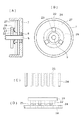
A ninth embodiment in which a slit is formed in the rotor core of the rotating electrical machine itself will be described with reference to FIGS. 10 and 11.
Main elements as a motor are denoted by the same reference numerals as those in FIGS. 1 and 2 and description thereof is omitted.
10 and 11, as shown in FIG. 10, as shown in FIG. 10, the permanent magnets N and S poles are alternately magnetized in the rotation direction in parallel with the rotation axis, as shown in FIG. 10. Yes.
The
The
The number of slits is not the number as described above, but corresponds to the number of phases and the number of main poles as a rotating electric machine, and the rotor position for determining the timing for supplying the excitation current to each coil is desired. It is only necessary to measure with high accuracy.
As shown in FIGS. 10 and 11, the
[0035]
In the above structure, when the rotating electrical machine is driven and the
Accordingly, when the slits a-1 to a-16 pass in front of the optical sensor, the rotational speed of the rotating electrical machine can be measured from the passing pitch, and when the slits b-1 to b-3 pass in front of the optical sensor. The timing at which each stator pole should be excited can be determined from the passage timing. When the slit C passes in front of the optical sensor, the corresponding predetermined stator pole, for example, the U-phase is fixed. The timing for exciting the child poles can be determined.
In the above description, the timing for exciting the V-phase stator pole can be determined from the passage of any of the slits b-1 to b-3 after the slit C passes, and the W-phase stator pole should be excited. The timing can be determined from the passage of any of the second slits b-1 to b-3 through which the slit C has passed.
[0036]
The arrangement of the slits shown in FIG. 10 is an example, and can be directly detected from a combination of a plurality of slits formed on the same diameter so that the position of each stator pole can be directly detected. Appropriately formed.
In addition, optical sensors corresponding to the same stator pole position are appropriately arranged on the same circumference in correspondence with the required detection accuracy of each stator pole position, and a plurality of detected signals are logically added, for example. For example, processing corresponding to the logic of the sensing system configuration may be performed.
In the above description, the light source and the light receiving element are made to correspond one-to-one, but it is natural that either or both may be made common so that they can be discriminated by optical processing.
[0037]
Embodiment 10:
Although the detailed illustration is omitted, a tenth embodiment using an optical sensor different from the ninth embodiment will be described.
That is, in the ninth embodiment, the example in which the rotor itself of the rotating electrical machine is formed on the rotation detection body has been described, but in this embodiment, as described in the third embodiment, Nr or Nr around the periphery. A disk formed with multiple gear-shaped small teeth is used as a rotation detection body, and the rotor is fixed to the rotating body via a predetermined air gap, and the light projecting function is sandwiched between the small teeth of the disk. A light receiving function is formed to form an optical sensor.
In the case of the present embodiment as well, not only small teeth are formed around the disk, but a slit may be appropriately formed to combine the small teeth and the slit, and the corresponding optical sensor may be configured. .
[0038]
Embodiment 11:
Next, an example of means for detecting the rotor position by the sensor configured as described in each of the above embodiments and supplying the exciting current to the corresponding phase circuit of the rotating electrical machine is described as an embodiment in which the coil is a sensor. This will be described with reference to FIGS.
FIG. 12 shows an example of a circuit configuration relating to a means for detecting the rotor position and supplying an exciting current to a corresponding phase circuit of the rotating electrical machine, and FIG. 13 shows an operation performed by the circuit shown in FIG. It is shown by a flow diagram with the horizontal axis as time.
In FIG. 12, 31U, 31V, and 31W are U-phase, V-phase, and W-phase coils configured as the sensors described above, respectively.
32a to 32c are transistors for the respective phases, 33a to 33c are first comparators for the respective phases, 34a to 34c are fixed resistors for the respective phases, and 35a to 35c are second resistors having functions to be described later.
[0039]
The
Accordingly, the
13A shows the inductance change value of the predetermined phase coil, FIG. 13B shows the chopping current it described above, and FIG. 13C shows the waveform shaping circuit not shown in FIG. The waveform of the chopping current Rt thus formed is measured in advance by a waveform shaping circuit (not shown) in the same figure (D), and the above-mentioned shaping chopping for obtaining the set optimum rotor position. The waveforms of constant-width pulses Rr having a frequency synchronized with the current Rt are shown.
[0040]
As shown in FIG. 13B, in each phase, the chopping current it changes corresponding to the inductance change shown in FIG.
That is, the coil inductance changes and the circuit time constant changes depending on the positional relationship between the coil and the magnetic teeth formed on the rotated body, and the chopping current waveform changes accordingly. Therefore, as shown in FIGS. 13C and 13D, the pulse width changes corresponding to the inductance value.
Therefore, the chopping current Rt converted from the chopping current it shown in FIG. 5C and the constant width pulse shown in FIG. 4D are used by the
Note that an alternating voltage or a chopping signal having a predetermined frequency may be applied to the coil, and a change in reactance accompanying a change in inductance of the coil may be detected by a change in amplitude or a phase shift.
The above is an example in which the inductance change of the coil is used as a sensor, and an arbitrary circuit may be set to achieve the object. For example, the chopping current it may be integrated.
Further, the means for using the magnetically sensitive element or the light receiving element as a sensor may be configured according to the above by applying a signal conversion circuit corresponding to each element, and the description thereof will be omitted.
[0041]
In the above description, a three-phase six-pole motor has been described as an object of the invention technology application. However, when a multi-pole motor such as a 100-pole motor is a target, the same means is appropriately applied to the structure of the rotating electrical machine. Applicable to.
In addition, corresponding to the structure of the multipolar motor, the type of sensor, the mounting structure, and the structure of the rotated detection body may be selected and set with reference to the appropriate embodiments from the various embodiments described above. Is natural.
[0042]
【The invention's effect】
Since the multiphase rotating electrical machine and the sensing method based on the present invention are configured and operated as described above, they have the following excellent effects.
(1) While simply configuring a magnetically sensitive element such as an inexpensive Hall element, a coil, or an optical sensor with a stator or a rotor part of the rotating electrical machine itself, or a similar structure that can utilize processing means, It can be used as a highly accurate sensor for closed-loop control of multipolar rotating electrical machines.
(2) If the sensor uses a magnetic detection function and the sensor stator is provided with pole teeth as an inductor, the rotor magnetic flux is guided to the pole teeth and collected to the magnetic sensing element or coil. Since the magnetic change can be detected by guiding, the desired measurement accuracy can be obtained without special consideration as the sensor mounting position accuracy.
(3) When the periphery of the sensor rotor is formed in a gear shape, an inexpensive magnetic iron plate may be used, and positioning with high stability that is hardly affected by temperature or the like can be achieved.
(4) When a slit is provided in the core of a cylindrical magnet type rotor and the rotor itself is used as a rotation detection body, a special sensor rotor is not used, and induction speed voltage may not be used. The rotor position can be detected with high accuracy from the start.
(5) When the inductance change of the coil is used as a sensor, the rotor position can be detected with a desired accuracy with a simple structure and configuration.
(6) When the means described in
[Brief description of the drawings]
BRIEF DESCRIPTION OF DRAWINGS FIG. 1 is a longitudinal front view of a rotating electrical machine for explaining Embodiments 1 and 2 of the present invention.
2 is a front view of a sensor stator and a sensor rotor for explaining the sensor system in the first and second embodiments shown in FIG. 1; FIG.
FIG. 3 is a cross-sectional view of a rotating electrical machine to which
FIG. 4 is a longitudinal front view of a rotating electrical machine for explaining
FIG. 5 is a front view of a sensor stator and a sensor rotor for explaining a sensor system according to
6A and 6B are explanatory diagrams for explaining the operation of the third embodiment. FIG. 6A is a diagram showing the relative positions of a U-phase sensor stator pole, a coil, and a sensor rotor, and FIG. (C) and (D) are diagrams showing changes in the coil inductances of the U phase, the V phase, and the W phase, respectively.
FIG. 7 is a longitudinal sectional front view for explaining a configuration of a sensor system for a rotating electrical machine according to a fifth embodiment of the present invention.
8A and 8B are diagrams for explaining a sixth embodiment of the present invention, in which FIG. 8A is a longitudinal front view of a rotating electric machine of the sixth embodiment, FIG. 8B is a front view of a sensor portion, and FIG. (C) is a development view of the sensor portion, and (D) is a side view of the sensor portion.
FIG. 9 is a longitudinal front view of a rotary electric machine for explaining an eighth embodiment of the present invention.
FIG. 10 is a cross-sectional view illustrating a sensor system according to Embodiment 9 of the present invention.
FIG. 11 is a longitudinal front view of a rotating electric machine for explaining a sensor system according to a ninth embodiment shown in FIG.
FIG. 12 is a block circuit diagram showing a circuit configuration for explaining a sensing system using a coil as a sensor according to an eleventh embodiment of the present invention.
13 is a time flow diagram showing a sensing function based on a block diagram for explaining the function of the eleventh embodiment shown in FIG. 12, wherein FIG. 13 (A) is an inductance change diagram of a predetermined phase coil, and FIG. FIG. 4C is a waveform diagram of the chopping current Rt, FIG. 4D is a waveform diagram of the shaped chopping current Rr, and FIG. 4E is a waveform diagram of the next phase excitation signal Pt.
FIG. 14 is a perspective view of a stator and a rotor of a rotating electrical machine for explaining an example of means for detecting rotor position information for a closed-loop controlled rotating electrical machine of a conventional example.
15 is a perspective view of a stator and a rotor of a rotating electric machine and an example for sensing, explaining another example of the means for detecting position information of the rotor for a closed-loop controlled rotating electric machine of a conventional example; FIG. It is the block diagram which wrote together with the block circuit diagram.
[Explanation of symbols]
1, 1A, 51: Stator
2, 52: Coil (winding)
3, 93: Rotor
4, 94: York
5, 55: Rotating shaft
6, 56: Output side cover
7, 57: Non-output side cover
8, 58: Bearing
9: Gear-like magnetic body for HB type rotor
10: Permanent magnet for HB type rotor
11, 15, 17, 61: Stator for sensor
11A, 15A: sensor stator poles
11a, 15a: pole teeth (inductor)
11b, 15b: York
12, 31U, 31V, 31W: Coil for sensor
13, 16, 18, 28, 63, 93: Sensor rotor (rotation detection object)
14: Rotor yoke for sensor
32: Transistor
33.35: Comparator
34: Fixed resistor
36: Driver
37U, 37V, 37W: Rotating electric machine excitation coil
97: Light emitting device
98: Light receiving element
a-1 to a-16, b-1 to b-3, C: slit
U1, U2, U3: Magnetic sensitive elements (Hall elements)
Claims (15)
該固定子の磁歯表面との間に所定のエアギャップを設けて、回転方向にNr個の磁歯を有するギヤ状の磁性体2個の間に軸方向に磁化した永久磁石を挟持したハイブリッド型回転子、又は、回転方向に各Nr個のN極、S極同数の永久磁石を交互に円筒状に形成した円筒状永久磁石形回転子を、回転自在に支承して設けた回転電機において、
略前記固定子に連結する環状の磁性体内面から円中心に向け求心状に等ピッチに当該回転電機を形成する相数又は相数の整数倍のセンサー用固定子極を配設し、
該センサー用固定子極の所定位置にセンサーを装着して先端部に誘導子を形成し、前記固定子に所定のエアギャップを介して構成したセンサー用固定子と、
該センサー用固定子極の誘導子との間に所定のエアギャップを設けて、回転軸に固定して回転方向に前記センサーに対応する被回転検出体を形成したことを特徴とする多極回転電機。A substantially pole-shaped magnetic body is arranged at an equal pitch from the inner surface of the magnetic body toward the center of the circle, and each of them is wound with a winding for excitation to form a main pole provided with a plurality of predetermined magnetic teeth at the tip 3 Phase stator,
A hybrid in which a predetermined air gap is provided between the magnetic tooth surfaces of the stator and a permanent magnet magnetized in the axial direction is sandwiched between two gear-like magnetic bodies having Nr magnetic teeth in the rotational direction. In a rotating electrical machine in which a cylindrical permanent magnet rotor in which Nr N poles and S poles of the same number of permanent magnets are alternately formed in a cylindrical shape is rotatably supported ,
A sensor stator pole having the number of phases or an integer multiple of the number of phases forming the rotating electrical machine at an equal pitch centripetally from the inner surface of the annular magnetic body connected to the stator to the center of the circle,
A sensor stator configured by attaching a sensor to a predetermined position of the sensor stator pole to form an inductor at a tip portion, and a predetermined air gap on the stator;
A multipolar rotation characterized in that a predetermined air gap is provided between the sensor stator pole inductor and the rotation detection body corresponding to the sensor in the rotation direction by being fixed to a rotating shaft. Electric.
当該回転電機の固定子に連結する環状の磁性体内面から円中心に向け求心状に等ピッチに当該回転電機を形成する相数又は相数の整数倍のセンサー用固定子極を配設し、
該センサー用固定子極夫々の所定位置にセンサーとして磁気感応素子を装着して先端部に誘導子を形成し、前記固定子に所定のエアギャップを介して構成したセンサー用固定子と、
該センサー用固定子の誘導子に対応し所定のエアギャップを介して、当該回転電機の回転子と同軸上にNr又はNrの整数倍の磁歯を有するギヤ状の磁性体2個の間に軸方向に磁化した永久磁石を挟持したセンサー用ハイブリッド型回転子、
又は当該回転電機の回転子と同軸上に極対数がNr個又はNrの整数倍個のN極、S極同数の永久磁石を交互に円筒状に形成したセンサー用永久磁石形回転子によって前記被回転検出体を形成し、上記磁気感応素子がセンサー用回転子に形成した磁極を検知することにより回転子の位置を検知するように形成したことを特徴とする多極回転電機。
但し、Nr=m(3n±1)、又は、
Nr=m(6n±1)/2
また、m≧2の整数、n≧1の整数である。The rotating electrical machine according to claim 1, wherein
A sensor stator pole having the number of phases or an integer multiple of the number of phases forming the rotating electrical machine at an equal pitch centripetally from the inner surface of the annular magnetic body connected to the stator of the rotating electrical machine toward the center of the circle,
A sensor stator configured by attaching a magnetic sensing element as a sensor at a predetermined position of each of the sensor stator poles to form an inductor at a tip portion, and a predetermined air gap in the stator,
Corresponding to the inductor of the sensor stator via a predetermined air gap, between two gear-like magnetic bodies having magnetic teeth Nr or an integral multiple of Nr coaxially with the rotor of the rotating electrical machine. A hybrid rotor for sensors with a permanent magnet magnetized in the axial direction,
Alternatively, the sensor permanent magnet rotor may be formed by alternately forming Nr and S poles of the same number of pole magnets on the same axis as the rotor of the rotating electrical machine in a cylindrical shape. A multipolar rotating electric machine characterized by forming a rotation detecting body and detecting the position of the rotor by detecting the magnetic pole formed by the magnetically sensitive element on the sensor rotor.
However, Nr = m ( 3 n ± 1), or
Nr = m ( 6 n ± 1) / 2
Further, m ≧ 2 integers and integers n ≧ 1.
当該回転電機の固定子に連結する環状の磁性体内面から円中心に向け求心状に等ピッチに当該回転電機を形成する相数又は相数の整数倍のセンサー用固定子極を配設し、
該センサー用固定子極夫々の所定位置にセンサーとしてコイルを巻装して先端部に誘導子を形成し、前記固定子に平行に所定のエアギャップを介して構成したセンサー用固定子と、
該センサー用固定子の誘導子に対応し所定のエアギャップを介して、当該回転電機の回転子と同軸上にNr又はNrの整数倍の磁歯を有するギヤ状の磁性体で形成したセンサー用回転子によって前記被回転検出体を形成し、
上記コイルのインダクタンスがセンサー用回転子に形成した磁歯の有無によって変化することにより回転子の位置を検知するようにしたことを特徴とする多極回転電機。
但し、Nr=m(3n±1)、又は、
Nr=m(6n±1)/2
また、m≧2の整数、n≧1の整数である。The rotating electrical machine according to claim 1, wherein
A sensor stator pole having the number of phases or an integer multiple of the number of phases forming the rotating electrical machine at an equal pitch centripetally from the inner surface of the annular magnetic body connected to the stator of the rotating electrical machine toward the center of the circle,
A sensor stator formed by winding a coil as a sensor at a predetermined position of each of the sensor stator poles to form an inductor at the tip, and a predetermined air gap parallel to the stator,
For a sensor formed of a gear-like magnetic body having a magnetic tooth Nr or an integral multiple of Nr coaxially with the rotor of the rotating electrical machine via a predetermined air gap corresponding to the inductor of the sensor stator The rotor to be detected is formed by a rotor,
A multipolar rotating electrical machine characterized by detecting the position of a rotor by changing the inductance of the coil depending on the presence or absence of magnetic teeth formed in a sensor rotor.
However, Nr = m ( 3 n ± 1), or
Nr = m ( 6 n ± 1) / 2
Further, m ≧ 2 integers and integers n ≧ 1.
センサー用固定子極数を2または2の倍数とし、上記センサー用コイルの出力信号が相互に電気角で90度の位相差を有するように形成したことを特徴とする多極回転電機。In the rotating electrical machine according to claim 3,
Se stator pole number for Nsa and 2 or a multiple of two, multipolar rotary electric machine, wherein the output signal of the coil the sensor is formed to have a phase difference of 90 degrees in electrical angle from each other.
当該回転電機に形成するセンサー用固定子極は、当該多極回転電機の固定子に形成する磁極と磁極位置を対応させると共に、被回転検出体に形成した磁極対数又は磁歯数に対応させて、複数所定個の誘導子を形成する磁歯を各所定個、等ピッチで設けたことを特徴とする多極回転電機。The rotating electrical machine according to any one of claims 1 to 4,
The sensor stator poles formed on the rotating electrical machine correspond to the magnetic poles and magnetic pole positions formed on the stator of the multipolar rotating electrical machine, and correspond to the number of magnetic pole pairs or the number of magnetic teeth formed on the rotation detection body. A multipolar rotating electrical machine characterized in that a plurality of predetermined number of magnetic teeth forming a predetermined number of inductors are provided at equal pitches.
当該回転電機に形成するセンサー用固定子極先端の誘導子と、回転軸に固定した被回転検出体とは所定のエアギャップを介して同一円周上で相互に対向させて形成させたことを特徴とする多極回転電機。In the rotating electrical machine according to any one of claims 1 to 5,
The inductor at the tip of the sensor stator pole formed on the rotating electrical machine and the rotation detection body fixed to the rotating shaft are formed to face each other on the same circumference via a predetermined air gap. A multi-pole rotating electrical machine.
当該回転電機に形成するセンサー用固定子極先端の誘導子と、
回転軸に固定した被回転検出体とは夫々の側面を所定のエアギャップを介して相互に対面させて形成させたことを特徴とする多極回転電機。In the rotating electrical machine according to any one of claims 1 to 5,
An inductor at the tip of a stator pole for a sensor formed in the rotating electrical machine;
A multipolar rotating electrical machine characterized in that a rotation detection body fixed to a rotating shaft is formed such that each side face faces each other through a predetermined air gap.
当該回転電機の回転子に形成した円筒状永久磁石と回転軸との間に形成した中子にNr個又はNrに比例する個数の所定形状のスリットを設けて該中子を被回転検出体とし、
当該回転電機を形成する相数又は相数の整数倍のセンサー用固定子極を上記被回転検出体に対して所定のエアギャップを介して対面するように配設し、
該センサー用固定子極夫々の端面所定位置に上記スリットに対応した形状の複数所定個の誘導子を形成する磁歯を形成し、この磁歯群にコイルを巻装して誘導子を形成し、該コイルのインダクタンスがセンサー用回転子に形成したスリットの有無によって変化することにより回転子の位置を検知するようにしたことを特徴とする多極回転電機。
但し、Nr=m(3n±1)、又は、
Nr=m(6n±1)/2
また、m≧2の整数、n≧1の整数である。The rotating electrical machine according to claim 1, wherein
The core formed between the cylindrical permanent magnet formed on the rotor of the rotating electrical machine and the rotating shaft is provided with Nr pieces or slits of a predetermined shape in proportion to Nr, and the core is used as a rotation detection body. ,
The number of phases forming the rotating electric machine or an integer multiple of the number of phases is arranged so as to face the rotation detection body through a predetermined air gap,
Magnetic teeth forming a plurality of predetermined inductors having shapes corresponding to the slits are formed at predetermined positions on the end surfaces of the sensor stator poles, and coils are wound around the magnetic tooth groups to form inductors. The multipolar rotating electric machine is characterized in that the position of the rotor is detected by changing the inductance of the coil depending on the presence or absence of a slit formed in the sensor rotor.
However, Nr = m ( 3 n ± 1), or
Nr = m ( 6 n ± 1) / 2
Further, m ≧ 2 integers and integers n ≧ 1.
回転子に形成される磁極と、
センサー用回転子に形成される磁極又は磁歯の回転子磁極又は磁歯からの回転子方向の位置偏位をθr、任意の相の固定子主極に形成する磁歯とセンサー用固定子の対応する誘導子を形成する磁歯との回転子回転方向の位置偏位をθsとし、下式を満足するように形成したことを特徴とする多極回転電機。
但し、0≦θr≦360/Nr
0≦θs≦120/Nr
また、Nrは回転子極対数
θr=0のときは、θs≠0
θs=0のときは、θr≠0である。In the multipolar rotating electrical machine according to any one of claims 1 to 8,
Magnetic poles formed on the rotor;
The position deviation in the rotor direction from the magnetic pole or magnetic tooth of the magnetic pole or magnetic tooth formed on the sensor rotor is θr, and the magnetic tooth formed on the stator main pole of an arbitrary phase and the sensor stator A multipolar rotating electrical machine characterized in that the position deviation in the rotor rotation direction with respect to the magnetic teeth forming the corresponding inductor is θs, and the following formula is satisfied.
However, 0 ≦ θr ≦ 360 / Nr
0 ≦ θs ≦ 120 / Nr
Nr is θs ≠ 0 when the number of rotor pole pairs θr = 0.
When θs = 0, θr ≠ 0.
当該回転電機の回転子の外径をD1、当該回転電機の反出力軸側軸受の外径をD2、センサー用回転子の外径をD3とし、該D1、D2、D3を下式を満足するように形成して、
センサー用固定子とセンサー用回転子の対を当該回転電機の反出力軸側軸受の外部に形成したことを特徴とする多極回転電機。
D1>D2>D3The rotating electrical machine according to any one of claims 1 to 7 or 9,
The outer diameter of the rotor of the rotating electric machine is D1, the outer diameter of the non-output shaft side bearing of the rotating electric machine is D2, the outer diameter of the rotor for the sensor is D3, and D1, D2, and D3 satisfy the following equations. Formed as
A multipolar rotating electrical machine characterized in that a pair of a sensor stator and a sensor rotor is formed outside a non-output shaft side bearing of the rotating electrical machine.
D1>D2> D3
当該回転電機の回転子の外径をD1、当該回転電機の反出力軸側軸受装着孔の内径をD2′、センサー用回転子の外径をD3とし、該D1、D2′、D3を下式を満足するように形成して、センサー用固定子とセンサー用回転子の対を当該回転電機の反出力軸側軸受の外部に形成したことを特徴とする多極回転電機。
D1>D2′>D3The rotating electrical machine according to any one of claims 1 to 7 or 9,
The outer diameter of the rotor of the rotating electric machine is D1, the inner diameter of the non-output shaft side bearing mounting hole of the rotating electric machine is D2 ', the outer diameter of the rotor for the sensor is D3, and D1, D2' and D3 are And a pair of sensor stator and sensor rotor is formed outside the non-output shaft side bearing of the rotating electrical machine.
D1> D2 ′> D3
該固定子の磁歯表面との間に所定のエアギャップを設けて、回転方向にNr個の磁歯を有するギヤ状の磁性体2個の間に軸方向に磁化した永久磁石を挟持したハイブリッド型回転子、又は、回転方向に各Nr個のN極、S極同数の永久磁石を交互に円筒状に形成した円筒状永久磁石形回転子を、回転自在に支承して設けた回転電機において、
上記回転子を軸方向に同心的に貫通するNr個又はNrに比例する個数のスリット部を形成するか、
又は、回転方向にNr個又はNrに比例する個数の小歯を有するギヤ状の回転体を形成して被回転検出体を形成し、
上記スリット又は小歯の間隙を貫通し、上記固定子に形成する主極に対応する位置に光センサーを設け、該光センサーによる前記スリット位置を検出するようにしたことを特徴とする多極回転電機。
但し、Nr=m(3n±1)、又は、
Nr=m(6n±1)/2
また、m≧2の整数、n≧1の整数である。A substantially pole-shaped magnetic body is arranged at an equal pitch from the inner surface of the magnetic body toward the center of the circle at an equal pitch, each of which is wound with a winding for excitation, and a plurality of predetermined magnetic teeth are provided at the tip to form a main pole 3 Phase stator,
A hybrid in which a predetermined air gap is provided between the magnetic tooth surfaces of the stator and a permanent magnet magnetized in the axial direction is sandwiched between two gear-like magnetic bodies having Nr magnetic teeth in the rotational direction. In a rotating electrical machine in which a cylindrical permanent magnet rotor in which Nr N poles and S poles of the same number of permanent magnets are alternately formed in a cylindrical shape is rotatably supported ,
Forming Nr pieces that are concentrically penetrating the rotor in the axial direction or a number of slit portions proportional to Nr;
Alternatively, a rotation detection body is formed by forming a gear-like rotation body having Nr pieces or a number of small teeth proportional to Nr in the rotation direction,
A multipolar rotation characterized in that an optical sensor is provided at a position corresponding to the main pole formed in the stator through the slit or small tooth gap, and the slit position is detected by the optical sensor. Electric.
However, Nr = m ( 3 n ± 1), or
Nr = m ( 6 n ± 1) / 2
Further, m ≧ 2 integers and integers n ≧ 1.
該センサー用コイルをチョッピング回路に形成し、
センサー用コイルインダクタンスの変化によるチョッピング周期又はデユテイの変化を検知して回転子の位置情報を得るようにしたことを特徴とする多極回転電機のセンシング方法。In the rotating electrical machine in which the coil according to any one of claims 1 or 3 to 11 is formed as a sensor,
Forming the sensor coil in a chopping circuit;
A sensing method for a multipolar rotating electrical machine, wherein a change in chopping period or duty due to a change in sensor coil inductance is detected to obtain rotor position information.
該センサー用コイルに交番電圧を供給し、コイルインダクタンス変化による電流値の変化を検知することによって回転子の位置情報を得るようにしたことを特徴とする多極回転電機のセンシング方法。In the rotating electrical machine in which the coil according to any one of claims 1 or 3 to 11 is formed as a sensor,
A sensing method for a multipolar rotating electrical machine, wherein an alternating voltage is supplied to the sensor coil, and a change in current value due to a change in coil inductance is detected to obtain rotor position information.
該磁気感応素子にホール素子を使用したことを特徴とする多極回転電機のセンシング方法。In a rotating electrical machine in which the magnetically sensitive element according to any one of claims 1 to 2 or 5 to 11 is formed as a sensor,
A sensing method for a multipolar rotating electrical machine, wherein a Hall element is used as the magnetically sensitive element.
Priority Applications (1)
| Application Number | Priority Date | Filing Date | Title |
|---|---|---|---|
| JP19580899A JP4150133B2 (en) | 1999-07-09 | 1999-07-09 | Multipolar rotating electrical machine and its sensing method |
Applications Claiming Priority (1)
| Application Number | Priority Date | Filing Date | Title |
|---|---|---|---|
| JP19580899A JP4150133B2 (en) | 1999-07-09 | 1999-07-09 | Multipolar rotating electrical machine and its sensing method |
Publications (3)
| Publication Number | Publication Date |
|---|---|
| JP2001025212A JP2001025212A (en) | 2001-01-26 |
| JP2001025212A5 JP2001025212A5 (en) | 2005-09-29 |
| JP4150133B2 true JP4150133B2 (en) | 2008-09-17 |
Family
ID=16347337
Family Applications (1)
| Application Number | Title | Priority Date | Filing Date |
|---|---|---|---|
| JP19580899A Expired - Fee Related JP4150133B2 (en) | 1999-07-09 | 1999-07-09 | Multipolar rotating electrical machine and its sensing method |
Country Status (1)
| Country | Link |
|---|---|
| JP (1) | JP4150133B2 (en) |
Cited By (1)
| Publication number | Priority date | Publication date | Assignee | Title |
|---|---|---|---|---|
| FR3114454A1 (en) * | 2020-09-22 | 2022-03-25 | Ntn-Snr Roulements | N-phase electrical machine |
Families Citing this family (4)
| Publication number | Priority date | Publication date | Assignee | Title |
|---|---|---|---|---|
| JP4038664B2 (en) * | 2002-06-05 | 2008-01-30 | ミネベア株式会社 | Stepping motor |
| JP2014099968A (en) * | 2012-11-13 | 2014-05-29 | Nidec Sankyo Corp | Motor and motor inspection method |
| KR101987169B1 (en) * | 2012-12-17 | 2019-06-10 | 엘지이노텍 주식회사 | Motor |
| DE102014216367A1 (en) * | 2014-08-18 | 2016-02-18 | Robert Bosch Gmbh | Electric machine with integrated encoder structure |
Family Cites Families (7)
| Publication number | Priority date | Publication date | Assignee | Title |
|---|---|---|---|---|
| JPS62107584U (en) * | 1985-12-26 | 1987-07-09 | ||
| JPH0635656Y2 (en) * | 1987-08-07 | 1994-09-14 | 山洋電気株式会社 | Stepping motor |
| JPH01180181U (en) * | 1988-06-06 | 1989-12-25 | ||
| JP2933792B2 (en) * | 1993-01-15 | 1999-08-16 | 株式会社三協精機製作所 | Rotating electric machine |
| JP3136921B2 (en) * | 1993-10-27 | 2001-02-19 | 松下電器産業株式会社 | Magnetic sensor and motor with magnetic sensor |
| JP4050359B2 (en) * | 1997-06-13 | 2008-02-20 | オリエンタルモーター株式会社 | Motor with built-in sensor |
| JPH1155902A (en) * | 1997-07-30 | 1999-02-26 | Oriental Motor Co Ltd | Structure of sensor built-in motor |
-
1999
- 1999-07-09 JP JP19580899A patent/JP4150133B2/en not_active Expired - Fee Related
Cited By (2)
| Publication number | Priority date | Publication date | Assignee | Title |
|---|---|---|---|---|
| FR3114454A1 (en) * | 2020-09-22 | 2022-03-25 | Ntn-Snr Roulements | N-phase electrical machine |
| WO2022063772A1 (en) * | 2020-09-22 | 2022-03-31 | Ntn-Snr Roulements | N-phase electric machine |
Also Published As
| Publication number | Publication date |
|---|---|
| JP2001025212A (en) | 2001-01-26 |
Similar Documents
| Publication | Publication Date | Title |
|---|---|---|
| US4529900A (en) | Brushless motor | |
| JP4113339B2 (en) | Three-phase annular coil permanent magnet type rotating electrical machine | |
| US6552453B2 (en) | Magnetic pole position detector for an electric motor | |
| JP4592435B2 (en) | Small motor with encoder | |
| US9929629B2 (en) | Rotating electrical machine | |
| JP4103018B2 (en) | Servomotor | |
| EP0174290B1 (en) | Magnetic structure for synchro and tachometer | |
| KR20180022594A (en) | Electronically commutated electric motor with two rotor cores | |
| US5990651A (en) | Stepping motor drive apparatus and stepping motor | |
| KR20220047181A (en) | Magnetic sensor system for motor control | |
| JP4150133B2 (en) | Multipolar rotating electrical machine and its sensing method | |
| US4701650A (en) | Brushless motor with phase cancelling leads for rotational speed detector pattern | |
| JPS5855747B2 (en) | Brushless rotary motor | |
| JP2000092805A (en) | Servo motor | |
| KR20070113730A (en) | Switched reluctance motor | |
| JPH0727823Y2 (en) | Servostepping motor with position sensing element | |
| JP2021122171A (en) | Stepping motor | |
| JPS6028760A (en) | Reversible brushless motor without position detector with magnetic encoder | |
| JP3797488B2 (en) | Multi-pole rotating electric machine | |
| JP2516670Y2 (en) | Servostepping motor with position sensing element | |
| JP5452530B2 (en) | Magnetic inductor type rotary motor | |
| JP2001078392A (en) | Stepping motor with sensor | |
| JP2002186236A (en) | Magnetic pole position detecting device of motor | |
| JP3395147B2 (en) | Magnetic pole position detector | |
| JPS62166760A (en) | Dc brushless motor with built-in magnetic encoder |
Legal Events
| Date | Code | Title | Description |
|---|---|---|---|
| A521 | Request for written amendment filed |
Free format text: JAPANESE INTERMEDIATE CODE: A523 Effective date: 20050422 |
|
| A621 | Written request for application examination |
Free format text: JAPANESE INTERMEDIATE CODE: A621 Effective date: 20050422 |
|
| A977 | Report on retrieval |
Free format text: JAPANESE INTERMEDIATE CODE: A971007 Effective date: 20080208 |
|
| A131 | Notification of reasons for refusal |
Free format text: JAPANESE INTERMEDIATE CODE: A131 Effective date: 20080226 |
|
| A521 | Request for written amendment filed |
Free format text: JAPANESE INTERMEDIATE CODE: A523 Effective date: 20080424 |
|
| TRDD | Decision of grant or rejection written | ||
| A01 | Written decision to grant a patent or to grant a registration (utility model) |
Free format text: JAPANESE INTERMEDIATE CODE: A01 Effective date: 20080624 |
|
| A01 | Written decision to grant a patent or to grant a registration (utility model) |
Free format text: JAPANESE INTERMEDIATE CODE: A01 |
|
| A61 | First payment of annual fees (during grant procedure) |
Free format text: JAPANESE INTERMEDIATE CODE: A61 Effective date: 20080627 |
|
| FPAY | Renewal fee payment (event date is renewal date of database) |
Free format text: PAYMENT UNTIL: 20110704 Year of fee payment: 3 |
|
| R150 | Certificate of patent or registration of utility model |
Free format text: JAPANESE INTERMEDIATE CODE: R150 |
|
| FPAY | Renewal fee payment (event date is renewal date of database) |
Free format text: PAYMENT UNTIL: 20110704 Year of fee payment: 3 |
|
| S531 | Written request for registration of change of domicile |
Free format text: JAPANESE INTERMEDIATE CODE: R313531 |
|
| S533 | Written request for registration of change of name |
Free format text: JAPANESE INTERMEDIATE CODE: R313533 |
|
| LAPS | Cancellation because of no payment of annual fees | ||
| R350 | Written notification of registration of transfer |
Free format text: JAPANESE INTERMEDIATE CODE: R350 |