JP4148376B2 - Pushbutton switch with display - Google Patents
Pushbutton switch with display Download PDFInfo
- Publication number
- JP4148376B2 JP4148376B2 JP27700998A JP27700998A JP4148376B2 JP 4148376 B2 JP4148376 B2 JP 4148376B2 JP 27700998 A JP27700998 A JP 27700998A JP 27700998 A JP27700998 A JP 27700998A JP 4148376 B2 JP4148376 B2 JP 4148376B2
- Authority
- JP
- Japan
- Prior art keywords
- guide plate
- light guide
- light
- display device
- pushbutton switch
- Prior art date
- Legal status (The legal status is an assumption and is not a legal conclusion. Google has not performed a legal analysis and makes no representation as to the accuracy of the status listed.)
- Expired - Fee Related
Links
Images


Landscapes
- Push-Button Switches (AREA)
Description
【0001】
【発明の属する技術分野】
本発明は、操作用ボタンに液晶表示を備えた表示装置付き押ボタンスイッチに関し、薄型でコンパクトに構成することができ、均一で鮮明な表示を可能にしたバックライト装置を有した表示装置付き押ボタンスイッチに関する。
【0002】
【従来の技術】
従来、液晶表示を備えた表示装置付き押ボタンスイッチは、図3に示すように多チップ搭載型の発光ダイオード129を左右又は前後に配列するとともに、発光ダイオードの点発光を拡散させるための拡散スペースを確保したデフューザ126を配設している。また、白色発光型液晶表示装置のバックライトにおいては蛍光管等が使用されている。
【0003】
【発明が解決しようとする課題】
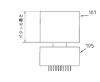
従来の液晶表示を備えた表示装置付き押ボタンスイッチは、多チップ搭載型の発光ダイオード129を配設しているため高価であった。また、均一に発光させるためには拡散スペースを十分に確保する必要があることから、ボタン121の幅が図3に示すように大きくなるという欠点を有していた。また、蛍光管等を利用したものはバックライト部が大きくなるため、図4に示すようにボタン161の高さが大きくなるという欠点があった。
また、最近の技術革新により、極めて輝度の高い白色発光ダイオード等が提供されているが、カスタム化されて広く利用されるまでには至ってなく、比較的安価な既製の高輝度型チップダイオードを利用して省スペース化と均一な照光を実現する必要があった。
本発明は、上記課題を解決し、省スペース化のために高輝度発光ダイオードの光源を液晶表示部の直下に配設しても均一な照光を得ることができる表示装置付き押ボタンスイッチを提供するものである。
【0004】
【課題を解決するための手段】
本発明は上記の問題点を解決するために、操作用のボタン上面に液晶表示を備えた表示装置付き押ボタンスイッチにおいて、前記ボタンに内接するホルダを設けるとともに、少なくとも一方に凹所を形成した透光性部材からなる導光板を前記ホルダに配設し、しかも発光素子を略水平に向けて前記凹所に配設するとともに、前記導光板を第1の導光板と第2の導光板からなる2層構造とし前記第1の導光板上に少なくとも片側に舌片を形成した第2の導光板を載置するとともに該第2の導光板を上方に向けて一方向のみ透光性を有した拡散板とし該拡散板の前記舌片を折返すことによって、前記発光素子の少なくとも上面に遮光部を形成するように構成したものである。
【0005】
【発明の実施の形態】
本発明の表示装置付き押ボタンスイッチの液晶用バックライトに既製の高輝度型単一発光ダイオード素子を利用することが可能となり、鮮明で均一な表示を可能とした小形の液晶表示付き押ボタンスイッチを安価に提供することができる。
【0006】
【実施例】
以下、本発明の実施例を図面を参照しながら詳細に説明する。
図1は本発明の表示装置付き押ボタンスイッチの実施例を表す正面断面図であり、図2はその分解斜視図である。
これらの図において、箱形のボタン81の上面に矩形状で透明な表示窓82を設けて表示部を形成し、このボタン81内より表示窓82に接して液晶板84が配設される。
【0007】
液晶板84の下方には、透明部材の第1の導光板86aと一方からの光のみを透過し反対方向の光を遮断する指向性を持つ拡散シートからなる第2の導光板86bとの2層構造を成す透光性部材からなる導光板と、この導光板の一方の下側にバックライト用の発光ダイオード89が発光方向を水平に向けて配設され、その上部に発光ダイオード89の光源を遮光するために前記第2の導光板86bの一方に形成した舌片88を折り畳んで遮光部を形成する。前記第1の導光板86aには凹所87が形成されて発光ダイオード89を収納するように構成されている。
【0008】
発光ダイオード89は輝度の高い白色ダイオード等で、側面に端子90を形成した面実装型であり、弾性接触片を有した一対の固定接片91を後述のホルダ99に配設するとともにこの固定接片91間に発光ダイオード89を圧入配設する。
【0009】
前述の液晶板84と第1の導光板86a及び第2の導光板86bと発光ダイオード89さらに固定接片91は箱形のホルダ99によりボタン81内に配設されている。
そして回路パターンを形成してIC部13を搭載したプリント基板12が前記ホルダ99の下方に配設されるとともにホルダ99の側壁に沿って貫通した矩形孔が形成され、インターコネクタ5が挿入される。このインターコネクタ5の両端は液晶板84の鍔面とプリント基板12のコネクタ部18に当接して上下のみ方向性をもって電気的に接続する。
【0010】
そしてプリント基板12の下面には、上面とスルーホールにより接続された回路パターンが形成され、フレキシブルプリント基板14のコネクタ部16とはんだ付けにより接続されている。
【0011】
フレキシブルプリント基板14は、後述するプランジャ25の上方に突出する嵌合部26とオサエ板20から垂下する円筒部を遊嵌するための穴部15を形成しており、プリント基板12に接続したフレキシブルプリント基板14をホルダ99の下面とオサエ板20の上面の周囲でフレキシブルプリント基板14を挟持しながら反転させ、オサエ板20から垂下する円筒部を穴部15に遊嵌してコネクタ部18を側面に導出するように取付けた後、オサエ板20に対向形成された凸部21をボタン81に形成した角孔83に凹凸関係により嵌着して、液晶表示装置を構成する。
【0012】
スイッチ本体の外郭を構成するケース35には、コネクタ33とN/Oスイッチ素子30とN/Cスイッチ素子31及び操作バランスを保つための板バネ28が組込まれ、このコネクタ33に上記したフレキシブルプリント基板14の一端のコネクタ部17が挿入接続される。更に、各スイッチ素子の接点を駆動するための作動部27を形成したプランジャ25を組入れた後カバー22をケース35の凸部36に角孔24を凹凸嵌合させてスイッチ本体を構成し、前記オサエ板20から垂下する円筒部と前記プランジャ25から上方に突出する嵌合部26を嵌合させ本発明の表示装置付き押ボタンスイッチを構成する。
【0013】
以上のように構成された本発明の表示装置付き押ボタンスイッチは、発光ダイオード89が液晶板84の直下にあるにも拘わらず発光光源が第2の導光板86bの一方に形成し た舌片88を折り畳んで形成した遮光部で覆われるとともに導光板を透明部材の第1の導光板86aと一方からの光のみを透過し反対方向の光を遮断する指向性を持つ拡散シートからなる第2の導光板86bとの2層構造で構成しているので、表示窓側からの映像に発光光源が強く強調されることがないだけでなく、第2の導光板86bの光拡散効果により、舌片88を折り畳んで形成した遮光部自体の影も発生しないため、ムラの無い均一で鮮明な液晶表示装置付き押ボタンスイッチを構成することができる。
【0014】
また、発光ダイオード89の拡散スペースを最小限に止めることができるため、省スペースの液晶表示装置付き押ボタンスイッチを得ることができるとともに、安価な高輝度型チップダイオードを利用することにより、コストを削減することも可能である。
【0015】
さらに、面実装チップ型の発光ダイオード89を固定接片間に圧入配設できるように構成したので、組立てだけでなく、発光ダイオード89の交換も可能にし、メンテナンスが容易になるとともに部品在庫の削減をも実現することができる効果を生む。
【0016】
以上のように導光板を分割して構成したので、光路を水平面に拡散する機能と表示窓82方向に拡散する機能をそれぞれの導光板86a、86bが果たすため、一層均一で明るいバックライトを構成することができるとともに遮光部が影になり難く極めて簡単に遮光部を形成することができ、さらに遮光部の加工が容易になるなど加工方法の応用も可能となる。
【0017】
【発明の効果】
以上、詳細に説明したように、本発明によれば、次のような効果を奏することができる。
(1)操作用のボタン上面に液晶表示を備えた表示装置付き押ボタンスイッチにおいて、前記ボタンに内接するホルダを設けるとともに、少なくとも一方に凹所を形成した透光性部材からなる導光板を前記ホルダに配設し、しかも発光素子を略水平に向けて前記凹所に配設したので、液晶表示窓の縁取りが小さく、ボタンの厚さも薄い、デザインの良い表示装置付き押ボタンスイッチを構成することができる。
(2)凹所を形成した透光性部材からなる導光板をホルダに配設し、しかも発光素子を略水平に向けて前記凹所に配設するとともに発光素子の少なくとも上面に遮光部を形成したので、光源が目立たない均一な照光の表示装置付き押ボタンスイッチを構成することができる。
(3)導光板を第1の導光板と第2の導光板からなる2層構造とし、前記第1の導光板と前記第2の導光板の間に発光素子の少なくとも上面に遮光部を形成したので、光源が目立たず、遮光部上面に反射光が干渉するため、遮光部が影にならない鮮明な表示装置付き押ボタンスイッチを提供することができる。
(4)第1の導光板上に少なくとも片側に舌片を形成した第2の導光板を載置するとともに、該第2の導光板を上方に向けて一方向のみ透光性を有した拡散板とし、該拡散板の前記舌片を折返すことによって遮光部を形成したので、部品点数や加工工程を増やすことなく遮光部の形成が極めて簡単にできる。
(5)両側に端子を折り曲げた面実装型発光ダイオードを圧入固定するとともに前記端子と接触する固定接片を配設したので、発光ダイオードの組立や交換が容易な表示装置付き押ボタンスイッチを提供することができる。
(6)両側に端子を折り曲げた面実装型発光ダイオードを圧入固定するとともに前記端子と接触する固定接片を配設したので、発光色の対応が容易であり、組立部品の在庫を低減することができる。
【図面の簡単な説明】
【図1】 本発明の表示装置付き押ボタンスイッチの実施例を表す正面断面図である。
【図2】 本発明の表示装置付き押ボタンスイッチの実施例を表す分解斜視図である。
【図3】 従来の表示装置付き押ボタンスイッチの要部分解斜視図である。
【図4】 従来の表示装置付き押ボタンスイッチの正面図である。
【符号の説明】
81、121、161 ボタン
82、122 表示窓
24、83、123 角孔
84、124 液晶板
5 インターコネクタ
87 凹所
89、129 発光ダイオード
90、130 端子
91 固定接片
12 プリント基板
13 IC部
14 フレキシブルプリント基板
15、23 穴部
16、17、18 コネクタ部
99、139 ホルダ
20 オサエ板
21、36 凸部
22 カバー
25 プランジャ
26 嵌合部
27 作動部
28 板バネ
29 コイルバネ
30 N/Oスイッチ素子
31 N/Cスイッチ素子
32 スイッチ端子
33 コネクタ
34 コネクタ端子
35、195 ケース
86a 第1の導光板
86b 第2の導光板
88 舌片
126 デフューザ[0001]
BACKGROUND OF THE INVENTION
The present invention relates to a pushbutton switch with a display device having a liquid crystal display as an operation button. The pushbutton switch with a display device having a backlight device that can be configured thinly and compactly and enables uniform and clear display. It relates to button switches.
[0002]
[Prior art]
2. Description of the Related Art Conventionally, a pushbutton switch with a display device equipped with a liquid crystal display has a multi-chip mounting type
[0003]
[Problems to be solved by the invention]
A conventional pushbutton switch with a display device equipped with a liquid crystal display is expensive because a multi-chip mounted
In addition, recent technological innovations have provided white LEDs and other devices with extremely high brightness. However, they have not yet been customized and widely used, and use relatively inexpensive off-the-shelf high-brightness chip diodes. Therefore, it was necessary to realize space saving and uniform illumination.
The present invention provides a pushbutton switch with a display device that solves the above-described problems and can obtain uniform illumination even when a light source of a high-intensity light-emitting diode is disposed immediately below a liquid crystal display unit in order to save space. To do.
[0004]
[Means for Solving the Problems]
In order to solve the above problems, the present invention provides a pushbutton switch with a display device having a liquid crystal display on the upper surface of an operation button, and a holder inscribed in the button is provided, and a recess is formed in at least one of the buttons. the light guide plate made of light-transmissive member disposed on the holder, yet with towards substantially horizontally a light emitting element disposed in said recess, said light guide plate from the first light guide plate and the second light guide plate A second light guide plate having a tongue layer formed on at least one side is placed on the first light guide plate, and the second light guide plate faces upward and has translucency in only one direction. A light-shielding portion is formed on at least the upper surface of the light-emitting element by folding the tongue piece of the diffusion plate.
[0005]
DETAILED DESCRIPTION OF THE INVENTION
A small-sized pushbutton switch with a liquid crystal display which can use a ready-made high-brightness single light emitting diode element for the backlight for the liquid crystal of the pushbutton switch with a display device of the present invention, and enables a clear and uniform display. Can be provided at low cost.
[0006]
【Example】
Hereinafter, embodiments of the present invention will be described in detail with reference to the drawings.
FIG. 1 is a front sectional view showing an embodiment of a pushbutton switch with a display device of the present invention, and FIG. 2 is an exploded perspective view thereof .
In these drawings, a rectangular and
[0007]
Below the
[0008]
[0009]
The rectangular hole printed
[0010]
A circuit pattern connected to the upper surface by a through hole is formed on the lower surface of the printed
[0011]
The flexible printed
[0012]
A
[0013]
The display device with push-button switch of the present invention configured as described above, the tongue of the
[0014]
Further, since the diffusion space of the light-emitting
[0015]
Further, since the configuration can be pressed disposed a
[0016]
Since the light guide plate is divided as described above, the
[0017]
【The invention's effect】
As described above in detail, according to the present invention, the following effects can be obtained.
(1) In a pushbutton switch with a display device provided with a liquid crystal display on the upper surface of an operation button, a light guide plate made of a translucent member provided with a holder inscribed in the button and having a recess formed in at least one of the buttons is provided. Since the light emitting element is disposed in the recess with the light emitting element facing substantially horizontally, the liquid crystal display window has a small edge and the button thickness is thin, and the push button switch with a display device having a good design is configured. be able to.
(2) A light guide plate made of a translucent member in which a recess is formed is disposed in the holder, and the light emitting element is disposed substantially horizontally in the recess and a light shielding portion is formed on at least the upper surface of the light emitting element. Therefore, a pushbutton switch with a uniform illumination display device in which the light source is not conspicuous can be configured.
(3) The light guide plate has a two-layer structure including a first light guide plate and a second light guide plate, and a light shielding portion is formed on at least the upper surface of the light emitting element between the first light guide plate and the second light guide plate. Therefore, since the light source is not conspicuous and the reflected light interferes with the upper surface of the light shielding portion, it is possible to provide a clear pushbutton switch with a display device in which the light shielding portion does not become a shadow.
(4) A second light guide plate in which a tongue piece is formed on at least one side is placed on the first light guide plate, and the second light guide plate is directed upward and diffused only in one direction. Since the light shielding portion is formed by folding the tongue piece of the diffusion plate, the light shielding portion can be very easily formed without increasing the number of parts and the processing steps.
(5) Since the surface mounting type light emitting diode with the terminals bent on both sides is press-fitted and fixed, and the fixed contact piece that comes into contact with the terminal is provided, the pushbutton switch with a display device that makes it easy to assemble and replace the light emitting diode is provided. can do.
(6) Since the surface-mounted light-emitting diodes with the terminals bent on both sides are press-fitted and fixed, and the fixed contact pieces that come into contact with the terminals are arranged, the emission colors can be easily handled, and the inventory of assembly parts can be reduced. Can do.
[Brief description of the drawings]
FIG. 1 is a front sectional view showing an embodiment of a pushbutton switch with a display device of the present invention.
FIG. 2 is an exploded perspective view showing an embodiment of the pushbutton switch with a display device of the present invention.
3 is an exploded perspective view of an essential part with a conventional display device pushbutton switch.
FIG. 4 is a front view of a conventional pushbutton switch with a display device.
[Explanation of symbols]
81, 121, 161
Claims (1)
Priority Applications (1)
| Application Number | Priority Date | Filing Date | Title |
|---|---|---|---|
| JP27700998A JP4148376B2 (en) | 1998-09-30 | 1998-09-30 | Pushbutton switch with display |
Applications Claiming Priority (1)
| Application Number | Priority Date | Filing Date | Title |
|---|---|---|---|
| JP27700998A JP4148376B2 (en) | 1998-09-30 | 1998-09-30 | Pushbutton switch with display |
Publications (2)
| Publication Number | Publication Date |
|---|---|
| JP2000106053A JP2000106053A (en) | 2000-04-11 |
| JP4148376B2 true JP4148376B2 (en) | 2008-09-10 |
Family
ID=17577501
Family Applications (1)
| Application Number | Title | Priority Date | Filing Date |
|---|---|---|---|
| JP27700998A Expired - Fee Related JP4148376B2 (en) | 1998-09-30 | 1998-09-30 | Pushbutton switch with display |
Country Status (1)
| Country | Link |
|---|---|
| JP (1) | JP4148376B2 (en) |
Families Citing this family (2)
| Publication number | Priority date | Publication date | Assignee | Title |
|---|---|---|---|---|
| JP2011116266A (en) * | 2009-12-04 | 2011-06-16 | Calsonic Kansei Corp | Display device for automobile |
| WO2011108294A1 (en) | 2010-03-01 | 2011-09-09 | シャープ株式会社 | Light guiding plate, lighting apparatus, and display apparatus |
-
1998
- 1998-09-30 JP JP27700998A patent/JP4148376B2/en not_active Expired - Fee Related
Also Published As
| Publication number | Publication date |
|---|---|
| JP2000106053A (en) | 2000-04-11 |
Similar Documents
| Publication | Publication Date | Title |
|---|---|---|
| US7690803B2 (en) | Light emitting sheet module | |
| KR101142632B1 (en) | Sheet switch module | |
| US6969188B2 (en) | Light source substrate | |
| US6263070B1 (en) | Telephone having an internally lit display | |
| EP2772957A1 (en) | Lighting device | |
| JPH10125959A (en) | Side-emission chip led | |
| JP3746985B2 (en) | Key lighting structure of portable equipment | |
| JP4148376B2 (en) | Pushbutton switch with display | |
| JP2009146806A (en) | Push button switch | |
| JPH02141793A (en) | Light emitting diode type display device | |
| JPH1173838A (en) | Light irradiating type push button | |
| JP3185841B2 (en) | Illuminated panel switch | |
| JP3208402B2 (en) | Light-emitting switch | |
| JPH04186277A (en) | Light emitting diode display device | |
| JPH0143775Y2 (en) | ||
| KR200359334Y1 (en) | Keypad backlight apparatus for mobile phone | |
| JP2505396Y2 (en) | Switch with square indicator | |
| JPH0521233B2 (en) | ||
| JP3336195B2 (en) | Light source holding device and switch device | |
| JP2012134042A (en) | Sheet with contact spring, and switch device using the sheet with the contact | |
| JP3564813B2 (en) | intercom | |
| JPH0540548Y2 (en) | ||
| JP2008027642A (en) | Illuminated switch | |
| JP3048872U (en) | Membrane switch with display function | |
| JPH04132103A (en) | Light emitting display device for electronic apparatus |
Legal Events
| Date | Code | Title | Description |
|---|---|---|---|
| A621 | Written request for application examination |
Free format text: JAPANESE INTERMEDIATE CODE: A621 Effective date: 20050926 |
|
| A131 | Notification of reasons for refusal |
Free format text: JAPANESE INTERMEDIATE CODE: A131 Effective date: 20080414 |
|
| A521 | Written amendment |
Free format text: JAPANESE INTERMEDIATE CODE: A523 Effective date: 20080521 |
|
| TRDD | Decision of grant or rejection written | ||
| A01 | Written decision to grant a patent or to grant a registration (utility model) |
Free format text: JAPANESE INTERMEDIATE CODE: A01 Effective date: 20080619 |
|
| A01 | Written decision to grant a patent or to grant a registration (utility model) |
Free format text: JAPANESE INTERMEDIATE CODE: A01 |
|
| A61 | First payment of annual fees (during grant procedure) |
Free format text: JAPANESE INTERMEDIATE CODE: A61 Effective date: 20080619 |
|
| FPAY | Renewal fee payment (event date is renewal date of database) |
Free format text: PAYMENT UNTIL: 20110704 Year of fee payment: 3 |
|
| R150 | Certificate of patent or registration of utility model |
Free format text: JAPANESE INTERMEDIATE CODE: R150 |
|
| FPAY | Renewal fee payment (event date is renewal date of database) |
Free format text: PAYMENT UNTIL: 20120704 Year of fee payment: 4 |
|
| FPAY | Renewal fee payment (event date is renewal date of database) |
Free format text: PAYMENT UNTIL: 20120704 Year of fee payment: 4 |
|
| FPAY | Renewal fee payment (event date is renewal date of database) |
Free format text: PAYMENT UNTIL: 20130704 Year of fee payment: 5 |
|
| FPAY | Renewal fee payment (event date is renewal date of database) |
Free format text: PAYMENT UNTIL: 20130704 Year of fee payment: 5 |
|
| FPAY | Renewal fee payment (event date is renewal date of database) |
Free format text: PAYMENT UNTIL: 20140704 Year of fee payment: 6 |
|
| S533 | Written request for registration of change of name |
Free format text: JAPANESE INTERMEDIATE CODE: R313533 |
|
| R350 | Written notification of registration of transfer |
Free format text: JAPANESE INTERMEDIATE CODE: R350 |
|
| LAPS | Cancellation because of no payment of annual fees |