JP4148317B2 - Connecting structure of precast slab - Google Patents
Connecting structure of precast slab Download PDFInfo
- Publication number
- JP4148317B2 JP4148317B2 JP2003326369A JP2003326369A JP4148317B2 JP 4148317 B2 JP4148317 B2 JP 4148317B2 JP 2003326369 A JP2003326369 A JP 2003326369A JP 2003326369 A JP2003326369 A JP 2003326369A JP 4148317 B2 JP4148317 B2 JP 4148317B2
- Authority
- JP
- Japan
- Prior art keywords
- precast
- prestress
- concave portion
- recess
- precast floor
- Prior art date
- Legal status (The legal status is an assumption and is not a legal conclusion. Google has not performed a legal analysis and makes no representation as to the accuracy of the status listed.)
- Expired - Fee Related
Links
- 229910000831 Steel Inorganic materials 0.000 claims description 85
- 239000010959 steel Substances 0.000 claims description 85
- 238000006243 chemical reaction Methods 0.000 claims description 31
- 239000000945 filler Substances 0.000 claims description 9
- 230000006835 compression Effects 0.000 claims description 7
- 238000007906 compression Methods 0.000 claims description 7
- 230000002787 reinforcement Effects 0.000 claims description 3
- 230000008878 coupling Effects 0.000 claims 1
- 238000010168 coupling process Methods 0.000 claims 1
- 238000005859 coupling reaction Methods 0.000 claims 1
- 239000011440 grout Substances 0.000 description 30
- 238000010276 construction Methods 0.000 description 9
- 239000000463 material Substances 0.000 description 9
- 239000004570 mortar (masonry) Substances 0.000 description 7
- 238000007373 indentation Methods 0.000 description 4
- 238000000034 method Methods 0.000 description 4
- 239000011513 prestressed concrete Substances 0.000 description 4
- 230000003014 reinforcing effect Effects 0.000 description 4
- 239000000853 adhesive Substances 0.000 description 3
- 230000001070 adhesive effect Effects 0.000 description 3
- 238000003825 pressing Methods 0.000 description 3
- 230000010354 integration Effects 0.000 description 2
- 239000004567 concrete Substances 0.000 description 1
- 230000007547 defect Effects 0.000 description 1
- 238000010586 diagram Methods 0.000 description 1
- 238000009415 formwork Methods 0.000 description 1
- JEIPFZHSYJVQDO-UHFFFAOYSA-N iron(III) oxide Inorganic materials O=[Fe]O[Fe]=O JEIPFZHSYJVQDO-UHFFFAOYSA-N 0.000 description 1
- 238000012986 modification Methods 0.000 description 1
- 230000004048 modification Effects 0.000 description 1
- 230000002265 prevention Effects 0.000 description 1
- 230000003449 preventive effect Effects 0.000 description 1
- 239000011150 reinforced concrete Substances 0.000 description 1
- 229920005989 resin Polymers 0.000 description 1
- 239000011347 resin Substances 0.000 description 1
- 238000004904 shortening Methods 0.000 description 1
- 229920003002 synthetic resin Polymers 0.000 description 1
- 239000000057 synthetic resin Substances 0.000 description 1
Images


Landscapes
- Bridges Or Land Bridges (AREA)
Description
本発明は、橋梁あるいは高架道路橋等における床版相互の連結構造に関し、特にプレキャスト床版相互の連結構造に関する。 The present invention relates to a connection structure between floor slabs in a bridge or an elevated road bridge, and more particularly to a connection structure between precast floor slabs.
従来、プレキャスト床版の連結構造として、橋軸方向に隣り合うプレキャスト床版相互を連結する形式の連結構造が知られている。(例えば、特許文献1または特許文献2参照。)
2. Description of the Related Art Conventionally, as a precast slab connection structure, a connection structure of a type that connects adjacent precast slabs in the bridge axis direction is known. (For example, refer to
前記の各従来技術は、橋軸方向に隣り合うプレキャスト床版全体の連結構造であるので、橋軸直角方向に2分される分割式のプレキャスト床版相互の連結構造については、開示されていない。 Since each of the above prior arts is a connection structure of the entire precast floor slabs adjacent to each other in the bridge axis direction, there is no disclosure of a connection structure between the split-type precast floor slabs divided into two in the direction perpendicular to the bridge axis. .
また、従来、鋼製橋梁等における鉄筋コンクリート床版(RC床版)が劣化し、プレキャストのPCa床版(プレキャスト床版)に取り替える工事において、全面通行止めが許されず、片車線開放下で施工する必要があった。 Also, in the past, reinforced concrete floor slabs (RC floor slabs) in steel bridges etc. have deteriorated, and in the construction to replace with precast PCa slabs (precast slabs), it is not allowed to block the entire surface, it is necessary to work in one lane open was there.
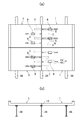
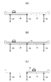
片車線開放下で施工する場合、図16(a)〜(c)に示すように、幅員方向中央で既設RC床版39を2分割し、片側のRC床版39を撤去した後、その部分に新たなプレキャスト床版14を架設し、また、図17(a)〜(c)に示すように、残りの他方の既設RC床版39を撤去した後、新たなプレキャスト床版15を架設する施工する手順で対向する各プレキャスト床版14,15を桁38上に載置するため、幅員中央部に上部長手方向の縦目地16ができ、幅員方向の横方向に縦目地間隙を介して隣り合うプレキャスト床版14,15を連結する必要がある。
When construction is performed with one lane open, as shown in FIGS. 16A to 16C, the existing
このために、従来は、短いPC鋼棒18を使用して、プレキャスト床版14,15相互を連結していた。
前記のように短いPC鋼棒18を使用する場合は、その緊張管理は難しく高度の熟練を必要とし、また、図19に示すように、前記PC鋼棒18の両端部が位置する部分にも、プレキャスト床版14,15には、切り欠き凹部46が必要となり、プレキャスト床版14,15に多数の切り欠き凹部46が必要となるため、プレキャスト床版14,15の疲労耐久性をより向上させることが望まれる。
When the short
本発明は、前記の短いPC鋼棒による難しい緊張管理の問題点とプレキャスト床版の疲労耐久性をより向上させることができるプレキャスト床版の連結構造を提供することを目的とする。 An object of the present invention is to provide a connection structure of a precast slab that can further improve the problem of difficult tension management by the short PC steel bar and the fatigue durability of the precast slab.
第1発明のプレキャスト床版の連結構造では、横方向に間隔を置いて並列配置されている桁38に渡って架設されるプレキャスト床版1,3相互の連結構造において、両方のプレキャスト床版1,3にプレストレス導入装置8を配置するための横孔2,4が設けられ、前記横孔2,4は連結側面に開孔する横孔とされ、前記連結側面で対向する一方の横孔は長尺の横孔4とされ、他方の横孔は短尺の横孔2とされ、前記の対向する長尺の横孔4と短尺の横孔2のうち、長尺の横孔4にのみその長手方向中間部において、前記長尺の横孔4に連通すると共に前記長尺の横孔4の下端レベルよりも深くかつ床版上面に開孔する切り欠き凹部5を備えたプレキャスト床版3(1)とされ、前記プレストレス導入装置8は中空PC鋼棒6の内部に押込み用反力PC鋼棒7を押込むことで緊張された前記中空PC鋼棒6を備えていると共に、一端部に後退するように回転させることにより押し込み用反力PC鋼棒7の圧縮力を開放するためのストッパ26を備えており、前記ストッパ26が前記切り欠き凹部5に位置するように前記各プレキャスト床版1,3の各横孔2,4内に渡って、長尺の横孔4から短尺の横孔2に引き出されたプレストレス導入装置8が配置されると共にプレストレス導入装置8を埋め込むように充填材が充填硬化され、かつ前記押込み用反力PC鋼棒7の圧縮力が解放されて前記中空PC鋼棒6により圧縮力が導入されて、横方向に隣り合うプレキャスト床版1,3が接近する方向にプレストレスが導入された状態で連結されていることを特徴とする。
In the connection structure of the precast floor slabs of the first invention, in the connection structure between the
また第2発明のプレキャスト床版の連結構造では、横方向に間隔を置いて並列配置されている桁38に渡って架設されるプレキャスト床版相互の連結構造において、両方のプレキャスト床版1,3にプレストレス導入装置8を配置するための凹部11,13が設けられ、前記凹部11,13は連結側面に開孔する凹部であると共に前記凹部11,13は、上部側の床版鉄筋が前記凹部11,13の部分で部分的に露出されている上向き開孔の凹部11,13とされ、前記の連結側面で対向する一方の凹部は長尺の凹部13とされ、他方の凹部は短尺の凹部11とされ、前記の対向する長尺の凹部13と短尺の凹部11のうち長尺の凹部13にのみその長手方向中間部において、前記長尺の凹部13に連通すると共に前記長尺の凹部13の下端レベルよりも深くかつ床版上面に開孔する切り欠き凹部5を備えたプレキャスト床版3(1)とされ、前記プレストレス導入装置8は中空PC鋼棒6の内部に押込み用反力PC鋼棒7を押込むことで緊張された前記中空PC鋼棒6を備えていると共に、一端部に後退するように回転させることにより押し込み用反力PC鋼棒7の圧縮力を開放するためのストッパ26を備えており、前記ストッパ26が前記切り欠き凹部5に位置するように前記各プレキャスト床版1,3の各凹部11,13内に渡って、長尺の凹部13から短尺の凹部11に引き出されたプレストレス導入装置8が配置されると共にプレストレス導入装置8を埋め込むように充填材が充填硬化され、かつ前記押込み用反力PC鋼棒7の圧縮力が解放されて前記中空PC鋼棒6により圧縮力が導入されて、横方向に隣り合うプレキャスト床版1,3が接近する方向にプレストレスが導入された状態で連結されていることを特徴とする。
In the connection structure of the precast floor slabs of the second invention, in the connection structure between the precast floor slabs installed over the
第3発明では、第1発明のプレキャスト床版の連結構造において、幅員方向の横方向に対向する一方または両方のプレキャスト床版1(3)に、前記プレストレス導入装置8の全長を収納可能な長尺の横孔4が設けられ、かつ前記長尺の横孔4に対向するプレキャスト床版1には、短尺の横孔2が設けられていることを特徴とする。
In the third invention, in the precast floor slab connection structure according to the first invention, the entire length of the
第4発明では、第3発明のプレキャスト床版の連結構造において、幅員方向に対向する一方または両方のプレキャスト床版1(3)に、前記プレストレス導入装置8の全長を収納可能な長尺の凹部13が設けられ、かつ前記長尺の凹部13に対向するプレキャスト床版1には、短尺の凹部11が設けられていることを特徴とする。
In 4th invention, in the connection structure of the precast floor slab of 3rd invention, the long length which can accommodate the full length of the said
第1発明または第2発明によると、中空PC鋼棒を備えたプレストレス導入装置を使用するので、予め工場において精度よく緊張管理されたプレストレス導入装置を使用することができるため、施工現場においては、押込み用PC鋼棒を開放する作業だけですむので、現場における緊張管理がほとんど不要である。 According to the first invention or the second invention, since the prestress introduction device provided with the hollow PC steel rod is used, it is possible to use the prestress introduction device which has been tension-controlled accurately in advance in the factory. Since it is only necessary to open the PC steel bar for pushing, tension management at the site is almost unnecessary.
従来のように短いPC鋼棒を使用しないので、短いPC鋼棒両端部を支承するための縦壁を有する切り欠き凹部を各プレキャスト床版に設ける必要がない。 Since a short PC steel bar is not used as in the prior art, it is not necessary to provide a notch recess having a vertical wall for supporting both ends of a short PC steel bar in each precast floor slab.
単にプレキャスト床版にプレストレス導入装置2を配置するための孔または凹部3を設けるだけで、容易にプレキャスト床版相互を接近する方向に所定のプレストレス力を与えて強固に連結することができるため、疲労耐久性をより確実に向上させることができる。
By simply providing a hole or
また、第1発明によると、少なくとも片側のプレキャスト床版の上面に凹部を設けないでよいので、片側のプレキャスト床版の上面のほぼ全面幅を有効に活用することができ、上面全面を交通の用に利用することができる。 Further, according to the first invention, since it is not necessary to provide a recess on the upper surface of at least one of the precast slabs, it is possible to effectively utilize the almost entire width of the upper surface of the one side of the precast slab. Can be used for.
長尺の横孔を有するプレキャスト床版を使用する場合は、この床版の長尺の横孔の中間部にのみ、切り欠き凹部を設ければよいので、従来の場合に比べて、切り欠き凹部の数を半減させることができる。 When using precast slab having a transverse bore of the elongated, only the intermediate portion of the transverse bore of the elongate this deck, since it is provided a cutout recess, as compared with the conventional case, notches The number of recesses can be halved.
第3発明または第4発明によると、幅員方向に対向する一方または両方のプレキャスト床版の長尺の横孔または凹部内に予め緊張された中空PC鋼棒を備えたプレストレス導入装置を配置することができるため、プレストレス導入装置の配置作業が簡単・容易になる。また、両方のプレキャスト床版に長尺の横孔または凹部が設けられていると、プレストレス導入装置を収容する横孔または凹部を橋軸方向に左右の床版に交互に設けることができるため、一方の床版に長尺の横孔または凹部が間隔をおいて連続してかたよることなく、対向するプレキャスト床版に均等に配置することができる。 According to the third or fourth aspect of the invention, the prestress introducing device including the pre-tensioned hollow PC steel bar is disposed in the long lateral hole or the concave portion of one or both precast slabs facing in the width direction. This makes it easy and easy to arrange the prestress introduction device. In addition, if both precast floor slabs are provided with long horizontal holes or recesses, the horizontal holes or recesses that accommodate the prestress introduction device can be alternately provided in the left and right floor slabs in the bridge axis direction. The long horizontal holes or the concave portions are not continuously arranged on one floor slab at intervals, and can be evenly arranged on the facing precast slab.
また、長尺の横孔の中間部に切り欠き凹部を設けるだけであるので、従来の場合よりも切り欠き凹部を少なくすることができ、また、解放治具をセットするための切り欠き凹部を両方のプレキャスト床版に設ける場合でも、一方のプレキャスト床版にかたよることなく、均等に配置することができる。また、短尺の横孔または凹部の奥部までプレストレス導入装置の先端部を配置することができるため、短尺の横孔または凹部側のプレキャスト床版を確実に補強することができる。 Moreover, since only a notch recess is provided in the middle part of the long horizontal hole, the notch recess can be reduced as compared with the conventional case, and a notch recess for setting the release jig is provided. Even when it is provided on both of the precast slabs, it can be arranged uniformly without depending on one of the precast slabs. Moreover, since the front-end | tip part of a prestress introduction apparatus can be arrange | positioned to the back part of a short horizontal hole or a recessed part, the precast floor slab by the side of a short horizontal hole or a recessed part can be reinforced reliably.
第5発明によると、中空PC鋼棒の配置が容易であると共に、無収縮モルタル等の充填を確認しながら確実に充填することができ、しかもプレキャスト床版とグラウトとの一体化を上部側の床版鉄筋を有効に利用して確実に一体化することができる。
According to the fifth aspect of the present invention, the hollow PC steel rod can be easily arranged, and can be reliably filled while confirming the filling of the non-shrink mortar, etc., and the integration of the precast floor slab and the grout can be performed on the upper side. The floor slab reinforcement can be used effectively and integrated reliably.
次に本発明を図示の実施形態に基づいて詳細に説明する。 Next, the present invention will be described in detail based on the illustrated embodiment.
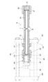
先ず、本発明において使用する反力PC鋼材によるプレストレス導入装置8の一形態の構造について、図9および図18を参照して説明する。
First, the structure of one form of the
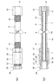
図9(a)は、本発明において使用する一実施形態の中空PC鋼棒を使用したコンクリート用プレストレス導入装置8の1ユニットの一部切欠側面図を示し、(b)はその縦断側面図を示すものであって、鋼製中空PC鋼棒本体6aの長手方向の一端部(前端部)外側に雄ねじ部20を有すると共に、他端部(後端部)外側に雄ねじ部21を有する中空PC鋼棒6における前記雄ねじ部21に、前後両端部に雌ねじ孔22、23を有すると共に多角形の回動工具係合用外面24を有する支承筒25における前端部の雌ねじ孔22が螺合連結されている。
Fig.9 (a) shows the partially cutaway side view of 1 unit of the
前記支承筒25の後端部の雌ねじ孔23に、鋼製筒状の環状係止片からなるストッパ26の前部雄ねじ部27が螺合され、前記ストッパ26の後端部外側には、回動工具係合用外面28が形成されている。
A front
前記ストッパ26の前端部は、前記支承筒25の内部に配置され、前端部に凹部29を有する押圧係止片30の後端面が係合され、前記押圧係止片30の前端部の凹部29には、中空PC鋼棒6内に他端側を除くほぼ全体が挿入され、かつ他端側が前記中空PC鋼棒6の他端部から突出するように配置された押込み用反力PC鋼棒(ノンプル用反力PC鋼棒)7の後端部が嵌合されている。
The front end portion of the
なお、前記のノンプルとは、引き抜かない方式で、換言すると据え置き方式の意味である。 Note that the non-pull means a system that does not pull out, in other words, a stationary system.
この実施形態においては、1本ものの押込み用反力PC鋼棒7により押込み鋼棒を構成しているが、他端側に短尺の撤去用反力PC鋼棒と前記押込み用反力PC鋼棒7よりも若干短尺な押込み用反力PC鋼棒との2本により押し込み用反力PC鋼棒7を構成することも可能である。
In this embodiment, the
前記中空PC鋼棒6の前端部外側の雄ねじ20に、雌ねじ部31を有するナットからなるアンカー材32が着脱自在に螺合固定され、前記押込み用反力PC鋼棒7の先端部は前記雌ねじ部31に連結されている。前記アンカー材32には雄ねじ部材41が螺合固定され、前記雄ねじ部材41により反力PC鋼棒7の先端部が支承されている。
An
図9に示す状態は、図18に示すような状態にプレストレス導入装置8を、前部フレーム43および後部フレーム44を複数の連結ロッド45で平行に結合し、後部フレーム44側に油圧ジャッキ34を備えた枠形フレーム33に配置して、液圧ジャッキ34を利用して、その可動ピストン35の先端部に係合され、ストッパ26の中央中空部に挿入される押し込み鋼棒36により押圧係止片30を前記中空PC鋼棒6に向かって移動するように押圧し、前記押込み用反力PC鋼棒7を中空PC鋼棒6内に押し込むように圧縮力を導入した後、その状態においてフリーになっている前記支承筒25またはストッパ26を前記押圧係止片30に向かって接近する方向(図9の右方向)に回転させて、前記ストッパ26を前進移動して、ストッパ26の前端部を押し込み係止片30に係合させ、枠形フレーム33から分離させた状態を示した図である。
In the state shown in FIG. 9, the
このようなプレストレス導入装置8は、特開2001−207590号公報等により公知であり、押込み用反力PC鋼棒および中空PC鋼棒を備えた各種の形態の装置を使用することもできる。
Such a
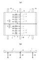
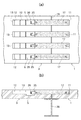
次に、本発明において使用されるプレキャスト床版の第1実施形態の構造形態について、図1および図2を参照して説明する。 Next, the structure form of 1st Embodiment of the precast slab used in this invention is demonstrated with reference to FIG. 1 and FIG.
幅員方向中央の桁38の中央部から幅員方向片側の既設RC床版39が撤去された後に、先行して片側の複数の桁38に渡って架設されるプレキャスト床版1として、前記プレストレス導入装置8の長さよりも短い(図示形態では、プレストレス導入装置8の長さのほぼ半分の長さ)、プレストレス導入装置8の一部を収納可能な短尺の横孔2を厚さ方向の上部側に備えたプレキャスト床版1が使用されている。なお、図示のプレキャスト床版1は、図示省略の埋め込み固定されたPC鋼材によりプレストレスが付与されたプレキャストのPC床版である。
After the existing
前記短尺の横孔2は、プレキャスト床版1における幅員方向(道路巾方向等)の中央側となる内端面に開孔する横孔とされ、かつ、橋軸方向に間隔をおいて複数備えており、各横孔2における奥部側には、床版上面に開孔するグラウト孔2aを備えている。
The short
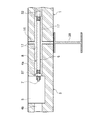
幅員方向他方の既設RC床版39が撤去された後に、後行して架設されるプレキャスト床版2として、前記プレストレス導入装置8の長さと同程度かこれよりも長い、プレストレス導入装置のほぼ全長を収納可能で、接合端面側となる中央側となる内端面に開孔する長尺の横孔4を厚さ方向の上部側に備えたプレキャスト床版3が使用されている。
As the
後行する前記プレキャスト床版3には、前記横孔4の長手方向中間部において、前記横孔4に連通すると共に前記横孔4の下端レベルよりも若干深く、かつ床版上面に開孔する切り欠き凹部5を備えている。
The following
したがって、前記の長尺の横孔4は、前記の切り欠き凹部5と、その切り欠き凹部5における幅員方向両側の横孔4a,4bとにより構成されている。
Therefore, the long
また、前記長尺の横孔4の奥部側の横孔4bには、床版上面に開孔するグラウト孔4cが設けられ、また、幅員中央部側の前記切り欠き凹部5に近傍した位置に、幅員中央部側の横孔4aに連通すると共に床版上面に開孔するグラウト孔4cが設けられている。
Further, the
前記長尺の横孔4および切り欠き凹部5を橋軸方向に間隔をおいて平行に設けている。
The long
前記のような長尺の横孔4を有するプレキャスト床版3における前記各長尺の横孔4内に、プレストレス導入装置8が、幅員中央部側の内端面側から、挿入されると共に、プレストレス導入装置8におけるストッパ26側が横孔4(4b)の奥部に位置するように、プレキャスト床版3の架設直前等に予め収納配置され、必要に応じ切り欠き凹部5に仮保持治具を配置して適宜仮保持された状態で、先行して架設されたプレキャスト床版1に縦目地16の間隙を介して桁38に架設されている。
A
なお、複数の桁38間に渡って架設される前記の先行または後行のプレキャスト床版1,3は、各桁38上に適宜調整用モルタルが設けられて架設されている。
The preceding or succeeding
なお、前記の目地間隙部の中央部の桁38上には、適宜スタッドジベル等のジベルが設けられるが図示を省略した。
A gibber such as a stud gibber is appropriately provided on the
次に、前記のプレストレス導入装置8を使用した、本発明のプレキャスト床版の連結構造について、図1〜図7に示す施工手順および図8に示す完成した本発明の第1実施形態のプレキャスト床版の連結構造を順次参照して説明する。
Next, the precast floor slab connection structure of the present invention using the
図1および図2は、図16および図17に示すように、既設のRC床版39が撤去されて、先行および後行に架設される新設のプレキャスト床版1,3が架設された状態である。
FIGS. 1 and 2 show a state in which the existing
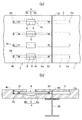
図1および図2の状態から、図3(a),(b)に示すように、プレキャスト床版3における切り欠き凹部5内に位置する部分のプレストレス導入装置8を作業員により把持して対向する他方のプレキャスト床版1の横孔内に引き出し配置する。なお、図3〜図6に示すように、切り欠き凹部5にプレストレス導入装置8の一端部のストッパ26を位置させる。
From the state of FIG. 1 and FIG. 2, as shown in FIGS. 3 (a) and 3 (b), the operator holds the
次いで、図4および図5に示すように、プレキャスト床版1,3間の縦目地部に、対向するプレキャスト床版1,3相互の短尺および長尺の横孔2,4が連通するように分割型筒状型枠(図示省略)を配置した状態で、無収縮モルタル等のグラウトからなる充填剤を充填する。
Next, as shown in FIG. 4 and FIG. 5, the short and long
また、先行するプレキャスト床版1における短尺の横孔2、または後行するプレキャスト床版4における中央部側のグラウト孔4cから、無収縮モルタル等のグラウト17からなる充填剤を、短尺の横孔2から切り欠き凹部5の幅員中央部側の端面まで注入充填し、プレストレス導入装置8の先端部からプレストレス導入装置8における雄ねじ部21に螺合されたアンカー材37まで埋め込む。なお、適宜切り欠き凹部5側には型枠(図示を省略した)を配置する。
Further, from the short
前記グラウト17からなる充填剤が硬化し所定の強度を発揮した後(プレストレス導入装置8との付着が充分となった後)、図6に示すように、切り欠き凹部5側のプレストレス導入装置8の一端部のストッパ26に、これに嵌合可能な多角形内側係合部を有する筒状歯車からなる出力軸10を備えた歯車機構を有する解放治具9をセットする。
After the filler made of the
また、前記解放治具9における多角形内側係合部を有する筒状歯車からなる入力軸10aに、電動式または手動式の回動工具における出力軸を嵌合して、前記ストッパ26を後退するように回転させることにより、押込み用反力PC鋼棒7の圧縮力が開放され、反対に、中空PC鋼棒6とグラウト17との付着およびグラウト17と各プレキャスト床版1,3の付着によって、中空PC鋼棒6の短縮が阻まれ、これにより相対的に各プレキャスト床版1,3が接近する方向に圧縮のプレストレスが導入され、強固に接合され一体化される。
Further, the
中空PC鋼棒6とグラウト17からなる充填剤との付着が十分であれば、アンカー材32とアンカー部材37は、原理的には省略することもできる。
If the adhesion between the hollow
なお、前記のストッパ26および支承筒25は取り外し、押込み用反力PC鋼棒7は取り外すことも可能であるが、図7に示すように、押込み用反力PC鋼棒7を残置させるノンプル用の反力PC鋼棒7とすることも可能である。
The
押込み用反力PC鋼棒7を残置させる場合、前記支承筒25を中空PC鋼棒6から取り外し、グラウト17からなる充填剤の硬化した後に硬化し、中空PC鋼棒6と押込み用反力PC鋼棒7の一体性を高め、接合されたプレキャスト床版1,3の終局耐力を向上させるため、適宜遅延剤を硬化型接着剤に混合させてなる経時硬化型の合成樹脂製接着剤からなる接着兼用防錆材40が中空PC鋼棒6の端部開口部から予めあるいは適宜の時期に注入充填される。
When the pushing reaction force
その後、前記支承筒25を取り外した後、押込み用反力PC鋼棒7を回収することなく、前記中空PC鋼棒6内に据え置き、防錆を兼ねる経時硬化製樹脂等の接着兼用防錆材40の硬化により中空PC鋼棒6と押込み用PC鋼棒7の一体化を図る。
Then, after removing the
その後、図8に示すように、グラウト17を充填していない長尺の横孔4の奥部側の横孔4bに、グラウト孔4cからグラウト17を充填すると共に、切り欠き凹部5内に無収縮モルタル等のグラウト17を充填して、中空PC鋼棒6および反力PC鋼棒7の防錆を図り、プレキャスト床版1,3相互の連結を完了する。
Thereafter, as shown in FIG. 8, the
この第1実施形態では、プレキャスト床版1の上面に凹部がないので、床版巾方向全幅を有効に交通等の用に利用することができる。
In this 1st Embodiment, since there is no recessed part in the upper surface of the
(第1実施形態の変形形態)
図10(a),(b)は、先行するプレキャスト床版1および後行するプレキャスト床版3として、中間部に切り欠き凹部5を有する長尺の横孔4と、短尺の横孔2とを橋軸長手方向に間隔をおいて平行に交互に設けたプレキャスト床版1,3を使用し、かつ幅員方向に対向する各プレストレストコンクリート床版1,3の長尺の横孔4と短尺の横孔2とを対向するように配置し、切り欠き凹部5を橋軸方向に千鳥状に配置するようにした形態である。
(Modification of the first embodiment)
10 (a) and 10 (b) illustrate a
このように、切り欠き凹部5を交互に千鳥状に配置すると、切り欠き凹部5による断面欠損が一方のプレストレストコンクリート床版に集中することがなく、また短い間隔で橋軸方向に直線状に設けないですむので、長尺の横孔4と短尺の横孔2とを比較的密に配置することができる。
When the notch recesses 5 are alternately arranged in a staggered manner in this way, the cross-sectional defects due to the notch recesses 5 are not concentrated on one prestressed concrete floor slab, and are provided in a straight line in the bridge axis direction at short intervals. Therefore, the long
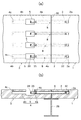
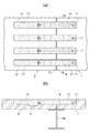
(第2実施形態)
図11〜図14は、本発明における第2実施形態のプレキャスト床版の連結構造を施工途中の状態を示し、図15は、連結を完了した状態を示している。
(Second Embodiment)
FIGS. 11-14 shows the state in the middle of construction of the connection structure of the precast floor slab of 2nd Embodiment in this invention, FIG. 15 has shown the state which completed the connection.
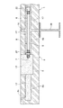
幅員方向中央の桁38の中央部から幅員方向片側の既設RC床版39が撤去された後に、先行して片側の複数の桁38に渡って架設されるプレキャスト床版1として、この第2実施形態で使用されているプレストレストコンクリート床版1は、前記プレストレス導入装置8の長さよりも短くプレストレス導入装置8の一部を収納可能な、上部および幅員方向(道路巾方向等)の中央側となる内端面(接合端面)に開口し、厚さ方向の上部側に設けられた幅員方向寸法が短尺の凹部11(ほぼプレストレス導入装置8の半分の長さ)で、かつ前記凹部11内に位置する上部側の間隔をおく床版鉄筋12を露出させた状態の凹部11とされたプレストレストコンクリート床版1が使用されている。
As the
前記短尺の凹部11を橋軸方向に間隔をおいて平行に複数備えており、床版上面側からのグラウト17が容易にされ、また、プレストレス導入装置8を番線等により床版鉄筋12に保持させることにより、プレストレス導入装置8の配置を傾斜することなく確実に中心位置に保持可能にされている。
A plurality of the
次いで、幅員方向中央の桁38の中央部から幅員方向他方の既設RC床版39が撤去された後に、後行して架設されるプレキャスト床版3として、前記プレストレス導入装置8の長さと同程度かこれよりも若干長く、上部および幅員方向(道路巾方向等)の中央側となる内端面(接合端面)に開口し、プレストレス導入装置8のほぼ全長を収納可能で、かつ前記凹部11内に位置する上部側の間隔をおく床版鉄筋12を露出させた状態の長尺の上向き開孔凹部13を厚さ方向の上部側に設けたプレキャスト床版3が使用されている。
Subsequently, after the existing
前記長尺の凹部13を橋軸方向に間隔をおいて平行に備えており、床版上面側からのグラウト17が容易なプレキャスト床版3とされ、また、プレストレス導入装置8を番線等により床版鉄筋12に保持させることにより、仮保持させたり、プレストレス導入装置8の配置を傾斜することなく確実に中心位置に保持可能にされている。
The long
図11には、前記のような長尺の凹部13を有するプレキャスト床版3における前記各長尺の凹部13内に、プレストレス導入装置8が、幅員中央部側の内端面側の凹部13の開口部から挿入されると共に、プレストレス導入装置8におけるストッパ26側が凹部13の奥部に位置するように、工場または現場付近のヤードにおいて、プレキャスト床版3の架設直前等に予め収納配置された状態で、先行するプレキャスト床版1に目地間隙を介して複数の桁38に架設されている状態が示されている。
In FIG. 11, the
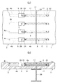
この状態から図12(a),(b)に示すように、プレキャスト床版3における長尺の凹部13内のプレストレス導入装置8を作業員により把持して対向する他方のプレキャスト床版1の凹部11内奥部まで引き出し配置し、適宜番線等により各凹部11,13の中心軸線上に位置するように保持する。
From this state, as shown in FIGS. 12A and 12B, the
次いで、図13(a),(b)に示すように、プレキャスト床版1,3間の縦目地部、および対向するプレキャスト床版1,3相互の短尺および長尺の凹部11,13内に配置されたプレストレス導入装置8の先端部からアンカー材37までを埋め込むように、無収縮モルタル等のグラウト17を充填する。なお、アンカー材37の外側には、適宜型枠(図示省略)を配置しておく。
Next, as shown in FIGS. 13 (a) and 13 (b), in the vertical joint between the
前記グラウト17が硬化し所定の強度を発揮した後(プレストレス導入装置8との付着が充分となった後)、図14(a),(b)に示すように、長尺の凹部13側のプレストレス導入装置8の一端部のストッパ26に、前記実施形態と同様、解放治具9をセットする。床版鉄筋間において、開放治具9をセット可能なように、プレストレス導入装置8におけるストッパ26を床版鉄筋12から突出した位置になるように、プレストレス導入装置8を配置しておくと望ましい。
After the
そして、前記実施形態と同様に、前記ストッパ26を後退するように回転させることにより、押込み用反力PC鋼棒7の圧縮力が開放され、反対に、中空PC鋼棒6とグラウト17との付着およびグラウト17と各プレキャスト床版1,3の付着によって、中空PC鋼棒6の短縮が阻まれ、これにより相対的に各プレキャスト床版1,3が接近する方向に圧縮のプレストレスが導入され、強固に接合され一体化される。
Then, as in the above embodiment, the compression force of the pushing reaction force
前記のストッパ26および支承筒25は取り外し、プレストレス導入装置8を埋めこむように残りの凹部13内に、図15に示すように無収縮モルタル等のグラウト17を充填・硬化させて、プレキャスト床版相互を強固に連結する。
The
図示の実施形態では、横方向に間隔をおく3つの桁38のうち、2つの桁38間にプレキャスト床版1,3を架設するようにした形態が示されているが、本発明を実施する場合、3つ以上の桁38に渡ってプレキャスト床版1(3)を架設するようにしてもよい。
In the illustrated embodiment, a form in which the
1 先行して架設されるプレキャスト床版
2 短尺の横孔
3 後行して架設されるプレキャスト床版
4 長尺の横孔
4a 横孔
4b 横孔
5 切り欠き凹部
6 中空PC鋼棒
6a 中空PC鋼棒本体
7 押込み用反力PC鋼棒
8 プレストレス導入装置
9 解放治具
10 出力軸
11 凹部
12 床版鉄筋
13 長尺の凹部
14 新たなプレキャスト床版
15 新たなプレキャスト床版
16 縦目地
17 グラウト
18 短いPC鋼棒
20 雄ねじ部
21 雄ねじ部
22 雌ねじ孔
23 雌ねじ孔
24 回動工具係合用外面
25 支承筒
26 ストッパ
27 前部雄ねじ部
28 回動工具係合用外面
29 凹部
30 押圧係止片
31 雌ねじ部
32 アンカー材
33 枠形フレーム
34 液圧ジャッキ
35 可動ピストン
36 押込み鋼棒
37 アンカー材
38 桁
39 既設RC床版
40 接着兼用防錆材
41 雄ねじ部材
43 前部フレーム
44 後部フレーム
45 連結ロッド
46 切り欠き凹部
DESCRIPTION OF
Claims (4)
Priority Applications (1)
| Application Number | Priority Date | Filing Date | Title |
|---|---|---|---|
| JP2003326369A JP4148317B2 (en) | 2003-09-18 | 2003-09-18 | Connecting structure of precast slab |
Applications Claiming Priority (1)
| Application Number | Priority Date | Filing Date | Title |
|---|---|---|---|
| JP2003326369A JP4148317B2 (en) | 2003-09-18 | 2003-09-18 | Connecting structure of precast slab |
Publications (2)
| Publication Number | Publication Date |
|---|---|
| JP2005090124A JP2005090124A (en) | 2005-04-07 |
| JP4148317B2 true JP4148317B2 (en) | 2008-09-10 |
Family
ID=34456579
Family Applications (1)
| Application Number | Title | Priority Date | Filing Date |
|---|---|---|---|
| JP2003326369A Expired - Fee Related JP4148317B2 (en) | 2003-09-18 | 2003-09-18 | Connecting structure of precast slab |
Country Status (1)
| Country | Link |
|---|---|
| JP (1) | JP4148317B2 (en) |
Families Citing this family (9)
| Publication number | Priority date | Publication date | Assignee | Title |
|---|---|---|---|---|
| JP4953775B2 (en) * | 2006-11-09 | 2012-06-13 | オリエンタル白石株式会社 | Prestress introduction device and anchor structure thereof |
| JP5363930B2 (en) * | 2009-09-24 | 2013-12-11 | 大成建設株式会社 | Precast member joining structure and construction method thereof |
| CN103362062A (en) * | 2013-01-08 | 2013-10-23 | 韩志群 | Connector girder |
| JP6323776B2 (en) * | 2014-02-14 | 2018-05-16 | 株式会社高速道路総合技術研究所 | Replacement method of concrete floor slab for elevated road and replacement PC floor slab by the same method |
| KR101631526B1 (en) * | 2014-03-11 | 2016-06-17 | 고려개발 주식회사 | The seismic retrofit method of bridge columns using external tendons |
| JP6150138B2 (en) * | 2014-11-18 | 2017-06-21 | 株式会社ピーエス三菱 | Construction method of concrete floor slab for elevated road |
| JP6811678B2 (en) * | 2017-05-15 | 2021-01-13 | 東京製綱株式会社 | Method of joining concrete structures and concrete members to which continuous fiber reinforced concrete is applied |
| JP7260849B2 (en) * | 2019-05-15 | 2023-04-19 | 株式会社大林組 | Precast concrete member and its connection structure |
| JP7561635B2 (en) * | 2021-01-14 | 2024-10-04 | 株式会社安藤・間 | Concrete member, concrete member joint structure, and concrete member joining method |
-
2003
- 2003-09-18 JP JP2003326369A patent/JP4148317B2/en not_active Expired - Fee Related
Also Published As
| Publication number | Publication date |
|---|---|
| JP2005090124A (en) | 2005-04-07 |
Similar Documents
| Publication | Publication Date | Title |
|---|---|---|
| JP5258099B2 (en) | Prestressed concrete pile, method for manufacturing the same, and method for connecting pile head and footing | |
| JP2018076733A (en) | Method for constructing connection structure of precast structural member and time-hardening material | |
| JP4148317B2 (en) | Connecting structure of precast slab | |
| JP2007239301A (en) | Method of integrating precast concrete members interposed by filling concrete | |
| JP2003328561A (en) | Method for reinforcing concrete member and tensioning device for tension member used for the method | |
| KR101293838B1 (en) | Apparatus for manufacturing pretensioned concrete and method for manufacturing prestressed structure using the same | |
| JP7217673B2 (en) | Concrete floor slab, method for forming concrete floor slab, and method for repairing concrete floor slab | |
| KR100609184B1 (en) | Precast Concrete Beam-Column Connection Structure | |
| JP4413765B2 (en) | Pre-tension hollow girder horizontal fastening PC steel temporary fixing device and fixing method | |
| JP2528432B2 (en) | Reinforcement method for concrete structure using hollow PC steel rod | |
| JP2005325518A (en) | Prestress introduction unit and prestress introduction method | |
| JP3810759B2 (en) | Edge widening structure of existing substructure by precast block and its construction method | |
| JP2003285316A (en) | Precast pc member, manufacturing method therefor and joining method for precast pc member and another member | |
| JP4953775B2 (en) | Prestress introduction device and anchor structure thereof | |
| JP3495720B2 (en) | PC structure in which concrete members with different construction periods are integrated and its construction method | |
| JP2007063796A (en) | Structure and method for widening connection of bridge | |
| JP3989474B2 (en) | Prestress force introduction device anchoring structure and prestressed joint structure | |
| JP7144341B2 (en) | Concrete floor slab joint structure and concrete floor slab joint method | |
| JP7186670B2 (en) | Concrete floor slab repair method | |
| JP2006161446A (en) | Web unit for bridge and manufacturing method of main girder making use of the web unit | |
| JP2005097995A (en) | Precast prestressed concrete member and joining method for precast prestressed concrete member and the other member | |
| JP2005155282A (en) | Extruding construction method for prestressed concrete bridge | |
| JP7034229B2 (en) | How to build a connected structure of precast structural member and cast-in-place cured material of repaired part of cross-section repair | |
| US3790657A (en) | Method of and device for the formation of beam structures | |
| JPH09221915A (en) | Prestress introducing unit |
Legal Events
| Date | Code | Title | Description |
|---|---|---|---|
| A621 | Written request for application examination |
Free format text: JAPANESE INTERMEDIATE CODE: A621 Effective date: 20060420 |
|
| A977 | Report on retrieval |
Free format text: JAPANESE INTERMEDIATE CODE: A971007 Effective date: 20080313 |
|
| A131 | Notification of reasons for refusal |
Free format text: JAPANESE INTERMEDIATE CODE: A131 Effective date: 20080401 |
|
| A521 | Written amendment |
Free format text: JAPANESE INTERMEDIATE CODE: A523 Effective date: 20080523 |
|
| TRDD | Decision of grant or rejection written | ||
| A01 | Written decision to grant a patent or to grant a registration (utility model) |
Free format text: JAPANESE INTERMEDIATE CODE: A01 Effective date: 20080617 |
|
| A01 | Written decision to grant a patent or to grant a registration (utility model) |
Free format text: JAPANESE INTERMEDIATE CODE: A01 |
|
| A61 | First payment of annual fees (during grant procedure) |
Free format text: JAPANESE INTERMEDIATE CODE: A61 Effective date: 20080617 |
|
| FPAY | Renewal fee payment (event date is renewal date of database) |
Free format text: PAYMENT UNTIL: 20110704 Year of fee payment: 3 |
|
| R150 | Certificate of patent or registration of utility model |
Free format text: JAPANESE INTERMEDIATE CODE: R150 Ref document number: 4148317 Country of ref document: JP Free format text: JAPANESE INTERMEDIATE CODE: R150 |
|
| FPAY | Renewal fee payment (event date is renewal date of database) |
Free format text: PAYMENT UNTIL: 20110704 Year of fee payment: 3 |
|
| S531 | Written request for registration of change of domicile |
Free format text: JAPANESE INTERMEDIATE CODE: R313531 |
|
| FPAY | Renewal fee payment (event date is renewal date of database) |
Free format text: PAYMENT UNTIL: 20110704 Year of fee payment: 3 |
|
| R350 | Written notification of registration of transfer |
Free format text: JAPANESE INTERMEDIATE CODE: R350 |
|
| FPAY | Renewal fee payment (event date is renewal date of database) |
Free format text: PAYMENT UNTIL: 20120704 Year of fee payment: 4 |
|
| R250 | Receipt of annual fees |
Free format text: JAPANESE INTERMEDIATE CODE: R250 |
|
| FPAY | Renewal fee payment (event date is renewal date of database) |
Free format text: PAYMENT UNTIL: 20130704 Year of fee payment: 5 |
|
| R250 | Receipt of annual fees |
Free format text: JAPANESE INTERMEDIATE CODE: R250 |
|
| R250 | Receipt of annual fees |
Free format text: JAPANESE INTERMEDIATE CODE: R250 |
|
| R250 | Receipt of annual fees |
Free format text: JAPANESE INTERMEDIATE CODE: R250 |
|
| R250 | Receipt of annual fees |
Free format text: JAPANESE INTERMEDIATE CODE: R250 |
|
| R250 | Receipt of annual fees |
Free format text: JAPANESE INTERMEDIATE CODE: R250 |
|
| R250 | Receipt of annual fees |
Free format text: JAPANESE INTERMEDIATE CODE: R250 |
|
| R250 | Receipt of annual fees |
Free format text: JAPANESE INTERMEDIATE CODE: R250 |
|
| LAPS | Cancellation because of no payment of annual fees |