JP4146304B2 - Shaft-boss connection - Google Patents
Shaft-boss connection Download PDFInfo
- Publication number
- JP4146304B2 JP4146304B2 JP2003192776A JP2003192776A JP4146304B2 JP 4146304 B2 JP4146304 B2 JP 4146304B2 JP 2003192776 A JP2003192776 A JP 2003192776A JP 2003192776 A JP2003192776 A JP 2003192776A JP 4146304 B2 JP4146304 B2 JP 4146304B2
- Authority
- JP
- Japan
- Prior art keywords
- boss
- bush
- shaft
- connection
- flange
- Prior art date
- Legal status (The legal status is an assumption and is not a legal conclusion. Google has not performed a legal analysis and makes no representation as to the accuracy of the status listed.)
- Expired - Fee Related
Links
- 229910000906 Bronze Inorganic materials 0.000 claims abstract description 5
- 239000010974 bronze Substances 0.000 claims abstract description 5
- KUNSUQLRTQLHQQ-UHFFFAOYSA-N copper tin Chemical compound [Cu].[Sn] KUNSUQLRTQLHQQ-UHFFFAOYSA-N 0.000 claims abstract description 5
- 230000008878 coupling Effects 0.000 claims description 5
- 238000010168 coupling process Methods 0.000 claims description 5
- 238000005859 coupling reaction Methods 0.000 claims description 5
- 230000002093 peripheral effect Effects 0.000 claims 2
- 239000012791 sliding layer Substances 0.000 claims 1
- 238000007767 slide coating Methods 0.000 abstract 1
- 230000003628 erosive effect Effects 0.000 description 3
- 230000001419 dependent effect Effects 0.000 description 2
- 238000000034 method Methods 0.000 description 2
- 230000000694 effects Effects 0.000 description 1
- 230000035939 shock Effects 0.000 description 1
Images

Classifications
-
- F—MECHANICAL ENGINEERING; LIGHTING; HEATING; WEAPONS; BLASTING
- F16—ENGINEERING ELEMENTS AND UNITS; GENERAL MEASURES FOR PRODUCING AND MAINTAINING EFFECTIVE FUNCTIONING OF MACHINES OR INSTALLATIONS; THERMAL INSULATION IN GENERAL
- F16D—COUPLINGS FOR TRANSMITTING ROTATION; CLUTCHES; BRAKES
- F16D43/00—Automatic clutches
- F16D43/02—Automatic clutches actuated entirely mechanically
- F16D43/20—Automatic clutches actuated entirely mechanically controlled by torque, e.g. overload-release clutches, slip-clutches with means by which torque varies the clutching pressure
- F16D43/21—Automatic clutches actuated entirely mechanically controlled by torque, e.g. overload-release clutches, slip-clutches with means by which torque varies the clutching pressure with friction members
- F16D43/211—Automatic clutches actuated entirely mechanically controlled by torque, e.g. overload-release clutches, slip-clutches with means by which torque varies the clutching pressure with friction members with radially applied torque-limiting friction surfaces
-
- F—MECHANICAL ENGINEERING; LIGHTING; HEATING; WEAPONS; BLASTING
- F16—ENGINEERING ELEMENTS AND UNITS; GENERAL MEASURES FOR PRODUCING AND MAINTAINING EFFECTIVE FUNCTIONING OF MACHINES OR INSTALLATIONS; THERMAL INSULATION IN GENERAL
- F16D—COUPLINGS FOR TRANSMITTING ROTATION; CLUTCHES; BRAKES
- F16D1/00—Couplings for rigidly connecting two coaxial shafts or other movable machine elements
- F16D1/06—Couplings for rigidly connecting two coaxial shafts or other movable machine elements for attachment of a member on a shaft or on a shaft-end
- F16D1/08—Couplings for rigidly connecting two coaxial shafts or other movable machine elements for attachment of a member on a shaft or on a shaft-end with clamping hub; with hub and longitudinal key
- F16D1/09—Couplings for rigidly connecting two coaxial shafts or other movable machine elements for attachment of a member on a shaft or on a shaft-end with clamping hub; with hub and longitudinal key with radial clamping due to axial loading of at least one pair of conical surfaces
- F16D1/093—Couplings for rigidly connecting two coaxial shafts or other movable machine elements for attachment of a member on a shaft or on a shaft-end with clamping hub; with hub and longitudinal key with radial clamping due to axial loading of at least one pair of conical surfaces using one or more elastic segmented conical rings forming at least one of the conical surfaces, the rings being expanded or contracted to effect clamping
- F16D1/095—Couplings for rigidly connecting two coaxial shafts or other movable machine elements for attachment of a member on a shaft or on a shaft-end with clamping hub; with hub and longitudinal key with radial clamping due to axial loading of at least one pair of conical surfaces using one or more elastic segmented conical rings forming at least one of the conical surfaces, the rings being expanded or contracted to effect clamping with clamping effected by ring contraction only
-
- F—MECHANICAL ENGINEERING; LIGHTING; HEATING; WEAPONS; BLASTING
- F16—ENGINEERING ELEMENTS AND UNITS; GENERAL MEASURES FOR PRODUCING AND MAINTAINING EFFECTIVE FUNCTIONING OF MACHINES OR INSTALLATIONS; THERMAL INSULATION IN GENERAL
- F16D—COUPLINGS FOR TRANSMITTING ROTATION; CLUTCHES; BRAKES
- F16D7/00—Slip couplings, e.g. slipping on overload, for absorbing shock
- F16D7/02—Slip couplings, e.g. slipping on overload, for absorbing shock of the friction type
- F16D7/021—Slip couplings, e.g. slipping on overload, for absorbing shock of the friction type with radially applied torque-limiting friction surfaces
-
- F—MECHANICAL ENGINEERING; LIGHTING; HEATING; WEAPONS; BLASTING
- F16—ENGINEERING ELEMENTS AND UNITS; GENERAL MEASURES FOR PRODUCING AND MAINTAINING EFFECTIVE FUNCTIONING OF MACHINES OR INSTALLATIONS; THERMAL INSULATION IN GENERAL
- F16B—DEVICES FOR FASTENING OR SECURING CONSTRUCTIONAL ELEMENTS OR MACHINE PARTS TOGETHER, e.g. NAILS, BOLTS, CIRCLIPS, CLAMPS, CLIPS OR WEDGES; JOINTS OR JOINTING
- F16B2200/00—Constructional details of connections not covered for in other groups of this subclass
- F16B2200/50—Flanged connections
- F16B2200/506—Flanged connections bolted or riveted
-
- Y—GENERAL TAGGING OF NEW TECHNOLOGICAL DEVELOPMENTS; GENERAL TAGGING OF CROSS-SECTIONAL TECHNOLOGIES SPANNING OVER SEVERAL SECTIONS OF THE IPC; TECHNICAL SUBJECTS COVERED BY FORMER USPC CROSS-REFERENCE ART COLLECTIONS [XRACs] AND DIGESTS
- Y10—TECHNICAL SUBJECTS COVERED BY FORMER USPC
- Y10T—TECHNICAL SUBJECTS COVERED BY FORMER US CLASSIFICATION
- Y10T403/00—Joints and connections
- Y10T403/10—Selectively engageable hub to shaft connection
-
- Y—GENERAL TAGGING OF NEW TECHNOLOGICAL DEVELOPMENTS; GENERAL TAGGING OF CROSS-SECTIONAL TECHNOLOGIES SPANNING OVER SEVERAL SECTIONS OF THE IPC; TECHNICAL SUBJECTS COVERED BY FORMER USPC CROSS-REFERENCE ART COLLECTIONS [XRACs] AND DIGESTS
- Y10—TECHNICAL SUBJECTS COVERED BY FORMER USPC
- Y10T—TECHNICAL SUBJECTS COVERED BY FORMER US CLASSIFICATION
- Y10T403/00—Joints and connections
- Y10T403/70—Interfitted members
- Y10T403/7047—Radially interposed shim or bushing
- Y10T403/7051—Wedging or camming
- Y10T403/7052—Engaged by axial movement
- Y10T403/7054—Plural, circumferentially related shims between members
-
- Y—GENERAL TAGGING OF NEW TECHNOLOGICAL DEVELOPMENTS; GENERAL TAGGING OF CROSS-SECTIONAL TECHNOLOGIES SPANNING OVER SEVERAL SECTIONS OF THE IPC; TECHNICAL SUBJECTS COVERED BY FORMER USPC CROSS-REFERENCE ART COLLECTIONS [XRACs] AND DIGESTS
- Y10—TECHNICAL SUBJECTS COVERED BY FORMER USPC
- Y10T—TECHNICAL SUBJECTS COVERED BY FORMER US CLASSIFICATION
- Y10T403/00—Joints and connections
- Y10T403/70—Interfitted members
- Y10T403/7062—Clamped members
- Y10T403/7064—Clamped members by wedge or cam
- Y10T403/7066—Clamped members by wedge or cam having actuator
- Y10T403/7067—Threaded actuator
Abstract
Description
【0001】
【発明の属する技術分野】
本発明は、接続フランジと、この接続フランジに固定可能な締付け部材、特に締付けリングとを有し、その締付けリングによって、接続フランジに対応づけられている軸端部がスリップモーメントを吸収するブッシュを介在させて摩擦結合で接続フランジと結合可能である、軸−ボス結合に関する。
【0002】
【従来の技術】
実際から知られているこの種の軸−ボス結合は、短時間に発生する、特に高周波のトルク衝撃のための過負荷保護として用いられる。このようにして、結合された機械は、トルク衝撃によってもたらされる過負荷損傷から保護される。これは、締付け部材と軸端部との間に配置されているブッシュがスリップモーメントを吸収することができることによってもたらされ、そのスリップモーメントによって、特にブロンズブッシュとして形成されたブッシュが接続フランジ内で滑ることができ、軸とそれに対応づけられたボス部材はこの滑りプロセスに関与しない。
【0003】
短絡モーメントの発生の結果滑りが生じた場合に、通常、ブッシュの滑り面の1つに摩耗が発生し、ブッシュはそのためにその内側の滑り面においても、外側の滑り面においても、適切な滑り層でコーティングされている。しかし、この解決の好ましくない効果は、短絡モーメントが頻繁に発生した場合には、すべての滑り面が「侵食される」ので、わずかな寿命しか持たないことである。
【0004】
【発明が解決しようとする課題】
本発明は上記問題に鑑み、冒頭で挙げた種類の装置を、軸−ボス結合の寿命が増大されるように改良することを目的とする。
【0005】
【課題を解決するための手段】
この目的は、本発明によれば、上位概念に記載の軸−ボス結合において、ブッシュが軸方向に複数部分で形成されていることによって解決される。
【0006】
本発明に基づく解決は、軸方向に幾つにも分割されたブッシュによって、多数のリングにそれぞれ別々の内側と外側の滑り面が形成されており、それら滑り面がそれに応じた多数の、滑り面内での「侵食プロセス」を可能にしていることを特徴としている。
【0007】
他の好ましい実施形態は、従属請求項から明らかにされる。
【0008】
【発明の実施の形態】
以下、実施例を示す図面を用いて、本発明を詳細に説明する。
図1に示す第1の実施例によれば、軸−ボス結合は接続フランジ1を有している。接続フランジ1の、軸端部2が進入している部分のみが図示されている。
【0009】
接続フランジ1は、ボス部材の形状で形成されており、ボス部材の一部は軸端部2を越えて延びている。締付けボルト5として形成された接続手段を介して、締付け部材として用いられる締付けリング6が接続部材1に固定されている。ボス部材の、締付けリング6側の外側面がくさび形状に形成されていることによって、締付けボルト5を引き締めた場合に、ボス部材に対する締付けリング6の摩擦結合が達成される。そのために、ボス部材の表面の、くさび形状の領域はグリースを施されている。
【0010】
締付けリング6と軸端部2との間に、ブロンズから形成されたブッシュが配置されており、そのブッシュは多数の、図1に示す実施例においては4つの、リング形状のブッシュ部材によって形成されている。ブッシュ部材の、それぞれ内側の、軸端部2に対応づけられた滑り面と、外側の、接続フランジ1のボス部材の内側に対応づけられた滑り面がコーティングされている。過負荷の結果として短絡モーメントが発生した場合に、軸端部2はブッシュ部材4によってブッシュ4と締付け作用の元にあるボスとの間で滑ることができる。それによって軸上のボスの「侵食」が回避される。
【0011】
過負荷の場合にブッシュによって吸収すべきスリップモーメントのレベルは、予め調節しておくことができる。予備調節の精度は、約10%である。スリップモーメントのばらつきは、軸端部2の実際の許容誤差に依存する。ブッシュ4を、多数の軸方向に隣接して配置されたリングの形式で分割して形成することによって、ブッシュは、リングの1つまたは複数の滑り面がすでに、その前に発生した過負荷とそれによってもたらされる滑り面の「侵食」の結果として、損傷されている場合でも、さらに必要なスリップモーメントを吸収することができる。
【0012】
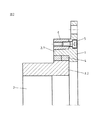
図2に示す、本発明の第2の実施例は、図1に示す第1の実施例とは、接続部材1と組み合わされたボスないしスリーブの形状が異なっている。ボス−スリーブ部材は、多部材で形成されており、第1のボス部分3.1は接続フランジ1と一体的に形成されており、かつブッシュ4の長さにわたって延びている。ボスの他の部分3.2は、スリーブ形状のボスコアとして形成されており、かつ軸端部2に対応づけられている。この実施例において、ブッシュ4はボスコアと直接協働し、ブッシュ4はこの実施例においては長さが短いために1回だけ分割されており、従って2つのリングからなっている。
【0013】
この実施例においても、ブロンズブッシュ4は短絡モーメントが発生した場合にスリップモーメントを吸収し、軸端部2とボスコア3はこのスリップモーメントに関与せず、ブッシュ4のリングの外側または内側の滑り面の過負荷が生じるだけである。その他の点では図1に示す実施例と機能が同一であることは別にして、図2に示す解決は、スリップモーメントの精度を±5%まで上昇させることができ、特にここでは実際の軸許容誤差に依存しないことを特徴としている。
【図面の簡単な説明】
【図1】 本発明に基づく軸−ボス結合の第1の実施例を示す側面図である。
【図2】 本発明に基づく軸−ボス結合の第2の実施例を同様に示す側面図である。
【符号の説明】
1…接続フランジ
2…軸端部
3…ボス−スリーブ部材
4…ブッシュ
5…締付けボルト
6…締付けリング[0001]
BACKGROUND OF THE INVENTION
The present invention has a connection flange and a fastening member, particularly a tightening ring, that can be fixed to the connection flange, and a shaft end that is associated with the connection flange absorbs a slip moment by the tightening ring. The present invention relates to a shaft-boss connection that can be connected to a connecting flange by frictional connection.
[0002]
[Prior art]
This type of shaft-boss coupling, which is known in practice, is used as overload protection, especially for high-frequency torque shocks, which occur in a short time. In this way, the coupled machine is protected from overload damage caused by torque impact. This is brought about by the fact that the bush arranged between the clamping member and the shaft end can absorb the slip moment, which causes the bush, especially formed as a bronze bush, in the connecting flange. The shaft and the associated boss member are not involved in this sliding process.
[0003]
When slipping occurs as a result of the occurrence of a short-circuit moment, wear usually occurs on one of the sliding surfaces of the bushing, and the bushing therefore has a suitable sliding surface on both its inner and outer sliding surfaces. Coated with a layer. However, an undesirable effect of this solution is that if the short-circuit moments occur frequently, all sliding surfaces are “eroded” and thus have a short lifetime.
[0004]
[Problems to be solved by the invention]
In view of the above problems, the present invention aims to improve an apparatus of the type mentioned at the outset so that the life of the shaft-boss connection is increased.
[0005]
[Means for Solving the Problems]
According to the present invention, this object is solved by the fact that the bush is formed of a plurality of portions in the axial direction in the shaft-boss connection described in the superordinate concept.
[0006]
The solution according to the invention consists of a number of axially divided bushes which form separate inner and outer sliding surfaces on a number of rings, each of which has a corresponding number of sliding surfaces. It is characterized by enabling an "erosion process" within.
[0007]
Other preferred embodiments emerge from the dependent claims.
[0008]
DETAILED DESCRIPTION OF THE INVENTION
Hereinafter, the present invention will be described in detail with reference to the drawings illustrating embodiments.
According to the first embodiment shown in FIG. 1, the shaft-boss connection has a
[0009]
The
[0010]
A bush made of bronze is arranged between the
[0011]
The level of slip moment to be absorbed by the bush in case of overload can be adjusted in advance. The accuracy of the pre-adjustment is about 10%. Variation of the slip moment is dependent on the actual tolerance of the
[0012]
The second embodiment of the present invention shown in FIG. 2 is different from the first embodiment shown in FIG. 1 in the shape of the boss or sleeve combined with the connecting
[0013]
Also in this embodiment, the bronze bushing 4 absorbs slip moment when the short-circuit moment is generated, does not participate in the
[Brief description of the drawings]
FIG. 1 is a side view showing a first embodiment of a shaft-boss coupling according to the present invention.
FIG. 2 is a side view similarly showing a second embodiment of the shaft-boss coupling according to the present invention.
[Explanation of symbols]
DESCRIPTION OF
Claims (4)
締付け要素(6)であって、該締付け要素(6)を前記接続フランジ(1)に対して締めつけるためのボルトを螺合的に受容し、該締付け要素(6)の最も内周側の面が前記ボス−スリーブ部材(3)の円錐状の面と楔的に接合していて、前記接続フランジ(1)に進入された軸の軸端部(2)が、該楔的接合により、接続フランジ(1)に摩擦結合せしめられている、締付け要素(6)と、
前記ボス−スリーブ部材(3)と前記軸端部(2)の間に配置され、スリップモーメントを吸収するブッシュ(4)であって、軸方向に多部材で構成されているブッシュ(4)とを具備し、
前記ボス−スリーブ部材(3)が前記締付け要素(6)の締め付け作用を受けており、
前記ブッシュ(4)により吸収されるスリップモーメントのレベルを予め設定できる、
ことを特徴とする軸−ボス結合。A connection flange (1) having a boss-sleeve member (3) formed integrally with the connection flange (1), and the radially outermost surface of the boss-sleeve member (3) A connecting flange (1), which is conical,
A tightening element (6), wherein a bolt for tightening the tightening element (6) against the connecting flange (1) is screwed and the innermost surface of the tightening element (6) Is joined to the conical surface of the boss-sleeve member (3) like a wedge, and the shaft end (2) of the shaft entering the connecting flange (1) is connected by the wedge-like joining. A clamping element (6) frictionally coupled to the flange (1);
A bush (4) disposed between the boss-sleeve member (3) and the shaft end (2) and absorbing a slip moment, the bush (4) being composed of multiple members in the axial direction; Comprising
The boss-sleeve member (3) is subjected to the clamping action of the clamping element (6);
The level of slip moment absorbed by the bush (4) can be preset.
A shaft-boss connection characterized by that.
Applications Claiming Priority (1)
| Application Number | Priority Date | Filing Date | Title |
|---|---|---|---|
| DE10231840A DE10231840B3 (en) | 2002-07-12 | 2002-07-12 | Shaft connection |
Related Child Applications (1)
| Application Number | Title | Priority Date | Filing Date |
|---|---|---|---|
| JP2008037409A Division JP4199297B2 (en) | 2002-07-12 | 2008-02-19 | Shaft-boss connection |
Publications (2)
| Publication Number | Publication Date |
|---|---|
| JP2004044805A JP2004044805A (en) | 2004-02-12 |
| JP4146304B2 true JP4146304B2 (en) | 2008-09-10 |
Family
ID=29719517
Family Applications (2)
| Application Number | Title | Priority Date | Filing Date |
|---|---|---|---|
| JP2003192776A Expired - Fee Related JP4146304B2 (en) | 2002-07-12 | 2003-07-07 | Shaft-boss connection |
| JP2008037409A Expired - Fee Related JP4199297B2 (en) | 2002-07-12 | 2008-02-19 | Shaft-boss connection |
Family Applications After (1)
| Application Number | Title | Priority Date | Filing Date |
|---|---|---|---|
| JP2008037409A Expired - Fee Related JP4199297B2 (en) | 2002-07-12 | 2008-02-19 | Shaft-boss connection |
Country Status (9)
| Country | Link |
|---|---|
| US (1) | US7156575B2 (en) |
| EP (1) | EP1380763B1 (en) |
| JP (2) | JP4146304B2 (en) |
| AT (1) | ATE305570T1 (en) |
| AU (1) | AU2003204695B2 (en) |
| DE (2) | DE10231840B3 (en) |
| DK (1) | DK1380763T3 (en) |
| ES (1) | ES2249653T3 (en) |
| HR (1) | HRP20030539B1 (en) |
Families Citing this family (10)
| Publication number | Priority date | Publication date | Assignee | Title |
|---|---|---|---|---|
| DE102005007525B3 (en) * | 2005-02-17 | 2006-08-31 | Atec-Weiss Gmbh & Co Kg | Shaft-hub connection with a slip torque receiving bushing |
| US20070204992A1 (en) * | 2006-01-13 | 2007-09-06 | Diversified Industries Ltd. | Polyurethane proppant particle and use thereof |
| DE102006018264B4 (en) * | 2006-04-20 | 2016-02-04 | Schaeffler Kg | bearing arrangement |
| DE102006035946A1 (en) * | 2006-07-31 | 2008-02-07 | A. Friedr. Flender Ag | shrink disc |
| DE202007010709U1 (en) * | 2007-08-01 | 2008-12-11 | Bikon-Technik Gmbh | Clamping arrangement and Abdrück- and cone ring for it |
| US8770885B2 (en) * | 2009-05-27 | 2014-07-08 | Melvin L. Myers | Wedge clamp |
| EP2674636A1 (en) | 2012-06-11 | 2013-12-18 | Siemens Aktiengesellschaft | Cam-shaft connection |
| ES2634649T3 (en) * | 2014-09-26 | 2017-09-28 | Siemens Aktiengesellschaft | Overload coupling |
| AT519938B1 (en) * | 2017-04-26 | 2019-02-15 | Miba Gleitlager Austria Gmbh | Method for producing a plain bearing bush |
| US11358243B2 (en) | 2018-04-25 | 2022-06-14 | Riverhawk Company | High torque friction fit low moment hub joint assembly for a shaft |
Family Cites Families (12)
| Publication number | Priority date | Publication date | Assignee | Title |
|---|---|---|---|---|
| DE7736362U1 (en) | Peter, Oskar E., 7129 Brackenheim | |||
| DE916370C (en) * | 1951-08-08 | 1954-08-09 | Star Kugelhalter Ges M B H Deu | Overload clutch |
| DE2031124C3 (en) * | 1970-06-24 | 1975-02-20 | Oskar E. 7129 Brackenheim Peter | Coupling for fastening a scar with an annular recess |
| ZA716150B (en) * | 1970-09-25 | 1973-04-25 | Massey Ferguson Ltd | Clutches |
| DE2252120C3 (en) * | 1972-10-24 | 1975-03-27 | Oskar E. 7129 Brackenheim Peter | Clamping set in double design for fastening a hub on a shaft |
| DE2734784C2 (en) * | 1977-08-02 | 1979-08-30 | Ralph 4041 Huelchrath Muellenberg | Clamping set |
| US4944379A (en) * | 1987-11-05 | 1990-07-31 | Dynamic Research And Development Corp. | Torque limiter |
| DE4118941C2 (en) * | 1991-06-08 | 1995-06-14 | Hartwig Dipl Ing Stuewe | Hub / shaft connection |
| US5328009A (en) * | 1993-01-11 | 1994-07-12 | General Motors Corporation | Engine starter drive shaft lubricator |
| US5599129A (en) * | 1995-01-17 | 1997-02-04 | Dcd Design & Manufacturing Ltd. | Load limited connector |
| US5970932A (en) * | 1997-12-02 | 1999-10-26 | Panzer | Rocker arm assembly |
| US6827673B2 (en) * | 2001-04-27 | 2004-12-07 | Razor Usa Llc | Collapsible pogo stick |
-
2002
- 2002-07-12 DE DE10231840A patent/DE10231840B3/en not_active Withdrawn - After Issue
-
2003
- 2003-05-17 DK DK03011281T patent/DK1380763T3/en active
- 2003-05-17 DE DE50301248T patent/DE50301248D1/en not_active Expired - Lifetime
- 2003-05-17 EP EP03011281A patent/EP1380763B1/en not_active Expired - Lifetime
- 2003-05-17 ES ES03011281T patent/ES2249653T3/en not_active Expired - Lifetime
- 2003-05-17 AT AT03011281T patent/ATE305570T1/en active
- 2003-06-13 AU AU2003204695A patent/AU2003204695B2/en not_active Ceased
- 2003-07-01 HR HR20030539A patent/HRP20030539B1/en not_active IP Right Cessation
- 2003-07-07 JP JP2003192776A patent/JP4146304B2/en not_active Expired - Fee Related
- 2003-07-10 US US10/617,119 patent/US7156575B2/en not_active Expired - Lifetime
-
2008
- 2008-02-19 JP JP2008037409A patent/JP4199297B2/en not_active Expired - Fee Related
Also Published As
| Publication number | Publication date |
|---|---|
| EP1380763B1 (en) | 2005-09-28 |
| ATE305570T1 (en) | 2005-10-15 |
| US20040105717A1 (en) | 2004-06-03 |
| ES2249653T3 (en) | 2006-04-01 |
| JP2008157467A (en) | 2008-07-10 |
| DK1380763T3 (en) | 2006-01-30 |
| EP1380763A1 (en) | 2004-01-14 |
| DE50301248D1 (en) | 2006-02-09 |
| AU2003204695B2 (en) | 2008-05-01 |
| JP2004044805A (en) | 2004-02-12 |
| AU2003204695A1 (en) | 2004-01-29 |
| HRP20030539B1 (en) | 2006-02-28 |
| US7156575B2 (en) | 2007-01-02 |
| DE10231840B3 (en) | 2004-01-08 |
| HRP20030539A2 (en) | 2005-02-28 |
| JP4199297B2 (en) | 2008-12-17 |
Similar Documents
| Publication | Publication Date | Title |
|---|---|---|
| JP4199297B2 (en) | Shaft-boss connection | |
| US4183719A (en) | Composite impeller wheel with improved centering of one component on the other | |
| JP4339782B2 (en) | Fixing device for fixing the impeller to the shaft | |
| KR101534091B1 (en) | Attachment arrangement for composite wheels | |
| US4684280A (en) | Clevis connection | |
| US5850895A (en) | Metallic aircraft brake disk having thermal relief slots | |
| JPS6048651B2 (en) | Mounting device | |
| JP2009299754A (en) | Bearing joining structure and bearing joining member | |
| JP2008545107A (en) | Prestressed shaft / hub combination with perfect conical shape | |
| US4781654A (en) | Resilient shaft coupling | |
| JP4979883B2 (en) | Vacuum pump with high-speed rotor | |
| CN102562835B (en) | Shrink disc for friction-type connection of rotating machine components | |
| US5779416A (en) | Bolt/stud and nut for enhanced high-cycle fatigue capability | |
| JPH0579846B2 (en) | ||
| US6663343B1 (en) | Impeller mounting system and method | |
| CA1086970A (en) | Zero clearance coupling | |
| CN109236880B (en) | Torque limiting type coupler | |
| WO1990002272A2 (en) | Shaft positioning and coupling device | |
| US6234910B1 (en) | Shaft coupling arrangement | |
| US2879650A (en) | Flexible coupling | |
| AU2002217263B2 (en) | Pipe coupling | |
| CA1085639A (en) | Thrust cancelling shaft coupling | |
| JP4416099B2 (en) | Elastic shaft coupling | |
| US3233427A (en) | Shaft coupling | |
| JPS624926A (en) | Shaft joint of rotary machine |
Legal Events
| Date | Code | Title | Description |
|---|---|---|---|
| A621 | Written request for application examination |
Free format text: JAPANESE INTERMEDIATE CODE: A621 Effective date: 20050418 |
|
| A977 | Report on retrieval |
Free format text: JAPANESE INTERMEDIATE CODE: A971007 Effective date: 20070627 |
|
| A131 | Notification of reasons for refusal |
Free format text: JAPANESE INTERMEDIATE CODE: A131 Effective date: 20070703 |
|
| A521 | Request for written amendment filed |
Free format text: JAPANESE INTERMEDIATE CODE: A523 Effective date: 20070927 |
|
| A02 | Decision of refusal |
Free format text: JAPANESE INTERMEDIATE CODE: A02 Effective date: 20071023 |
|
| A521 | Request for written amendment filed |
Free format text: JAPANESE INTERMEDIATE CODE: A523 Effective date: 20080219 |
|
| A521 | Request for written amendment filed |
Free format text: JAPANESE INTERMEDIATE CODE: A523 Effective date: 20080131 |
|
| A911 | Transfer to examiner for re-examination before appeal (zenchi) |
Free format text: JAPANESE INTERMEDIATE CODE: A911 Effective date: 20080303 |
|
| TRDD | Decision of grant or rejection written | ||
| A01 | Written decision to grant a patent or to grant a registration (utility model) |
Free format text: JAPANESE INTERMEDIATE CODE: A01 Effective date: 20080520 |
|
| A01 | Written decision to grant a patent or to grant a registration (utility model) |
Free format text: JAPANESE INTERMEDIATE CODE: A01 |
|
| A61 | First payment of annual fees (during grant procedure) |
Free format text: JAPANESE INTERMEDIATE CODE: A61 Effective date: 20080619 |
|
| R150 | Certificate of patent or registration of utility model |
Ref document number: 4146304 Country of ref document: JP Free format text: JAPANESE INTERMEDIATE CODE: R150 Free format text: JAPANESE INTERMEDIATE CODE: R150 |
|
| FPAY | Renewal fee payment (event date is renewal date of database) |
Free format text: PAYMENT UNTIL: 20110627 Year of fee payment: 3 |
|
| S111 | Request for change of ownership or part of ownership |
Free format text: JAPANESE INTERMEDIATE CODE: R313113 |
|
| FPAY | Renewal fee payment (event date is renewal date of database) |
Free format text: PAYMENT UNTIL: 20110627 Year of fee payment: 3 |
|
| R350 | Written notification of registration of transfer |
Free format text: JAPANESE INTERMEDIATE CODE: R350 |
|
| FPAY | Renewal fee payment (event date is renewal date of database) |
Free format text: PAYMENT UNTIL: 20110627 Year of fee payment: 3 |
|
| FPAY | Renewal fee payment (event date is renewal date of database) |
Free format text: PAYMENT UNTIL: 20110627 Year of fee payment: 3 |
|
| FPAY | Renewal fee payment (event date is renewal date of database) |
Free format text: PAYMENT UNTIL: 20120627 Year of fee payment: 4 |
|
| R250 | Receipt of annual fees |
Free format text: JAPANESE INTERMEDIATE CODE: R250 |
|
| FPAY | Renewal fee payment (event date is renewal date of database) |
Free format text: PAYMENT UNTIL: 20130627 Year of fee payment: 5 |
|
| R250 | Receipt of annual fees |
Free format text: JAPANESE INTERMEDIATE CODE: R250 |
|
| R250 | Receipt of annual fees |
Free format text: JAPANESE INTERMEDIATE CODE: R250 |
|
| R250 | Receipt of annual fees |
Free format text: JAPANESE INTERMEDIATE CODE: R250 |
|
| R250 | Receipt of annual fees |
Free format text: JAPANESE INTERMEDIATE CODE: R250 |
|
| R250 | Receipt of annual fees |
Free format text: JAPANESE INTERMEDIATE CODE: R250 |
|
| R250 | Receipt of annual fees |
Free format text: JAPANESE INTERMEDIATE CODE: R250 |
|
| S111 | Request for change of ownership or part of ownership |
Free format text: JAPANESE INTERMEDIATE CODE: R313113 |
|
| R350 | Written notification of registration of transfer |
Free format text: JAPANESE INTERMEDIATE CODE: R350 |
|
| R250 | Receipt of annual fees |
Free format text: JAPANESE INTERMEDIATE CODE: R250 |
|
| R250 | Receipt of annual fees |
Free format text: JAPANESE INTERMEDIATE CODE: R250 |
|
| R250 | Receipt of annual fees |
Free format text: JAPANESE INTERMEDIATE CODE: R250 |
|
| R250 | Receipt of annual fees |
Free format text: JAPANESE INTERMEDIATE CODE: R250 |
|
| LAPS | Cancellation because of no payment of annual fees |