JP4146018B2 - Fuel injection device - Google Patents
Fuel injection device Download PDFInfo
- Publication number
- JP4146018B2 JP4146018B2 JP00182699A JP182699A JP4146018B2 JP 4146018 B2 JP4146018 B2 JP 4146018B2 JP 00182699 A JP00182699 A JP 00182699A JP 182699 A JP182699 A JP 182699A JP 4146018 B2 JP4146018 B2 JP 4146018B2
- Authority
- JP
- Japan
- Prior art keywords
- valve
- pressure
- fuel
- needle valve
- chamber
- Prior art date
- Legal status (The legal status is an assumption and is not a legal conclusion. Google has not performed a legal analysis and makes no representation as to the accuracy of the status listed.)
- Expired - Fee Related
Links
Images


Landscapes
- Fuel-Injection Apparatus (AREA)
Description
【0001】
【発明の属する技術分野】
本発明は、燃料噴射弁の開弁圧を調整可能とした燃料噴射装置、特にソレノイド駆動のポペット弁によって燃料噴射時期を調整する電磁式ユニットインジェクタからなる燃料噴射装置に関する。
【0002】
【従来の技術】
図4〜図5は、内燃機関用電磁式ユニットインジェクタの従来技術の一例を示し、図4はその要部縦断面図、図5は作動説明図である。
【0003】
図4において、3は本体で、これのプランジャ孔3jにはプランジャ1が往復摺動自在に嵌合され、上部のタペット孔5aにはタペット5が往復摺動自在に嵌合されている。
前記プランジャ1は、タペット5の上端係合部に係合されて該タペット5とともに往復動するようになっている。6は戻しスプリングで、上記プランジャ1及びタペット5を上方に戻すように付勢されている。
前記タペット5はロッカアーム(不図示)を介して燃料カム(不図示)に連結され、該燃料カムによってプランジャ1及びタペット5が一体で前記戻しスプリング6の弾力に抗して往復動するようになっている。
【0004】
3aはプランジャ室で、前記プランジャ1の頂面が臨み、これに導入される燃料を加圧するようになっている。
11は燃料噴射ノズル、9はスプリングケージ、4はスペーサであり、該燃料噴射ノズル11のノズルボデー11a、スプリングケージ9及びスペーサ4はノズルナット7を本体3の下部のねじにねじ込むことにより、該本体3に強固にかつ流体密に固定されている。
【0005】
前記本体3の、前記プランジャ1挿入用の孔3jの側方にはポペット弁孔3fが穿設され、該ポペット弁孔3fにはポペット弁2が往復動可能に嵌合されている。
3gは前記ポペット弁孔3fの下方に連設された下部孔である。また、前記ポペット弁孔3fの上部にはポペット弁2の弁座3hが設けられている。
3pは前記下部孔3g内に形成された燃料溜で、該燃料溜3pは本体3の下面にボルト2bによって固定された蓋18及び下部孔3gによって区画形成されている。
【0006】
前記ポペット弁2の下方には移動制限機能を有する蓋18がボルトにより固定されている。前記蓋18の上面は前記下部孔3gとともに上記のように燃料溜3pを形成している。該燃料溜3pには本体3の下部の燃料溜24から本体内の供給通路3dを経て燃料が供給されるようになっている。この燃料は後述する排油通路3eを経て燃料タンク(不図示)へ排出されるようになっている。前記弁座3hの上部には排油溜3cが形成されており、前記燃料溜3pと排油溜3cの間には連通路3kが開けられ、両溜間の圧力が均等化されるようになっている。
【0007】
前記プランジャ室3aへの燃料の出入りのための燃料通路3bは一端が前記ポペット弁孔3fの環状円錐形の弁座3hよりも所定距離下方に開口している。前記排油溜3cと前記燃料通路3bとの間の燃料流はソレノイド作動の前記ポペット弁2により制御される。
3eは排油孔で、前記連通路3kを介して前記燃料溜3p及び排油溜3cに連通されている。
【0008】
前記ポペット弁2は円錐形の弁フェース2mをそなえ、摺動部2bと、上方に延びる弁軸部2cとにより形成されている。該摺動部2bの周囲にはポペット弁2の開閉運動時に燃料通路3bと排油溜3cを連通する環状溝21が本体3内に設けられている。前記ポペット弁2の弁軸部2cの上端面はアーマチュア室13aに開放され、該上端面には長方形のアーマチュア13が締付け固定されており、該アーマチュア13には、これの運動時に燃料を通過させるため複数の孔23が穿けられている。
【0009】
また、前記ポペット弁2は円錐形の弁フェース2mの上方に肩部を形成し、ここに下部ばね受け26が係合されている。該下部ばね受け26の上方にはポペット弁2を開放させる方向に付勢されたスプリング15と該スプリング15を固定し制限する上部ばね受け27とが設置されている。12はソレノイドステータであり、該ソレノイドステータ12はソレノイドスペーサ14を介してボルト22により本体3に締付け固定されている。
【0010】
ソレノイドステータ12は、例えば合成樹脂材からなるソレノイドケース12d、ソレノイドコイル12cを保持するコイルボビン12bと磁気回路を構成するE字形コア12aより構成されている。前記ソレノイドコイル12cと本体3の間には前記アーマチュア13が設置されている。図はポペット弁2が閉鎖した状態を示しており、この状態ではソレノイドステータ12とアーマチュア13の対向する作動面の間には最小隙間(0.05mm〜0.3mm程度)が存在する。
【0011】
また、前記ポペット弁2の開放状態では、該ポペット弁2の下端面2aが蓋18の上面に当接している。該蓋18は前記ポペット弁2との当接状態において、該ポペット弁2の空洞部2pと燃料溜3pとを連通させる通路(孔もしくは溝)18cを有する。
【0012】
前記ソレノイドコイル12cは一対の端子が接続されており、この端子には電気配線によりソレノイド制御装置31(燃料噴射電子制御回路)及び電源に接続されている。また、該ソレノイド制御装置31には、エンジン回転速度、油温、給気圧等を検出する検出器32が接続されている。
【0013】
かかる従来の電磁式ユニットインジェクタにおいて、エンジンの運転中、燃料タンクからの燃料が、燃料ポンプ及び燃料パイプを経てシリンダヘッド内燃料供給通路より、本体3下部の燃料溜24に所定の比較的低い圧力で供給される。該燃料溜24に供給された燃料は、本体3内の供給通路3dを経て燃料溜3pに供給され、さらに排油路3eを経て、燃料タンクへ排出される。
【0014】
図5(A)はプランジャ1が下降している状態を示し、ポペット弁2が閉じるとプランジャ室3aに充填された燃料は加圧され、スペーサ4の燃料通路4aを通過して噴射ノズル11に嵌合された針弁10を開弁させ、燃料噴射が始まる。次いで図5(B)に示すように、ポペット弁2が開くと、プランジャ1により加圧されていたプランジャ室3a内の燃料は燃料通路3bへ押し出されて、燃料噴射は終了する。さらに図5(C)に示すように、プランジャ1が下降より上昇に転ずると、プランジャ室3aへ燃料通路3bを介して供給圧(通常1〜6Kgf/cm2)に加圧された燃料が流入し、充填され、これにより燃料噴射の1サイクルが終了する。
【0015】
図6には、図4〜図5に示す従来の電磁式ユニットインジェクタのソレノイド制御装置によるポペット弁の開閉制御ブロック図である。
図6において、エンジン回転数、アクセル量(アクセル踏み込み量、あるいは燃料ラック移動量でも可)、給気圧力、水温、油温、排気温度等の各部温度は、夫々エンジン回転数検出器101、アクセル量検出器102、給気圧力検出器103、温度検出器104等によって検出され、ソレノイド制御装置31の入力装置106に受け入れられる。
【0016】
上記各検出信号は、入力装置106からソレノイド制御部108に入力される。
107は噴射時期設定部で、上記エンジン回転数、アクセル量等の運転状態と燃料噴射時期との関係が設定されている。
ROMは読み出し専用メモリ、RAMは読み出し、読み込み両用のメモリである。
【0017】
ソレノイド制御部108においては、前記運転状態の検出信号と前記噴射時期設定部に設定された燃料噴射時期とを突合せて、該運転状態の検出値に適合する燃料噴射時期を求め、該噴射時期に対応するポペット弁2の開閉時期を算出し、前記E字形コア12a、コイルボビン12b、ソレノイドコイル12c等からなるソレノイド装置12に出力する。
該ソレノイド装置12は、前記のようにして入力された開閉時期に従い、ポペット弁2を開閉制御する。
【0018】
【発明が解決しようとする課題】
図4〜図6に示すような従来技術に係る電磁式ユニットインジェクタにおいては、ソレノイド制御装置31に入力されるエンジン回転数、アクセル量等のエンジン運転状態の検出信号に基づき、該ソレノイド制御装置31において、上記運転状態に適合する燃料噴射時期を算出し、該噴射時期になるようにソレノイド装置12を介してポペット弁2を開閉制御している。
【0019】
一方、かかる従来技術においては、針弁10の開弁圧は針弁スプリング8のセット荷重によって一義的に求められており、エンジンの運転状態に無関係に一定となる。また、燃料噴射モード(噴射圧の変化状況)は、プランジャ1を駆動する燃料カム(不図示)の形状によって一義的に定まる。
【0020】
即ち、図9には、上記従来技術に係る電磁式ユニットインジェクタ(図4参照)のポペット弁2及び針弁10の作動線図を示しており、(A)は燃料カム(不図示)のカム速度、(B)はソレノイドステータ12におけるポペット弁制御電流、(C)はポペット弁2のリフト、(D)は噴射圧、(E)は針弁10のリフトである。
【0021】
またt1 はポペット弁2の閉方向へのリフト始め、t2 はポペット弁2の閉止及び噴射圧Pの上昇始め、t3 はソレノイド電流の整定時期(低下時期)、t4 はソレノイド電流遮断、t5
はポペット弁2の閉止、t6 は針弁10のリフト始め、t7
は針弁閉止の時刻を夫々示す。
【0022】
図9に示すように、かかる従来技術にあっては、t2にてポペット弁2が閉じて噴射圧が上昇し始め、針弁10に作用するプランジャ室3aからの燃料の圧力が開弁圧P1に達すると針弁10が開き、燃料噴射ノズル11から燃焼室(不図示)内に燃料が噴射されるが、針弁10の開弁圧は上記のように一定であり、噴射圧のモードは燃料カムによって一義的に定まるため、ポペット弁2による噴射時期を制御のみが可能であって、噴射圧の制御は不可能であるため、エンジンの運転状態に対応して噴射圧を上昇させることは不可能となり、高圧噴射により、高い燃焼効率、及び燃料消費率の低下がなされたエンジンを得るのは困難となっている。
【0023】
本発明はかかる従来技術の課題に鑑み、燃料噴射時期と噴射圧の制御を、双方を関連させて容易になし得、これによって高圧噴射を実現し、燃焼効率が向上され、燃料消費率の低下が実現できる燃料噴射装置を提供することを目的とする。
【0024】
【課題を解決するための手段】
本発明はかかる課題を解決するため、請求項1記載の発明として、燃料をシリンダ内に噴射する噴孔を備えた燃料噴射ノズルと、該燃料噴射ノズルに往復摺動可能に嵌合された針弁と、該針弁を閉弁方向に押圧する針弁スプリングと、クランク軸に連動されるタペットにより本体内を往復摺動せしめられプランジャ室内に供給された燃料を加圧し、燃料通路を経て前記針弁に送り、該針弁の下端部に作用させてこれを開弁するプランジャとを備えた燃料噴射装置において、前記本体の下端部に前記針弁スプリングが収納されるスプリングケージを取付け、前記針弁の上面が臨み該針弁を閉弁方向に加圧する前記プランジャ室からの燃料である作動油が収容される油室を前記針弁スプリングが収納される室によって構成し、該油室と前記プランジャ室とをプランジャ軸方向に延びる連通路で接続し、該連通路の途中で分岐して排油路に接続される排出通路を設け、前記油室、連通路および排出通路を前記スプリングケージ内に形成し、さらに該排出通路を開閉する開閉弁及び該開閉弁を開閉制御する弁制御装置をそなえて該油室内の作動圧力を調整する圧力調整手段を前記スプリングケージ内に設け、前記針弁は該針弁の下端部に作用する燃料の圧力が前記針弁スプリングによる圧力と前記圧力調整手段によって調整される油室内の作動油圧力との和よりも大きくなったとき開弁し、かつ前記針弁スプリングによる圧力と油室内の作動油圧力との和が針弁の下端部に作用する燃料の圧力よりも大きくなったとき閉弁するように構成され、さらに、前記弁制御装置には前記燃料通路と排油路との間に設けられたポペット弁を駆動するソレノイド装置に開閉信号を出力して燃料噴射時期を制御するソレノイド制御部と、前記圧力調整手段に開閉信号を出力して開弁圧力を制御する開弁圧制御部とを備え、前記開弁圧制御部は前記ポペット弁が閉じてから前記開閉弁が開くまでの時間を変化させることによって前記開弁圧力を制御するように構成したことを特徴とする燃料噴射装置を提案する。
かかる発明によれば、ソレノイド制御部で燃料噴射時期の制御が、開弁圧制御部で開弁圧力の制御が可能となる。
開弁圧制御部において、エンジン運転状態の検出値と、該運転状態に対応する基準開弁圧とを突合せて該運転状態の検出値に適合する開弁圧になるような開閉弁の開閉時期を求めて圧力調整手段(例えば圧電素子)に出力する。該弁制御装置においては、前記開閉時期に開閉弁を開閉せしめる。
従って、かかる発明によれば、エンジンの運転状態に対応して開閉弁の開閉時期を制御することが可能となり、エンジンの運転状態に適合した開弁圧を得ることができ、エンジンの高出力域における高圧噴射を実現できる。
すなわち、開弁圧制御部は前記ポペット弁が閉じてから前記開閉弁が開くまでの時間を変化させることによって前記開弁圧力を調整して燃料噴射圧力を制御するこが可能となる。
【0025】
【0026】
【0027】
【0028】
また好ましくは、請求項2に記載のように、前記圧力調整手段は圧電素子からなる。
【0029】
かかる発明によれば、針弁の上面が臨む油室内に加圧された作動油が導入され、この作動油の圧力が針弁の上面に該針弁の閉弁方向に作用することにより、針弁の開弁圧は前記油室内の圧力と針弁スプリングのセット荷重による圧力との和となり、従来技術に較べて高い開弁圧となる。
【0030】
該開弁圧は、圧力調整手段によって開閉弁の開閉時期を変化させることにより、油室内の圧油の排油時期を変化させて調整する。
【0031】
また、前記油室内の作動油を排出して油室内の圧力を解放すれば、従来技術と同様な針弁スプリングのセット荷重のみによって開弁圧の設定も可能となる。
【0032】
これによって燃料噴射弁の噴射圧が上昇して噴霧の微粒化が促進されて燃焼効率が向上し、黒煙の発生が低減される。
【0033】
【0034】
【0035】
【0036】
【0037】
【0038】
請求項3記載の発明は、前記連通路は、前記排出通路との交叉部よりも前記プランジャ室側にある上部連通路と、該交叉部よりも前記油室側にある下部連通路よりなり、前記上部連通路の内径をd1、前記下部連通路の内径をd2、前記排出通路の内径をd3としたとき、
d2 2>d1 2
で、かつ、
d3 2>(d1 2+d2 2)
に設定されてなる。
【0039】
さらに請求項4記載の発明は、前記連通路は、前記排出通路との交叉部よりも前記プランジャ室側にある上部連通路と、該交叉部よりも前記油室側にある下部連通路よりなり、
前記上部連通路の内径をd1、長さをL1、前記下部連通路の内径をd2、長さをL2 としたとき、
d1≒d2
のとき、
L1>L2
に設定されてなる。
【0040】
かかる発明によれば、油室内に圧油を供給することにより、開弁圧を上昇させた後、開閉弁を開放すると、前記上部連通路の直径d1あるいは長さL1と下部連通路の直径d2あるいは長さL2との関係が上記のように設定されているので、上部連通路の流路抵抗が下部連通路よりも大きくなり、かつ、排出通路の通路面積が上部、下部連通路のそれよりも大きく構成されているので、油室内の圧油を円滑に排出通路から排出することができ、開弁圧の制御を正確にかつ高い応答性で以てなすことができる。
【0041】
【発明の実施の形態】
以下、図面を参照して本発明の好適な実施形態を例示的に詳しく説明する。但しこの実施形態に記載されている構成部品の寸法、材質、形状、その相対的配置等は特に特定的な記載がないかぎりは、この発明の範囲をそれに限定する趣旨ではなく、単なる説明例にすぎない。
【0042】
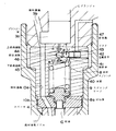
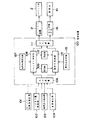
図1は本発明の実施形態に係る電磁式ユニットインジェクタの縦断面図、図2は針弁の開弁圧調整部の拡大断面図、図3はポペット弁の開閉及び開弁圧の制御ブロック図である。
【0043】
図1〜図2において、3は本体で、これのプランジャ孔3jにはプランジャ1が往復摺動自在に嵌合され、上部のタペット孔5aにはタペット5が往復摺動自在に嵌合されている。前記プランジャ1は、タペット5の下端係合部の係合溝5bに上下を拘束されて該タペット5とともに往復動するようになっている。
【0044】
6は戻しスプリングで、上記プランジャ1及びタペット5を上方に戻すように付勢されている。
前記タペット5はロッカアーム(不図示)を介して燃料カム(不図示)に連結され、該燃料カムによってプランジャ1及びタペット5が一体で前記戻しスプリング6の弾力に抗して往復動するようになっている。
【0045】
3aはプランジャ室で、前記プランジャ1の頂面が臨み、これに導入される燃料を加圧するようになっている。
3bは前記本体3に穿設された燃料通路で、前記プランジャ室3aに連通されている。
3dは前記本体3に設けられた燃料の供給通路で、その開口部が前記プランジャ1により開閉されるようになっている。
11は燃料噴射ノズルで、ノズルボデー11aと該ノズルボデー11a内に往復摺動自在に嵌合された針弁10からなる。
前記ノズルボデー11aの先端部には燃料溜11c及び燃料噴射用の複数の噴孔11bが設けられている。10aは、下端が該燃料溜11cに開口される燃料通路である。
【0046】
9はスプリングケージ、4はスペーサであり、該スプリングケージ9、スペーサ4及び前記ノズルボデー11aはノズルナット7aによって前記本体3の下部に螺着されて、前記各部材間の接合面35,36を流体密に圧接している。
【0047】
8は前記スプリングケージ9内に収納された針弁スプリングで、前記本体3の下面と前記針弁10の頭部に当接されるばね受8aとの間に介装され、所定のセット荷重(取付荷重)、即ち後述するような前記針弁10の開弁圧に相当するセット荷重で以て取付けられている。
10aは前記スプリングケージ9内に穿設された燃料通路で、下端が前記ノズルボデー11a内の燃料通路10aに連通されるとともに、上端が前記プランジャ室3aに連通されている。
【0048】
前記本体3の、前記プランジャ1が嵌合されるプランジャ孔3jの側方にはポペット弁孔3fが設けられ、該ポペット弁孔3fには中空の弁ケース30が挿入されている。
37はスプリングケースで、前記本体3のポペット弁孔3fの上部のねじ部に螺合されて、前記弁ケース30をその上下接合面39,38にて流体密になるように押し込んでいる。
【0049】
2はポペット弁で、前記弁ケース30の内周に往復摺動自在に嵌合されるとともに、円錐形の弁フェース2mを備え、該弁フェース2mと該弁ケース30のシート部3hとが当接されたとき閉弁し、該弁フェース2mとシート部3hとが離れたとき開弁するようになっている。
【0050】
15は前記ポペット弁2の戻し用のスプリングで、前記スプリングケース37に形成された排油溜3c内に収納され、該スプリングケース37の支持面と前記ポペット弁2の支持面2hとの間に介装され、該ポペット弁2を開弁する方向に付勢されている。
2nは前記ポペット弁2の外周に形成された燃料溝、30bは前記ポペット弁2のシート部3hと弁フェース2mとのシート部に連なる燃料溝で、双方の燃料溝2nと30bとの間を前記ポペット弁2の開閉によって連通あるいは遮断するようになっている。
【0051】
3bは前記本体3に設けられた燃料通路、30cは前記弁ケース30に設けられ、前記燃料溝30bに連通される燃料通路で、双方の燃料通路30c,3bは前記プランジャ室3aに連通されている。
【0052】
また、30eは前記弁ケース30に円周方向に沿って複数個設けられた排油路で、該排油路30eは本体3に設けられた排油路(排油出口)3eに連通されている。
前記排油路3e,30e及びスプリング15が収納される排油溜3cは微小通路を介して後述するアーマチュア室13aに連通され、ポペット弁2に不要な残圧が掛からないようにしている。
【0053】
前記ポペット弁2の上方に延びる弁軸部2cの上端部には磁性体からなるアーマチュア13がナット2qによって固着されている。
該アーマチュア13は、例えばアルミ等の非磁性材料からなるスペーサ14に形成された前記アーマチュア室13a内に収納されている。
【0054】
12はソレノイド装置で、次のように構成されている。12aは、例えば合成樹脂材等の非電導材料からなるソレノイドケースで、前記スペーサ14とともに前記本体3の上面に複数のボルト(不図示)によって固着されている。
14はスペーサ、12aはE字形コアで、該E字形コア12aの内部にはソレノイドコイル12cを保持するコイルボビン12bが収納されて磁気回路を構成している。
図1は前記ソレノイドコイル12cの電流が遮断され、スプリング15の弾力でポペット弁2が開弁している状態を示している。
【0055】
前記ソレノイドコイル12cには、図3に示す制御装置100のソレノイド制御部108からの制御信号が入力されるようになっている(詳細は後述する)。
【0056】
また、前記針弁スプリング8が収納される室は油室40となっており、該油室40は下部連通路45及び上部連通路44を介して前記プランジャ室3aに連通されている。
そして、該上部連通路44と下部連通路45との接続部からは排出通路46が分岐され、該排出通路46は後述する開閉弁41を介して排油路47に接続されている。
【0057】
図2に示すように、前記上部連通路44、下部連通路45及び排出通路46の直径を夫々d1,d2,d3とすると、これらの大きさの関係は次のように設定されている。
d2 2>d1 2
で、かつ、
d3 2>(d1 2+d2 2) ……(1)
【0058】
あるいは、上記(1)式に代えて、前記上部連通路44の長さをL1、下部連通路45の長さをL2とすると、上記d1≒d2として、L1>L2のように構成してもよい。
【0059】
図1、図2において、41は前記排出通路46を開閉する球形弁からなる開閉弁、42は該開閉弁41を開閉駆動する圧電素子、43は該圧電素子42を取付けるためのプラグである。
後述する圧力調整手段116(図3参照)を構成する前記圧電素子42は周知の部材で、電圧に応じて伸縮することにより、これに取付けられた前記開閉弁41を開閉するものであり、後述する制御装置100から制御電圧が供給されるようになっている。
【0060】
尚、前記圧電素子42に代えて、次の手段によって前記開閉弁41を開閉するようにしてもよい。
その第1の手段は、磁歪素子に前記開閉弁41を取付け、外部から該磁歪素子に与える磁力を変化させることにより、その長さを変化させ、前記開閉弁41を開閉するように構成する。
【0061】
また、第2の手段は、前記開閉弁41をソレノイドによって開閉できる弁に構成し、該ソレノイドに通電あるいは遮断することにより、該開閉弁を開閉するように構成する。
【0062】
かかる構成からなる電磁式ユニットインジェクタを備えたエンジンの運転時において、燃料ポンプ及び燃料パイプを経てシリンダヘッド内燃料供給通路より本体3下部の燃料溜24に所定の比較的低い圧力(1〜6Kgf/cm2程度)で燃料が供給される。該燃料溜24に供給された燃料は、本体3内の供給通路3dに導かれる。
【0063】
そして、前記タペット5の戻し用のスプリング6の弾力により、該タペット5を介してプランジャ1が上昇して、該プランジャ1の下端縁が供給通路3dを開き、かつ後述するようにソレノイド装置12とアーマチュア13との共働によりポペット弁2が開かれると、該供給通路3d内の燃料がプランジャ室3a内に導入される。
【0064】
次に図1〜図4を参照して、ソレノイド装置12、及びこれによって駆動されるポペット弁2の作動を説明するに、後述する制御装置100からの制御信号によってソレノイドコイル12cが通電されると、電圧V1によりソレノイド磁気回路に磁束が発生し、ソレノイド装置12とアーマチュア13との間に電磁吸引力Fcが発生するが該電磁吸引力Fcがポペット弁2のスプリング15のセット荷重よりも大きくならないとアーマチュア13とポペット弁2の結合体は上方へ動き出さない。
【0065】
時刻t2に前記電磁吸引力Fcがスプリング15のセット荷重より大きくなると図5(c)に示すように、アーマチュア13がソレノイド装置12側の吸引力Fcによって吸引され、ポペット弁2は上昇(リフト)し、時刻t3になると該ポペット弁2の弁座3hに着座し、弁開口部は閉鎖される。
その後、ソレノイドコイル12cの駆動電圧は、図5(a)に示すように、ポペット弁2を閉鎖保持するに必要な電圧V2へ低下せしめられる。
【0066】
一方、プランジャ1は、タペット5を介して下降せしめられており、該プランジャ1の下端面3a1が前記供給通路3dを閉じ、さらに前記のようにしてソレノイドコイル12cが通電されてアーマチュア13がE字形コア12aに吸引されてポペット弁2が閉じると、プランジャ室3a及びこれに通ずる燃料通路3b,30c,10a及び燃料溜11c等は密閉となって圧力が上昇する。
そして該圧力、即ち燃料溜11c内の圧力が、後述するように前記油室40内の油圧と針弁スプリング8のセット荷重による圧力との和に打ち勝つと、該針弁10が開弁し、プランジャ室3a内から燃料通路10aを経て燃料溜11cに導かれていた燃料が噴孔11bからエンジンの燃焼室(不図示)内に噴射される。
【0067】
次に図3に示す制御ブロック図を参照して、この実施形態に係る電磁式ユニットインジェクタにおけるポペット弁2の開閉制御及び針弁10の開弁圧の制御について説明する。
図3において、エンジン回転数、アクセル量(アクセル踏み込み量、あるいは燃料ラック移動量でも可)、給気圧力、水温、油温、排気温度等の各部温度は、夫々エンジン回転数検出器101、アクセル量検出器102、給気圧力検出器103、温度検出器104等によって検出され、制御装置100の入力装置106に受け入れられる。
【0068】
前記各検出信号は入力装置106からソレノイド制御部108及び開弁圧制御部114に入力される。
107は噴射時期設定部で、上記エンジン回転数、アクセル量等の運転状態と燃料噴射時期との関係が設定されている。
ROMは読み出し専用メモリ、RAMは読み出し、読み込み両用のメモリである。
【0069】
前記ソレノイド制御部108においては、図6に示す従来技術と同様に前記運転状態の検出信号と前記噴射時期設定部に設定された燃料噴射時期と突合せて、該運転状態の検出値に適合する燃料噴射時期を求め、該噴射時期に対応するポペット弁2の開閉時期を算定し、前記E字形コア12a、コイルボビン12b、ソレノイドコイル12c等からなるソレノイド装置12に出力する。
該ソレノイド装置12は前記のようにして入力された開閉時期に従い、ポペット弁2を開閉制御する。
【0070】
一方、115は開弁圧設定部で、上記エンジン回転数、アクセル量等のエンジン運転状態と針弁10の開弁圧との関係が設定されている。
前記開弁圧制御部114においては、前記入力装置106を経て入力された運転状態の検出信号と前記開弁圧設定部115に設定されている運転状態に対応する基準開弁圧とを突合せて、該運転状態の検出値に適合する開弁圧になるような開閉弁41の開閉時期を求め、圧電素子42の電圧として圧力調整手段116に入力する。
【0071】
圧力調整手段116においては、これに入力された電圧値を圧電素子42に与える。該圧電素子42は、上記電圧値に従い伸縮して、前記開閉弁41の開度を変化させる。
【0072】
ここで、前記のように油室40にはプランジャ室3aから上部連通路44及び下部連通路45を経て燃料が導入されており、前記のようにしてプランジャ1の下降中ポペット弁2が閉じ、さらに前記開閉弁41が閉じるとプランジャ室3a内の高圧燃料が上部、下部連通路44,45を経て導入されて針弁10の上面に作用し、該針弁10を閉弁方向に押圧する。
即ち、前記ポペット弁2及び開閉弁41の双方の閉弁時には、前記油室40にはオリフィス機能を有する最小径(d1<d2)の上部連通路44の面積=(πd1 2)/4で決まる油圧P1が発生し、この油圧P1と針弁スプリング8の開弁圧Pとの合力が、針弁10の開弁圧となり、高い噴射圧が得られる。
【0073】
また、前記開弁圧制御部115からの開弁圧制御信号に基づく電圧が減少して、圧力調整手段116によって圧電素子42が収縮せしめられ、開閉弁41が開弁すると、上部連通路44、下部連通路45及び排出通路46の面積の関係が前記(1)式のように設定されているので、油室40内の圧油は下部連通路45から排出通路46に入り、開閉弁41を通って排油路47に円滑に排出される。
これにより、針弁10の開弁圧は針弁スプリング8のセット荷重による開弁圧(従来技術と同様な開弁圧)に低下せしめられる。
【0074】
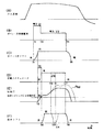
次に、図7〜図8に示すタイムチャートにおいて、(A)は燃料カム(不図示)の速度、(B)はソレノイド装置12により出力されるソレノイド制御電流、(C)はポペット弁2のリフト、(D)は圧電素子42からなる圧電アクチュエータの変位、(E)は噴射圧、(F)は針弁リフトの時間変化を夫々示す。
【0075】
図7において、ポペット弁2が開、開閉弁41が閉の状態から、時刻t1にて前記ソレノイド制御部108からの制御信号によりソレノイド装置12が通電されてアーマチュア13を吸引し、ポペット弁2が閉弁方向に上動し始める。このときソレノイド装置12に供給される電圧はV1となる。そして時刻t2において、ポペット弁2が閉弁し、プランジャ室3a側が密閉され、(E)に示す噴射圧の上昇が始まる。
【0076】
この時、前記開弁圧制御部114からの制御信号による圧電素子42からなる圧電アクチュエータの伸張によって開閉弁41は閉弁しており、プランジャ1の下降に従い燃料圧力(噴射圧P)が上昇するとともに、前記開閉弁41の閉弁によって密閉された油室40内に前記プランジャ室3a内の圧油が上部連通路44及び下部連通路45を通って該油室40内に供給され、該油室40内の圧力も前記プランジャ1の下降に従い上昇する。
【0077】
この際において、プランジャ室3a内の燃料は、上記のように、上部連通路44の通路面積が下部連通路45の通路面積よりも小さく、即ち、d1 2<d2 2となるように形成されているため、上部連通路44のオリフィス効果によって決まる流量及び圧力で以て、油室40内に供給されることとなる。
【0078】
そして、該油室40内の油圧は前記針弁10の上面に閉弁方向に作用し、これによって該針弁10の開弁圧Pは針弁スプリング8のセット荷重による圧力P1と前記油室40内の油圧P2との和:P=P1+P2となり、針弁スプリング8のみの場合(P1)よりも高い開弁圧となり、噴射圧が上昇する。
【0079】
次いで前記ポペット弁2の閉弁後期間t0を経た時刻t6において、前記開弁圧制御部114が圧力調整手段116に開閉弁41の開信号を出力し、該圧力調整手段116が(D)に示す圧電素子42からなる圧電アクチュエータを収縮せしめて開閉弁4が開弁されると(F)に示す針弁10が開弁を始め、針弁リフトが大きくなり、燃料溜11c内の燃料は燃焼室(不図示)内に噴射される。
【0080】
かかる開閉弁41の開弁時において、前記のように排出通路46の通路面積が上部連通路44の通路面積と下部連通路45の通路面積の和よりも大きく、即ち、d3 2>(d1 2+d2 2)であり、かつ下部連通路45の通路面積が上部連通路44のそれよりも大きい、即ちd2 2 >d1 2 であり、あるいは前記上部連通路44の長さL1と下部連通路の長さL2との関係がL1>L2(d1≒d2として)であるため、上部連通路44の流路抵抗が下部連通路45のそれよりも大きくなることから、油室40内の圧油は下部連通路44を通って排出通路46に円滑に流出することが可能となり、プランジャ室3a側が上記圧油の流動抵抗となることはない。
【0081】
前記のようにして、開閉弁41が開弁して油室40内の圧油が排油路47側に排出されると、油室40内の油圧は針弁10に作用しなくなり、該針弁10は従来技術と同様に、針弁スプリング8のセット荷重によって開閉されることとなる。
【0082】
また、時刻t3になると、前記ソレノイド制御部108はソレノイド装置12への制御電圧をV2に減じて、該ポペット弁2を閉弁状態に維持せしめる。
【0083】
さらに時刻t4において、前記ソレノイド装置12の電流が遮断されると、ポペット弁2はアーマチュア13とともにスプリング15の弾力によって下動して、時刻t5において全開となる。
さらに時刻t7において、圧電アクチュエータ(圧電素子42)が伸張して開閉弁41が閉弁し、また前記ポペット弁2の開弁によって噴射圧は減少し、時刻t8において、針弁10が閉弁して噴射が終了する。
【0084】
従って、かかる実施形態によれば開弁圧制御部114により、ポペット弁2が閉じてから開閉弁41が開くまでの期間t0を変化させることにより、開弁圧を変化させることが可能となる。
【0085】
また図7〜図8に示すように、開閉弁41の開弁後、時刻t 10 において、圧電アクチュエータを伸張させて開閉弁41を閉弁させ、期間t12経過後の時刻t11に開弁させると、(F)に示すように針弁10がt13で閉弁した後、t14で開弁するという2段噴射が可能となり、噴射圧は、図7のPs1及び図8のPs2のように前記1段噴射の場合よりも高くすることができる。
【0086】
即ち、図8は図7の場合に較べて、ポペット弁2の閉弁時:t2から開閉弁41の開弁時(=針弁10の開弁時)t6までの期間t0が小さい場合を占めしているが、両図から明らかなように、上記期間t0を図7のように大きくするとポペット弁2の閉弁後における油室40内の圧力上昇が大きくなって開弁圧が上昇し、また図8のように上記期間t0を小さくすると、開閉弁41の開時期が早くなるため、開弁圧は図7の場合よりも小さくなる。
【0087】
【発明の効果】
以上記載のごとく、本発明によれば、油室内に加圧された作動油を導き、該作動油の圧力を針弁に加えることにより、針弁の開弁圧を針弁スプリングのセット荷重による圧力に前記作動油の圧力を加えた圧力に上昇させることができて該開弁圧を上昇させ、高い噴射圧での燃料噴射をなすことができ、これによって噴霧の微粒化が促進され、黒煙の発生が防止されて、燃焼を改善することができる。
【0088】
また、本発明によれば、ポペット弁の閉時期と油室を開閉するための開閉弁の開閉時期との時間差を変化させることによって開弁圧の調整が可能となり、エンジンの運転状態に適合した開弁圧を得ることができる。
すなわち、開弁圧制御部は前記ポペット弁が閉じてから前記開閉弁が開くまでの時間を変化させることによって前記開弁圧力を調整して燃料噴射圧力を制御するこが可能となる。
【図面の簡単な説明】
【図1】 本発明の第1実施形態に係る電磁式ユニットインジェクタの縦断面図である。
【図2】 上記実施形態における針弁の開弁圧調整部の拡大断面図である。
【図3】 上記実施形態におけるポペット弁の開閉時期及び開弁圧の制御ブロック図である。
【図4】 従来技術に係る電磁式ユニットインジェクタの縦断面図である。
【図5】 従来技術におけるポペット弁の作動説明図である。
【図6】 従来技術に係る電磁式ユニットインジェクタのポペット弁の開閉制御ブロック図である。
【図7】 本発明の実施形態における燃料噴射特性線図(その1)である。
【図8】 本発明の実施形態における燃料噴射特性線図(その2)である。
【図9】 従来技術における図7〜図8対応図である。
【符号の説明】
1 プランジャ
2 ポペット弁
3 本体
3a プランジャ室
3b 燃料通路
3c 排油溜
3e 排油路
3f ポペット弁孔
5 タペット
6 戻しスプリング
7a ノズルナット
8 針弁スプリング
9 スプリングケージ
10 針弁
10a 燃料通路
11 燃料噴射ノズル
11a ノズルボデー
11b 噴孔
11c 燃料溜
12 ソレノイド装置
12a E字形コア
12b コイルボビン
12c ソレノイドコイル
12d ソレノイドケース
13 アーマチュア
13a アーマチュア室
14 スペーサ
15 スプリング
30 弁ケース
30b 燃料溝
30c 燃料通路
32 スプリング
32a スプリング室
37 スプリングケース
40 油室
41 開閉弁
42 圧電素子
43 プラグ
44 上部連通路
45 下部連通路
46 排出通路
47 排油路
100 制御装置
101 エンジン回転数検出回路
102 アクセル量検出器
103 給気圧力検出器
104 温度検出器
108 ソレノイド制御部
114 開弁圧制御部
116 圧力調整手段[0001]
BACKGROUND OF THE INVENTION
The present invention relates to a fuel injection device capable of adjusting a valve opening pressure of a fuel injection valve, and more particularly to a fuel injection device including an electromagnetic unit injector that adjusts fuel injection timing by a solenoid-driven poppet valve.
[0002]
[Prior art]
4 to 5 show an example of the prior art of an electromagnetic unit injector for an internal combustion engine, FIG. 4 is a longitudinal sectional view of a main part thereof, and FIG.
[0003]
In FIG. 4, 3 is a main body, and the
The
The tappet 5 is connected to a fuel cam (not shown) through a rocker arm (not shown), and the
[0004]
11 is a fuel injection nozzle, 9 is a spring cage, and 4 is a spacer. The nozzle body 11 a of the fuel injection nozzle 11, the spring cage 9 and the
[0005]
A
Reference numeral 3g denotes a lower hole provided continuously below the
3p is a fuel reservoir formed in the lower hole 3g. The
[0006]
A
[0007]
One end of the
Reference numeral 3e denotes an oil drain hole which communicates with the
[0008]
The
[0009]
The
[0010]
The
[0011]
When the
[0012]
A pair of terminals are connected to the solenoid coil 12c, and the terminals are connected to a solenoid control device 31 (fuel injection electronic control circuit) and a power source by electric wiring. The
[0013]
In such a conventional electromagnetic unit injector, during operation of the engine, the fuel from the fuel tank passes through the fuel pump and the fuel pipe and is supplied from the fuel supply passage in the cylinder head to the fuel reservoir 24 at the bottom of the main body 3 at a predetermined relatively low pressure. Supplied in. The fuel supplied to the fuel reservoir 24 is supplied to the
[0014]
FIG. 5A shows a state in which the
[0015]
FIG. 6 is a block diagram of the poppet valve opening / closing control by the solenoid control device of the conventional electromagnetic unit injector shown in FIGS.
In FIG. 6, the engine speed, accelerator amount (accelerator stepping amount or fuel rack movement amount), supply air pressure, water temperature, oil temperature, exhaust gas temperature, etc. It is detected by the
[0016]
The detection signals are input from the
The ROM is a read only memory, and the RAM is a read / read memory.
[0017]
In the
The
[0018]
[Problems to be solved by the invention]
In the electromagnetic unit injector according to the prior art as shown in FIGS. 4 to 6, the
[0019]
On the other hand, in such a conventional technique, the valve opening pressure of the
[0020]
That is, FIG. 9 shows an operation diagram of the
[0021]
T1Begins to lift
Is the closing of the
Indicates the time of closing the needle valve.
[0022]
As shown in FIG. 9, in this conventional technique, t2, The
[0023]
In view of the problems of the prior art, the present invention can easily control the fuel injection timing and the injection pressure in association with each other, thereby realizing high-pressure injection, improving the combustion efficiency, and reducing the fuel consumption rate. It aims at providing the fuel-injection apparatus which can implement | achieve.
[0024]
[Means for Solving the Problems]
In order to solve this problem, the present invention includes an injection hole for injecting fuel into a cylinder as an invention according to claim 1.Fuel injection nozzleAnd theFuel injection nozzleAnd a needle valve spring that presses the needle valve in the valve closing direction, and a tappet that is linked to the crankshaft. The pressurized fuel is pressurized and sent to the needle valve through the fuel passage.At the bottomIn a fuel injection device comprising a plunger that acts to open the valve,Attach a spring cage that houses the needle valve spring at the lower end of the body,The upper surface of the needle valve faces and pressurizes the needle valve in the valve closing direction.Fuel from the plunger chamberOil chamber that contains hydraulic oilIt is constituted by a chamber in which the needle valve spring is stored., The oil chamberAnd the plunger chamber are connected by a communication passage extending in the plunger axial direction, a discharge passage is provided that branches in the middle of the communication passage and is connected to an oil discharge passage, and the oil chamber, the communication passage, and the discharge passage are connected to the spring. Formed in the cageAnd furtherDischarge passageA pressure adjusting means for adjusting the operating pressure in the oil chamber, comprising an on-off valve for opening and closing the valve and a valve control device for opening and closing the on-off valveIn the spring cageThe needle valve is provided with the needle valveLower end ofWhen the pressure of the fuel acting on the valve becomes greater than the sum of the pressure by the needle valve spring and the hydraulic oil pressure in the oil chamber adjusted by the pressure adjusting means, and the pressure and oil by the needle valve spring The sum of the hydraulic oil pressure in the roomActs on the lower end of the needle valveIt is configured to close when the fuel pressure becomes higherFurther, the valve control device includes a solenoid control unit that outputs an open / close signal to a solenoid device that drives a poppet valve provided between the fuel passage and the oil discharge passage to control fuel injection timing, and the pressure A valve opening pressure control unit that outputs an opening / closing signal to the adjusting means to control the valve opening pressure, and the valve opening pressure control unit changes a time from when the poppet valve is closed to when the opening / closing valve is opened. The valve opening pressure is controlled byA fuel injection device is proposed.
According to this invention, the solenoid control unit can control the fuel injection timing, and the valve opening pressure control unit can control the valve opening pressure.
In the valve opening pressure control unit, the opening / closing timing of the opening / closing valve is such that the detected valve operating pressure matches the detected valve operating pressure by matching the detected valve operating pressure with the reference valve opening pressure corresponding to the operating condition. Is output to a pressure adjusting means (for example, a piezoelectric element). In the valve control device, the opening / closing valve is opened and closed at the opening / closing timing.
Therefore, according to this invention, it becomes possible to control the opening / closing timing of the on-off valve in accordance with the operating state of the engine, and it is possible to obtain a valve opening pressure suitable for the operating state of the engine. High pressure injection can be realized.
That is, the valve opening pressure control unit can control the fuel injection pressure by adjusting the valve opening pressure by changing the time from the closing of the poppet valve to the opening of the on-off valve.
[0025]
[0026]
[0027]
[0028]
Also preferably, as in
[0029]
According to this invention, pressurized hydraulic oil is introduced into the oil chamber facing the upper surface of the needle valve, and the pressure of this hydraulic oil acts on the upper surface of the needle valve in the valve closing direction, so that the needle The valve opening pressure is the sum of the pressure in the oil chamber and the pressure due to the set load of the needle valve spring, which is higher than that in the prior art.
[0030]
The valve opening pressure isFor pressure adjustment meansTherefore, by changing the opening / closing timing of the opening / closing valve, the oil discharge timing of the pressure oil in the oil chamber is changed and adjusted.
[0031]
Further, if the hydraulic oil in the oil chamber is discharged to release the pressure in the oil chamber, the valve opening pressure can be set only by the set load of the needle valve spring as in the prior art.
[0032]
As a result, the injection pressure of the fuel injection valve is increased, atomization of the spray is promoted, the combustion efficiency is improved, and the generation of black smoke is reduced.
[0033]
[0034]
[0035]
[0036]
[0037]
[0038]
Claim3In the described invention, the communication path includes the exhaust passage.OutThe upper communication path is closer to the plunger chamber than the intersection with the passage, and the lower communication path is closer to the oil chamber than the intersection, and the inner diameter of the upper communication path is d1, The inner diameter of the lower communication path is d2The exhaustOutThe inner diameter of the passage is dThreeWhen
d2 2> D1 2
And
dThree 2> (D1 2+ D2 2)
It is set to.
[0039]
Further claims4In the described invention, the communication path includes the exhaust passage.OutAn upper communication path located on the plunger chamber side of the intersection with the passage, and a lower communication path located on the oil chamber side of the intersection,
The inner diameter of the upper communication path is d1, Length L1, The inner diameter of the lower communication path is d2, Length L2When
d1≒ d2
When,
L1> L2
It is set to.
[0040]
According to this invention, when the opening / closing valve is opened after increasing the valve opening pressure by supplying the pressure oil into the oil chamber, the diameter d of the upper communication path.1Or length L1And the diameter d of the lower communication path2Or length L2Therefore, the flow resistance of the upper communication passage is larger than that of the lower communication passage, and the passage area of the discharge passage is larger than that of the upper and lower communication passages. Therefore, the pressure oil in the oil chamber can be discharged smoothly from the discharge passage, and the valve opening pressure can be controlled accurately and with high responsiveness.
[0041]
DETAILED DESCRIPTION OF THE INVENTION
Hereinafter, exemplary embodiments of the present invention will be described in detail with reference to the drawings. However, the dimensions, materials, shapes, relative arrangements, and the like of the components described in this embodiment are not intended to limit the scope of the present invention unless otherwise specified, and are merely illustrative examples. Only.
[0042]
1 is a longitudinal sectional view of an electromagnetic unit injector according to an embodiment of the present invention, FIG. 2 is an enlarged sectional view of a valve opening pressure adjusting portion of a needle valve, and FIG. 3 is a control block diagram of opening and closing of a poppet valve and valve opening pressure. It is.
[0043]
1 and 2, reference numeral 3 denotes a main body. A
[0044]
A return spring 6 is urged to return the
The tappet 5 is connected to a fuel cam (not shown) through a rocker arm (not shown), and the
[0045]
A
3 d is a fuel supply passage provided in the main body 3, and its opening is opened and closed by the
A fuel injection nozzle 11 includes a nozzle body 11a and a
A fuel reservoir 11c and a plurality of injection holes 11b for fuel injection are provided at the tip of the nozzle body 11a. 10a is a fuel passage having a lower end opened to the fuel reservoir 11c.
[0046]
Reference numeral 9 denotes a spring cage, and 4 denotes a spacer. The spring cage 9, the
[0047]
A needle valve spring 8 accommodated in the spring cage 9 is interposed between the lower surface of the main body 3 and a spring receiver 8a that is in contact with the head of the
A
[0048]
A
Reference numeral 37 denotes a spring case, which is screwed into a threaded portion at the upper portion of the
[0049]
[0050]
2n is a fuel groove formed on the outer periphery of the
[0051]
3b is a fuel passage provided in the
[0052]
A plurality of oil discharge passages 30e are provided in the valve case 30 along the circumferential direction. The oil discharge passages 30e communicate with an oil discharge passage (oil discharge outlet) 3e provided in the main body 3. Yes.
An
[0053]
An
The
[0054]
A
FIG. 1 shows a state in which the current of the solenoid coil 12 c is cut off and the
[0055]
A control signal from the
[0056]
The chamber in which the needle valve spring 8 is housed is an oil chamber 40, and the oil chamber 40 is communicated with the
A
[0057]
As shown in FIG. 2, the diameters of the
d2 2> D1 2
And
dThree 2> (D1 2+ D2 2) (1)
[0058]
Alternatively, instead of the above equation (1), the length of the
[0059]
1 and 2,
The piezoelectric element 42 constituting the pressure adjusting means 116 (see FIG. 3), which will be described later, is a well-known member that opens and closes the on-off
[0060]
Instead of the piezoelectric element 42, the on-off
The first means is configured to attach the on-off
[0061]
Further, the second means is configured such that the on-off
[0062]
During operation of an engine having an electromagnetic unit injector having such a configuration, a predetermined relatively low pressure (1 to 6 kgf / l) is applied to the fuel reservoir 24 at the bottom of the main body 3 from the fuel supply passage in the cylinder head via the fuel pump and the fuel pipe. cm2The fuel is supplied. The fuel supplied to the fuel reservoir 24 is guided to the supply passage 3 d in the main body 3.
[0063]
Then, the elasticity of the return spring 6 of the tappet 5 raises the
[0064]
Next, the operation of the
[0065]
Time t2When the electromagnetic attracting force Fc becomes larger than the set load of the
Thereafter, as shown in FIG. 5A, the drive voltage of the solenoid coil 12c is a voltage V required to keep the
[0066]
On the other hand, the
When the pressure, that is, the pressure in the fuel reservoir 11c overcomes the sum of the hydraulic pressure in the oil chamber 40 and the pressure due to the set load of the needle valve spring 8 as will be described later, the
[0067]
Next, opening / closing control of the
In FIG. 3, the engine speed, accelerator amount (accelerator depression amount or fuel rack movement amount), supply air pressure, water temperature, oil temperature, exhaust gas temperature, and other temperature components are the
[0068]
The detection signals are input from the
The ROM is a read only memory, and the RAM is a read / read memory.
[0069]
In the
The
[0070]
On the other hand, reference numeral 115 denotes a valve opening pressure setting unit in which the relationship between the engine operating state such as the engine speed and the accelerator amount and the valve opening pressure of the
In the valve opening pressure control unit 114, the operation state detection signal input through the
[0071]
In the pressure adjusting means 116, the voltage value input thereto is given to the piezoelectric element 42. The piezoelectric element 42 expands and contracts according to the voltage value to change the opening degree of the on-off
[0072]
Here, as described above, fuel is introduced into the oil chamber 40 from the
That is, when both the
[0073]
Further, when the voltage based on the valve opening pressure control signal from the valve opening pressure control unit 115 decreases, the piezoelectric element 42 is contracted by the pressure adjusting means 116, and the on-off
As a result, the valve opening pressure of the
[0074]
Next, in the time charts shown in FIGS. 7 to 8, (A) is the speed of the fuel cam (not shown), (B) is the solenoid control current output by the
[0075]
In FIG. 7, when the
[0076]
At this time, the on-off
[0077]
At this time, the fuel in the
[0078]
The oil pressure in the oil chamber 40 is applied to the upper surface of the needle valve 10.CloseActing in the valve direction, the valve opening pressure P of the
[0079]
Next, the period t after the
[0080]
When the on-off
[0081]
As described above, when the on-off
[0082]
Also, time tThreeThen, the
[0083]
Furthermore, time tFourWhen the current of the
Furthermore, time t7, The piezoelectric actuator (piezoelectric element 42) expands to close the on-off
[0084]
Therefore, according to this embodiment, the valve opening pressure control unit 114 causes the period t from when the
[0085]
Also, as shown in FIG. 7 to FIG.t 10 The piezoelectric actuator is extended to close the on-off
[0086]
That is, FIG. 8 is compared with the case of FIG. 7 when the
[0087]
【The invention's effect】
As described above, according to the present invention, the pressurized hydraulic fluid is introduced into the oil chamber, and the pressure of the hydraulic fluid is applied to the needle valve, so that the valve opening pressure of the needle valve depends on the set load of the needle valve spring. The pressure of the hydraulic oil can be increased to the pressure to increase the valve opening pressure, and fuel injection at a high injection pressure can be performed. Smoke generation is prevented and combustion can be improved.
[0088]
Further, according to the present invention, it is possible to adjust the valve opening pressure by changing the time difference between the closing timing of the poppet valve and the opening / closing timing of the opening / closing valve for opening / closing the oil chamber, which is adapted to the operating state of the engine. A valve opening pressure can be obtained.
That is, the valve opening pressure control unit can control the fuel injection pressure by adjusting the valve opening pressure by changing the time from the closing of the poppet valve to the opening of the on-off valve.
[Brief description of the drawings]
FIG. 1 is a longitudinal sectional view of an electromagnetic unit injector according to a first embodiment of the present invention.
FIG. 2 is an enlarged cross-sectional view of a valve opening pressure adjusting portion of the needle valve in the embodiment.
FIG. 3 is a control block diagram of the opening / closing timing and valve opening pressure of the poppet valve in the embodiment.
FIG. 4 is a longitudinal sectional view of an electromagnetic unit injector according to the prior art.
FIG. 5 is an operation explanatory diagram of a poppet valve in the prior art.
FIG. 6 is a block diagram of opening / closing control of a poppet valve of an electromagnetic unit injector according to the prior art.
FIG. 7 is a fuel injection characteristic diagram (part 1) in the embodiment of the present invention.
FIG. 8 is a fuel injection characteristic diagram (part 2) in the embodiment of the present invention.
FIG. 9 is a diagram corresponding to FIGS. 7 to 8 in the prior art.
[Explanation of symbols]
1 Plunger
2 Poppet valve
3 Body
3a Plunger chamber
3b Fuel passage
3c Oil sump
3e Oil drainage channel
3f Poppet valve hole
5 Tappet
6 Return spring
7a Nozzle nut
8 Needle valve spring
9 Spring cage
10 Needle valve
10a Fuel passage
11 Fuel injection nozzle
11a Nozzle body
11b nozzle hole
11c Fuel reservoir
12 Solenoid device
12a E-shaped core
12b Coil bobbin
12c solenoid coil
12d solenoid case
13 Armature
13a Armature room
14 Spacer
15 Spring
30 Valve case
30b Fuel groove
30c Fuel passage
32 Spring
32a Spring chamber
37 Spring case
40 Oil chamber
41 On-off valve
42 Piezoelectric elements
43 plug
44 Upper passage
45 Lower communication passage
46 Discharge passage
47 Oil drain
100 Control device
101 Engine speed detection circuit
102 Axel amount detector
103 Supply air pressure detector
104 Temperature detector
108 Solenoid controller
114 Valve opening pressure control unit
116 Pressure adjusting means
Claims (4)
前記本体の下端部に前記針弁スプリングが収納されるスプリングケージを取付け、前記針弁の上面が臨み該針弁を閉弁方向に加圧する前記プランジャ室からの燃料である作動油が収容される油室を前記針弁スプリングが収納される室によって構成し、該油室と前記プランジャ室とをプランジャ軸方向に延びる連通路で接続し、該連通路の途中で分岐して排油路に接続される排出通路を設け、前記油室、連通路および排出通路を前記スプリングケージ内に形成し、さらに該排出通路を開閉する開閉弁及び該開閉弁を開閉制御する弁制御装置をそなえて該油室内の作動圧力を調整する圧力調整手段を前記スプリングケージ内に設け、前記針弁は該針弁の下端部に作用する燃料の圧力が前記針弁スプリングによる圧力と前記圧力調整手段によって調整される油室内の作動油圧力との和よりも大きくなったとき開弁し、かつ前記針弁スプリングによる圧力と油室内の作動油圧力との和が針弁の下端部に作用する燃料の圧力よりも大きくなったとき閉弁するように構成され、さらに、前記弁制御装置には前記燃料通路と排油路との間に設けられたポペット弁を駆動するソレノイド装置に開閉信号を出力して燃料噴射時期を制御するソレノイド制御部と、前記圧力調整手段に開閉信号を出力して開弁圧力を制御する開弁圧制御部とを備え、前記開弁圧制御部は前記ポペット弁が閉じてから前記開閉弁が開くまでの時間を変化させることによって前記開弁圧力を制御するように構成したことを特徴とする燃料噴射装置。A fuel injection nozzle having a nozzle hole for injecting fuel into the cylinder, a needle valve that is fitted for reciprocal sliding in the fuel injection nozzle, a needle valve spring for pressing the needle valve in the closing direction, The fuel supplied to the plunger chamber is pressurized by reciprocatingly sliding inside the main body with a tappet linked to the crankshaft, sent to the needle valve through the fuel passage, and acting on the lower end of the needle valve to open it. In a fuel injection device comprising a plunger to be valved,
A spring cage in which the needle valve spring is accommodated is attached to the lower end portion of the main body, and hydraulic oil as fuel from the plunger chamber that accommodates the upper surface of the needle valve and pressurizes the needle valve in the valve closing direction is accommodated. An oil chamber is constituted by a chamber in which the needle valve spring is accommodated , the oil chamber and the plunger chamber are connected by a communication path extending in the plunger axial direction, and branched in the middle of the communication path and connected to an oil discharge path is a discharge passage is provided by the oil chamber, a communication passage and a discharge passage formed in the spring cage, further comprising a valve control device which controls the opening and closing of the closing valve and the on-off valve for opening and closing the discharge passage oil provided pressure adjusting means for adjusting the working pressure in the chamber to the spring cage, the needle valve is regulated by the pressure and the pressure adjusting means by pressure the needle valve spring of the fuel acting on the lower end of the needle valve Is the opened when it becomes greater than the sum of the hydraulic fluid pressure in the oil chamber, and the pressure of the fuel sum of the hydraulic fluid pressure in the pressure oil chamber by the needle valve spring acts on the lower end portion of the needle valve The valve control device outputs an open / close signal to a solenoid device that drives a poppet valve provided between the fuel passage and the oil discharge passage. A solenoid control unit for controlling the fuel injection timing; and a valve opening pressure control unit for controlling the valve opening pressure by outputting an opening / closing signal to the pressure adjusting means. The valve opening pressure control unit is configured to close the poppet valve. The fuel injection device is configured to control the valve opening pressure by changing a time from when the valve opens until the on-off valve opens .
前記上部連通路の内径をd 1 、前記下部連通路の内径をd 2 、前記排出通路の内径をd 3 としたとき、
d 2 2 >d 1 2
で、かつ、
d 3 2 >(d 1 2 +d 2 2 )
に設定されてなる請求項1記載の燃料噴射装置。 The communication path is composed of an upper communication path that is closer to the plunger chamber than the intersection with the discharge path, and a lower communication path that is closer to the oil chamber than the intersection.
When the inner diameter of the upper communication path is d 1 , the inner diameter of the lower communication path is d 2 , and the inner diameter of the discharge path is d 3 ,
d 2 2 > d 1 2
And
d 3 2 > (d 1 2 + d 2 2 )
It becomes sets to claim 1 Injector according.
前記上部連通路の内径をd 1 、長さをL 1 、前記下部連通路の内径をd 2 、長さをL 2 としたとき、
d 1 ≒d 2
のとき、
L 1 >L 2
に設定されてなる請求項1記載の燃料噴射装置。 The communication path is composed of an upper communication path that is closer to the plunger chamber than the intersection with the discharge path, and a lower communication path that is closer to the oil chamber than the intersection.
When the inner diameter of the upper communication path is d 1 , the length is L 1 , the inner diameter of the lower communication path is d 2 , and the length is L 2 ,
d 1 ≒ d 2
When,
L 1 > L 2
It becomes sets to claim 1 Injector according.
Priority Applications (1)
| Application Number | Priority Date | Filing Date | Title |
|---|---|---|---|
| JP00182699A JP4146018B2 (en) | 1999-01-07 | 1999-01-07 | Fuel injection device |
Applications Claiming Priority (1)
| Application Number | Priority Date | Filing Date | Title |
|---|---|---|---|
| JP00182699A JP4146018B2 (en) | 1999-01-07 | 1999-01-07 | Fuel injection device |
Publications (2)
| Publication Number | Publication Date |
|---|---|
| JP2000205083A JP2000205083A (en) | 2000-07-25 |
| JP4146018B2 true JP4146018B2 (en) | 2008-09-03 |
Family
ID=11512377
Family Applications (1)
| Application Number | Title | Priority Date | Filing Date |
|---|---|---|---|
| JP00182699A Expired - Fee Related JP4146018B2 (en) | 1999-01-07 | 1999-01-07 | Fuel injection device |
Country Status (1)
| Country | Link |
|---|---|
| JP (1) | JP4146018B2 (en) |
-
1999
- 1999-01-07 JP JP00182699A patent/JP4146018B2/en not_active Expired - Fee Related
Also Published As
| Publication number | Publication date |
|---|---|
| JP2000205083A (en) | 2000-07-25 |
Similar Documents
| Publication | Publication Date | Title |
|---|---|---|
| US5743238A (en) | Fuel pumping and injection systems | |
| US6651630B2 (en) | High pressure fuel pump | |
| JP3653882B2 (en) | Engine fuel injector | |
| JP3823391B2 (en) | Engine fuel injector | |
| JPH0583747B2 (en) | ||
| JP2001501272A (en) | Fuel injection device for internal combustion engines | |
| JP2001193602A (en) | Electronically controlled diesel fuel injection system | |
| JP4591555B2 (en) | Fuel injection nozzle and fuel injection control device using the same | |
| JP4146018B2 (en) | Fuel injection device | |
| JP2000087821A (en) | Injection valve | |
| KR20020063100A (en) | Fuel injector assembly and internal combustion engine including same | |
| JP3643716B2 (en) | Fuel injection device | |
| JP3716119B2 (en) | Fuel injection device | |
| CN114165372B (en) | Resonance type electric control injector | |
| JPH0429082Y2 (en) | ||
| JP4154839B2 (en) | Fuel injection device | |
| JP5260222B2 (en) | Accumulated fuel injection system | |
| JP3719049B2 (en) | Injector | |
| KR0155477B1 (en) | Solenoidal pump | |
| CN114352453A (en) | Variable injection rate injector of common rail system, injection control method and automobile | |
| JPS6121571Y2 (en) | ||
| JPH01151751A (en) | Fuel injection control device for diesel engine | |
| JP4055330B2 (en) | Fuel injection device | |
| JPH01237353A (en) | Electromagnetic type unit injector | |
| JP2001221119A (en) | Fuel injection device |
Legal Events
| Date | Code | Title | Description |
|---|---|---|---|
| A977 | Report on retrieval |
Free format text: JAPANESE INTERMEDIATE CODE: A971007 Effective date: 20040415 |
|
| A131 | Notification of reasons for refusal |
Free format text: JAPANESE INTERMEDIATE CODE: A131 Effective date: 20040427 |
|
| A521 | Written amendment |
Free format text: JAPANESE INTERMEDIATE CODE: A523 Effective date: 20040628 |
|
| A02 | Decision of refusal |
Free format text: JAPANESE INTERMEDIATE CODE: A02 Effective date: 20050729 |
|
| A521 | Written amendment |
Free format text: JAPANESE INTERMEDIATE CODE: A523 Effective date: 20050928 |
|
| A911 | Transfer of reconsideration by examiner before appeal (zenchi) |
Free format text: JAPANESE INTERMEDIATE CODE: A911 Effective date: 20051003 |
|
| A912 | Removal of reconsideration by examiner before appeal (zenchi) |
Free format text: JAPANESE INTERMEDIATE CODE: A912 Effective date: 20051104 |
|
| A521 | Written amendment |
Free format text: JAPANESE INTERMEDIATE CODE: A523 Effective date: 20080318 |
|
| A01 | Written decision to grant a patent or to grant a registration (utility model) |
Free format text: JAPANESE INTERMEDIATE CODE: A01 |
|
| A61 | First payment of annual fees (during grant procedure) |
Free format text: JAPANESE INTERMEDIATE CODE: A61 Effective date: 20080619 |
|
| FPAY | Renewal fee payment (event date is renewal date of database) |
Free format text: PAYMENT UNTIL: 20110627 Year of fee payment: 3 |
|
| FPAY | Renewal fee payment (event date is renewal date of database) |
Free format text: PAYMENT UNTIL: 20110627 Year of fee payment: 3 |
|
| FPAY | Renewal fee payment (event date is renewal date of database) |
Free format text: PAYMENT UNTIL: 20120627 Year of fee payment: 4 |
|
| FPAY | Renewal fee payment (event date is renewal date of database) |
Free format text: PAYMENT UNTIL: 20130627 Year of fee payment: 5 |
|
| R250 | Receipt of annual fees |
Free format text: JAPANESE INTERMEDIATE CODE: R250 |
|
| LAPS | Cancellation because of no payment of annual fees |