JP4145823B2 - Information recording medium, recording apparatus and recording method for information recording medium, reproducing apparatus and reproducing method for information recording medium, computer program for recording or reproduction control, and data structure including control signal - Google Patents
Information recording medium, recording apparatus and recording method for information recording medium, reproducing apparatus and reproducing method for information recording medium, computer program for recording or reproduction control, and data structure including control signal Download PDFInfo
- Publication number
- JP4145823B2 JP4145823B2 JP2004082514A JP2004082514A JP4145823B2 JP 4145823 B2 JP4145823 B2 JP 4145823B2 JP 2004082514 A JP2004082514 A JP 2004082514A JP 2004082514 A JP2004082514 A JP 2004082514A JP 4145823 B2 JP4145823 B2 JP 4145823B2
- Authority
- JP
- Japan
- Prior art keywords
- recording
- defect management
- area
- information
- recorded
- Prior art date
- Legal status (The legal status is an assumption and is not a legal conclusion. Google has not performed a legal analysis and makes no representation as to the accuracy of the status listed.)
- Expired - Fee Related
Links
Images


Description
本発明は、情報記録媒体、情報記録媒体に記録データを記録する記録装置及び記録方法、情報記録媒体に記録された記録データを再生する再生装置及び再生方法、記録又は再生制御用のコンピュータプログラム、並びに記録又は再生制御用の制御信号を含むデータ構造の技術分野に関する。 The present invention relates to an information recording medium, a recording apparatus and a recording method for recording the recording data on the information recording medium, a reproducing apparatus and a reproducing method for reproducing the recording data recorded on the information recording medium, a computer program for recording or reproduction control, The present invention also relates to a technical field of a data structure including a control signal for recording or reproduction control.
光ディスク、磁気ディスク、光磁気ディスク等の高密度記録媒体における記録データの記録及び読取の信頼性を向上させるための技術として、ディフェクト管理がある。即ち、記録媒体上に存在する傷もしくは塵埃、又は記録媒体の劣化等(これらを総じて「ディフェクト」と呼ぶ。)が存在するときには、そのディフェクトが存在する場所に記録すべきデータ又は記録されたデータを、記録媒体上の他の領域(これを「スペアエリア」と呼ぶ。)に記録する。このように、ディフェクトにより記録不全又は読取不全となるおそれがある記録データをスペアエリアに退避させることにより、記録データの記録及び読取の信頼性を向上させることができる(特許文献1参照)。 There is defect management as a technique for improving the reliability of recording and reading of recording data in a high-density recording medium such as an optical disk, a magnetic disk, and a magneto-optical disk. That is, when there are scratches or dust existing on the recording medium, deterioration of the recording medium, or the like (collectively referred to as “defects”), data to be recorded or recorded data where the defect exists. Are recorded in another area on the recording medium (this is called a “spare area”). As described above, the reliability of recording and reading of the recording data can be improved by saving the recording data that may cause recording failure or reading failure due to the defect to the spare area (see Patent Document 1).
一般に、ディフェクト管理を行うために、ディフェクトリストを作成する。ディフェクトリストには、記録媒体上に存在するディフェクトの位置を示すアドレス情報と、ディフェクトが存在する場所に記録すべきであったデータ又は記録されていたデータを退避させたスペアエリアの場所(例えばスペアエリア内の記録位置)を示すアドレス情報とが記録される。 In general, a defect list is created for defect management. In the defect list, address information indicating the position of the defect existing on the recording medium, data that should have been recorded in the place where the defect exists, or a location in a spare area in which the recorded data is saved (for example, a spare area). Address information indicating the recording position in the area) is recorded.
一般に、ディフェクトリストの作成は、記録媒体をイニシャライズやファイルシステムデータを記録するための初期論理フォーマット時などに行われる。また、ディフェクトリストの作成は、記録データを当該記録媒体に記録するときにも行われる。例えば、記録データをデータエリアに記録した後、かかる記録データをベリファイすることによりディフェクトが検出される。ディフェクトが検出されると、記録データはスペアエリアに退避され、ディフェクトリストの作成又は更新が行われる。また、ディフェクトリストの作成は、記録データを当該記録媒体から再生するときに行ってもよい。例えば、記録データの再生時に、所定単位(例えばセクタ単位やクラスタ単位)の記録データに対して所定数以上のデータがエラー訂正処理された場合、かかる所定単位の記録データは将来エラー訂正不能なディフェクトになると判断され、退避の対象になる。上述の如く、スペアエリアへの記録データの退避が行われる度にディフェクトリストの作成又は更新が行われる。 In general, the defect list is created at the time of initializing a recording medium or initial logical format for recording file system data. The defect list is also created when recording data is recorded on the recording medium. For example, after recording the recording data in the data area, the defect is detected by verifying the recording data. When a defect is detected, the recording data is saved in the spare area, and a defect list is created or updated. The defect list may be created when the recorded data is reproduced from the recording medium. For example, when recording data is reproduced, if a predetermined number or more of data is subjected to error correction processing with respect to recording data in a predetermined unit (for example, sector unit or cluster unit), the recording data in the predetermined unit is a defect that cannot be corrected in the future. It is judged that it becomes and becomes the object of evacuation. As described above, the defect list is created or updated every time recording data is saved in the spare area.
記録データを記録媒体に記録するときには、ディフェクトリストを参照する。これにより、ディフェクトの存在する場所を避けながら記録データを記録媒体に記録することができる。一方、記録媒体に記録された記録データを再生するときにも、ディフェクトリストを参照する。これにより、通常の記録領域に記録された記録データと、ディフェクトの存在によりスペアエリアに記録されている記録データとをディフェクトリストに基づいて確実に読み取ることができる。 When recording the recording data on the recording medium, the defect list is referred to. Thereby, the recording data can be recorded on the recording medium while avoiding the place where the defect exists. On the other hand, the defect list is also referred to when reproducing the recording data recorded on the recording medium. As a result, the recording data recorded in the normal recording area and the recording data recorded in the spare area due to the presence of the defect can be reliably read based on the defect list.
ディフェクトリストは、データの記録装置自身がディフェクトリストを管理する場合、一般に、そのディフェクトリストの作成又は更新の対象となった記録媒体の特定の領域に記録される。そして、そのディフェクトリストは、次回、当該記録媒体に記録された記録データを再生するとき、又は当該記録媒体に記録データを書き換え又は追記するときに、当該記録媒体から読み取られ、読取装置による読取作業時又は再生装置による再生作業時に参照される。 When the data recording apparatus itself manages the defect list, the defect list is generally recorded in a specific area of the recording medium for which the defect list is created or updated. The defect list is read from the recording medium the next time when the recording data recorded on the recording medium is reproduced, or when the recording data is rewritten or added to the recording medium, and is read by the reading device. Or at the time of reproduction work by the reproduction device.
ところで、ディフェクトリストを記録装置が管理する場合、ディフェクトリストは記録媒体の特定の領域に記録される。例えばブルーレーザを用いた書換可能(リライタブル)な光ディスクでは、ディフェクトリストは、ディスク上のリードインエリア又はリードアウトエリアに確保された所定の領域(以下、これらを夫々「ディフェクト管理エリア」と呼ぶ。)内に記録される。そして、本来ディフェクトの存在する場所に記録されるべき記録データも、記録媒体の特定の領域「スペアエリア」に退避される。 By the way, when the recording apparatus manages the defect list, the defect list is recorded in a specific area of the recording medium. For example, in a rewritable (rewritable) optical disc using a blue laser, the defect list is a predetermined area secured in the lead-in area or lead-out area on the disc (hereinafter referred to as “defect management area”). ) Is recorded. Then, the recording data that should be recorded in the place where the defect originally exists is also saved in a specific area “spare area” of the recording medium.
上述したように、ディフェクトリストは、記録データの記録・書換が行われ、且つその場所にディフェクト領域が発見されたり、スペアエリアへの記録データの退避が行われる度に更新される。そして、ディフェクトリストは、記録データの記録・書換により更新された後、適切なタイミングで、当該記録・書換の対象となっている記録媒体のディフェクト管理エリアに上書き、または追記される。加えて、本来ディフェクトの存在する場所に記録されるべき記録データも、記録媒体のスペアエリアに上書或いは追記される。 As described above, the defect list is updated each time recording data is recorded / rewritten, and a defect area is found at that location, or recording data is saved to the spare area. Then, after the defect list is updated by recording / rewriting the recording data, it is overwritten or additionally written to the defect management area of the recording medium to be recorded / rewritten at an appropriate timing. In addition, the recording data that should be recorded in the place where the defect originally exists is overwritten or additionally written in the spare area of the recording medium.
ところで、このようにディフェクトリストを書き換えることによってディフェクトリストの更新記録を実現することができるのは、記録媒体が書換可能な場合に限られる。記録媒体がいわゆる追記型の情報記録媒体、例えばライトワンス型光ディスクである場合には、例えば、ディフェクトリストが更新された後、適切なタイミングで、その更新されたディフェクトリストは、情報記録媒体の未記録の新たな領域に追記される。 By the way, the defect list update recording can be realized by rewriting the defect list in this way only when the recording medium is rewritable. When the recording medium is a so-called write-once type information recording medium, for example, a write-once type optical disk, for example, after the defect list is updated, the updated defect list is not stored in the information recording medium at an appropriate timing. Added to a new area of the record.
しかしながら、ディフェクトリストが追記されていく場合には、再生時において記録媒体中のいずれの位置にディフェクトリストが記録されているか判断することができず、ディフェクトリストの記録用に確保されている領域内をしらみつぶしに検索することが必要となる。又、ディフェクトリストの記録用に確保されている領域が複数箇所に分散している記録媒体においても、同様にしらみつぶしに複数の領域を検索する必要がある。 However, when the defect list is added, it is impossible to determine at which position the defect list is recorded in the recording medium at the time of reproduction, and within the area reserved for recording the defect list. It is necessary to search in detail. Further, even in a recording medium in which areas reserved for defect list recording are dispersed at a plurality of locations, it is necessary to search the plurality of areas in a similar manner.
係る状況は、特に大容量の光ディスクの如き記録媒体においては、最新のディフェクトリストを検索するために要する時間が増加し、再生処理或いは記録処理の効率が悪化するという技術的な問題点を有している。 Such a situation has a technical problem that the time required to search for the latest defect list increases and the efficiency of the reproduction process or the recording process deteriorates particularly in a recording medium such as a large-capacity optical disk. ing.
本発明は上記に例示したような問題点に鑑みなされたものであり、例えば更新されたディフェクトリストを効率的に検索することを可能とする情報記録媒体、その情報記録媒体に記録データを記録する記録装置及び記録方法、その情報記録媒体に記録された記録データを再生する再生装置及び再生方法、該記録装置又は再生装置に用いられるコンピュータプログラム、並びに記録又は再生制御用の制御信号を含むデータ構造を提供することを課題とする。 The present invention has been made in view of the above-described problems. For example, an information recording medium capable of efficiently searching an updated defect list, and recording data is recorded on the information recording medium. Recording apparatus and recording method, reproducing apparatus and reproducing method for reproducing recorded data recorded on the information recording medium, computer program used for the recording apparatus or reproducing apparatus, and data structure including control signals for recording or reproducing control It is an issue to provide.
上記課題を解決するために請求項1に記載の情報記録媒体は、記録データを記録するためのデータエリアと、前記データエリアにおけるディフェクトに対するディフェクト管理の基礎となるディフェクト管理情報を一時的に記録するための複数の一時的ディフェクト管理エリアと、前記複数の一時的ディフェクト管理エリアのうち最新のディフェクト管理情報が記録されている記録済一時的ディフェクト管理エリアを識別するための第1識別情報と、少なくとも一つの前記一時的ディフェクト管理エリア中における前記ディフェクト管理情報が記録されている記録領域を識別するための第2識別情報と、を記録するためのフラグエリアとを備えている。
In order to solve the above problem, an information recording medium according to
上記課題を解決するために請求項13に記載の記録装置は、(i)記録データを記録するためのデータエリアと、(ii)前記データエリアにおけるディフェクトに対するディフェクト管理の基礎となるディフェクト管理情報を一時的に記録するための複数の一時的ディフェクト管理エリアと、(iii)前記複数の一時的ディフェクト管理エリアのうち最新の前記ディフェクト管理情報が記録されている記録済一時的ディフェクト管理エリアを識別するための第1識別情報と、少なくとも一つの前記一時的ディフェクト管理エリア中における前記ディフェクト管理情報が記録されている記録領域を識別するための第2識別情報と、を記録するためのフラグエリアと、を備える情報記録媒体に、前記記録データを記録するための記録装置であって、前記記録データ及び前記ディフェクト管理情報を記録する第1記録手段と、前記複数の一時的ディフェクト管理エリアの記録状態に応じて前記第1及び第2識別情報を更新し、前記フラグエリアに記録する第2記録手段とを備える。
In order to solve the above problem, a recording apparatus according to
上記課題を解決するために請求項14に記載の記録方法は、(i)記録データを記録するためのデータエリアと、(ii)前記データエリアにおけるディフェクトに対するディフェクト管理の基礎となるディフェクト管理情報を一時的に記録するための複数の一時的ディフェクト管理エリアと、(iii)前記複数の一時的ディフェクト管理エリアのうち最新の前記ディフェクト管理情報が記録されている記録済一時的ディフェクト管理エリアを識別するための第1識別情報と、少なくとも一つの前記一時的ディフェクト管理エリア中における前記ディフェクト管理情報が記録されている記録領域を識別するための第2識別情報と、を記録するためのフラグエリアと、を備える情報記録媒体に、前記記録データを記録するための記録方法であって、前記記録データ及び前記ディフェクト管理情報を記録する第1記録工程と、前記複数の一時的ディフェクト管理エリアの記録状態に応じて前記第1及び第2識別情報を更新し、前記フラグエリアに記録する第2記録工程とを備える。
In order to solve the above problem, the recording method according to
上記課題を解決するために請求項15に記載の再生装置は、(i)記録データを記録するためのデータエリアと、(ii)前記データエリアにおけるディフェクトに対するディフェクト管理の基礎となるディフェクト管理情報を一時的に記録するための複数の一時的ディフェクト管理エリアと、(iii)前記複数の一時的ディフェクト管理エリアのうち最新の前記ディフェクト管理情報が記録されている記録済一時的ディフェクト管理エリアを識別するための第1識別情報と、少なくとも一つの前記一時的ディフェクト管理エリア中における前記ディフェクト管理情報が記録されている記録領域を識別するための第2識別情報と、を記録するためのフラグエリアと、を備える情報記録媒体に記録された前記記録データを再生するための再生装置であって、前記第1識別情報及び前記第2の識別情報に基づき、前記記録済一時的ディフェクト管理エリアと前記記録領域を選択する選択手段と、前記選択された記録済一時的ディフェクト管理エリア及び前記選択された記録領域に基づいて、前記最新のディフェクト管理情報を読み取る読取手段と、該読み取られた最新のディフェクト管理情報に基づいて、前記データエリアに記録された記録データを再生する再生手段とを備える。
In order to solve the above-described problem, the reproducing apparatus according to
上記課題を解決するために請求項16に記載の再生方法は、(i)記録データを記録するためのデータエリアと、(ii)前記データエリアにおけるディフェクトに対するディフェクト管理の基礎となるディフェクト管理情報を一時的に記録するための複数の一時的ディフェクト管理エリアと、(iii)前記複数の一時的ディフェクト管理エリアのうち最新の前記ディフェクト管理情報が記録されている一時的ディフェクト管理エリアである記録済一時的ディフェクト管理エリアを識別する第1識別情報と、少なくとも一つの前記一時的ディフェクト管理エリア中における前記ディフェクト管理情報が記録されている記録領域を識別する第2識別情報と、を記録するためのフラグエリアとを備える情報記録媒体に記録された前記記録データを再生するための再生方法であって、前記第1識別情報及び前記第2の識別情報に基づき、前記記録済一時的ディフェクト管理エリアと前記記録領域を選択する選択手段と、前記選択された記録済一時的ディフェクト管理エリア及び前記選択された記録領域に基づいて、前記最新のディフェクト管理情報を読み取る読取工程と、該読み取られた最新のディフェクト管理情報に基づいて、前記データエリアに記録された記録データを再生する再生工程とを備える。
In order to solve the above-mentioned problem, the reproducing method according to
上記課題を解決するために請求項17に記載のコンピュータプログラムは、請求項13に記載の記録装置に備えられたコンピュータを制御する記録制御用のコンピュータプログラムであって、該コンピュータを、前記第1記録手段及び前記第2記録手段のうち少なくとも一部として機能させる。
In order to solve the above problem, a computer program according to
上記課題を解決するために請求項18に記載のコンピュータプログラムは、請求項15に記載の再生装置に備えられたコンピュータを制御する再生制御用のコンピュータプログラムであって、該コンピュータを、前記選択手段、前記読取手段及び前記再生手段のうち少なくとも一部として機能させる。
In order to solve the above problem, a computer program according to
上記課題を解決するために請求項19に記載のデータ構造は、記録データを記録するためのデータエリアと、前記データエリアにおけるディフェクトに対するディフェクト管理の基礎となるディフェクト管理情報を一時的に記録するための複数の一時的ディフェクト管理エリアと、前記複数の一時的ディフェクト管理エリアのうち最新の前記ディフェクト管理情報が記録されている記録済一時的ディフェクト管理エリアを識別するための第1識別情報と、少なくとも一つの前記一時的ディフェクト管理エリア中における前記ディフェクト管理情報が記録されている記録領域を識別する第2識別情報を記録するフラグエリアとからなる。 In order to solve the above-mentioned problem, the data structure according to claim 19 is for temporarily recording a data area for recording recording data and defect management information as a basis for defect management for defects in the data area. A plurality of temporary defect management areas, and first identification information for identifying a recorded temporary defect management area in which the latest defect management information is recorded among the plurality of temporary defect management areas, and at least It comprises a flag area for recording second identification information for identifying a recording area in which the defect management information is recorded in one temporary defect management area.
本発明の作用及び他の利得は次に説明する実施の形態から明らかにされよう。 The operation and other advantages of the present invention will become apparent from the embodiments described below.
以下、発明を実施するための最良の形態としての本発明の実施形態に係る情報記録媒体、記録装置及び方法、再生装置及び方法、コンピュータプログラム、並びにデータ構造について説明する。 Hereinafter, an information recording medium, a recording apparatus and method, a reproducing apparatus and method, a computer program, and a data structure according to an embodiment of the present invention as the best mode for carrying out the invention will be described.
(情報記録媒体の実施形態)
本発明の情報記録媒体に係る実施形態は、記録データを記録するためのデータエリアと、
前記データエリアにおけるディフェクトに対するディフェクト管理の基礎となるディフェクト管理情報を一時的に記録するための複数の一時的ディフェクト管理エリアと、前記複数の一時的ディフェクト管理エリアのうち最新のディフェクト管理情報が記録されている記録済一時的ディフェクト管理エリアを識別するための第1識別情報と、少なくとも一つの前記一時的ディフェクト管理エリア中における前記ディフェクト管理情報が記録されている記録領域を識別するための第2識別情報と、を記録するためのフラグエリアとを備えている。
(Embodiment of information recording medium)
An embodiment of the information recording medium of the present invention includes a data area for recording recording data,
A plurality of temporary defect management areas for temporarily recording defect management information as a basis for defect management for defects in the data area, and the latest defect management information among the plurality of temporary defect management areas are recorded. First identification information for identifying the recorded temporary defect management area and second identification for identifying the recording area in which the defect management information is recorded in at least one of the temporary defect management areas And a flag area for recording information.
本発明の情報記録媒体に係る実施形態によれば、一連のコンテンツを含んでなる記録データを、データエリアに記録することが可能である。 According to the embodiment of the information recording medium of the present invention, recording data including a series of contents can be recorded in the data area.
一時的ディフェクト管理エリアには、係るデータエリアのディフェクト管理情報が一時的に記録される。ここに、本発明における「ディフェクト管理情報」とは、ディフェクト管理に用いられる情報であって、データエリアにおけるディフェクトが存在する場所のアドレスである退避元アドレス及び該ディフェクトが存在する場所に本来記録される又は記録されていた記録データである退避データの記録場所のアドレスである退避先アドレスを含んでなる。ディフェクト管理とは、本実施形態に係る情報記録媒体内又は上に傷、塵埃又は劣化等のディフェクトが存在するときに、そのディフェクトが存在する場所を避けて記録データを記録すると共に、ディフェクトを避けて記録データを記録するための領域であるスペアエリアに退避データを記録するといったものである。また、情報記録媒体上に記録された記録データを再生するときに、ディフェクトの存在する位置を認識し、退避データをスペアエリアから読み取るといった処理もディフェクト管理の一環として行われるものである。 In the temporary defect management area, the defect management information of the data area is temporarily recorded. Here, the “defect management information” in the present invention is information used for defect management, and is originally recorded at the save source address that is the address of the defect location in the data area and the location where the defect exists. Or a save destination address that is an address of a recording location of save data that is recorded data that has been recorded. Defect management means that when a defect such as a scratch, dust or deterioration exists in or on the information recording medium according to the present embodiment, recording data is recorded while avoiding the location where the defect exists, and the defect is avoided. Thus, the save data is recorded in a spare area which is an area for recording the record data. Further, when reproducing the recording data recorded on the information recording medium, a process of recognizing the position where the defect exists and reading the saved data from the spare area is also performed as part of the defect management.
本実施形態では特に、複数の(即ち、2以上の)一時的ディフェクト管理エリアが備えられており、そのいずれかのエリアに最新のディフェクト管理情報が記録されている。ここに、本発明における「最新のディフェクト管理情報」とは、当該時点においてデータエリア上において検出されたディフェクトに関する情報を有しているディフェクト管理情報を示す趣旨である。 Particularly in the present embodiment, a plurality of (that is, two or more) temporary defect management areas are provided, and the latest defect management information is recorded in any one of the areas. Here, the “latest defect management information” in the present invention is intended to indicate defect management information having information on defects detected in the data area at the time.
加えて、フラグエリアには第1及び第2識別情報が記録される。このとき、第1及び第2識別情報の夫々が対になって(例えば、これら2つの識別情報が一つの識別情報セットとして)記録されているように構成してもよい。そしてこれらの第1及び第2識別情報の夫々は、上記最新のディフェクト管理情報がいずれの一時的ディフェクト管理エリアに記録されているか、また最新のディフェクト管理情報が少なくとも一つの一時的ディフェクト管理エリア(例えば記録済一時的ディフェクト管理エリア)中のいずれの記録領域(或いは、記録位置)に記録されているかを示している。 In addition, first and second identification information is recorded in the flag area. At this time, each of the first and second identification information may be recorded as a pair (for example, these two pieces of identification information are recorded as one identification information set). Each of the first and second identification information includes the temporary defect management area in which the latest defect management information is recorded, and the latest defect management information is at least one temporary defect management area ( For example, it indicates in which recording area (or recording position) the recorded temporary defect management area).
従って、後述の例えば再生装置が記録データを再生する際には、フラグエリアに記録される第1識別情報を参照することで記録済一時的ディフェクト管理エリアを比較的容易に且つ効率的に特定することができる。加えて、フラグエリアに記録される第2識別情報を参照することで一時的ディフェクト管理エリア中における最新のディフェクト管理情報の記録領域を比較的容易に且つ効率的に特定することができる。仮に、係るフラグエリアが存在していなければ、後述の再生装置は、複数の一時的ディフェクト管理エリアをしらみつぶしに検索することで、最新のディフェクト管理情報を検索する必要がある。しかるに本実施形態に係る情報記録媒体によれば、フラグエリアを参照することで、上記の如くしらみつぶしに複数の一時的ディフェクト管理エリアを検索することなく、最新のディフェクト管理情報を効率的に検索することが可能となる。その結果記録処理や再生処理等の高速化を図ることが可能となる。 Therefore, for example, when a reproducing apparatus described later reproduces recorded data, the recorded temporary defect management area is identified relatively easily and efficiently by referring to the first identification information recorded in the flag area. be able to. In addition, by referring to the second identification information recorded in the flag area, the recording area of the latest defect management information in the temporary defect management area can be identified relatively easily and efficiently. If such a flag area does not exist, the playback device described later needs to search for the latest defect management information by searching for a plurality of temporary defect management areas. However, according to the information recording medium according to the present embodiment, the latest defect management information can be efficiently searched by referring to the flag area without searching for a plurality of temporary defect management areas as described above. It becomes possible to do. As a result, it is possible to increase the speed of recording processing, reproduction processing, and the like.
特に、本実施形態によれば、第1識別情報と第2識別情報とがフラグエリアに記録されているため、例えば一度フラグエリアを参照すれば、最新のディフェクト管理情報が記録されている記録領域を比較的容易に特定することができる。即ち、一度の識別情報の参照で、最新のディフェクト管理情報(或いは、最新のディフェクト管理情報が記録されている記録領域の近傍)にアクセスすることができるため、当該最新のディフェクト管理情報を検索するために要する時間をより短縮することができる。 In particular, according to the present embodiment, since the first identification information and the second identification information are recorded in the flag area, for example, once referring to the flag area, the recording area in which the latest defect management information is recorded. Can be identified relatively easily. That is, since the latest defect management information (or the vicinity of the recording area in which the latest defect management information is recorded) can be accessed by referring to the identification information once, the latest defect management information is searched. Therefore, the time required for this can be further shortened.
尚、本実施形態によれば、フラグエリア内において、所定規則に従って記録済状態とされた領域と未記録状態として残されている領域との組合せパターンの種類として第1及び第2識別情報が記録されるように構成してもよい。ここに、本発明における「記録済状態」とは、書き込まれた記録データが所定の意味を有しているか否かに係わらず、フラグ単位領域に何らかの記録データが書き込まれた状態を示す趣旨である。対して、本発明における「未記録状態」とは、記録データが何も書き込まれていない状態を示す趣旨である。このように構成すれば、記録済一時的ディフェクト管理エリアが変化する都度に、或いは一時的ディフェクト管理エリア中における最新のディフェクト管理情報が記録されている記録領域が変化する都度に、新たな第1或いは第2識別情報を新たなフラグエリアに書き込む必要がなくなる。即ち、仮に追記型であっても、一時的ディフェクト管理エリアの個数等に応じて当初から割り当てられたフラグエリア内における未記録状態にある領域を、何らかの情報の書き込みによって記録済状態に変化させれば、当該フラグエリア内における記録済状態と未記録状態との組合せのパターンとして第1及び第2識別情報の夫々を書き込むことが可能となる。従って、上述の如き顕著な効果を奏する第1及び第2識別情報を書き込むために、フラグエリアを増大させたり、或いは第1及び第2識別情報を増大させたりしないで済み、限られた情報記録媒体上の領域を節約できる。このため特に、追記型の情報記録媒体において本発明は非常に有利となる。
以上の結果、本実施形態に係る情報記録媒体によれば、より効率的に最新のディフェクト管理情報を検索することが可能となる。これにより、ディフェクト管理を行いながらも記録データの記録又は再生動作の効率化(例えば、高速化や動作の簡易化等)を図ることが可能となる。
According to the present embodiment, the first and second identification information are recorded as the types of combination patterns of the areas that have been recorded according to a predetermined rule and the areas that have been left unrecorded in the flag area. You may comprise. Here, the “recorded state” in the present invention means a state in which some record data is written in the flag unit area regardless of whether or not the written record data has a predetermined meaning. is there. On the other hand, the “unrecorded state” in the present invention means a state in which no recorded data is written. With this configuration, each time the recorded temporary defect management area changes, or whenever the recording area in which the latest defect management information is recorded in the temporary defect management area changes, a new first Alternatively, it is not necessary to write the second identification information in a new flag area. That is, even in the write-once type, an unrecorded area in the flag area allocated from the beginning according to the number of temporary defect management areas etc. can be changed to a recorded state by writing some information. For example, each of the first and second identification information can be written as a combination pattern of a recorded state and an unrecorded state in the flag area. Therefore, it is not necessary to increase the flag area or the first and second identification information in order to write the first and second identification information having the remarkable effects as described above. Space on the medium can be saved. Therefore, the present invention is very advantageous particularly in a write-once information recording medium.
As a result, according to the information recording medium of the present embodiment, it is possible to search for the latest defect management information more efficiently. As a result, it is possible to improve the efficiency (for example, increase the speed and simplify the operation) of the recording data recording or reproducing operation while performing defect management.
本発明の情報記録媒体に係る実施形態の一の態様では、前記第1識別情報及び前記第2識別情報は、相隣接して前記フラグエリアに記録される。 In one aspect of the embodiment of the information recording medium of the present invention, the first identification information and the second identification information are recorded adjacent to each other in the flag area.
この態様によれば、フラグエリアへの一度のアクセスで確実に第1及び第2識別情報を参照することができるため、より効率的に最新のディフェクト管理情報を検索することが可能となり、また一度のアクセスで確実に最新のディフェクト管理情報を取得することができる。 According to this aspect, since the first and second identification information can be reliably referred to by one access to the flag area, the latest defect management information can be searched more efficiently and once. The latest defect management information can be acquired with certainty.
本発明の情報記録媒体に係る実施形態の他の態様では、当該情報記録媒体がn(但し、nは2以上の整数)個の一時的ディフェクト管理エリアを備えている場合、前記フラグエリアは、n−1個の第1フラグ単位領域を含んでおり、前記n−1個の第1フラグ単位領域の夫々が記録済か否かの状態にあることで、該n−1個の第1フラグ単位領域全体として前記第1識別情報を示す。 In another aspect of the embodiment of the information recording medium of the present invention, when the information recording medium includes n (where n is an integer of 2 or more) temporary defect management areas, the flag area includes: n-1 first flag unit areas are included, and each of the n-1 first flag unit areas is in a recorded state, so that the n-1 first flags The first identification information is shown as a whole unit area.
この態様によれば、n−1個の第1フラグ単位領域を用いて、n個の一時的ディフェクト管理エリアを区別することが可能となる。ここに、本発明における「フラグ単位領域」とは、フラグエリア中に含まれている所定の大きさを有する記録領域を示す趣旨である。即ち、n−1個の第1フラグ単位領域の組合せにより、上述の第1識別情報が示されることとなる。更に、n−1個の第1フラグ単位領域を有していれば、例えば記録データを一度のみ記録可能な追記型の情報記録媒体であっても、n個の一時的ディフェクト管理エリアより最新のディフェクト管理情報が記録されている記録済一時的ディフェクト管理エリアを検索することが可能となる。 According to this aspect, it is possible to distinguish n temporary defect management areas using n−1 first flag unit areas. Here, the “flag unit area” in the present invention is intended to indicate a recording area having a predetermined size included in the flag area. That is, the above-described first identification information is indicated by a combination of n-1 first flag unit areas. Further, if it has n-1 first flag unit areas, for example, even a write-once information recording medium capable of recording the recording data only once, the latest information from the n temporary defect management areas. It is possible to search a recorded temporary defect management area in which the defect management information is recorded.
本発明の情報記録媒体に係る実施形態の他の態様は、前記少なくとも一つの一時的ディフェクト管理エリアが、m(但し、mは2以上の整数)個の分割エリアからなる場合、前記フラグエリアは、m−1個の第2フラグ単位領域を含んでおり、前記m−1個の第2フラグ単位領域の夫々が記録済か否かの状態にあることで、該m−1個の第2フラグ単位領域全体として前記第2識別情報を示す。 In another aspect of the embodiment of the information recording medium of the present invention, when the at least one temporary defect management area includes m (where m is an integer of 2 or more) divided areas, the flag area is , M−1 second flag unit areas, and each of the m−1 second flag unit areas is in a state of being recorded or not. The second identification information is shown as the entire flag unit area.
この態様によれば、m−1個の第2フラグ単位領域を用いて、一時的ディフェクト管理エリア中の複数の分割エリアを区別することが可能となる。即ち、m−1個の第2フラグ単位領域の組合せにより、上述の第2識別情報が示されることとなる。特に、一時的ディフェクト管理エリアのサイズが比較的大きい場合には、当該一時的ディフェクト管理エリアを複数の分割エリアに分割し、且ついずれの分割エリア中に最新のディフェクト管理情報が記録されているかを認識することができる。言い換えれば、第2識別情報を有していない場合と比較して、概ね1/mのデータサイズの記録領域を検索すれば、最新のディフェクト管理情報にアクセスすることができる。即ち、最新のディフェクト管理情報を検索するために要する時間をおおむね1/mに減少させることが可能となる。従って、第2識別情報を参照すれば、一時的ディフェクト管理エリア中をしらみつぶしに検索する動作と比較して、比較的容易に且つ効率的に最新のディフェクト管理情報を検索することが可能となる。 According to this aspect, it is possible to distinguish a plurality of divided areas in the temporary defect management area using the m−1 second flag unit areas. That is, the above-described second identification information is indicated by a combination of m-1 second flag unit areas. In particular, when the size of the temporary defect management area is relatively large, the temporary defect management area is divided into a plurality of divided areas, and in which divided area the latest defect management information is recorded. Can be recognized. In other words, the latest defect management information can be accessed by searching a recording area having a data size of approximately 1 / m compared to the case where the second identification information is not provided. That is, the time required for searching for the latest defect management information can be reduced to approximately 1 / m. Therefore, by referring to the second identification information, it is possible to retrieve the latest defect management information relatively easily and efficiently as compared with the operation of searching in the temporary defect management area. .
特にフラグ単位領域を備える情報記録媒体にあっては、上述の「n」や「m」が大きな値をとる程、最新のディフェクト管理情報がいずれの一時的ディフェクト管理エリアに且ついずれの記録領域に記録されているかを特定することは困難になる。例えば、全ての一時的ディフェクト管理エリアをしらみつぶしに検索するために、より多くの検索処理が必要とされるからである。しかるに本実施形態に係る情報記録媒体によれば、フラグエリアを参照すれば、一時的ディフェクト管理エリアの数によらず或いは一時的ディフェクト管理エリアのデータサイズによらず、最新のディフェクト管理情報を効率的に検索することが可能である。 In particular, in an information recording medium having a flag unit area, the latest defect management information is stored in any temporary defect management area and in any recording area as the above-described “n” and “m” take larger values. It is difficult to specify whether it is recorded. This is because, for example, more search processing is required to search all the temporary defect management areas all at once. However, according to the information recording medium of the present embodiment, if the flag area is referred to, the latest defect management information is efficiently used regardless of the number of temporary defect management areas or the data size of the temporary defect management area. Search is possible.
又、追記型の情報記録媒体においては、一旦フラグ単位領域を記録済状態とした場合には、当該フラグ単位領域を未記録状態にすることは困難或いは不可能である。しかるに、上述の如くフラグ単位領域を有していれば、追記型の情報記録媒体であっても、記録済状態及び未記録状態を組み合わせて構成する組合せパターンの種類に応じて、適切に第1及び第2識別情報として記録することが可能となる。 Further, in the write-once information recording medium, once the flag unit area is recorded, it is difficult or impossible to make the flag unit area unrecorded. However, as long as it has the flag unit area as described above, the first information can be appropriately selected according to the type of combination pattern configured by combining the recorded state and the unrecorded state, even in a write-once information recording medium. And it becomes possible to record as 2nd identification information.
上述の如く、第1フラグ単位領域が記録済か否かの状態にある情報記録媒体の態様では、前記n−1個の第1フラグ単位領域のうち前記記録済状態にある少なくとも一つの第1フラグ単位領域には、前記記録データに相当するバックアップデータが記録されるように構成してもよい。 As described above, in the aspect of the information recording medium in which the first flag unit area is recorded or not, at least one first flag in the recorded state among the n-1 first flag unit areas. In the flag unit area, backup data corresponding to the recording data may be recorded.
更に、第2フラグ単位領域が記録済か否かの状態にある情報記録媒体の態様では、前記m−1個の第2フラグ単位領域のうち前記記録済状態にある少なくとも一つの第2フラグ単位領域には、前記記録データに相当するバックアップデータが記録されるように構成してもよい。 Further, in the aspect of the information recording medium in which the second flag unit area is recorded or not, at least one second flag unit in the recorded state among the m−1 second flag unit areas. In the area, backup data corresponding to the recording data may be recorded.
このように構成すれば、フラグエリアとしての機能を果たしながらも、それと同時にバックアップ領域としての機能をも果たすことが可能となる。これにより、フラグエリアの第1或いは第2フラグ単位領域に2つの機能を与えることができると共に、本実施形態に係る情報記録媒体が有する利益を享受することが可能となる。 With this configuration, it is possible to perform the function as a backup area at the same time as the flag area. Thereby, two functions can be given to the first or second flag unit area of the flag area, and it is possible to receive the benefits of the information recording medium according to the present embodiment.
上述の如くn−1個のフラグ単位領域を有する情報記録媒体の態様では、前記n−1個の第1フラグ単位領域の夫々は、当該情報記録媒体の最小記録領域に相当するように構成してもよい。 As described above, in the aspect of the information recording medium having n−1 flag unit areas, each of the n−1 first flag unit areas is configured to correspond to the minimum recording area of the information recording medium. May be.
また、上述の如くm−1個のフラグ単位領域を有する情報記録媒体の態様では、前記n−1個の第2フラグ単位領域の夫々は、当該情報記録媒体の最小記録領域に相当するように構成してもよい。 Further, in the aspect of the information recording medium having m−1 flag unit areas as described above, each of the n−1 second flag unit areas corresponds to the minimum recording area of the information recording medium. It may be configured.
このように構成すれば、フラグエリアとして確保するための記録容量をより低減することが可能となる。従って、フラグエリアに必要とされる記録容量を抑えながらも、フラグエリアを用いて、最新のディフェクト管理情報を検索することが可能となる。 With this configuration, it is possible to further reduce the recording capacity for securing the flag area. Therefore, it is possible to search for the latest defect management information using the flag area while suppressing the recording capacity required for the flag area.
又、情報記録媒体の最小記録領域とすることで、後述の記録装置における通常の記録動作の一部としてフラグエリアへの記録が可能となり、且つ後述の再生装置における通常の再生動作の一部としてフラグエリアからの読取を行うことが可能となる。 In addition, by setting the minimum recording area of the information recording medium, recording to the flag area is possible as a part of a normal recording operation in a recording apparatus described later, and as a part of a normal reproducing operation in a reproducing apparatus described later. Reading from the flag area can be performed.
本発明の情報記録媒体に係る実施形態の他の態様では、前記フラグエリアは、当該情報記録媒体の内周側に備えられる。 In another aspect of the embodiment of the information recording medium of the present invention, the flag area is provided on the inner peripheral side of the information recording medium.
この態様によれば、例えばフラグエリアへのアクセスが容易となる。従って、最新のディフェクト管理情報を検索するために要する処理の負担を軽減させることが可能となる。 According to this aspect, for example, access to the flag area is facilitated. Therefore, it is possible to reduce the processing load required to search for the latest defect management information.
本発明の情報記録媒体に係る実施形態の他の態様では、前記データエリアへの記録及び読取のうち少なくとも一方を制御する情報を記録するための制御情報記録エリアを更に備えており、前記フラグエリアは、前記制御情報記録エリアに備えられる。 In another aspect of the embodiment of the information recording medium of the present invention, the information recording medium further comprises a control information recording area for recording information for controlling at least one of recording and reading to the data area, and the flag area Is provided in the control information recording area.
この態様によれば、再生時に或いは記録時における制御情報へのアクセスと同時に、フラグエリアが含む識別情報を参照することが可能となる。従って、例えば情報記録媒体の初期設定時等において、通常の動作と付随した一連の動作として、識別情報を参照することが可能となる。これにより、より効率的に最新のディフェクト管理情報を検索することが可能となる。 According to this aspect, it becomes possible to refer to the identification information included in the flag area simultaneously with the access to the control information during reproduction or recording. Accordingly, for example, at the time of initial setting of the information recording medium, the identification information can be referred to as a series of operations accompanying the normal operations. As a result, the latest defect management information can be retrieved more efficiently.
本発明の情報記録媒体に係る実施形態の態様では、前記フラグエリアは、前記複数の一時的ディフェクト管理エリアのうち一の一時的ディフェクト管理エリアに備えられる。 In the aspect of the embodiment of the information recording medium of the present invention, the flag area is provided in one temporary defect management area among the plurality of temporary defect management areas.
この態様によれば、音声データや映像データ等を含む記録データと混在させることなく、第1及び第2識別情報を記録することが可能となる。 According to this aspect, the first and second identification information can be recorded without being mixed with recording data including audio data and video data.
又、例えば後述の記録装置又は再生装置において、例えばデフォルトで最初にアクセスすべき一時的ディフェクト管理エリアが定められていれば、当該最初にアクセスすべき一時的ディフェクト管理エリアにフラグエリアが備えられていることが好ましい。これにより、より効率的に最新のディフェクト管理情報を検索することが可能となる。 Further, for example, in a recording device or a reproducing device described later, for example, if a temporary defect management area to be accessed first is determined by default, a flag area is provided in the temporary defect management area to be accessed first. Preferably it is. As a result, the latest defect management information can be retrieved more efficiently.
上述の如く、フラグエリアが一の一時的ディフェクト管理エリアに備えられている情報記録媒体の態様では、前記フラグエリアは、前記一の一時的ディフェクト管理エリアの先頭部分又は終端部分に備えられるように構成してもよい。 As described above, in the aspect of the information recording medium in which the flag area is provided in one temporary defect management area, the flag area is provided in the head portion or the end portion of the one temporary defect management area. It may be configured.
この態様によれば、例えば後述の記録装置及び再生装置において、フラグエリアへのアクセスを容易にすることが可能となる。 According to this aspect, it is possible to facilitate access to the flag area, for example, in a recording apparatus and a reproducing apparatus described later.
そして、一時的ディフェクト管理エリアの開始アドレスやサイズ等は、上述の制御情報エリアに備えられているため、比較的容易にこれを知ることができる。 The start address, size, etc. of the temporary defect management area are provided in the above-described control information area, so that it can be known relatively easily.
(記録装置及び方法の実施形態)
本発明の記録装置に係る実施形態は、(i)記録データを記録するためのデータエリアと、(ii)前記データエリアにおけるディフェクトに対するディフェクト管理の基礎となるディフェクト管理情報を一時的に記録するための複数の一時的ディフェクト管理エリアと、(iii)前記複数の一時的ディフェクト管理エリアのうち最新の前記ディフェクト管理情報が記録されている記録済一時的ディフェクト管理エリアを識別するための第1識別情報と、少なくとも一つの前記一時的ディフェクト管理エリア中における前記ディフェクト管理情報が記録されている記録領域を識別するための第2識別情報と、を記録するためのフラグエリアと、を備える情報記録媒体に、前記記録データを記録するための記録装置であって、前記記録データ及び前記ディフェクト管理情報を記録する第1記録手段と、前記複数の一時的ディフェクト管理エリアの記録状態に応じて前記第1及び第2識別情報を更新し、前記フラグエリアに記録する第2記録手段とを備える。
(Embodiment of recording apparatus and method)
An embodiment of the recording apparatus of the present invention is for temporarily recording (i) a data area for recording recording data, and (ii) defect management information that is a basis for defect management for defects in the data area. A plurality of temporary defect management areas, and (iii) first identification information for identifying a recorded temporary defect management area in which the latest defect management information is recorded among the plurality of temporary defect management areas. And a flag area for recording the second identification information for identifying the recording area in which the defect management information is recorded in at least one of the temporary defect management areas. A recording apparatus for recording the recording data, the recording data and the diff First recording means for recording the project management information, and second recording means for updating the first and second identification information according to the recording states of the plurality of temporary defect management areas and recording them in the flag area. Prepare.
本発明の記録装置に係る実施形態によれば、第1記録手段を用いて、上述した本発明の情報記録媒体に係る実施形態に適切に記録データを記録することが可能となる。 According to the embodiment of the recording apparatus of the present invention, it is possible to record the recording data appropriately in the above-described embodiment of the information recording medium of the present invention using the first recording means.
一方、本実施形態に係る記録装置において、情報記録媒体上に存在するディフェクトの位置等を示す例えばディフェクトリストを含むディフェクト管理情報が作成される。そして、第1記録手段は、このようにして作成されたディフェクト管理情報を情報記録媒体の一時的ディフェクト管理エリアに記録する。 On the other hand, in the recording apparatus according to the present embodiment, defect management information including, for example, a defect list indicating the position of the defect existing on the information recording medium is created. Then, the first recording means records the defect management information thus created in the temporary defect management area of the information recording medium.
本実施形態では特に、第1記録手段によるディフェクト管理情報の記録後において、第2記録手段が、複数の一時的ディフェクト管理エリアの記録状態に応じて各識別情報を記録又は更新することとなる。即ち、例えば複数の一時的ディフェクト管理エリアのうち一の一時的ディフェクト管理エリアから他の一時的ディフェクト管理エリアへと、記録済一時的ディフェクト管理エリアが変化した場合には、第2記録手段は、その旨例えば第1識別情報としてフラグエリアへ記録する。或いは、一時的ディフェクト管理エリア中における最新のディフェクト管理情報が記録されている記録領域が変化した場合には、第2記録手段は、その旨例えば第2識別情報としてフラグエリアへ記録する。具体的には、第2記録手段は、フラグエリア中の未記録状態として残されている領域を記録済状態にすることで、組合せパターンを変化させるように構成してもよい。これにより、適切に第1或いは第2識別情報をフラグエリアに記録及び更新することができる。 Particularly in the present embodiment, after the defect management information is recorded by the first recording means, the second recording means records or updates each identification information according to the recording states of the plurality of temporary defect management areas. That is, for example, when the recorded temporary defect management area is changed from one temporary defect management area to another temporary defect management area among the plurality of temporary defect management areas, the second recording means To that effect, for example, it is recorded in the flag area as first identification information. Alternatively, when the recording area in which the latest defect management information is recorded in the temporary defect management area is changed, the second recording means records the fact to the flag area as second identification information, for example. Specifically, the second recording means may be configured to change the combination pattern by setting an area remaining in an unrecorded state in the flag area to a recorded state. Thereby, the first or second identification information can be appropriately recorded and updated in the flag area.
以上の結果、本実施形態に係る記録装置によれば、上述した本実施形態に係る情報記録媒体に適切に記録データを記録できると共に、当該情報記録媒体が有する各種利益を享受できる。 As a result, according to the recording apparatus according to the present embodiment, recording data can be appropriately recorded on the information recording medium according to the above-described embodiment, and various benefits of the information recording medium can be enjoyed.
尚、上述した本発明の情報記録媒体に係る実施形態における各種態様に対応して、本発明の記録装置に係る実施形態も各種態様を採ることが可能である。 Incidentally, in response to the various aspects of the embodiment of the information recording medium of the present invention described above, the embodiment of the recording apparatus of the present invention can also adopt various aspects.
本発明の記録方法に係る実施形態は、(i)記録データを記録するためのデータエリアと、(ii)前記データエリアにおけるディフェクトに対するディフェクト管理の基礎となるディフェクト管理情報を一時的に記録するための複数の一時的ディフェクト管理エリアと、(iii)前記複数の一時的ディフェクト管理エリアのうち最新の前記ディフェクト管理情報が記録されている記録済一時的ディフェクト管理エリアを識別するための第1識別情報と、少なくとも一つの前記一時的ディフェクト管理エリア中における前記ディフェクト管理情報が記録されている記録領域を識別するための第2識別情報と、を記録するためのフラグエリアと、を備える情報記録媒体に、前記記録データを記録するための記録方法であって、前記記録データ及び前記ディフェクト管理情報を記録する第1記録工程と、前記複数の一時的ディフェクト管理エリアの記録状態に応じて前記第1及び第2識別情報を更新し、前記フラグエリアに記録する第2記録工程とを備える。 An embodiment according to the recording method of the present invention is for temporarily recording (i) a data area for recording recording data, and (ii) defect management information as a basis for defect management for defects in the data area. A plurality of temporary defect management areas, and (iii) first identification information for identifying a recorded temporary defect management area in which the latest defect management information is recorded among the plurality of temporary defect management areas. And a flag area for recording the second identification information for identifying the recording area in which the defect management information is recorded in at least one of the temporary defect management areas. A recording method for recording the recording data, the recording data and the diff A first recording step for recording the project management information, and a second recording step for updating the first and second identification information according to the recording states of the plurality of temporary defect management areas and recording them in the flag area. Prepare.
本発明の記録方法に係る実施形態によれば、上述した本発明の記録装置と同様に、本発明の情報記録媒体に係る実施形態(但し、その各種態様を含む)に対して、適切に記録データを記録することが可能となる。 According to the embodiment relating to the recording method of the present invention, as with the recording apparatus of the present invention described above, the information recording medium according to the present invention is appropriately recorded on the embodiment (including various aspects thereof). Data can be recorded.
尚、上述した本発明の記録装置(或いは、情報記録媒体)に係る実施形態の各種態様に対応して、本発明の記録方法に係る実施形態も各種態様を採ることが可能である。 Incidentally, in response to the various aspects of the embodiment of the recording apparatus (or information recording medium) of the present invention described above, the embodiment of the recording method of the present invention can also adopt various aspects.
(再生装置及び方法の実施形態)
本発明の再生装置に係る実施形態は、(i)記録データを記録するためのデータエリアと、(ii)前記データエリアにおけるディフェクトに対するディフェクト管理の基礎となるディフェクト管理情報を一時的に記録するための複数の一時的ディフェクト管理エリアと、(iii)前記複数の一時的ディフェクト管理エリアのうち最新の前記ディフェクト管理情報が記録されている記録済一時的ディフェクト管理エリアを識別するための第1識別情報と、少なくとも一つの前記一時的ディフェクト管理エリア中における前記ディフェクト管理情報が記録されている記録領域を識別するための第2識別情報と、を記録するためのフラグエリアと、を備える情報記録媒体に記録された前記記録データを再生するための再生装置であって、前記第1識別情報及び前記第2の識別情報に基づき、前記記録済一時的ディフェクト管理エリアと前記記録領域を選択する選択手段と、前記選択された記録済一時的ディフェクト管理エリア及び前記選択された記録領域に基づいて、前記最新のディフェクト管理情報を読み取る読取手段と、該読み取られた最新のディフェクト管理情報に基づいて、前記データエリアに記録された記録データを再生する再生手段とを備える。
(Embodiment of playback apparatus and method)
The embodiment of the playback apparatus of the present invention is for temporarily recording (i) a data area for recording recording data, and (ii) defect management information as a basis for defect management for defects in the data area. A plurality of temporary defect management areas, and (iii) first identification information for identifying a recorded temporary defect management area in which the latest defect management information is recorded among the plurality of temporary defect management areas. And a flag area for recording the second identification information for identifying the recording area in which the defect management information is recorded in at least one of the temporary defect management areas. A reproduction device for reproducing the recorded data recorded, wherein the first identification information and Based on the recorded temporary defect management area and the recording area based on the second identification information, on the basis of the selected recorded temporary defect management area and the selected recording area, Reading means for reading the latest defect management information, and reproducing means for playing back the recorded data recorded in the data area based on the read latest defect management information.
本発明の再生装置に係る実施形態によれば、再生手段の動作により、上述した本発明の情報記録媒体に係る実施形態に記録されている記録データを適切に再生することが可能となる。 According to the embodiment of the reproducing apparatus of the present invention, the recording data recorded in the above-described embodiment of the information recording medium of the present invention can be appropriately reproduced by the operation of the reproducing means.
本実施形態では特に、選択手段は、フラグエリアを読み取り、例えばフラグエリア中の所定の領域が記録済か否かの状態に応じて識別される組合せパターンの種類を識別することで、第1及び第2識別情報を読み取る。そして、第1識別情報の記録内容から最新のディフェクト管理情報が記録されている一時的ディフェクト管理エリア(即ち、記録済一時的ディフェクト管理エリア)を選択する。加えて、第2識別情報の記録内容から、少なくとも一つの一時的ディフェクト管理エリア(例えば、記録済一時的ディフェクト管理えリア)中における最新のディフェクト管理情報が記録されている記録領域を選択する。その後、読取手段が、選択手段によって選択された記録済一時的ディフェクト管理エリアより、選択手段によって選択された記録領域に基づいて、最新のディフェクト管理情報を読み取る。 Particularly in the present embodiment, the selection means reads the flag area and identifies the types of combination patterns that are identified according to, for example, the state of whether a predetermined area in the flag area has been recorded. The second identification information is read. Then, a temporary defect management area (that is, a recorded temporary defect management area) in which the latest defect management information is recorded is selected from the recorded contents of the first identification information. In addition, a recording area in which the latest defect management information is recorded in at least one temporary defect management area (for example, a recorded temporary defect management area) is selected from the recorded contents of the second identification information. Thereafter, the reading means reads the latest defect management information from the recorded temporary defect management area selected by the selection means based on the recording area selected by the selection means.
そして、再生手段は、読取手段により読み取られたディフェクト管理情報(即ち、最新のディフェクト管理情報)に基づいて、データエリアに存在するディフェクトの位置を把握し、かつ、ディフェクトを避けるようにして記録された記録データの記録場所を認識してデータエリアに記録された記録データ、或いはスペアエリアに記録された退避データを適切に再生することが可能となる。 Then, the reproducing means grasps the position of the defect existing in the data area based on the defect management information read by the reading means (that is, the latest defect management information) and is recorded so as to avoid the defect. The recording data recorded in the data area or the saved data recorded in the spare area can be appropriately reproduced by recognizing the recording location of the recorded data.
以上の結果、本発明の再生装置に係る実施形態によれば、最新のディフェクト管理情報を効率的に検索すると共に、上述した本発明の情報記録媒体に係る実施形態を適切に再生することが可能となる。 As a result, according to the embodiment of the reproducing apparatus of the present invention, the latest defect management information can be efficiently searched, and the above-described embodiment of the information recording medium of the present invention can be reproduced appropriately. It becomes.
尚、上述した本発明の情報記録媒体に係る実施形態の各種態様に対応して、本発明の再生装置に係る実施形態も各種態様を採ることが可能である。 Incidentally, in response to the various aspects of the embodiment of the information recording medium of the present invention described above, the embodiment of the playback apparatus of the present invention can also adopt various aspects.
本発明の再生方法に係る実施形態は、(i)記録データを記録するためのデータエリアと、(ii)前記データエリアにおけるディフェクトに対するディフェクト管理の基礎となるディフェクト管理情報を一時的に記録するための複数の一時的ディフェクト管理エリアと、(iii)前記複数の一時的ディフェクト管理エリアのうち最新の前記ディフェクト管理情報が記録されている一時的ディフェクト管理エリアである記録済一時的ディフェクト管理エリアを識別する第1識別情報と、少なくとも一つの前記一時的ディフェクト管理エリア中における前記ディフェクト管理情報が記録されている記録領域を識別する第2識別情報と、を記録するためのフラグエリアとを備える情報記録媒体に記録された前記記録データを再生するための再生方法であって、前記第1識別情報及び前記第2の識別情報に基づき、前記記録済一時的ディフェクト管理エリアと前記記録領域を選択する選択手段と、前記選択された記録済一時的ディフェクト管理エリア及び前記選択された記録領域に基づいて、前記最新のディフェクト管理情報を読み取る読取工程と、該読み取られた最新のディフェクト管理情報に基づいて、前記データエリアに記録された記録データを再生する再生工程とを備える。 The embodiment according to the reproducing method of the present invention is for temporarily recording (i) a data area for recording recording data, and (ii) defect management information as a basis for defect management for the defect in the data area. And (iii) a recorded temporary defect management area that is a temporary defect management area in which the latest defect management information is recorded among the plurality of temporary defect management areas. An information recording comprising: a flag area for recording first identification information to be recorded; second identification information for identifying a recording area in which the defect management information is recorded in at least one temporary defect management area; A reproduction method for reproducing the recording data recorded on a medium, Selection means for selecting the recorded temporary defect management area and the recording area based on the first identification information and the second identification information, the selected recorded temporary defect management area, and the selected A reading process for reading the latest defect management information based on the recording area, and a reproducing process for reproducing the recording data recorded in the data area based on the read latest defect management information.
本発明の再生方法に係る実施形態によれば、上述した本発明の再生装置と同様に、本発明の情報記録媒体に係る実施形態(但し、その各種態様を含む)を適切に再生することが可能となる。 According to the embodiment of the reproducing method of the present invention, the embodiment (including various aspects thereof) of the information recording medium of the present invention can be appropriately reproduced in the same manner as the reproducing apparatus of the present invention described above. It becomes possible.
尚、上述した本発明の再生装置に係る実施形態の各種態様に対応して、本発明の再生方法に係る実施形態も各種態様を採ることが可能である。 Incidentally, in response to the various aspects of the embodiment of the reproducing apparatus of the present invention described above, the embodiment of the reproducing method of the present invention can also adopt various aspects.
(コンピュータプログラムの実施形態)
本発明の記録制御用のコンピュータプログラムに係る実施形態は、上述した本発明の記録装置に係る実施形態(但し、その各種態様を含む)に備えられた記録装置内のコンピュータを制御する記録制御用のコンピュータプログラムであって、該記録装置内のコンピュータを、前記第1記録手段及び第2記録手段のうち少なくとも一部として機能させる。
(Embodiment of computer program)
The embodiment of the computer program for recording control of the present invention is a recording control for controlling a computer in the recording apparatus provided in the above-described embodiment of the recording apparatus of the present invention (including various aspects thereof). The computer program in the recording apparatus functions as at least a part of the first recording unit and the second recording unit.
本発明の記録制御用のコンピュータプログラムに係る実施形態によれば、当該コンピュータプログラムを格納するROM、CD−ROM、DVD−ROM、ハードディスク等の情報記録媒体から、当該コンピュータプログラムを例えば記録装置のファームウェアとして実行させれば、或いは、当該コンピュータプログラムを、通信手段を介して記録装置にダウンロードさせた後に実行させれば、上述した本発明の記録装置に係る実施形態を比較的簡単に実現できる。 According to the embodiment of the computer program for recording control of the present invention, the computer program is downloaded from an information recording medium such as a ROM, a CD-ROM, a DVD-ROM, and a hard disk for storing the computer program, for example, firmware of the recording apparatus. As described above, or when the computer program is downloaded to the recording apparatus via communication means and then executed, the above-described embodiment of the recording apparatus of the present invention can be realized relatively easily.
尚、上述した本発明の情報記録媒体に係る実施形態における各種態様に対応して、本発明の記録制御用のコンピュータプログラムに係る実施形態も各種態様を採ることが可能である。 Incidentally, in response to the various aspects of the embodiment of the information recording medium of the present invention described above, the embodiment of the computer program for recording control of the present invention can also adopt various aspects.
本発明の再生制御用のコンピュータプログラムに係る実施形態は、上述した本発明の再生装置に係る実施形態(但し、その各種態様を含む)に備えられた再生装置内のコンピュータを制御する再生制御用のコンピュータプログラムであって、該コンピュータを、前記選択手段、前記読取手段及び前記再生手段のうち少なくとも一部として機能させる。 The embodiment of the computer program for playback control of the present invention is for playback control for controlling a computer in the playback device provided in the above-described embodiment of the playback apparatus of the present invention (including various aspects thereof). The computer program causes the computer to function as at least part of the selection unit, the reading unit, and the reproduction unit.
本発明の再生制御用のコンピュータプログラムに係る実施形態によれば、当該コンピュータプログラムを格納するROM、CD−ROM、DVD−ROM、ハードディスク等の情報記録媒体から、当該コンピュータプログラムを例えば再生装置内のコンピュータに読み込んで実行させれば、或いは、当該コンピュータプログラムを、通信手段を介してコンピュータにダウンロードさせた後に実行させれば、上述した本発明の再生装置に係る実施形態を比較的簡単に実現できる。 According to the embodiment of the computer program for playback control of the present invention, the computer program is stored in, for example, a playback device from an information recording medium such as a ROM, CD-ROM, DVD-ROM, or hard disk that stores the computer program. If the computer program is read and executed, or if the computer program is downloaded to the computer via communication means and then executed, the above-described embodiment of the playback device of the present invention can be realized relatively easily. .
尚、上述した本発明の情報記録媒体に係る実施形態における各種態様に対応して、本発明の再生制御用のコンピュータプログラムに係る実施形態も各種態様を採ることが可能である。 Incidentally, in response to the various aspects of the embodiment of the information recording medium of the present invention described above, the embodiment of the computer program for playback control of the present invention can also adopt various aspects.
(制御信号を含むデータ構造に係る実施例)
本発明の制御信号を含むデータ構造に係る実施形態は、記録データを記録するためのデータエリアと、前記データエリアにおけるディフェクトに対するディフェクト管理の基礎となるディフェクト管理情報を一時的に記録するための複数の一時的ディフェクト管理エリアと、前記複数の一時的ディフェクト管理エリアのうち最新の前記ディフェクト管理情報が記録されている記録済一時的ディフェクト管理エリアを識別するための第1識別情報と、少なくとも一つの前記一時的ディフェクト管理エリア中における前記ディフェクト管理情報が記録されている記録領域を識別する第2識別情報を記録するフラグエリアとからなる。
(Embodiment related to data structure including control signal)
An embodiment of the data structure including a control signal according to the present invention includes a data area for recording recording data and a plurality of defect management information for temporarily recording defect management information as a basis for defect management for defects in the data area. At least one of the plurality of temporary defect management areas, first identification information for identifying a recorded temporary defect management area in which the latest defect management information is recorded, among the plurality of temporary defect management areas It comprises a flag area for recording second identification information for identifying a recording area in which the defect management information is recorded in the temporary defect management area.
本発明の制御信号を含むデータ構造に係る実施形態によれば、上述した本発明の情報記録媒体に係る実施形態の場合と同様に、最新のディフェクト管理情報(ディフェクトリスト)を効率的に検索することが可能となる。 According to the embodiment relating to the data structure including the control signal of the present invention, the latest defect management information (defect list) is efficiently retrieved as in the case of the embodiment relating to the information recording medium of the present invention described above. It becomes possible.
尚、上述した本発明の情報記録媒体に係る実施形態における各種態様に対応して、本発明の制御信号を含むデータ構造に係る実施形態も各種態様を採ることが可能である。 Incidentally, in response to the various aspects of the embodiment of the information recording medium of the present invention described above, the embodiment of the data structure including the control signal of the present invention can also adopt various aspects.
本実施形態におけるこのような作用、及び他の利得は次に説明する実施例から更に明らかにされる。 Such an operation and other gains in this embodiment will be further clarified from examples described below.
以上説明したように、本発明の情報記録媒体に係る実施形態によれば、データエリアと一時的ディフェクト管理エリアとフラグエリアとを備えており、フラグエリアには組合せパターンの種類として第1及び第2識別情報が記録される。従って、最新のディフェクト管理情報を効率的に検索し利用することが可能となる。 As described above, according to the embodiment of the information recording medium of the present invention, the data area, the temporary defect management area, and the flag area are provided. 2 Identification information is recorded. Therefore, it is possible to efficiently search and use the latest defect management information.
又、本発明の記録装置及び方法に係る実施形態によれば、第1記録手段及び第2記録手段、又は第1記録工程及び第2記録工程を備えている。従って、本発明に係る情報記録媒体に係る実施形態に適切に記録データを記録できる。又、本発明の再生装置及び方法に係る実施形態によれば、第1選択手段、第2選択手段、読取手段及び再生手段、又は第1選択工程、第2選択工程、読取工程及び再生工程を備えている。従って、最新のディフェクト管理情報を効率的に検索することができると共に、本発明の情報記録媒体に係る実施形態より適切に記録データを再生することが可能となる。 In addition, according to the embodiment of the recording apparatus and method of the present invention, the first recording means and the second recording means, or the first recording process and the second recording process are provided. Therefore, the recording data can be appropriately recorded in the embodiment according to the information recording medium of the present invention. Further, according to the embodiment of the reproducing apparatus and method of the present invention, the first selecting means, the second selecting means, the reading means and the reproducing means, or the first selecting step, the second selecting step, the reading step and the reproducing step are performed. I have. Therefore, the latest defect management information can be efficiently searched, and the recorded data can be reproduced more appropriately than the embodiment of the information recording medium of the present invention.
以下、本発明の実施例を図面に基づいて説明する。以下の実施例は、本発明の情報記録媒体を追記型光ディスクに適用し、本発明の記録装置及び再生装置をこの追記型光ディスク用の記録再生装置に適用した例である。 Embodiments of the present invention will be described below with reference to the drawings. The following embodiments are examples in which the information recording medium of the present invention is applied to a write-once optical disc, and the recording device and the playback device of the present invention are applied to this write-once optical disc recording / playback device.
(情報記録媒体の実施例)
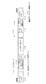
まず、本発明の実施例の追記型光ディスクの記録構造並びにその光ディスクに記録された情報及びデータについて説明する。図1は本発明の実施例である追記型光ディスクの記録構造を示している。尚、図1中の左側が追記型光ディスク100の内周側であり、図1中の右側が光ディスク100の外周側である。
(Example of information recording medium)
First, a recording structure of a write-once optical disc according to an embodiment of the present invention and information and data recorded on the optical disc will be described. FIG. 1 shows a recording structure of a write-once optical disc that is an embodiment of the present invention. Note that the left side in FIG. 1 is the inner peripheral side of the write-once
図1に示すように、追記型光ディスク100の記録面上には、その最内周側にリードインエリア101が存在し、リードインエリア101内には一時的ディフェクト管理エリア104が配置されている。そして、以下その外周に向けて、スペアエリア109、ユーザデータエリア108、スペアエリア110、リードアウトエリア103が配置されており、スペアエリア110内には一時的ディフェクト管理エリア105が配置されている。
As shown in FIG. 1, a lead-in
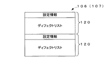
リードインエリア101及びリードアウトエリア103には、夫々、光ディスク100への情報ないしデータの記録・読取を制御及び管理するための制御情報及び管理情報等が記録される。リードインエリア101内には、確定的ディフェクト管理エリア106が設けられている。リードアウトエリア103内にも、確定的ディフェクト管理エリア107が設けられている。確定的ディフェクト管理エリア106及び107には、夫々、ディフェクト管理情報120(図2参照)が記録される。
In the lead-in
本実施例では特に、リードインエリア101に配置される一時的ディフェクト管理エリア104内には、フラグエリア111が設けられている。フラグエリア111には、一時的ディフェクト管理エリア104及び105のいずれのエリアに有効となる最新のディフェクト管理情報120が記録されているか(即ち、一時的ディフェクト管理エリア104及び105のいずれが使用中或いは記録中であるか)を識別する第1識別情報が記録される。更にフラグエリア111には、一時的ディフェクト管理エリア104又は105中におけるいずれの記録領域(或いは、記録位置)に最新のディフェクト管理情報120が記録されているかを識別する第2識別情報が記録される。尚、係るフラグエリア111及び各識別情報の詳細については後に詳述する(図8等参照)。
Particularly in the present embodiment, a flag area 111 is provided in the temporary
尚、本実施例において、フラグエリア111はリードインエリア101内の一時的ディフェクト管理エリア104に設けられているが、これに限らず例えば一時的ディフェクト管理エリア105に設けるように構成してもよいし、本発明における「制御情報記録エリア」の一具体例たるリードインエリア101やリードアウトエリア103に設けるように構成してもよいし、或いはそれ以外のエリアに設けるように構成してもよい。そして、このようなフラグエリア111の位置等については、後述の設定情報121中や或いは例えばリードインエリア101等に記録されている各種情報等により示されるように構成してもよい。
In this embodiment, the flag area 111 is provided in the temporary
ユーザデータエリア108には、画像データ、音声データ、コンテンツデータなどといった記録データが記録される。スペアエリア109及び110は、ユーザデータエリア108内のディフェクトから記録データを退避させるための代替記録領域である。即ち、ユーザデータエリア108にディフェクトが存在するときに、そのディフェクトが存在する場所に記録すべきであった記録データ又はその場所に記録されていた記録データ(以降、このような記録データを適宜“退避データ”と称する)は、スペアエリア109又は110に代替的に記録される。
In the
一時的ディフェクト管理エリア104及び105には、夫々、ディフェクト管理情報120が一時的に記録される。尚、確定的ディフェクト管理エリア106及び107にもディフェクト管理情報120が記録されるが、確定的ディフェクト管理エリア106及び107と一時的ディフェクト管理エリア104及び105との相違については、後述する。
In the temporary
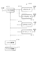
次に、ディフェクト管理情報120について説明する。ディフェクト管理情報120は、記録再生装置200(図13参照)により行われるディフェクト管理に用いられる情報である。記録再生装置200は、光ディスク100に記録データを記録するとき、又は光ディスク100から記録データを再生するときにディフェクト管理を行う。本実施例においてディフェクト管理とは、主に、光ディスク100のユーザデータエリア108上に傷、塵埃又は劣化等のディフェクトが存在するときに、そのディフェクトが存在する場所を避けて記録データを記録すると共に、退避データをスペアエリア109又は110に記録するといったものである。また、ユーザデータエリア108に記録された記録データを再生するときに、ディフェクトの存在する位置を認識し、ディフェクトの存在する位置に本来記録されるべきであった又は記録されていた記録データを、スペアエリア109又は110から読み取るといった処理もディフェクト管理の一環として行われる。このようなディフェクト管理を行うためには、記録再生装置200がユーザデータエリア108内におけるディフェクトの存在位置等を認識する必要がある。ディフェクト管理情報120は、主として記録再生装置200がディフェクトの存在位置等を認識するために用いられる。
Next, the
図2はディフェクト管理情報120の内容を示している。図2に示すように、ディフェクト管理情報120には、設定情報121及びディフェクトリスト122が含まれている。
FIG. 2 shows the contents of the
設定情報121には、図2に示すように、ユーザデータエリア108の開始アドレス、ユーザデータエリア108の終了アドレス、内周側のスペアエリア109のサイズ、外周側のスペアエリア110のサイズ、その他の情報が含まれている。
In the setting information 121, as shown in FIG. 2, the start address of the
図3はディフェクトリスト122の内容を示している。図3に示すように、ディフェクトリスト122には、ユーザデータエリア108内におけるディフェクトが存在する位置を示すアドレス(以下、これを「ディフェクトアドレス」と呼ぶ。)と、退避データのスペアエリア109又は110内における記録位置を示すアドレス(以下、これを「代替記録アドレス」と呼ぶ。)と、その他の情報とが記録されている。ユーザデータエリア108内に複数のディフェクトが存在するときには、それらのディフェクトに対応した複数のディフェクトアドレスと複数の代替記録アドレスがディフェクトリスト122内に記録される。
FIG. 3 shows the contents of the
尚、ディフェクト管理は、光ディスク100のユーザデータエリア108についてだけでなく、光ディスク100の記録面全体について行うことも可能である。
The defect management can be performed not only on the
次に、ディフェクト管理情報120の記録の態様について説明する。光ディスク100の一時的ディフェクト管理エリア104及び105と、確定的ディフェクト管理エリア106及び107は、いずれも、ディフェクト管理情報120を記録するための領域であるが、一時的ディフェクト管理エリア104及び105と、確定的ディフェクト管理エリア106及び107は、配置されている位置が異なり、夫々のサイズが異なり、利用目的も異なる。以下、具体的に両者の違いを説明する。
Next, the recording mode of the
図4は一時的ディフェクト管理エリア104又は105にディフェクト管理情報120が記録された状態の一例を示している。一時的ディフェクト管理エリア104及び105は、光ディスク100がファイナライズされるまでの間に、ディフェクト管理情報120を一時的に記録するための領域である。ディフェクト管理情報120は、ディフェクト管理に必要な情報であり、ディフェクトの存否・位置は個々の光ディスクごとに異なるため、ディフェクト管理情報は個々の光ディスク上に記録して保持しておく必要がある。本実施例では、ファイナライズ前の段階では、ディフェクト管理情報120は光ディスク100の一時的ディフェクト管理エリア104又は105に記録され、保持される。
FIG. 4 shows an example of a state in which the
更に、本実施例では、図4に示すように、ディフェクト管理情報120は、一時的ディフェクト管理エリア104又は105に2回反復的に記録されることが好ましい(尚、図4はディフェクト管理情報120の反復的記録が2度行われた状態を示しているため、合計4個のディフェクト管理情報120が描かれている)。これにより、ディフェクト管理情報120を確実に記録でき、確実に再生することができる。但し、2回記録されなくとも、例えば1回の記録或いは3回以上の記録であっても、ディフェクト管理情報120や退避データを適切に記録し、再生することが可能である。
Furthermore, in the present embodiment, as shown in FIG. 4, the
光ディスク100がファイナライズされるまでの間、ディフェクト管理情報120が数度更新される場合がある。例えば、1度目の記録と2度目の記録(追記)との間に、光ディスク100に汚れが付着したような場合には、2度目の記録時にそのディフェクト(汚れ)が検出され、これに基づいてディフェクトリスト122が更新される。ディフェクトリスト122が更新されると、その更新されたディフェクトリスト122を含むディフェクト管理情報120が一時的ディフェクト管理エリア104又は105に追記される。光ディスク100は追記型の記録媒体であるため、更新されたディフェクト管理情報120を既存のディフェクト管理情報120の上に重ねて記録することはできない。そのため、図4に示すように、更新されたディフェクト管理情報120は、既存のディフェクト管理情報120の後に連続的に記録される。従って、上述した「最新のディフェクト管理情報120」とはこの場合、2度目に追記されたディフェクト管理情報120のことを示す。
Until the
このようなディフェクト管理情報120の反復的かつ並列的な記録を実現するために、一時的ディフェクト管理エリア104及び105は、確定的ディフェクト管理エリア106及び107よりも広い。
In order to realize such repetitive and parallel recording of the
尚、これらの複数の一時的ディフェクト管理エリア104及び105は、連続的に使用されることが好ましい。即ち、例えば一時的ディフェクト管理エリア104に空き容量がなくなった後に、他の一時的ディフェクト管理エリア105を使用することが好ましい。そして、その使用の順番も予め定まっていることが好ましい。この情報は、例えばリードインエリア101等に記録されていてもよいし、設定情報121として記録されていてもよいし、或いはその他のエリアに記録されていてもよい。
The plurality of temporary
又、ディフェクト管理情報120は、図4に示すように一時的ディフェクト管理エリア104又は105に連続的に(シーケンシャルに)記録されることが好ましい。そして、一時的ディフェクト管理エリア104及び105について、ディフェクト管理情報120を記録する順を予め定めておくことが好ましい。但し、ディフェクト管理情報120がシーケンシャルに記録されなくとも、本実施例におけるディフェクト管理を行うことは可能である。
The
そして、本実施例では特に、ディフェクト管理情報120の更新の際に、必要に応じてフラグエリア111の識別情報(即ち、第1識別情報及び第2識別情報の少なくとも一方)も更新される。即ち、例えば、一時的ディフェクト管理エリア104の空き容量がなくなり、それ以後のディフェクト管理情報120が一時的ディフェクト管理エリア105に記録される場合に、フラグエリア111の第1識別情報が更新される。従って、このときの識別情報(具体的には、第1識別情報)は、最新のディフェクト管理情報120が一時的ディフェクト管理エリア105に記録されていることを示す。更に、一時的ディフェクト管理エリア104又は105中における最新のディフェクト管理情報120が記録されている記録領域が変化した場合に、必要に応じてフラグエリア111中の第2識別情報が更新される。これらの識別情報の具体的な構成やその更新等に関しては、後に詳述する(図8等参照)。
In particular, in the present embodiment, when the
一方、図5は確定的ディフェクト管理エリア106又は107内にディフェクト管理情報120が記録された状態の一例を示している。確定的ディフェクト管理エリア106及び107は、光ディスク100がファイナライズされるときに、ディフェクト管理情報120を確定的に記録するための領域である。即ち、ファイナライズ前の段階では、確定的ディフェクト管理エリア106及び107は未記録状態である。ファイナライズされると、確定的ディフェクト管理エリア106及び107にディフェクト管理情報120が記録され、それ以降、その記録状態が継続する。
On the other hand, FIG. 5 shows an example of a state in which the
本実施例では、図5に示すように、ディフェクト管理情報120は、確定的ディフェクト管理エリア106又は107に2回反復的に記録されることが好ましい。これにより、ディフェクト管理情報120を確実に記録でき、確実に再生することができる。但し、2回記録されなくとも、例えば1回の記録或いは3回以上の記録であっても、ディフェクト管理情報120を適切に記録し、再生することが可能である。
In this embodiment, as shown in FIG. 5, the
本実施例の光ディスク100によれば、一時的ディフェクト管理エリア104をスペアエリア109の最内周側(即ち、リードインエリア101と隣接する側)に配置し、一時的ディフェクト管理エリア105をスペアエリア110の最外周側(即ち、リードアウトエリア103と隣接する側)に配置したから、追記型光ディスク100と一般の書換型光ディスクとの間で互換性をとることができる。なぜなら、一般の書換型光ディスクとの互換性を実現するためには、リードインエリア、スペアエリア、ユーザデータエリア、スペアエリア、及びリードアウトエリアが存在すること、これらの領域の順序、配置、サイズ(広さ)等の基本的記録構造を維持する必要があるが、光ディスク100では一時的ディフェクト管理エリア104及び105を設けたにもかかわらず、かかる基本的記録構造を維持しているからである。即ち、仮に一時的ディフェクト管理エリア104をリードインエリア101内に配置するとすれば、上述したように一時的ディフェクト管理エリア104は比較的広いので、リードインエリア101のサイズを拡張せざるを得なくなるという不都合が生じる。しかし、本実施例では、一時的ディフェクト管理エリア104をリードインエリア101の外に配置したので、かかる不都合は生じない。また、仮に一時的ディフェクト管理エリア104をユーザデータエリア108内に設けるとすれば、制御情報の性質を有するディフェクト管理情報120が、記録データを記録すべき領域であるユーザデータエリア108に入り込み、制御情報と記録データという性質の異なる情報がユーザデータエリア108内に混在するといった不都合が生じる。本実施例では、一時的ディフェクト管理エリア104をユーザデータエリア108の外に配置したので、かかる不都合は生じない。ディフェクト管理エリア105についても同様である。
According to the
尚、ユーザデータエリア108の開始アドレス及び終了アドレス、スペアエリア109の開始アドレス並びにスペアエリア110の開始アドレス(或いは、ユーザデータエリア108やスペアエリア109及び110のサイズ等)は、ディフェクト管理情報120の設定情報121に含まれている(図2参照)。そして、この設定情報121は、記録再生装置200により設定することができる。即ち、ユーザデータエリア108の開始アドレス及び終了アドレス、スペアエリア109のサイズ並びに110のサイズは、これを設定情報121として明示しておけば、変更することが許容されており、変更しても、一般の書換型記録媒体との互換性を維持することができる。従って、ユーザデータエリア108の開始アドレスを後ろ(外周側)にずらせば、リードインエリア101とユーザデータエリア108との間にスペースを確保することができ、そのスペースに一時的ディフェクト管理エリア104を配置することができる。更に、ユーザデータエリア108の開始アドレスの設定の仕方によっては、比較的広い(大きなサイズの)一時的ディフェクト管理エリア104を確保することができる。一時的ディフェクト管理エリア105についても同様である。
The start address and end address of the
また、本実施例の光ディスク100によれば、リードインエリア101内及びリードアウトエリア103内に夫々確定的ディフェクト管理エリア106及び107を配置したから、追記型光ディスク100と一般の書換型光ディスクとの間で互換性をとることができる。即ち、一般の書換型光ディスクは、そのリードインエリア内及びリードアウトエリア内に夫々ディフェクト管理情報を記録すべき領域が配置されている。そして、光ディスク100も、そのリードインエリア101内及びリードアウトエリア103内に確定的ディフェクト管理エリア106及び107が配置されている。かかる点において、両者の記録構造は一致している。従って、追記型光ディスク100と一般の書換型光ディスクとの間で再生時の互換性をとることができる。
Further, according to the
尚、上述した実施例では、本発明の情報記録媒体を一層の光ディスクに適用した場合を例に挙げたが、本発明はこれに限らず、2層以上の光ディスクにも適用することができる。図6及び図7は夫々、本発明の情報記録媒体を2層光ディスクに適用した場合の例を示している。図6中の2層光ディスク150aの第1層(図6中の上段)には、光ディスク100と同様に、その最内周側にリードインエリア151が存在し、リードインエリア151内には一時的ディフェクト管理エリア154が配置されている。そして、以下その外周に向けて、スペアエリア159、ユーザデータエリア158、スペアエリア160、リードアウトエリア153が配置されており、スペアエリア160内には、一時的ディフェクト管理エリア155が配置されている。そして、リードインエリア151に配置される一時的ディフェクト管理エリア154内にはフラグエリア161が設けられている。第2層にも、光ディスク100と同様に、その最内周側にリードインエリア171が存在し、リードインエリア171内には一時的ディフェクト管理エリア174が配置されている。そして、以下その外周に向けて、スペアエリア179、ユーザデータエリア178、スペアエリア180、リードアウトエリア173が配置されており、スペアエリア179内には一時的ディフェクト管理エリア175bが、またスペアエリア180内には一時的ディフェクト管理エリア175aが配置されている。
In the above-described embodiments, the case where the information recording medium of the present invention is applied to a single optical disk has been described as an example. However, the present invention is not limited to this, and can be applied to an optical disk having two or more layers. 6 and 7 show examples in which the information recording medium of the present invention is applied to a two-layer optical disc. A lead-in
尚、図6における2層以上の光ディスクに係る説明は、第1層と第2層の記録方向が同一のパラレルトラックパスの例を示すが、図7に示すように、第1層と第2層の記録方向が逆方向となるオポジットトラックパスの形態を採ってもよい。図7に示すパラレルトラックパスの光ディスク150bであっても、図6に示すオポジットトラックパスの光ディスク150aと概ね同様のデータ構造を有している。具体的には、第1層については、その最内周側にリードインエリア151が存在し、リードインエリア151内には一時的ディフェクト管理エリア154が配置されている。そして、以下その外周に向けて、スペアエリア159、ユーザデータエリア158、スペアエリア160、ミドルエリア162が配置されており、スペアエリア160内には一時的ディフェクト管理エリア155が配置されている。第2層については、その最内周側にリードアウトエリア173が存在し、リードアウトエリア173内には一時的ディフェクト管理エリア175aが配置されている。そして、以下その外周に向けて、スペアエリア180、ユーザデータエリア178、スペアエリア179、ミドルエリア182が配置されており、スペアエリア180内には一時的ディフェクト管理エリア175bが、またスペアエリア179内には一時的ディフェクト管理エリア174が配置されている。
The description relating to the optical disk having two or more layers in FIG. 6 shows an example of parallel track paths in which the recording directions of the first layer and the second layer are the same. However, as shown in FIG. An opposite track path may be used in which the recording direction of the layers is reversed. The parallel track path optical disc 150b shown in FIG. 7 has a data structure substantially similar to that of the opposite track path
続いて、図8及び図9を参照して、フラグエリアのデータ構造についてより詳細に説明する。ここに、図8は、図1に示した1層光ディスク100におけるフラグエリア111のより詳細なデータ構造、及び図7に示した2層光ディスク150bにおけるフラグエリア161のより詳細なデータ構造を示す図であり、図9は、リードインエリア151及び一時的ディフェクト管理エリア154の夫々との関連を示しながらフラグエリア161のデータ構造をより詳細に示すデータ構造図である。
Next, the data structure of the flag area will be described in more detail with reference to FIGS. 8 shows a more detailed data structure of the flag area 111 in the single-layer
図8(a)に示すように、フラグエリア111内には、3つのフラグ単位領域(113a、114a、114b)が存在している。この3つのフラグ単位領域の夫々の大きさは、光ディスク100へのデータの記録単位である(或いは、最小記録領域である)ECCクラスタの領域の大きさに相当している。但し、ECCクラスタの領域の大きさに限らずとも、任意の領域の大きさを、当該フラグエリア111中のフラグ単位領域の大きさとしてもよい。そして、これら3つのフラグ単位領域の夫々の大きさは、いずれも同一であってもよいし、或いは異なっていてもよい。
As shown in FIG. 8A, in the flag area 111, there are three flag unit areas (113a, 114a, 114b). The size of each of the three flag unit areas corresponds to the size of an ECC cluster area that is a data recording unit (or a minimum recording area) on the
そして、特に、フラグ単位領域113aにおけるデータの記録状態により第1識別情報が記録され、フラグ単位領域114a及び114bの夫々におけるデータの記録状態により第2識別情報が記録される。言い換えれば、フラグ単位領域113aが記録済状態であるか又は未記録状態であるかに応じて、フラグ単位領域113a全体で第1識別情報に相当する情報が記録され、フラグ単位領域114a及び114bの夫々が記録済状態であるか又は未記録状態であるかに応じて、フラグ単位領域114a及び114b全体で第2識別情報に相当する情報が記録される。 In particular, the first identification information is recorded according to the data recording state in the flag unit area 113a, and the second identification information is recorded according to the data recording state in each of the flag unit areas 114a and 114b. In other words, information corresponding to the first identification information is recorded in the entire flag unit area 113a depending on whether the flag unit area 113a is in a recorded state or in an unrecorded state, and the flag unit areas 114a and 114b Information corresponding to the second identification information is recorded in the entire flag unit areas 114a and 114b depending on whether each is in a recorded state or an unrecorded state.
具体的には、図1に示す光ディスク100は、2つの一時的ディフェクト管理エリア104及び105を有しているため、第1識別情報を記録するために、図8(a)に示すように少なくとも一つのフラグ単位領域があれば足りる。即ち、フラグ単位領域113aが未記録状態であれば、最新のディフェクト管理情報120が一時的ディフェクト管理エリア104に記録されており、一方フラグ単位領域113aが記録済状態であれば、最新のディフェクト管理情報120が一時的ディフェクト管理エリア105に記録されていることを示すように第1識別情報を記録してもよい。
Specifically, since the
また、一時的ディフェクト管理エリア104又は105中における最新のディフェクト管理情報120の記録領域を識別するための第2識別情報は、2つのフラグ単位領域114a及び114bから構成されている。このため、例えば一つの一時的ディフェクト管理エリアを3つの分割エリアに分割すると、この3つの分割エリアのいずれに最新のディフェクト管理情報120が記録されているかを、第2識別情報に基づいて識別することができる。
The second identification information for identifying the recording area of the latest
更に、図8(b)に示すように、フラグエリア161内には、9つのフラグ単位領域(163a、163b、163c、163d、164a、164b、164c、164d、164e、)が存在している。そして、図8(a)に示す場合と同様に、フラグ単位領域163aから163dにおけるデータの記録状態により第1識別情報が記録され、フラグ単位領域164aから164eの夫々におけるデータの記録状態により第2識別情報が記録される。
Further, as shown in FIG. 8B, there are nine flag unit areas (163a, 163b, 163c, 163d, 164a, 164b, 164c, 164d, 164e) in the
具体的には、図7に示す光ディスク150bは、5つの一時的ディフェクト管理エリア154、155、174、175a及び175bを有しているため、第1識別情報を記録するために、図8(b)に示すように少なくとも4つのフラグ単位領域があれば足りる。また、一時的ディフェクト管理エリア154、155、174、175a又は175bにおける最新のディフェクト管理情報120の記録位置を識別するための第2識別情報は、5つのフラグ単位領域164aから164eから構成されている。このため、例えば一つの一時的ディフェクト管理エリアを6つの分割エリアに分割すると、この6つの分割エリアのいずれに最新のディフェクト管理情報120が記録されているかを、第2識別情報に基づいて識別することができる。
Specifically, since the optical disc 150b shown in FIG. 7 has five temporary
以上まとめると、第1識別情報を記録するためのフラグ単位領域の数は、当該光ディスクが備える一時的ディフェクト管理エリアの数より1だけ小さい数であることが好ましい。即ち、光ディスクが備える一時的ディフェクト管理エリアがn(但し、nは2以上の整数)個存在していれば、第1識別情報を記録するためのフラグ単位領域の数はn−1個であることが好ましい。例えば図1に示す光ディスク100であれば、一時的ディフェクト管理エリアは2つ存在しているため、フラグ単位領域は一つでよい。又、例えば図6に示す光ディスク150a及び図7に示す光ディスク150bであれば、一時的ディフェクト管理エリアは5つ存在しているため、フラグ単位領域は、図8(b)に示すように4つであることが好ましい。
In summary, the number of flag unit areas for recording the first identification information is preferably one less than the number of temporary defect management areas included in the optical disc. That is, if there are n (where n is an integer of 2 or more) temporary defect management areas included in the optical disc, the number of flag unit areas for recording the first identification information is n-1. It is preferable. For example, in the case of the
また、第2識別情報を記録するためのフラグ単位領域の数は、一つの一時的ディフェクト管理エリア又は複数の一時的ディフェクト管理エリアの組を仮想的に複数の分割エリアに分割した際の、当該分割エリアの数より1だけ小さい数であることが好ましい。即ち、一又は複数の一時的ディフェクト管理エリアを仮想的にm(但し、mは2以上の整数)個の分割エリアに分割すれば、第2識別情報を記録するためのフラグ単位領域の数はm−1個であることが好ましい。 Further, the number of flag unit areas for recording the second identification information is the number of the temporary defect management area or the combination of a plurality of temporary defect management areas virtually divided into a plurality of divided areas. The number is preferably one smaller than the number of divided areas. That is, if one or a plurality of temporary defect management areas are virtually divided into m (where m is an integer of 2 or more) divided areas, the number of flag unit areas for recording the second identification information is as follows. It is preferable that it is m-1.
尚、このフラグエリア111(或いは、161)における各フラグ単位領域の記録状態と第1及び第2識別情報との具体的な関係については後に詳述する(図10等参照)。 A specific relationship between the recording state of each flag unit area in the flag area 111 (or 161) and the first and second identification information will be described in detail later (see FIG. 10 and the like).
尚、本実施例における「記録済状態」とは、当該フラグ単位領域中においてピット(或いは、マーク等)が形成されている状態を示す趣旨であり、係るピット等が所定の記録データを示していてもよいし、示していなくともよい。例えば、フラグ単位領域中に映像データ等のバックアップデータを記録するように構成してもよいし、映像データ等自体を記録するように構成してもよいし、それ以外の他の用途(例えば、記録制御や再生制御等)に用いられる各種データを記録するように構成してもよいし、或いは何らの用途にも用いない例えば“00h”データ等を記録するように構成してもよい。一方、本実施例における「未記録状態」とは、当該フラグ単位領域中においてピット等が形成されておらず、ミラー状の平面に相当する記録層を有している状態を示す趣旨である。 The “recorded state” in the present embodiment is intended to indicate a state in which pits (or marks or the like) are formed in the flag unit area, and the pits or the like indicate predetermined recording data. It may or may not be shown. For example, it may be configured to record backup data such as video data in the flag unit area, may be configured to record video data or the like, or other uses (for example, for example, Various data used for recording control, reproduction control, etc.) may be recorded, or for example, “00h” data that is not used for any purpose may be recorded. On the other hand, the “unrecorded state” in the present embodiment is intended to indicate a state in which no pit or the like is formed in the flag unit area and a recording layer corresponding to a mirror-like plane is provided.
図9に示すように、フラグエリア161は、リードインエリア151中の一時的ディフェクト管理エリア154中に設けられる。特に、一時的ディフェクト管理エリア154の先頭部分(即ち、最内周側或いはアドレス値がより小さい側)にフラグエリア161が設けられることが好ましい。例えば、図9に示すように、2048クラスタ(即ち、ECCクラスタ)からなる一時的ディフェクト管理エリア154のうち先頭9クラスタをフラグエリア161として割り当ててもよい。もちろん、それ以外のエリアをフラグエリア161用に、例えばリザーブドエリア(Reserved Area)として確保してもよいし、また一時的ディフェクト管理エリア154の終端部分(即ち、最外周側或いはアドレス値がより大きい側)に記録してもよいし、それ以外の部分に記録してもよい。
As shown in FIG. 9, the
このように、リードインエリア154中の一時的ディフェクト管理エリア154の先頭部分にフラグエリア161を設けることで、後述の記録再生装置に光ディスク150b等がローディングされた後、比較的初期の動作段階で当該フラグエリア161にアクセスすることができる。また、光ディスク150bのローディング後の光ピックアップの移動を最小限に抑えることも可能となる。従って、より効率的にフラグエリア161にアクセスすることができるという大きな利点を有している。
As described above, by providing the
続いて、図10から図13を参照して、図8(b)に示したフラグエリア161に係る記録状態の具体的な一の例と、その際の光ディスク150bにおける最新のディフェクト管理情報120の記録領域との関係について説明する。ここに、図10は、最新のディフェクト管理情報120が記録されている一時的ディフェクト管理エリアに応じて変化するフラグ単位領域163aから163dの記録態様の一具体例を概念的に示す模式図であり、図11及び図12は、フラグ単位領域164aから164eの記録態様に対応する一時的ディフェクト管理エリアの分割の態様を示すデータ構造図であり、図13は、最新のディフェクト管理情報120が記録される記録領域に応じて変化するフラグ単位領域164aから164eの記録態様の一具体例を概念的に示す模式図である。
Subsequently, referring to FIGS. 10 to 13, a specific example of the recording state related to the
先ず、第1識別情報の記録の態様について説明する。 First, a mode of recording the first identification information will be described.
図10(a)に示すように、フラグ単位領域163a、163b、163c及び163dのいずれもが未記録の状態にある場合には、例えば一時的ディフェクト管理エリア154に最新のディフェクト管理情報120が記録されていることを示している。即ち、最新のディフェクト管理情報120が一時的ディフェクト管理エリア154に記録されていることを示している。
As shown in FIG. 10A, when all of the
図10(b)に示すように、フラグ単位領域163aが記録済の状態にあり、フラグ単位領域163b、163c及び163dが未記録の状態にある場合には、例えば一時的ディフェクト管理エリア155に最新のディフェクト管理情報120が記録されていることを示している。
As shown in FIG. 10B, when the
図10(c)に示すように、フラグ単位領域163a及び163bが記録済の状態にあり、フラグ単位領域163c及び163dが未記録の状態にある場合には、例えば一時的ディフェクト管理エリア174に最新のディフェクト管理情報120が記録されていることを示している。
As shown in FIG. 10C, when the
図10(d)に示すように、フラグ単位領域163a、163b及び163cが記録済の状態にあり、フラグ単位領域163dが未記録の状態にある場合には、例えば一時的ディフェクト管理エリア175aに最新のディフェクト管理情報120が記録されていることを示している。
As shown in FIG. 10D, when the
図10(e)に示すように、フラグ単位領域163a、163b、163c及び163dのいずれもが記録済の状態にある場合には、例えば一時的ディフェクト管理エリア175bに最新のディフェクト管理情報120が記録されていることを示している。
As shown in FIG. 10E, when all of the
従って、例えば後述の記録再生装置をして光ディスク150bを再生すれば、最新のディフェクト管理情報120が記録されている一時的ディフェクト管理エリアを比較的容易に検索することが可能となる。従って、ディフェクト管理情報120の検索に要する時間を低減でき、その結果再生動作の高速化を図ることが可能となる。
Therefore, for example, when the optical disc 150b is reproduced by using a recording / reproducing apparatus described later, it is possible to relatively easily search the temporary defect management area in which the latest
尚、例えば光ディスク150bに一時的ディフェクト管理エリア155及び174の夫々が存在しない場合(即ち、一時的ディフェクト管理エリアが3つしか存在しない場合)等には、それに合わせて第1識別情報を記録するためのフラグ単位領域を小さくして(即ち、クラスタ数を減少させて)もよい。或いは、図10に示すフラグ単位領域の記録態様のように、フラグ単位領域を小さくすることなく第1識別情報を記録してもよい。即ち、最新のディフェクト管理情報120が記録されている一時的ディフェクト管理エリアの遷移に応じて、図10(a)、図10(b)及び図10(e)に示すようにフラグ単位領域の記録パターンを変化させる(即ち、図10(c)及び図10(d)に示す記録パターンを省略する)ことで、最新のディフェクト管理情報120が記録されている一時的ディフェクト管理エリアを効率的に検索することができる。
For example, when each of the temporary
続いて、第2識別情報について説明する。第2識別情報を説明する前提として、上述した一時的ディフェクトエリアの分割エリアについて説明する。尚、図11及び図12では、説明の便宜上、図7において上述したデータ構造のうち一部の構造(即ち、エリア)を抜粋して説明を進める。 Next, the second identification information will be described. As a premise for explaining the second identification information, the division area of the temporary defect area described above will be explained. 11 and 12, for convenience of explanation, a part of the data structure (that is, area) is extracted from the data structure described above in FIG.
図11(a)に示すように、例えばスペアエリア160及び179のデータサイズが拡張されることに起因して、一時的ディフェクト管理エリア155及び174の夫々が、比較的大きな(例えば、数十GBの)データサイズを有している場合には、図11(b)に示すように、一時的ディフェクト管理エリア155及び174を組にしたエリアを対象として、複数の(図11では6つの)分割エリアに分割するように構成してもよい。即ち、第1から第6の6つの分割エリアに分割するように構成してもよい。
As shown in FIG. 11A, the temporary
この一時的ディフェクト管理エリアの分割は、所定サイズを有する固定長の分割エリアとして分割してもよい。例えば、所定サイズを4GBとすれば、4GBのデータサイズを有する分割エリア毎に分割してもよい。或いは一時的ディフェクト管理エリアを所定数の分割エリアができるように分割してもよい。即ち、一時的ディフェクト管理エリアの分割毎にデータサイズが異なる分割エリアに(いわば、可変長の分割エリアに)分割されるように分割してもよい。例えば、20GBのデータサイズを有する一時的ディフェクト管理エリアを例えば2つの分割エリア(即ち、10GBのデータサイズを夫々有する2つの分割エリア)に、4つの分割エリア(即ち、5GBのデータサイズを夫々有する4つの分割エリア)に、5つの分割エリア(即ち、2GBのデータサイズを夫々有する5つの分割エリア)等に分割してもよい。 The temporary defect management area may be divided as a fixed-length divided area having a predetermined size. For example, if the predetermined size is 4 GB, it may be divided for each divided area having a data size of 4 GB. Alternatively, the temporary defect management area may be divided so that a predetermined number of divided areas are formed. In other words, the temporary defect management area may be divided so as to be divided into divided areas having different data sizes (so-called variable-length divided areas). For example, a temporary defect management area having a data size of 20 GB, for example, has two divided areas (that is, two divided areas each having a data size of 10 GB), and has four divided areas (that is, data sizes of 5 GB, respectively) You may divide into four division areas), for example, into five division areas (that is, five division areas each having a data size of 2 GB).
尚、最新のディフェクト管理情報120が記録されている記録領域をより狭い範囲において特定したい場合には、分割エリアのサイズを相対的に小さくすることが好ましい。他方、フラグエリア161のデータサイズをより小さくしたい場合には、分割エリアのサイズを相対的に大きくすることが好ましい。
In order to specify the recording area in which the latest
或いは、図12(a)に示すように、スペアエリア180のデータサイズが拡張されることに起因して、一時的ディフェクト管理エリア175bが、比較的大きなデータサイズを有している場合には、図12(b)に示すように、一時的ディフェクト管理エリア175bを複数の(図12(b)では6つの)分割エリアに分割するように構成してもよい。
Alternatively, as shown in FIG. 12A, when the temporary
もちろん実際にこのように分割して一時的ディフェクト管理エリアを扱う必要はなく、第2識別情報を記録するために、仮想的に一時的ディフェクト管理エリアを分割すれば足りる。更に、図11及び図12において示した分割の例に限らず、他の分割の態様にて一時的ディフェクト管理エリアを分割するように構成してもよい。 Of course, it is not necessary to actually divide the temporary defect management area in this way, and it is sufficient to virtually divide the temporary defect management area in order to record the second identification information. Furthermore, the present invention is not limited to the example of division shown in FIGS. 11 and 12, and the temporary defect management area may be divided in other division modes.
図11及び図12の夫々に示した6つの分割エリアに対応して、第2識別情報を記録すると、例えば図13に示すような記録の態様を一の具体例としてあげることができる。 When the second identification information is recorded corresponding to the six divided areas shown in FIGS. 11 and 12, for example, a recording mode as shown in FIG. 13 can be given as one specific example.
図13(a)に示すように、フラグ単位領域164a、164b、164c、164d及び163eのいずれもが未記録の状態にある場合には、例えば第1の分割エリアに最新のディフェクト管理情報120が記録されていることを示している。言い換えれば、一時的ディフェクト管理エリアのうち第1の分割エリアに相当する記録領域を使用して、現時点でディフェクト管理情報を記録していることを示している。
As shown in FIG. 13A, when all of the flag unit areas 164a, 164b, 164c, 164d, and 163e are in an unrecorded state, for example, the latest
図13(b)に示すように、フラグ単位領域164aが記録済の状態にあり、フラグ単位領域164b、164c、164d及び163eが未記録の状態にある場合には、例えば第2の分割エリアに最新のディフェクト管理情報120が記録されていることを示している。
As shown in FIG. 13B, when the flag unit area 164a is in a recorded state and the flag unit areas 164b, 164c, 164d, and 163e are in an unrecorded state, for example, in the second divided area. It shows that the latest
図13(c)に示すように、フラグ単位領域164a及び164bが記録済の状態にあり、フラグ単位領域164c、164d及び164eが未記録の状態にある場合には、例えば第3の分割エリアに最新のディフェクト管理情報120が記録されていることを示している。
As shown in FIG. 13C, when the flag unit areas 164a and 164b are in a recorded state and the
図13(d)に示すように、フラグ単位領域164a、164b及び164cが記録済の状態にあり、フラグ単位領域164d及び164eが未記録の状態にある場合には、例えば第4の分割エリアに最新のディフェクト管理情報120が記録されていることを示している。
As shown in FIG. 13D, when the flag unit areas 164a, 164b, and 164c are in a recorded state and the
図13(e)に示すように、フラグ単位領域164a、164b、164c及び164dが記録済の状態にあり、フラグ単位領域164eが未記録の状態にある場合には、例えば第5の分割エリアに最新のディフェクト管理情報120が記録されていることを示している。
As shown in FIG. 13E, when the flag unit areas 164a, 164b, 164c and 164d are in a recorded state and the
図13(f)に示すように、フラグ単位領域164a、164b、164c、164d及び164eのいずれもが記録済の状態にある場合には、例えば第6の分割エリアに最新のディフェクト管理情報120が記録されていることを示している。
As shown in FIG. 13F, when all of the
従って、例えば後述の記録再生装置をして光ディスク150bを再生すれば、一時的ディフェクト管理エリア中における最新のディフェクト管理情報120が記録されている記録領域を比較的容易に検索することが可能となる。特に、一時的ディフェクト管理エリアが比較的大きなデータサイズ(例えば、数十GB等のデータサイズ)を有している場合には、第1識別情報により最新のディフェクト管理情報120が記録されている一時的ディフェクト管理情報を検索することができても、今度はその一時的ディフェクト管理エリア内において最新のディフェクト管理情報120を検索するのに時間を要する。しかるに、本実施例では、第2識別情報に基づいて、最新のディフェクト管理情報120が一時的ディフェクト管理エリアのいずれの記録領域に記録されているかを比較的容易に識別することができる。例えば、最新のディフェクト管理情報120が、一時的ディフェクト管理エリアの先頭付近に記録されていたり、真ん中付近に記録されていたり、或いは終端付近に記録されていることを識別することができる。具体的には、例えば一時的ディフェクト管理エリアの先頭部分から最新のディフェクト管理情報120を検索することに代えて、例えば第3の分割エリアの先頭部分から検索することができる。従って、比較的大きなデータサイズを有する一時的ディフェクト管理エリアであっても、第2識別情報を参照することで、比較的小さなデータサイズ(例えば、数GBや数百MB等のデータサイズ)のエリアから検索すれば足りる。その結果、より効率的に最新のディフェクト管理情報120を検索することが可能となる。
Therefore, for example, when the optical disc 150b is reproduced by using a recording / reproducing apparatus described later, it is possible to relatively easily search the recording area in which the latest
加えて、本実施例では特に、第1識別情報と第2識別情報とが対になって、いわば一つの識別情報として記録されているため、一度これらの識別情報にアクセスすれば、その後即座に最新のディフェクト管理情報120(或いは、該最新のディフェクト管理情報120が記録される近傍領域)にアクセスすることができる。即ち、最新のディフェクト管理情報120へのアクセスに要する時間を極力短くし、より効率的なアクセスを実現することができるという大きな利点を有している。
In addition, in the present embodiment, in particular, the first identification information and the second identification information are paired and recorded as one identification information, so that once these identification information is accessed, immediately thereafter It is possible to access the latest defect management information 120 (or a neighboring area where the latest
従って、第1及び第2識別情報を利用することで、最新のディフェクト管理情報120の検索に要する時間を低減でき、その結果再生動作等の高速化を図ることが可能となる。
Therefore, by using the first and second identification information, the time required for searching for the latest
尚、上述した実施例では、比較的大きいデータサイズを有する一時的ディフェクト管理エリアを複数の分割エリアに分割することで、当該分割した一時的ディフェクト管理エリアに対応する第2識別情報を記録するように構成しているが、一時的ディフェクトエリアのデータサイズの大小に係わらず、夫々の一時的ディフェクト管理エリアに対応する第2識別情報を記録するように構成してもよい。例えば、図6及び図7に示す光ディスク150a及び150bは、5つの一時的ディフェクト管理エリアを有しているため、夫々の一時的ディフェクト管理エリアに対応して、5つの第2識別情報を記録するように構成してもよい。
In the above-described embodiment, the second defect information corresponding to the divided temporary defect management area is recorded by dividing the temporary defect management area having a relatively large data size into a plurality of divided areas. However, the second identification information corresponding to each temporary defect management area may be recorded regardless of the data size of the temporary defect area. For example, since the
又、光ディスク150b等が追記型であっても、一時的ディフェクト管理エリアの個数に応じて、また一時的ディフェクトエリアを仮想的に分割する際の分割数に応じて当初から割り当てられたフラグエリア161内における未記録状態にあるフラグ単位領域を、何らかの情報の書き込みによって記録済状態に変化させれば、当該フラグエリア161内における記録済状態と未記録状態との組合せのパターンとして識別情報を書き込むことが可能となる。そして、このようにフラグ単位領域を記録済状態とすることで、改めて識別情報を記録せずとも、記録パターンとして識別情報を適切に記録することができる。
Further, even if the optical disk 150b or the like is a write-once type, the
但し、フラグ単位領域の記録状態と該記録状態が示す最新のディフェクト管理情報120が記録されている一時的ディフェクト管理エリア並びに当該一時的ディフェクト管理エリア中における最新のディフェクト管理情報120の記録領域との対応付けは、上述した具体例に示したものに限らず、最新のディフェクト管理情報120が記録されている一時的ディフェクト管理エリア並びに当該一時的ディフェクト管理エリア中における最新のディフェクト管理情報120の記録領域を識別可能であれば任意の記録状態であってもよい。
However, the recording state of the flag unit area, the temporary defect management area in which the latest
尚、図10から図13では図7に示す2層光ディスク150bを用いて説明したが、図1に示す1層の光ディスク100、或いはそれ以外の光ディスク(例えば、図6に示す光ディスク150a)や各種記録媒体であっても2以上の一時的ディフェクト管理エリアを備えている記録媒体であれば、本実施例に係る光ディスクと同様の効果を得ることが可能である。
10 to 13 have been described using the two-layer optical disk 150b shown in FIG. 7, but the single-layer
尚、上述した実施例では、追記型の光ディスクについて説明をしたが、もちろん書換型の光ディスクであっても、上述の構成を採ることで、相応に上述した各種利益を享受することは可能である。 In the above-described embodiment, the write-once type optical disc has been described. Of course, even with a rewritable optical disc, it is possible to enjoy the above-described various benefits by adopting the above configuration. .
(記録再生装置の実施例)
次に、本発明の実施例である記録再生装置の構成について説明する。図14は本発明の実施例である記録再生装置200を示している。記録再生装置200は、光ディスク100に記録データを記録する機能と、光ディスク100に記録された記録データを再生する機能とを備えている。
(Example of recording / reproducing apparatus)
Next, the configuration of the recording / reproducing apparatus according to the embodiment of the present invention will be described. FIG. 14 shows a recording / reproducing
記録再生装置200は、ディスクドライブ300と、バックエンド400とを備えている。
The recording / reproducing
図15はディスクドライブ300の内部構成を示している。ディスクドライブ300は、光ディスク100に情報を記録すると共に、光ディスク100に記録された情報を読み取る装置である。
FIG. 15 shows the internal configuration of the
ディスクドライブ300は、図15に示すように、スピンドルモータ351、光ピックアップ352、RFアンプ353及びサーボ回路354を備えている。
As shown in FIG. 15, the
スピンドルモータ351は光ディスク100を回転させるモータである。
The spindle motor 351 is a motor that rotates the
光ピックアップ352は、光ディスク100の記録面に対して光ビームを照射することによって記録データ等を記録面上に記録すると共に、光ビームの反射光を受け取ることによって記録面上に記録された記録データ等を読み取る装置である。光ピックアップ352は、光ビームの反射光に対応するRF信号を出力する。
The optical pickup 352 records recording data or the like on the recording surface by irradiating the recording surface of the
RFアンプ353は、光ピックアップ352から出力されたRF信号を増幅して、そのRF信号を変調復調部355に出力する。更に、RFアンプ353は、RF信号から、ウォブル周波数信号WF、トラックエラー信号TE及びフォーカスエラー信号FEを作り出し、これらを出力する。
The
サーボ回路354は、トラックエラー信号TE、フォーカスエラー信号FEその他のサーボ制御信号に基づいて光ピックアップ352及びスピンドルモータ351の駆動を制御するサーボ制御回路である。
The
更に、ディスクドライブ300は、図15に示すように、変調復調部355、バッファ356、インターフェース357及び光ビーム駆動部358を備えている。
Further, as shown in FIG. 15, the
変調復調部355は、読取時において記録データに対してエラー訂正を行う機能と、記録時において記録データにエラー訂正符号を付加してこれを変調する機能とを備えた回路である。具体的には、変調復調部355は、読取時においては、RFアンプ353から出力されるRF信号を復調し、これに対してエラー訂正を行った後、これをバッファ356に出力する。更に、変調復調部355は、復調されたRF信号に対してエラー訂正を行った結果、エラー訂正が不能であるか、又はエラー訂正された符号の数がある一定の基準値を超えたときには、その旨を示すエラー信号を生成し、これをディフェクト検出部359に出力する。また、変調復調部355は、記録時においては、バッファ356から出力される記録データにエラー訂正符号を付加した後、これを、光ディスク100の光学的特性等に適合する符号となるように変調し、変調された記録データを光ビーム駆動部358に出力する。
The modulation / demodulation unit 355 is a circuit having a function of performing error correction on the recording data at the time of reading and a function of adding an error correction code to the recording data at the time of recording and modulating it. Specifically, at the time of reading, the modulation / demodulation unit 355 demodulates the RF signal output from the
バッファ356は、記録データを一時的に蓄える記憶回路である。 The buffer 356 is a storage circuit that temporarily stores recording data.
インターフェース357は、ディスクドライブ300とバックエンド400との間の記録データ等の入出力制御ないし通信制御を行う回路である。具体的には、インターフェース357は、再生時においては、バックエンド400からの要求命令に応じて、バッファ356から出力される記録データ(即ち光ディスク100から読み取られた記録データ)をバックエンド400へ出力する。また、インターフェース357は、記録時においては、バックエンド400からディスクドライブ300に入力される記録データを受け取り、これをバッファ356に出力する。更に、インターフェース357は、バックエンド400からの要求命令に応じて、ディフェクト管理情報作成部360に保持されているディフェクトリストの全部又は一部をバックエンド400に出力する。
The interface 357 is a circuit that performs input / output control or communication control of recording data and the like between the
光ビーム駆動部358は、記録時において、変調復調部355から出力された記録データに対応する光ビーム駆動信号を生成し、これを光ピックアップ352に出力する。光ピックアップ352は、光ビーム駆動信号に基づいて光ビームを変調し、光ディスク100の記録面に照射する。これにより、記録データ等が記録面上に記録される。
The light beam drive unit 358 generates a light beam drive signal corresponding to the recording data output from the modulation / demodulation unit 355 during recording, and outputs this to the optical pickup 352. The optical pickup 352 modulates the light beam based on the light beam drive signal and irradiates the recording surface of the
更に、ディスクドライブ300は、図15に示すように、ディフェクト検出部359及びディフェクト管理情報作成部360を備えている。
Further, as shown in FIG. 15, the
ディフェクト検出部359は、光ディスク100のディフェクトを検出する回路である。そして、ディフェクト検出部359は、ディフェクトの存否を示すディフェクト検出信号を生成し、これを出力する。ディフェクト検出部359は、情報の読取時(ベリファイ時又は再生時)における記録データのエラー訂正の結果に基づいて、ディフェクト検出を行う。上述したように、変調復調部355は、復調されたRF信号に対してエラー訂正を行った結果、エラー訂正が不能であるか、又はエラー訂正された符号の数がある一定の基準値を超えたときには、その旨を実質的に示すエラー信号を生成し、これをディフェクト検出部359に出力する。ディフェクト検出部359は、このエラー信号を受け取ったときに、ディフェクトが存在していることを示すディフェクト検出信号を出力する。
The
ディフェクト管理情報作成部360は、ディフェクト検出部359から出力されたディフェクト検出信号に基づいて、ディフェクト管理情報120を作成し、又は更新する回路である。ディフェクト管理情報120は、ディフェクト管理情報作成部360内に設けられた記憶回路に書換可能な状態で記憶される。更に、ディフェクト管理情報作成部360は、バックエンド400からの要求命令に応じて、ディフェクト管理情報120をインタ−フェース357を介してバックエンド400に出力する。
The defect management
更に、図15に示すように、ディスクドライブ300はCPU361を有している。CPU361は、ディスクドライブ300の全体的な制御及び上述したディスクドライブ300内の各要素間の情報のやり取りを制御する。更に、CPU361は、記録データ及びディフェクト管理情報120の記録動作及び読取動作を制御する。更に、CPU361は、バックエンド400から送られる制御命令ないし要求命令に応じて、ディスクドライブ300とバックエンド400との間のデータのやり取りを制御する。
Further, as shown in FIG. 15, the
次に、図16はバックエンド400の内部構成の例を示している。バックエンド400は、ディスクドライブ300によって光ディスク100から読み取られた記録データに対して再生処理を行うと共に、光ディスク100に記録する目的で外部から供給された記録データを受け取り、これをエンコードしてディスクドライブ300に送り出す装置である。
Next, FIG. 16 shows an example of the internal configuration of the
バックエンド400は、ドライブ制御部471、ビデオデコーダ472、オーディオデコーダ473、ビデオエンコーダ474、オーディオエンコーダ475、システム制御部476及びディフェクト管理部477を備えている。
The
ドライブ制御部471は、ディスクドライブ300の読取処理及び記録処理を制御する回路である。記録データを光ディスク100から読み取ってそれを再生する作業、及び記録データを外部から受け取ってそれを光ディスク100に記録する作業は、バックエンド400とディスクドライブ300とが協働して行う。ドライブ制御部471は、ディスクドライブ300の読取処理及び記録処理を制御することにより、バックエンド400とディスクドライブ300との協働を実現する。具体的には、ドライブ制御部471は、ディスクドライブ300に対して、読取、記録、バッファ356から記録データの出力、ディフェクト管理情報作成部360からのディフェクト管理情報120の出力などに関する要求命令を出力する。更に、ドライブ制御部371は、記録データ及びディフェクト管理情報120その他各種情報の入力・出力を制御する入出力制御を行う。
The drive control unit 471 is a circuit that controls reading processing and recording processing of the
ビデオデコーダ472及びオーディオデコーダ473は、夫々、ディスクドライブ300により光ディスク100から読み取られ、ドライブ制御部471を介して供給された記録データを復調し、記録データをディスプレイ、スピーカなどにより再生可能な状態に変換する回路である。
Each of the video decoder 472 and the audio decoder 473 demodulates the recording data read from the
ビデオエンコーダ474及びオーディオエンコーダ475は、夫々、光ディスク100に記録する目的で外部から入力された映像信号、音声信号等を受け取り、これを例えばMPEG圧縮方式等によりエンコードし、これを、ドライブ制御部471を介してディスクドライブ300に供給する回路である。
Each of the video encoder 474 and the audio encoder 475 receives a video signal, an audio signal, and the like input from the outside for the purpose of recording on the
システム制御部476は、再生時には、ドライブ制御部471、ビデオデコーダ472、オーディオデコーダ473、ディフェクト管理部477を制御し、これらと協働して記録データの再生処理を行う回路である。また、記録時には、システム制御部476は、ドライブ制御部471、ビデオエンコーダ474、オーディオエンコーダ475、ディフェクト管理部477を制御し、これらと協働して記録データの記録処理を行う。また、システム制御部476は、再生時及び記録時において、ディスクドライブ300とバックエンド400との協働を実現するために、ドライブ制御471と共に、ディスクドライブ300に対する制御(例えば各種要求命令の生成・送信、応答信号の受信など)を行う。
The system control unit 476 is a circuit that controls the drive control unit 471, the video decoder 472, the audio decoder 473, and the defect management unit 477 during reproduction, and performs reproduction processing of recorded data in cooperation with them. At the time of recording, the system control unit 476 controls the drive control unit 471, the video encoder 474, the audio encoder 475, and the defect management unit 477, and performs recording processing of recording data in cooperation with these. Further, the system control unit 476 controls the
ディフェクト管理部477は、その内部に記憶回路を有しており、ディスクドライブ300のディフェクト管理情報作成部360により作成・更新されたディフェクト管理情報120の全部又は一部を受け取り、これを保持する機能を備えている。そして、ディフェクト管理部477はシステム制御部476と共に、ディフェクト管理を行う。
The defect management unit 477 has a storage circuit therein, and receives all or a part of the
次に、記録再生装置200における初期設定動作について説明する。図17は記録再生装置200の初期設定動作を示している。記録再生装置200は、光ディスク100がドライブユニット300に装着されてから、記録データの記録又は再生を行うまでの間に、初期設定を行う。初期設定は、記録データの記録又は再生の準備をするための処理であり、様々な処理を含んでいるが、以下、これらの処理のうち、光ディスク100のイニシャライズ、ディフェクト管理情報120の作成、及びディフェクト管理情報120のバックエンドへの送出等について説明する。これらの処理は、主としてドライブユニット300のCPU361の制御のもとに行われる。
Next, an initial setting operation in the recording / reproducing
図17に示すように、光ディスク100がドライブユニット300に装着されると、ドライブユニット300のCPU361は、光ディスク100が未記録ディスク(ブランクディスク)であるか否かを判定する(ステップS11)。
As shown in FIG. 17, when the
光ディスク100が未記録ディスクであるときには(ステップS11:YES)、CPU361は、光ディスク100に対してイニシャライズ処理を行う(ステップS12)。このイニシャライズ処理において、ディフェクト管理情報作成部360は、ディフェクト管理情報120を作成する(ステップS13)。具体的には、イニシャライズ処理の中で設定されたユーザデータエリア108の開始アドレス及び終了アドレス並びにスペアエリア109及び110のサイズを取得し、設定情報121を作成する。更に、ディフェクトリスト122を作成する。尚、ここで作成されるディフェクトリスト122は、外枠のみであり、内実はない。即ち、ディフェクトアドレスは記録されておらず、具体的な代替記録アドレスも記録されていない。ただ、ヘッダ、識別情報などが記録されるのみである。作成されたディフェクト管理情報120はディフェクト管理情報作成部360内に記憶保持される。
When the
続いて、CPU361は、ディフェクト管理情報作成部360内に記憶されたディフェクト管理情報120をバックエンド400に送る(ステップS14)。ディフェクト管理情報120はバックエンド400のディフェクト管理部477に記憶される。
Subsequently, the CPU 361 sends the
続いて、CPU361は、ディフェクト管理情報作成部360内に記憶されたディフェクト管理情報120を光ディスク100の一時的ディフェクト管理エリア104又は105に反復的に2回記録する(ステップS15)。この場合、予めデフォルトで最初にディフェクト管理情報120を記録する一時的ディフェクト管理エリアを指定しておくことが好ましい。このとき、フラグエリア111における各フラグ単位領域の記録状態を変更する必要がある場合には、適宜記録状態を変更させる。
Subsequently, the CPU 361 repeatedly records the
一方、光ディスク100が未記録ディスクでない場合には(ステップS11:NO)、続いて、CPU361は、光ディスク100がファイナライズ済みか否かを判定する(ステップS16)。ファイナライズとは、主に、光ディスク100を一般の書換型光ディスク用の再生装置や、一般の再生専用型光ディスク用の再生装置によって再生できるように、記録フォーマットを整えるための処理である。光ディスク100がファイナライズ済みか否かは、光ディスク100のリードインエリア101等に記録された制御情報を参照することにより、知ることができる。
On the other hand, when the
光ディスク100がファイナライズ済みでない場合には(ステップS16:NO)、CPU361は、最新のディフェクト管理情報120が記録されている(即ち、使用中の)一時的ディフェクト管理エリア104又は105を選択する(ステップS17)。即ち、最新の(即ち、最新の)ディフェクト管理情報120が含まれている一時的ディフェクト管理エリア104又は105を選択する。
If the
本実施例では特に、ステップS17における使用中の一時的ディフェクト管理エリアの選択時において、フラグエリア111(特に、第1識別情報)を参照することで最新のディフェクト管理情報120が含まれている一時的ディフェクト管理エリアを効率的に検索し、選択することとなる。係る動作については後に詳述する(図18参照)。
Particularly in the present embodiment, when the temporary defect management area in use in step S17 is selected, the temporary
更に、ステップS17にて選択した一時的ディフェクト管理エリア104又は105内に複数のディフェクト管理情報120が記録されている場合には(図4参照)、CPU361はその中から最新のディフェクト管理情報120が記録されている記録領域(或いは、その記録位置)を選択する(ステップS18)。即ち、ファイナライズ前の段階では、ディフェクト管理情報120は、それが更新される度に、一時的ディフェクト管理エリア104又は105に記録される。そして、それら複数のディフェクト管理情報120は、更新された順序で、連続的に配列されている。従って、一時的ディフェクト管理エリア104又は105の中で、一番最後に配置されているディフェクト管理情報120が最新のディフェクト管理情報である。
Further, when a plurality of
本実施例では特に、ステップS18における最新のディフェクト管理情報120の選択時において、フラグエリア111(特に、第2識別情報)を参照することで、ステップS17において選択された一時的ディフェクト管理エリア104又は105中における最新のディフェクト管理情報120が記録されている記録領域を認識することができる。その結果、効率的に最新のディフェクト管理情報120を検索することができる。係る検索動作については、後に詳述する(図19参照)。
In the present embodiment, in particular, when the latest
続いて、CPU361は、ステップS17において選択された一時的ディフェクト管理エリア104又は105から、ステップS18において選択された記録領域に応じて、最新のディフェクト管理情報120を検索し、且つ取得する(ステップS19)。
Subsequently, the CPU 361 searches for and acquires the latest
続いて、CPU361は、取得された最後のディフェクト管理情報120をディフェクト管理情報作成部360に記憶し、かつ、これをバックエンド400に送る(ステップS20)。最新のディフェクト管理情報120は、バックエンド400のディフェクト管理部477に記憶される。
Subsequently, the CPU 361 stores the acquired last
一方、光ディスク100が未記録ディスクでなく、かつファイナライズ済みである場合には(ステップS16:YES)、CPU361は、ディフェクト管理情報120を確定的ディフェクト管理エリア106又は107から読み取り(ステップS21)、これをバックエンド400に送る(ステップS22)。ディフェクト管理情報120は、バックエンド400のディフェクト管理部477に記憶される。
On the other hand, when the
以上より、ディフェクト管理情報120が作成され、あるいはディフェクト管理情報120が一時的ディフェクト管理エリア104又は105から選択的に読み取られ、あるいはディフェクト管理情報120が確定的ディフェクト管理エリア106又は107から読み取られ、ディフェクト管理情報作成部360内に記憶されると共に、バックエンド400のディフェクト管理部477に記憶される。これにより、ディフェクト管理の準備が整い、初期設定が終了する。
From the above, the
続いて、図17のステップS17における「使用中の一時的ディフェクト管理エリアの選択」動作の詳細について図18を参照しながら説明する。ここに、図18は、係る選択動作を示すフローチャートである。尚、ここでの説明には、説明の便宜上、光ディスク100に代えて、図7に示す2層光ディスク150bを用いて説明する。加えて、フラグエリア161の識別情報と該識別情報が示す使用中の一時的ディフェクト管理エリアとの対応付けは、図10に示したものと同様との前提で以下の説明を進める。
Next, details of the “selection of temporary defect management area in use” operation in step S17 of FIG. 17 will be described with reference to FIG. FIG. 18 is a flowchart showing the selection operation. In the description here, for convenience of explanation, a description will be given using a two-layer optical disc 150b shown in FIG. In addition, the following description will be made on the assumption that the identification information of the
図18に示すように、CPU361は光ディスク150bのフラグエリア161を読取、該フラグエリア161に含まれる第1識別情報を記録しているフラグ単位領域(図10参照)の記録状態を参照する(ステップS171)。
As shown in FIG. 18, the CPU 361 reads the
その後先ず、CPU361の動作により、フラグ単位領域163aが未記録状態であるか否かが判定される(ステップS172)。
Thereafter, it is first determined by the operation of the CPU 361 whether or not the
この判定の結果、フラグ単位領域163aが未記録状態であると判定されれば(ステップS172:Yes)、係るフラグエリア161は、図10(a)に示す記録状態を示していることとなる。従って、CPU361により、一時的ディフェクト管理エリア154が使用中の一時的ディフェクト管理エリアとして選択される(ステップS173)。即ち、一時的ディフェクト管理エリア154から最新のディフェクト管理情報120を取得される。
As a result of this determination, if it is determined that the
他方、フラグ単位領域163aが未記録状態でないと判定されれば(ステップS172:No)、続いてフラグ単位領域163bが未記録状態であるか否かが判定される(ステップS174)。
On the other hand, if it is determined that the
この判定の結果、フラグ単位領域163bが未記録状態であると判定されれば(ステップS174:Yes)、係るフラグエリア161は、図10(b)に示す記録状態を示していることとなる。従って、CPU361により、一時的ディフェクト管理エリア155が使用中の一時的ディフェクト管理エリアとして選択される(ステップS175)。
As a result of this determination, if it is determined that the
他方、フラグ単位領域163bが未記録状態でないと判定されれば(ステップS174:No)、続いてフラグ単位領域163cが未記録状態であるか否かが判定される(ステップS176)。
On the other hand, if it is determined that the
この判定の結果、フラグ単位領域163cが未記録状態であると判定されれば(ステップS176:Yes)、係るフラグエリア161は、図10(c)に示す記録状態を示していることとなる。従って、CPU361により、一時的ディフェクト管理エリア174が使用中の一時的ディフェクト管理エリアとして選択される(ステップS177)。
As a result of this determination, if it is determined that the
他方、フラグ単位領域163cが未記録状態でないと判定されれば(ステップS176:No)、続いてフラグ単位領域163dが未記録状態であるか否かが判定される(ステップS178)。
On the other hand, if it is determined that the
この判定の結果、フラグ単位領域163dが未記録状態であると判定されれば(ステップS178:Yes)、係るフラグエリア161は、図10(d)に示す記録状態を示していることとなる。従って、CPU361により、一時的ディフェクト管理エリア175aが使用中の一時的ディフェクト管理エリアとして選択される(ステップS179)。
As a result of this determination, if it is determined that the
他方、フラグ単位領域163dが未記録状態でないと判定されれば(ステップS178:No)、係るフラグエリア161は、図10(e)に示す記録状態を示していることとなる。従って、CPU361により、一時的ディフェクト管理エリア175bが使用中の一時的ディフェクト管理エリアとして選択される(ステップS180)。
On the other hand, if it is determined that the
続いて、図17のステップS18における「最新のディフェクト管理情報120の記録領域の選択」動作の詳細について図19を参照しながら説明する。ここに、図19は、係る選択動作を示すフローチャートである。尚、図19での説明も、図18での説明と同様に、説明の便宜上、光ディスク100に代えて、図7に示す2層光ディスク150bを用いて説明する。加えて、フラグエリア161の識別情報と該識別情報が示す最新のディフェクト管理情報の記録領域(即ち、分割エリア)との対応付けは、図11から図13に示したものと同様との前提で以下の説明を進める。
Next, details of the “selecting the recording area of the latest
図19に示すように、CPU361は光ディスク150bのフラグエリア161を読取、該フラグエリア161に含まれる第2識別情報を記録しているフラグ単位領域(図13参照)の記録状態を参照する(ステップS181)。
As shown in FIG. 19, the CPU 361 reads the
その後先ず、CPU361の動作により、フラグ単位領域164aが未記録状態であるか否かが判定される(ステップS182)。 Thereafter, it is first determined by the operation of the CPU 361 whether or not the flag unit area 164a is in an unrecorded state (step S182).
この判定の結果、フラグ単位領域164aが未記録状態であると判定されれば(ステップS182:Yes)、係るフラグエリア161は、図13(a)に示す記録状態を示していることとなる。従って、CPU361により、最新のディフェクト管理情報120が記録されている記録領域として、図11及び図12における第1の分割エリアが選択される(ステップS183)。即ち、第1の分割エリアから最新のディフェクト管理情報120が取得される。言い換えれば、第1の分割エリアの先頭部分からサーチ(検索)を行うことで、最新のディフェクト管理情報120を取得する。
As a result of this determination, if it is determined that the flag unit area 164a is in an unrecorded state (step S182: Yes), the
他方、フラグ単位領域164aが未記録状態でないと判定されれば(ステップS182:No)、続いてフラグ単位領域164bが未記録状態であるか否かが判定される(ステップS184)。 On the other hand, if it is determined that the flag unit area 164a is not in an unrecorded state (step S182: No), it is subsequently determined whether or not the flag unit area 164b is in an unrecorded state (step S184).
この判定の結果、フラグ単位領域164bが未記録状態であると判定されれば(ステップS184:Yes)、係るフラグエリア161は、図13(b)に示す記録状態を示していることとなる。従って、CPU361により、最新のディフェクト管理情報120が記録されている記録領域として、図11及び図12における第2の分割エリアが選択される(ステップS185)。即ち、第2の分割エリアから最新のディフェクト管理情報120が取得される。
As a result of this determination, if it is determined that the flag unit area 164b is in an unrecorded state (step S184: Yes), the
他方、フラグ単位領域164bが未記録状態でないと判定されれば(ステップS184:No)、続いてフラグ単位領域164cが未記録状態であるか否かが判定される(ステップS186)。 On the other hand, if it is determined that the flag unit area 164b is not in an unrecorded state (step S184: No), it is subsequently determined whether or not the flag unit area 164c is in an unrecorded state (step S186).
この判定の結果、フラグ単位領域164cが未記録状態であると判定されれば(ステップS186:Yes)、係るフラグエリア161は、図13(c)に示す記録状態を示していることとなる。従って、CPU361により、最新のディフェクト管理情報120が記録されている記録領域として、図11及び図12における第3の分割エリアが選択される(ステップS187)。即ち、第3の分割エリアから最新のディフェクト管理情報120が取得される。
As a result of this determination, if it is determined that the flag unit area 164c is in an unrecorded state (step S186: Yes), the
他方、フラグ単位領域164cが未記録状態でないと判定されれば(ステップS186:No)、続いてフラグ単位領域164dが未記録状態であるか否かが判定される(ステップS188)。 On the other hand, if it is determined that the flag unit area 164c is not in an unrecorded state (step S186: No), it is subsequently determined whether or not the flag unit area 164d is in an unrecorded state (step S188).
この判定の結果、フラグ単位領域164dが未記録状態であると判定されれば(ステップS188:Yes)、係るフラグエリア161は、図13(d)に示す記録状態を示していることとなる。従って、CPU361により、最新のディフェクト管理情報120が記録されている記録領域として、図11及び図12における第4の分割エリアが選択される(ステップS189)。即ち、第4の分割エリアから最新のディフェクト管理情報120が取得される。
As a result of this determination, if it is determined that the flag unit area 164d is in an unrecorded state (step S188: Yes), the
他方、フラグ単位領域164dが未記録状態でないと判定されれば(ステップS188:No)、続いてフラグ単位領域164eが未記録状態であるか否かが判定される(ステップS190)。
On the other hand, if it is determined that the flag unit area 164d is not in an unrecorded state (step S188: No), it is subsequently determined whether or not the
この判定の結果、フラグ単位領域164eが未記録状態であると判定されれば(ステップS190:Yes)、係るフラグエリア161は、図13(e)に示す記録状態を示していることとなる。従って、CPU361により、最新のディフェクト管理情報120が記録されている記録領域として、図11及び図12における第5の分割エリアが選択される(ステップS191)。即ち、第5の分割エリアから最新のディフェクト管理情報120が取得される。
As a result of this determination, if it is determined that the
他方、フラグ単位領域164eが未記録状態でないと判定されれば(ステップS190:No)、係るフラグエリア161は、図13(f)に示す記録状態を示していることとなる。従って、CPU361により、最新のディフェクト管理情報120が記録されている記録領域として、図11及び図12における第6の分割エリアが選択される(ステップS192)。即ち、第6の分割エリアから最新のディフェクト管理情報120が取得される。
On the other hand, if it is determined that the
このように、フラグエリア161を参照すれば、最新のディフェクト管理情報120を比較的容易に且つ効率的に検索することが可能となる。即ち、従来であれば、例えば全ての一時的ディフェクト管理エリアにアクセスして、使用中の一時的ディフェクト管理エリアをしらみつぶしに検索する必要があったが、本実施例によれば、このようにしらみつぶしに検索する必要はないため、例えばディスクローディング時の初期動作(或いは、再生動作や記録動作)の高速化を図ることが可能となる。
As described above, by referring to the
特に、フラグエリア161がリードインエリア151に含まれている一時的ディフェクト管理エリア154内に設けられているため、光ディスク150bをロードした際に、初期動作の一部として、使用中の一時的ディフェクト管理エリアを選択し、それと共に使用中の一時的ディフェクト管理エリアにおける最新のディフェクト管理情報120の記録領域を選択することが可能となる。
In particular, since the
次に、記録再生装置200の記録動作について説明する。図20は主に記録再生装置200の記録動作を示している。記録再生装置200は、記録データを光ディスク100のユーザデータエリア108に記録する記録動作を行う。記録再生装置200は、ディフェクト管理を行いながら記録動作を行う。更に、記録再生装置200は、記録動作の中でベリファイ処理を行い、このベリファイ処理の結果に基づいてディフェクトリスト122を更新する。記録動作は、ドライブユニット300のCPU361とバックエンド400のシステム制御部476の協働によって実現する。
Next, the recording operation of the recording / reproducing
図20に示すように、ユーザが記録開始の指示を入力すると(ステップS33:YES)、これに応じて、記録再生装置200は記録データを記録する(ステップS34)。記録データの記録は所定のブロックごとに行われる。記録再生装置200は、バックエンド400のディフェクト管理部477に記憶されたディフェクト管理情報120を参照し、これに基づいてディフェクト管理を行いながら、記録データを記録する。
As shown in FIG. 20, when the user inputs an instruction to start recording (step S33: YES), the recording / reproducing
記録再生装置200は、1ブロックの記録を行う度に、又は、一連の書き込みシーケンスを終了する度に、ベリファイを行い(ステップS35)、ベリファイの結果に基づいて、ディフェクト管理情報120を更新する。ここで更新されるディフェクト管理情報120は、ドライブユニット300のディフェクト管理情報作成部360内に記憶されたディフェクト管理情報である。具体的には、ベリファイの結果、記録データの記録に失敗したことを認識したときには(ステップS36:YES)、ドライブユニット300のCPU361は、当該記録に失敗した記録データをスペアエリア109又は110に記録する(ステップS37)。続いて、CPU361は、当該記録データの記録すべきであった場所にディフェクトが存在すると推測し、その場所を示すディフェクトアドレスとそれに対応する代替記録アドレスをディフェクトリスト122に記録する(ステップS38)。
The recording / reproducing
今回記録すべき記録データの一連のブロックについて上記ステップS34ないしS38の処理が終了したとき(ステップS39:Yes)、CPU361は、更新したディフェクト管理情報120を光ディスク100の一時的ディフェクト管理エリア104又は105に反復的に2回記録する(ステップS40)。
When the processing of steps S34 to S38 is completed for a series of blocks of recording data to be recorded this time (step S39: Yes), the CPU 361 sends the updated
ここでは、使用中の一時的ディフェクト管理エリアにディフェクト管理情報120を記録するため、最新のディフェクト管理情報120が記録される記録領域が変化する。その記録領域の変化が、上述した分割領域を跨る場合には、フラグエリア111のフラグ単位領域(特に第2識別情報を記録するためのフラグ単位領域)も同時に書き換える(例えば、記録状態意変化させる)。また、使用中の一時的ディフェクト管理エリアの記録容量に空き領域が存在しなければ、他の一時的ディフェクト管理エリアに記録することとなる。加えて、その際には、フラグエリア111のフラグ単位領域(特に、第1識別情報を記録するためのフラグ単位領域)も同時に書きかえる。係る記録動作については、後に詳述する(図21参照)。
Here, since the
尚、ここで一時的ディフェクト管理エリア104又は105に記録されるディフェクト管理情報120は、ディフェクト管理情報作成部360内に記憶されたディフェクト管理情報である。以上で、記録動作は完了する。
Here, the
続いて、図20のステップS40における一時的ディフェクト管理エリア104又は105への追記動作の詳細について、図21を参照しながら説明する。ここに、図21は、一時的ディフェクト管理エリア104又は105へのディフェクト管理情報120の追記動作を示すフローチャートである。
Next, the details of the operation for adding to the temporary
図15に示すように、先ずCPU361の動作により、ディフェクト管理情報120を記録しようとしている一時的ディフェクト管理エリア104又は105に空き領域が存在するか否かが判定される(ステップS401)。即ち、フラグエリア111(特に、第1識別情報を示すフラグ単位領域)により使用中の一時的ディフェクト管理エリアであると示されているエリアに、更にディフェクト管理情報120を記録するための空き領域が存在するか否かが判定される。
As shown in FIG. 15, first, it is determined by the operation of the CPU 361 whether or not there is a free area in the temporary
この判定の結果、空き領域が存在していると判定されれば(ステップS401:Yes)、ディフェクト管理情報120は、現在使用中の一時的ディフェクト管理エリアへ記録される(ステップS404)。
If it is determined as a result of this determination that a free area exists (step S401: Yes), the
他方、空き領域が存在していないと判定されれば(ステップS401:No)、ディフェクト管理情報120は、次に使用すべき一時的ディフェクト管理エリアへ記録される(ステップS402)。例えば、光ディスク100(図1参照)において、一時的ディフェクト管理エリア104が使用中であった場合には、次に使用すべき一時的ディフェクト管理エリアとして、一時的ディフェクト管理エリア105が選択され、ディフェクト管理情報120が記録される。或いは、光ディスク150a及び150b(図6及び図7参照)において、一時的ディフェクト管理エリア154が使用中であった場合には、次に使用すべき一時的ディフェクト管理エリアとして、他の一時的ディフェクト管理エリア155、174及び175のうちいずれか一つが選択される。尚、次に使用すべき一時的ディフェクト管理エリアは、予めその旨定めておいてもよいし、ステップS402の時点で例えばCPU361が選択するように構成してもよい。
On the other hand, if it is determined that there is no free area (step S401: No), the
そして、CPU361は更に、フラグエリア111(或いは、161)へデータの記録を実行する。特に、第1識別情報を示すフラグ単位領域へデータを記録する(ステップS403)。即ち、第1識別情報を示すフラグ単位領域のうち少なくとも一つの記録状態を記録済状態へと書き換える。例えば、光ディスク150bにおいて、一時的ディフェクト管理エリア154が使用中であり、ステップS402の動作で一時的ディフェクト管理エリア155にディフェクト管理情報120が記録されたとする。この場合、フラグエリア161のフラグ単位領域163aが記録済状態となるようにデータが記録されることとなる。
The CPU 361 further records data in the flag area 111 (or 161). In particular, data is recorded in the flag unit area indicating the first identification information (step S403). That is, at least one recording state in the flag unit area indicating the first identification information is rewritten to a recorded state. For example, assume that the temporary
これにより、記録動作中に使用している一時的ディフェクト管理エリアが変更することとなっても、その内容を反映した識別情報(特に、第1識別情報)を有するフラグエリア111(161)を実現することが可能となる。 As a result, even if the temporary defect management area used during the recording operation is changed, the flag area 111 (161) having identification information (particularly, first identification information) reflecting the contents is realized. It becomes possible to do.
尚、フラグ単位領域163a等を記録済状態とする場合には、任意のデータを書き込むことでピットを形成してもよいが、所定の記録データを書きこんでもよい。例えば、重要なファイルのバックアップデータを記録することで、フラグ単位領域を記録済状態とするように構成してもよい。
When the
続いて、CPU361は、ステップS402又はS404におけるディフェクト管理情報120の記録が、図11及び図12に例示する分割エリアを超えて(即ち、跨って)記録されたか否かが判定する(ステップS405)。具体的には、例えばディフェクト管理情報120が記録されている記録領域が、例えば第1の分割エリアから異なる他の分割エリアに変化したか否かが判定される。
Subsequently, the CPU 361 determines whether or not the recording of the
この判定の結果、分割エリアを超えないで記録されていると判定されれば(ステップS405:No)、この一時的ディフェクト管理エリアへの追記動作を終了する。 As a result of the determination, if it is determined that the recording is performed without exceeding the divided area (step S405: No), the additional recording operation to the temporary defect management area is ended.
他方、分割エリアを超えて記録されていると判定されれば(ステップS405:Yes)、フラグエリア111(或いは、161)へのデータの記録を実行する。特に、第2識別情報を示すフラグ単位領域へデータを記録する(ステップS406)。即ち、第2識別情報を示すフラグ単位領域のうち少なくとも一つの記録状態を記録済状態へと書き換える。例えば、光ディスク150bにおいて、ステップS402又はS404の動作により、ディフェクト管理情報が記録されている記録領域が、第1の分割エリアから第2の分割エリアへと変化したとする。この場合、フラグエリア161のフラグ単位領域164aが記録済状態となるようにデータが記録されることとなる。
On the other hand, if it is determined that the data is recorded beyond the divided area (step S405: Yes), data is recorded in the flag area 111 (or 161). In particular, data is recorded in the flag unit area indicating the second identification information (step S406). That is, at least one recording state in the flag unit area indicating the second identification information is rewritten to a recorded state. For example, in the optical disc 150b, it is assumed that the recording area in which the defect management information is recorded has changed from the first divided area to the second divided area by the operation of step S402 or S404. In this case, data is recorded so that the flag unit area 164a of the
これにより、記録動作中に最新のディフェクト管理情報120の記録領域が変更することとなっても、その内容を反映した識別情報(特に、第2識別情報)を有するフラグエリア111(161)を実現することが可能となる。
Thus, even if the recording area of the latest
次に、記録再生装置200におけるファイナライズ処理について説明する。図22はファイナライズ処理を示している。例えばユーザがファイナライズ処理を行う旨の指示を入力すると(図20中のステップS31:YES)、記録再生装置200は、光ディスクがファイナライズ済みでないことを確認した上で(ステップS51:YES)、その光ディスク100に対してファイナライズ処理を行う(ステップS52)。ファイナライズ処理の際に、記録再生装置200は、ディフェクト管理情報120を光ディスク100の確定的ディフェクト管理エリア106又は107に反復的に2回記録する(ステップS53)。但し、1回の記録であってもよいし、或いは3回以上の複数回の記録であってもよい。尚、ここで確定的ディフェクト管理エリア106又は107に記録されるディフェクト管理情報120は、ディフェクト管理情報作成部360内に記憶されたディフェクト管理情報120である。以上で、ファイナライズ処理は完了する。
Next, the finalizing process in the recording / reproducing
次に、記録再生装置200の再生動作について説明する。図23は記録再生装置200の再生動作を示している。
Next, the reproducing operation of the recording / reproducing
ユーザが再生開始の指示を入力すると(図20中のステップS32:YES)、記録再生装置200は、光ディスク100が未記録ディスクでないことを確認した上で(ステップS71:NO)、光ディスク100のユーザデータエリア108に記録された記録データを再生する(ステップS72)。記録再生装置200は、バックエンド400のディフェクト管理477に記憶されたディフェクト管理情報120に基づいてディフェクト管理を行いながら、記録データの再生を行う。
When the user inputs an instruction to start playback (step S32 in FIG. 20: YES), the recording /
以上より、本実施例の記録再生装置200によれば、光ディスク100をファイナライズする前においては、ディフェクト管理情報120を光ディスク100の一時的ディフェクト管理エリア104又は105に記録し、光ディスク100をファイナライズするときには、ディフェクト管理情報120を光ディスク100の確定的ディフェクト管理エリア106又は107に記録する。又はファイナライズされていない光ディスク100に対しては、ディフェクト管理情報120を光ディスク100の一時的ディフェクト管理エリア104又は105から読み取り、ファイナライズ済みの光ディスク100に対しては、ディフェクト管理情報120を光ディスク100の確定的ディフェクト管理エリア106又は107から読み取る。これにより、ファイナライズ前の光ディスク100に対しても、ファイナライズ済みの光ディスク100に対しても、適切なディフェクト管理を行いながら、記録データの記録又は再生を実現することができる。
As described above, according to the recording / reproducing
特に、フラグエリア111(161)を備えることで、複数の一時的ディフェクト管理エリア104及び105(或いは、154、155、174及び175)のうち使用中の一時的ディフェクト管理エリアを比較的容易に且つ効率的に選択することが可能となる。加えて、この使用中の一時的ディフェクト管理エリア中における最新のディフェクト管理情報120が記録される記録領域を比較的容易に且つ効率的に選択(或いは、識別)することが可能となる。即ち、最新のディフェクト管理情報120を比較的容易に且つ効率的に読み取ることが可能となる。これにより、例えばディスクローディング時や再生・記録処理時におけるCPU361の処理負担を軽減することが可能となる。
In particular, by providing the flag area 111 (161), the temporary defect management area in use among the plurality of temporary
また、本実施例の記録再生装置200によれば、ファイナライズ処理の際に、ディフェクト管理情報120を光ディスク100の確定的ディフェクト管理エリア106又は107に記録する構成としたから、追記型光ディスク100と一般の書換型光ディスクとの間の互換性を確立することができる。
Further, according to the recording / reproducing
尚、本発明の実施例の説明に用いた図面は、本発明の記録媒体、記録装置又は再生装置の構成要素等を、その技術思想を説明する限りにおいて具体化したものであり、各構成要素等の形状、大きさ、位置、接続関係などは、これに限定されるものではない。 The drawings used to describe the embodiments of the present invention embody the components of the recording medium, the recording apparatus, or the reproducing apparatus of the present invention as long as the technical idea is described. The shape, size, position, connection relationship, etc. are not limited to this.
加えて、上述の実施例では、記録媒体の一例として光ディスク100並びに再生記録装置の一例として光ディスク100に係るレコーダ又はプレーヤについて説明したが、本発明は、光ディスク並びにそのレコーダ又はプレーヤに限られるものではなく、他の高密度記録或いは高転送レート対応の各種情報記録媒体並びにそのレコーダ又はプレーヤにも適用可能である。
In addition, in the above-described embodiments, the
また、本発明は、請求の範囲及び明細書全体から読み取るこのできる発明の要旨又は思想に反しない範囲で適宜変更可能であり、そのような変更を伴う情報記録媒体、記録装置、再生装置、記録方法、再生方法並びにこれらの機能を実現するコンピュータプログラムもまた本発明の技術思想に含まれる。 Further, the present invention can be appropriately changed without departing from the gist or concept of the invention that can be read from the claims and the entire specification, and an information recording medium, a recording apparatus, a reproducing apparatus, and a recording that involve such a change. A method, a reproducing method, and a computer program for realizing these functions are also included in the technical idea of the present invention.
100 光ディスク
101 リードインエリア
103 リードアウトエリア
104、105 一時的ディフェクト管理エリア
108 ユーザデータエリア
111、161 フラグエリア
120 ディフェクト管理情報
122 ディフェクトリスト
163、164 フラグ単位領域
200 記録再生装置
360 ディフェクト管理情報作成部
361 CPU
477 ディフェクト管理部
DESCRIPTION OF
477 Defect Management Department
Claims (19)
前記データエリアにおけるディフェクトに対するディフェクト管理の基礎となるディフェクト管理情報を一時的に記録するための複数の一時的ディフェクト管理エリアと、
前記複数の一時的ディフェクト管理エリアのうち最新のディフェクト管理情報が記録されている記録済一時的ディフェクト管理エリアを識別するための第1識別情報と、少なくとも一つの前記一時的ディフェクト管理エリア中における前記ディフェクト管理情報が記録されている記録領域を識別するための第2識別情報と、を記録するためのフラグエリアと
を備えていることを特徴とする情報記録媒体。 A data area for recording recorded data;
A plurality of temporary defect management areas for temporarily recording defect management information as a basis for defect management for defects in the data area;
First identification information for identifying a recorded temporary defect management area in which the latest defect management information is recorded among the plurality of temporary defect management areas, and the at least one temporary defect management area. An information recording medium comprising: second identification information for identifying a recording area in which defect management information is recorded; and a flag area for recording.
前記n−1個の第1フラグ単位領域の夫々が記録済か否かの状態にあることで、該n−1個の第1フラグ単位領域全体として前記第1識別情報を示すことを特徴とする請求項1又は2に記載の情報記録媒体。 When the information recording medium includes n (where n is an integer of 2 or more) temporary defect management areas, the flag area includes n-1 first flag unit areas,
The n-1 first flag unit areas indicate the first identification information as the whole of the n-1 first flag unit areas when each of the n-1 first flag unit areas is in a recorded state. The information recording medium according to claim 1 or 2.
前記m−1個の第2フラグ単位領域の夫々が記録済か否かの状態にあることで、該m−1個の第2フラグ単位領域全体として前記第2識別情報を示すことを特徴とする請求項1から3のいずれか一項に記載の情報記録媒体。 When the at least one temporary defect management area is composed of m (where m is an integer of 2 or more) divided areas, the flag area includes m-1 second flag unit areas,
Each of the m-1 second flag unit areas is in a state of being recorded or not, and the second identification information is indicated as the whole of the m-1 second flag unit areas. The information recording medium according to any one of claims 1 to 3.
前記フラグエリアは、前記制御情報記録エリアに備えられることを特徴とする請求項1から9のいずれか一項に記載の情報記録媒体。 A control information recording area for recording information for controlling at least one of recording and reading in the data area;
The information recording medium according to claim 1, wherein the flag area is provided in the control information recording area.
前記記録データ及び前記ディフェクト管理情報を記録する第1記録手段と、
前記複数の一時的ディフェクト管理エリアの記録状態に応じて前記第1及び第2識別情報を更新し、前記フラグエリアに記録する第2記録手段と
を備えることを特徴とする記録装置。 (I) a data area for recording recording data, and (ii) a plurality of temporary defect management areas for temporarily recording defect management information as a basis for defect management for defects in the data area; iii) First identification information for identifying a recorded temporary defect management area in which the latest defect management information is recorded among the plurality of temporary defect management areas, and at least one temporary defect management area A recording apparatus for recording the recording data on an information recording medium comprising: a second identification information for identifying a recording area in which the defect management information is recorded; and a flag area for recording Because
First recording means for recording the recording data and the defect management information;
A recording apparatus comprising: a second recording unit configured to update the first and second identification information according to a recording state of the plurality of temporary defect management areas and record the updated information in the flag area.
前記記録データ及び前記ディフェクト管理情報を記録する第1記録工程と、
前記複数の一時的ディフェクト管理エリアの記録状態に応じて前記第1及び第2識別情報を更新し、前記フラグエリアに記録する第2記録工程と
を備えることを特徴とする記録方法。 (I) a data area for recording recording data, and (ii) a plurality of temporary defect management areas for temporarily recording defect management information as a basis for defect management for defects in the data area; iii) First identification information for identifying a recorded temporary defect management area in which the latest defect management information is recorded among the plurality of temporary defect management areas, and at least one temporary defect management area Recording method for recording the recording data on an information recording medium comprising: a second identification information for identifying a recording area in which the defect management information is recorded; and a flag area for recording Because
A first recording step for recording the recording data and the defect management information;
And a second recording step of updating the first and second identification information according to the recording states of the plurality of temporary defect management areas and recording the updated information in the flag area.
前記第1識別情報及び前記第2の識別情報に基づき、前記記録済一時的ディフェクト管理エリアと前記記録領域を選択する選択手段と、
前記選択された記録済一時的ディフェクト管理エリア及び前記選択された記録領域に基づいて、前記最新のディフェクト管理情報を読み取る読取手段と、
該読み取られた最新のディフェクト管理情報に基づいて、前記データエリアに記録された記録データを再生する再生手段と
を備えることを特徴とする再生装置。 (I) a data area for recording recording data, and (ii) a plurality of temporary defect management areas for temporarily recording defect management information as a basis for defect management for defects in the data area; iii) First identification information for identifying a recorded temporary defect management area in which the latest defect management information is recorded among the plurality of temporary defect management areas, and at least one temporary defect management area A second identification information for identifying a recording area in which the defect management information is recorded, and a flag area for recording, for reproducing the recording data recorded on the information recording medium A playback device,
Selection means for selecting the recorded temporary defect management area and the recording area based on the first identification information and the second identification information;
Reading means for reading the latest defect management information based on the selected recorded temporary defect management area and the selected recording area;
A reproducing apparatus comprising: reproducing means for reproducing the recorded data recorded in the data area based on the read latest defect management information.
前記第1識別情報及び前記第2の識別情報に基づき、前記記録済一時的ディフェクト管理エリアと前記記録領域を選択する選択手段と、
前記選択された記録済一時的ディフェクト管理エリア及び前記選択された記録領域に基づいて、前記最新のディフェクト管理情報を読み取る読取工程と、
該読み取られた最新のディフェクト管理情報に基づいて、前記データエリアに記録された記録データを再生する再生工程と
を備えることを特徴とする再生方法。 (I) a data area for recording recording data, and (ii) a plurality of temporary defect management areas for temporarily recording defect management information as a basis for defect management for defects in the data area; iii) first identification information for identifying a recorded temporary defect management area that is a temporary defect management area in which the latest defect management information is recorded among the plurality of temporary defect management areas; Reproducing the recording data recorded on an information recording medium comprising a flag area for recording second identification information for identifying a recording area in which the defect management information is recorded in a temporary defect management area A playback method for
Selection means for selecting the recorded temporary defect management area and the recording area based on the first identification information and the second identification information;
A reading step of reading the latest defect management information based on the selected recorded temporary defect management area and the selected recording area;
And a reproducing step of reproducing the recorded data recorded in the data area based on the read latest defect management information.
前記データエリアにおけるディフェクトに対するディフェクト管理の基礎となるディフェクト管理情報を一時的に記録するための複数の一時的ディフェクト管理エリアと、
前記複数の一時的ディフェクト管理エリアのうち最新の前記ディフェクト管理情報が記録されている記録済一時的ディフェクト管理エリアを識別するための第1識別情報と、少なくとも一つの前記一時的ディフェクト管理エリア中における前記ディフェクト管理情報が記録されている記録領域を識別する第2識別情報を記録するフラグエリアと
からなることを特徴とするデータ構造。
A data area for recording recorded data;
A plurality of temporary defect management areas for temporarily recording defect management information as a basis for defect management for defects in the data area;
First identification information for identifying a recorded temporary defect management area in which the latest defect management information is recorded among the plurality of temporary defect management areas, and at least one of the temporary defect management areas A data structure comprising: a flag area for recording second identification information for identifying a recording area in which the defect management information is recorded.
Priority Applications (1)
| Application Number | Priority Date | Filing Date | Title |
|---|---|---|---|
| JP2004082514A JP4145823B2 (en) | 2004-03-22 | 2004-03-22 | Information recording medium, recording apparatus and recording method for information recording medium, reproducing apparatus and reproducing method for information recording medium, computer program for recording or reproduction control, and data structure including control signal |
Applications Claiming Priority (1)
| Application Number | Priority Date | Filing Date | Title |
|---|---|---|---|
| JP2004082514A JP4145823B2 (en) | 2004-03-22 | 2004-03-22 | Information recording medium, recording apparatus and recording method for information recording medium, reproducing apparatus and reproducing method for information recording medium, computer program for recording or reproduction control, and data structure including control signal |
Publications (2)
| Publication Number | Publication Date |
|---|---|
| JP2005267816A JP2005267816A (en) | 2005-09-29 |
| JP4145823B2 true JP4145823B2 (en) | 2008-09-03 |
Family
ID=35092175
Family Applications (1)
| Application Number | Title | Priority Date | Filing Date |
|---|---|---|---|
| JP2004082514A Expired - Fee Related JP4145823B2 (en) | 2004-03-22 | 2004-03-22 | Information recording medium, recording apparatus and recording method for information recording medium, reproducing apparatus and reproducing method for information recording medium, computer program for recording or reproduction control, and data structure including control signal |
Country Status (1)
| Country | Link |
|---|---|
| JP (1) | JP4145823B2 (en) |
Families Citing this family (3)
| Publication number | Priority date | Publication date | Assignee | Title |
|---|---|---|---|---|
| JP4757771B2 (en) * | 2006-10-25 | 2011-08-24 | シャープ株式会社 | Data structure, information recording / reproducing apparatus, management method, and write-once information storage medium for write-once information storage medium |
| JP5021362B2 (en) * | 2007-05-08 | 2012-09-05 | ソニー株式会社 | Playback device and determination method |
| EP2866189A4 (en) * | 2012-06-26 | 2015-05-06 | Panasonic Ip Man Co Ltd | Demand-response system, terminal device, server, control method, and recording medium |
-
2004
- 2004-03-22 JP JP2004082514A patent/JP4145823B2/en not_active Expired - Fee Related
Also Published As
| Publication number | Publication date |
|---|---|
| JP2005267816A (en) | 2005-09-29 |
Similar Documents
| Publication | Publication Date | Title |
|---|---|---|
| JP3802553B2 (en) | Information recording medium, recording apparatus and recording method for information recording medium, reproducing apparatus and reproducing method for information recording medium, computer program for recording or reproduction control, and data structure including control signal | |
| JP4145749B2 (en) | Information recording medium, recording apparatus and recording method for information recording medium, reproducing apparatus and reproducing method for information recording medium, computer program for recording or reproduction control, and data structure including control signal | |
| JP2005251242A (en) | Information recording medium, device and method for recording information thereon, device and method for reproducing information therefrom, computer program for controlling recording/reproducing, and data structure containing control signal | |
| JP4145823B2 (en) | Information recording medium, recording apparatus and recording method for information recording medium, reproducing apparatus and reproducing method for information recording medium, computer program for recording or reproduction control, and data structure including control signal | |
| JP2005322337A (en) | Information recording medium, device and method for recording for the same, device and method for reproducing for the same, computer program for recording or reproducing control, and data structure including control signal | |
| JP3859166B2 (en) | Write-once recording medium, recording apparatus and recording method for write-once recording medium | |
| JP3865260B2 (en) | Write-once recording medium, recording device and recording method for write-once recording medium, playback device and playback method for write-once recording medium, computer program for recording or playback control, and data structure | |
| JP3865261B2 (en) | Write-once recording medium, recording device and recording method for write-once recording medium, playback device and playback method for write-once recording medium, computer program for recording or playback control, and data structure | |
| JP4220526B2 (en) | Information recording medium, recording apparatus and recording method for information recording medium, reproducing apparatus and reproducing method for information recording medium, computer program for recording or reproduction control, and data structure including control signal | |
| JP3805356B6 (en) | Information recording medium, recording apparatus and recording method for information recording medium, reproducing apparatus and reproducing method for information recording medium, computer program for recording or reproduction control, and data structure including control signal | |
| JP3805356B2 (en) | Information recording medium, recording apparatus and recording method for information recording medium, reproducing apparatus and reproducing method for information recording medium, computer program for recording or reproduction control, and data structure including control signal | |
| JP4031015B2 (en) | Information recording medium, recording apparatus and recording method for information recording medium, reproducing apparatus and reproducing method for information recording medium, computer program for recording or reproduction control, and data structure including control signal | |
| JP4031023B2 (en) | Information recording medium, recording apparatus and recording method for information recording medium, reproducing apparatus and reproducing method for information recording medium, computer program for recording or reproduction control, and data structure including control signal | |
| JP4031024B2 (en) | Information recording medium, recording apparatus and recording method for information recording medium, reproducing apparatus and reproducing method for information recording medium, computer program for recording or reproduction control, and data structure including control signal | |
| JP4073462B2 (en) | Write-once recording medium, recording apparatus and recording method for write-once recording medium, playback apparatus and playback method for write-once recording medium, and computer program | |
| JP2006179177A6 (en) | Information recording medium, recording apparatus and recording method for information recording medium, reproducing apparatus and reproducing method for information recording medium, computer program for recording or reproduction control, and data structure including control signal | |
| JP2006179178A6 (en) | Information recording medium, recording apparatus and recording method for information recording medium, reproducing apparatus and reproducing method for information recording medium, computer program for recording or reproduction control, and data structure including control signal | |
| JP2006309939A (en) | Write once recording medium, recorder and recording method for write once recording medium, reproducer and reproducing method for write once recording medium, computer program for controlling recording or reproduction, and data structure | |
| JP2007012268A (en) | Write once recording medium, recorder and recording method for write once recording medium, reproducer and reproducing method for write once recording medium, computer program for controlling recording or reproduction, and data structure | |
| JP2006309938A (en) | Write once recording medium, recorder and recording method for write once recording medium, reproducer and reproducing method for write once recording medium, computer program for record or reproduction control, and data structure | |
| JP2006331644A (en) | Write once recording medium, device and method of recording for write once recording medium, device and method of reproducing for write once recording medium, computer program for controlling recording or reproducing, and data structure |
Legal Events
| Date | Code | Title | Description |
|---|---|---|---|
| A621 | Written request for application examination |
Free format text: JAPANESE INTERMEDIATE CODE: A621 Effective date: 20070220 |
|
| A977 | Report on retrieval |
Free format text: JAPANESE INTERMEDIATE CODE: A971007 Effective date: 20080528 |
|
| TRDD | Decision of grant or rejection written | ||
| A01 | Written decision to grant a patent or to grant a registration (utility model) |
Free format text: JAPANESE INTERMEDIATE CODE: A01 Effective date: 20080603 |
|
| A01 | Written decision to grant a patent or to grant a registration (utility model) |
Free format text: JAPANESE INTERMEDIATE CODE: A01 |
|
| A61 | First payment of annual fees (during grant procedure) |
Free format text: JAPANESE INTERMEDIATE CODE: A61 Effective date: 20080618 |
|
| R150 | Certificate of patent or registration of utility model |
Free format text: JAPANESE INTERMEDIATE CODE: R150 |
|
| FPAY | Renewal fee payment (event date is renewal date of database) |
Free format text: PAYMENT UNTIL: 20110627 Year of fee payment: 3 |
|
| FPAY | Renewal fee payment (event date is renewal date of database) |
Free format text: PAYMENT UNTIL: 20110627 Year of fee payment: 3 |
|
| FPAY | Renewal fee payment (event date is renewal date of database) |
Free format text: PAYMENT UNTIL: 20120627 Year of fee payment: 4 |
|
| LAPS | Cancellation because of no payment of annual fees |