JP4145331B2 - Suture and endoscope - Google Patents
Suture and endoscope Download PDFInfo
- Publication number
- JP4145331B2 JP4145331B2 JP2006153367A JP2006153367A JP4145331B2 JP 4145331 B2 JP4145331 B2 JP 4145331B2 JP 2006153367 A JP2006153367 A JP 2006153367A JP 2006153367 A JP2006153367 A JP 2006153367A JP 4145331 B2 JP4145331 B2 JP 4145331B2
- Authority
- JP
- Japan
- Prior art keywords
- suture
- puncture needle
- lock member
- living tissue
- suture thread
- Prior art date
- Legal status (The legal status is an assumption and is not a legal conclusion. Google has not performed a legal analysis and makes no representation as to the accuracy of the status listed.)
- Expired - Fee Related
Links
- 238000005452 bending Methods 0.000 claims description 9
- 238000011282 treatment Methods 0.000 description 11
- 238000003780 insertion Methods 0.000 description 6
- 230000037431 insertion Effects 0.000 description 6
- 210000000056 organ Anatomy 0.000 description 5
- 239000012530 fluid Substances 0.000 description 4
- 238000000034 method Methods 0.000 description 4
- 238000012545 processing Methods 0.000 description 3
- 238000010586 diagram Methods 0.000 description 2
- 238000012277 endoscopic treatment Methods 0.000 description 2
- 238000001125 extrusion Methods 0.000 description 2
- 230000004308 accommodation Effects 0.000 description 1
- 230000001154 acute effect Effects 0.000 description 1
- 238000013459 approach Methods 0.000 description 1
- 239000003795 chemical substances by application Substances 0.000 description 1
- 230000000694 effects Effects 0.000 description 1
- 230000023597 hemostasis Effects 0.000 description 1
- 238000005286 illumination Methods 0.000 description 1
- 239000007788 liquid Substances 0.000 description 1
- 239000000463 material Substances 0.000 description 1
- 238000002844 melting Methods 0.000 description 1
- 230000008018 melting Effects 0.000 description 1
- 238000012544 monitoring process Methods 0.000 description 1
- 238000012856 packing Methods 0.000 description 1
- 230000035515 penetration Effects 0.000 description 1
- 239000002504 physiological saline solution Substances 0.000 description 1
Images
Classifications
-
- A—HUMAN NECESSITIES
- A61—MEDICAL OR VETERINARY SCIENCE; HYGIENE
- A61B—DIAGNOSIS; SURGERY; IDENTIFICATION
- A61B17/00—Surgical instruments, devices or methods
- A61B17/04—Surgical instruments, devices or methods for suturing wounds; Holders or packages for needles or suture materials
- A61B17/0401—Suture anchors, buttons or pledgets, i.e. means for attaching sutures to bone, cartilage or soft tissue; Instruments for applying or removing suture anchors
- A61B2017/0446—Means for attaching and blocking the suture in the suture anchor
- A61B2017/0448—Additional elements on or within the anchor
- A61B2017/0451—Cams or wedges holding the suture by friction
-
- A—HUMAN NECESSITIES
- A61—MEDICAL OR VETERINARY SCIENCE; HYGIENE
- A61B—DIAGNOSIS; SURGERY; IDENTIFICATION
- A61B17/00—Surgical instruments, devices or methods
- A61B17/04—Surgical instruments, devices or methods for suturing wounds; Holders or packages for needles or suture materials
- A61B17/0401—Suture anchors, buttons or pledgets, i.e. means for attaching sutures to bone, cartilage or soft tissue; Instruments for applying or removing suture anchors
- A61B2017/0446—Means for attaching and blocking the suture in the suture anchor
- A61B2017/0458—Longitudinal through hole, e.g. suture blocked by a distal suture knot
-
- A—HUMAN NECESSITIES
- A61—MEDICAL OR VETERINARY SCIENCE; HYGIENE
- A61B—DIAGNOSIS; SURGERY; IDENTIFICATION
- A61B17/00—Surgical instruments, devices or methods
- A61B17/04—Surgical instruments, devices or methods for suturing wounds; Holders or packages for needles or suture materials
- A61B17/0401—Suture anchors, buttons or pledgets, i.e. means for attaching sutures to bone, cartilage or soft tissue; Instruments for applying or removing suture anchors
- A61B2017/0464—Suture anchors, buttons or pledgets, i.e. means for attaching sutures to bone, cartilage or soft tissue; Instruments for applying or removing suture anchors for soft tissue
Landscapes
- Surgical Instruments (AREA)
- Endoscopes (AREA)
Description
本発明は、縫合具に関する。 The present invention relates to a suture instrument.
従来、体腔内に導入し、止血などを目的として生体組織を縫合する処置器が知られている。この種の処置器は、生体組織を貫通できる穿刺針を有し、穿刺針内に縫合糸の抜け止めチップと固定具とを穿刺針の先端側から順番に収容した構成を有している(例えば、特許文献1参照)。
このような処置器では、縫合しようとする2つの生体組織を貫通したら、最初に抜け止めチップを穿刺針から押し出す。その後に、2つの生体組織から穿刺針を抜いてから固定具を穿刺針から押し出す。最後に縫合糸を引っ張って、2つの生体組織を縫合させ、固定具で止める。固定具としては、テーパ状の内腔を有する部材の内部にテーパ状の弾性締め付け部材を収容し、両者の間の摩擦力により縫合糸を固定するものが開示されている。
In such a treatment device, when the two biological tissues to be sutured are penetrated, the retaining tip is first pushed out from the puncture needle. Thereafter, the puncture needle is removed from the two biological tissues, and then the fixture is pushed out of the puncture needle. Finally, the suture is pulled to sew the two living tissues and fasten with a fixture. As a fixture, a taper-shaped elastic fastening member is accommodated in a member having a tapered lumen, and a suture is fixed by a frictional force between the two members.
本発明は、確実に生体組織を縫合させることができる縫合具を提供することを目的とする。 An object of the present invention is to provide a suturing tool capable of reliably suturing a living tissue.
上記の課題を解決する本発明の請求項1に係る発明は、縫合糸の一端に取り付けられ、生体組織に係合させられる係合部材と、前記縫合糸の他端に挿通され、前記縫合糸が貫通した生体組織に接触して前記縫合糸の抜け止めとして機能するロック部材とを備え、前記ロック部材は、互いに対向するように基部に対して傾斜させた2つの折り曲げ片を有し、前記折り曲げ片は、その対向する端部が閉じるように力が作用したときに前記端部間に通された前記縫合糸を締め付け、対向する前記端部が開くように力が作用したときに前記縫合糸の締め付けを解除するように構成され、前記ロック部材は、略中央に前記縫合糸を通す孔が形成された板状部材により形成され、該板状部材の長辺方向の両側の所定位置を折り曲げ位置として、90度以上折り曲げることによって側面視3角形を形成するように、前記基部の左右両側に前記折り曲げ片が形成され、前記孔を有する前記基部の外側面が生体組織に当接する当接面を構成することを特徴とする縫合具とした。
The invention according to
請求項2に係る発明は、請求項1に記載の縫合具において、前記ロック部材は、その外形が前記係合部材より大きいことを特徴とする。 According to a second aspect of the present invention, in the suturing device according to the first aspect, the outer shape of the lock member is larger than that of the engagement member.
請求項3に係る発明は、請求項1または請求項2の縫合具において、前記ロック部材が一部材で構成されていることを特徴とする。
請求項4に係る発明は、鉗子チャンネルに挿入されて使用される請求項1から請求項3のいずれか1項に記載の縫合具を備えることを特徴とする内視鏡とした。
According to a third aspect of the present invention, in the suturing device according to the first or second aspect, the lock member is constituted by a single member.
The invention according to claim 4 is an endoscope comprising the suturing tool according to any one of
本発明によれば、縫合糸が折り曲げ片から基部に向かう向きに移動しようとすると端部が閉じて締め付けるように作用するので、生体組織が離れる方向にロック部材が移動しなくなり、縫合させた2つの生体組織が離れることがなく
なる。
According to the present invention, when the suture thread moves in the direction from the bent piece toward the base portion, the end portion closes and tightens, so that the lock member does not move in the direction in which the biological tissue is separated, and is sewn. One living tissue will not leave.
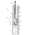
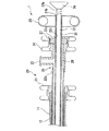
本発明の実施形態について図面を参照しながら詳細に説明する。図1は本実施形態における縫合器を含む内視鏡治療装置の概略図である。図2は縫合器の挿入部を示す断面図であり、図3は縫合器の手元操作部を主に示す断面図である。 Embodiments of the present invention will be described in detail with reference to the drawings. FIG. 1 is a schematic view of an endoscopic treatment apparatus including a suture instrument in the present embodiment. FIG. 2 is a cross-sectional view showing an insertion portion of the suturing device, and FIG. 3 is a cross-sectional view mainly showing a hand operation portion of the suturing device.
図1に示すように、本実施形態の縫合器1は、内視鏡治療装置2の鉗子チャンネル3に挿入されて用いられる。内視鏡治療装置2は、縫合器1を内挿した内視鏡4と、縫合器1に流体である空気などの気体を供給する流体供給手段であるエアポンプ7とからなる。さらに、内視鏡4は、体腔内に導入され、その先端に鉗子チャンネル3、照明やカメラのレンズなどを有する導入部5と、導入部5を体腔外から操作する操作部6とからなる。
As shown in FIG. 1, the
図2および図3に示すように縫合器1は、体腔内に挿入される軟性の挿入部10と、体腔外で施術者の操作を受け付ける手元操作部20とを有し、その内部に押出部材31,32を挿通させた構成になっている。
As shown in FIGS. 2 and 3, the
挿入部10は、可撓管である外側シース11と、外側シース11に進退可能に収容された内側シース12と、内側シース12の先端に取り付けられた穿刺針13とを有する。穿刺針13は、先端を鋭角に傾斜させて鋭利な尖部とし、生体組織への穿通を容易にしている。また、穿刺針13は、先端の尖部に開口14を有する中空形状をなし、この内腔に縫合糸15に取り付けられた係合部材16およびロック部材17を収容している。
The
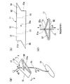
図2および図4(a)に示すように係合部材16は、円柱形状の部材からなり、その長手方向の中央付近に生体組織を挿通する縫合糸15の一端が係止されている。縫合時に係合部材16は、長手方向の広い面積で生体組織に当接し、係合させられて、縫合糸15が生体組織から抜け落ちることを防止する。このような形状および機能から、係合部材16は、T状アンカーまたはTバーと呼ばれることもある。
As shown in FIGS. 2 and 4A, the
ロック部材17は、縫合後の縫合糸15の抜け止めとして機能するもので、基部50に対して所定の角度を持って対向するように立ち上がる2つの折り曲げ片51,52を有し、係合部材16から引き出された縫合糸15の他端を基部50の孔50aと、折り曲げ片51,52との間に通すようになっている。図4(a)の斜視図、および図4(b)の展開図に示すように、ロック部材17は、板状部材の中央に縫合糸を通す孔50aを形成すると共に、板状部材の長辺方向の所定位置に設けた折り曲げ線53,54を折り曲げ位置として、端部を同じ方向に曲げて折り曲げ片51,52とし、孔50aを有する部分を生体組織に当接する当接面を有する基部50としている。折り曲げ片51の端部51aと、折り曲げ片52の端部52aとの間の距離は、縫合糸15がない状態で互いに接触するか、縫合糸15の直径以下になるようにする。
The
図4(a)のA−A線断面図である図4(c)に示すように、端部51aと端部52aとの間を引き離すようにして、基部50から端部51a,52aに向かって縫合糸15の他端を通すと、折り曲げ片51,52には互いに近接しようとする力が発生する。したがって、縫合糸15が基部50の方向d1に引っ張られると、端部51a,52aも方向d1に移動して、端部51a,52a間の距離が縮まり、縫合糸15を締め付けてロックし、縫合糸15の移動を防止する。つまり、ロック部材17は、係合部材16とロック部材17とを引き離す力が縫合糸15に働いた場合には、端部51aと端部52aを閉じるように移動させ、縫合糸15の動きをロックするように作用する。言い換えると、ロック部材17と係合部材16とで挟み込む縫合対象がロック部材17を縫合糸15の他端の方向d2に押そうとしても、端部51a,52aが縫合糸15を締め付けて縫合糸15に対するロック部材17の位置をロックするので、ロック部材17が方向d2に移動させられることはない。
As shown in FIG. 4C, which is a cross-sectional view taken along the line AA of FIG. 4A, the
一方、基部50と反対の方向d2に縫合糸15が引っ張られると、端部51a,52aも方向d2(互いに引き離される方向)に移動させられるので、縫合糸15の締め付けを解除する。つまり、係合部材16とロック部材17とを近付ける方向には縫合糸15の移動を許容するように作用する。言い換えると、縫合対象にロック部材17を押し付けるとき、つまりロック部材17を縫合糸15の一端の方向d1に移動させるときには、端部51aと端部52aとの間が開いて縫合糸15への端部51a,52aの締め付けが解除されるので、ロック部材17を方向d1に移動させることができる。
On the other hand, when the
また、このロック部材17は、折り曲げ片51,52から延設されて、縫合糸15を中央に安定して保持するためのガイド片55,56が設けられている。ガイド片55,56は、図4(b)の板材の短辺の中点から長辺の延長線上に斜めに延びる傾斜した端部55a,56aを備える三角形状を有している。ガイド片55とガイド片56とは、孔50aを中心として点対称となる位置に形成されているので、図4(a)のように折り曲げ片51,52を近接するように折り曲げても干渉することはない。傾斜する端部55a,55bは、縫合糸15をロック部材17の中央部分に安定して位置するようにガイドするので、縫合処置中に縫合糸15が折り曲げ片51,52の間から抜けることがなくなる。
Further, the
本実施形態では、係合部材16よりも穿刺針13の先端側にロック部材17を配置することで、係合部材16よりも大きい外形を有するロック部材17を用いることが可能になっている。また、穿刺針13の長さ方向(軸方向)と平行になるようにロック部材17の基部50を配置するので、穿刺針13の限られた収容スペースの中でも、生体組織と接触する基部50の面積、つまり当接面の面積を最大限に確保できるようになっている。
In the present embodiment, the
縫合糸15は、一端が係合部材16に固定されており、他端は末端処理として玉形状に結ばれている。端末処理は、ロック部材17を摺動可能に挿通した後に施され、ロック部材17の抜け落ちを防止する役割や、他の鉗子による把持を容易にする役割を担う。端末処理の他の例としては、縫合糸15の端部をリング状に結んだり、端部を溶かして塊状にしたりすることがあげられる。
One end of the
係合部材16およびロック部材17を穿刺針13から押し出す押出部材は、図2および図3に示すようにロック部材17を係合部材16よりも先に押し出す第一押出部材31と、係合部材16を押し出す第二押出部材32とからなり、共に手元操作部20側から内側シース12または穿刺針13に至るまで挿入されている。第一押出部材31は、穿刺針13の内径よりも小さい外径を有するパイプからなり、その内部に第二押出部材32および係合部材16を摺動可能に収容する。このため、その先端部分に係合部材16に取り付けられた縫合糸15を引き出すスリット31aが設けられている。なお、穿刺針12の内壁と第一押出部材31との間には、気体の通流を可能にする程度のクリアランスを設けることが望ましい。
The pushing member that pushes the engaging
図3に示す手元操作部20は、外側シース11に接続される保持部材21と、内側シース12に接続されて、穿刺針13を進退させる操作を行うために使用する穿刺針操作部22と、第一押出部材31の端部に取り付けられ、施術者が指を掛けるリングを備える押出部材ハンドル23と、第二押出部材32の端部に取り付けられた押出部材ノブ24とからなる。
3 includes a holding
穿刺針操作部22は、有底円筒形状を有し、その底部に相当する端部22aに術者が指を掛ける溝が形成されたノブ26を備え、開放された端部22bは内側シース12に接続されている。端部22aと端部22bとの間の側面には、穿刺針操作部22内に形成される空隙部分28に気体を導入する際に使用する流体導入部である送気ポート25を有する。この穿刺針操作部22には、第一押出部材31および第二押出部材32が端部22bから端部22aの開口22cへと貫通するように通されている。開口22cと第一押出部材31との間の気密はパッキン27により保持されているので、穿刺針操作部22内の空隙部分28から気体が流出することはない。穿刺針操作部22を保持部材21に対して相対的に進退させることで、体腔内で穿刺針13を外側シース11に対して進退させることができる。
The puncture
押出部材ハンドル23は、操作保持部22から引き出された第一押出部材31の外周に取り付けられている。押出部材ハンドル23を穿刺針操作部22に向かって押し込むと、穿刺針13からロック部材17を押し出すことができる。
押出部材ノブ24は、第一押出部材31の端部31bから引き出された第二押出部材32の端部32bに取り付けられている。押出部材ノブ24を押出部材ハンドル23および穿刺針操作部22に向かって押し込むと、穿刺針13から係合部材16を押し出すことができる。
The pushing member handle 23 is attached to the outer periphery of the first pushing
The pushing
送気ポート25に気体を供給する送気機構について図1を用いて説明する。送気機構は、大気を吸引し、所定の圧力で吐出するエアポンプ7を有し、エアポンプ7の吐出側に、送気と排気とを選択する電磁弁8aと、送気する気体の流量を調整する流量調整弁8bと、実際に供給される気体の流量をモニタする流量計8cとをこの順番に配管で接続し、CPU(Central Processing Unit)9で必要な制御を行う構成になっている。CPU9は、送気開始や送気停止を切り替えるフットスイッチまたはハンドスイッチからの命令信号を受け付けたり、流量計8cをモニタしたりしながら、電磁弁8aの切り替えと流量調整弁8bの開度調整とを行う。なお、流量計8cと送気ポート25との間も配管で接続されている。
An air supply mechanism for supplying gas to the
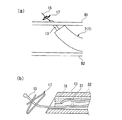
次に、この縫合器1で、器官などの組織を縫合する手順について図1から図3、および図5、図6、図7を適宜参照して説明する。なお、図5および図6は、縫合手順とそのときの押出部材の位置を説明する図であり、図7は縫合手順の説明図である。
Next, a procedure for suturing a tissue such as an organ with the
まず、図1の軟性内視鏡2と共に、図2に示す縫合器1の挿入部10を体腔内に導入する。このとき、手元操作部20の穿刺針操作部22は、保持部材21から所定量だけ引き出されているので、穿刺針13は、外側シース11内に収容されている。押出部材ハンドル23は、穿刺針操作部22から所定量だけ引き出されているので、第一押出部材31は、係合部材16を収容した状態でロック部材17を押圧しない位置まで後退している。押出部材ノブ24は、押出部材ハンドル23から所定量だけ引き出されているので、第二押出部材32は、第一押出部材32内で係合部材16を押圧しない位置まで後退している。
First, together with the
この状態から外側シース11の先端部を縫合させる生体組織に臨む位置まで移動させてから、穿刺針操作部材22を保持部材21に向けて所定量だけ押し込んで、穿刺針13を外側シース11から露出させる。そして、図示しないフットスイッチまたはハンドスイッチをオンして、図1に示すエアポンプ7が吐出する気体を送気ポート25に導く。送気ポート25に導かれた気体は、図3に示す穿刺針操作部材22の空隙部分28を経て挿入部10の内側シース12に導入される。そして、第一押出部材31と内側シース12および穿刺針13との間、ロック部材17と穿刺針13と間のクリアランスを通って、穿刺針13の先端の開口14から噴き出す。なお、ロック部材17は、穿刺針13の長さ方向と直交する方向において穿刺針13の内壁に当接しているので、気体の通流時にロック部材17が穿刺針13から脱落することはない。
From this state, the distal end portion of the
さらに、穿刺針操作部材22を押し込むと、先端から気体を噴き出しながら、穿刺針13が器官の生体組織を穿通する。器官は、穿刺針13から気体が供給されて膨らむ。所定量の気体を供給して、器官が処置に必要な程度膨らんだと判断したら、図示しないフットスイッチまたはハンドスイッチをオフして、送気ポート25への気体の供給を停止する。
Further, when the puncture
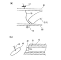
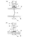
器官を膨らませた状態で、図3に示す押出部材ハンドル23を穿刺針操作部材22に向けて押し込むと、図5(b)に示すように第一押出部材31の先端が、ロック部材17を押圧して、穿刺針13の開口14からロック部材17を押し出す。図5(a)に示すようにロック部材17が縫合対象となる生体組織B1側に押し出されるので、穿刺針操作部材22を保持部材21から引き出すと、穿刺針13が後退して、生体組織B1から穿刺針13が抜ける。これにより、縫合糸15が生体組織B1を貫通すると共に、ロック部材17が生体組織B1に留置される。ロック部材17の基部50の中央に縫合糸15が通っているので、縫合糸15が引っ張られると基部50が生体組織B1に当接することになる。
When the push-out member handle 23 shown in FIG. 3 is pushed toward the puncture
次に、図示しない操作手段で、縫合器1を生体組織B2に臨む位置に移動させてから、穿刺針操作部材22を保持部材21に対して押し込んで、穿刺針13の先端から気体を噴き出させながら、図6(a)のように穿刺針13を生体組織B2に穿通させる。ここで、押出部材ノブ24(図3参照)を押出部材ハンドル23に向けて押し込むと、図6(b)に示すように第一押出部材31の先端よりも第二押出部材32が突出し、第一押出部材31内に収容されていた係合部材16を穿刺針13から押し出す。この後は、穿刺針操作部材22を引き戻して穿刺針13を生体組織B2から引き抜く。
Next, after the
これにより、図7(a)に示すように、縫合糸15が生体組織B2を貫通すると共に、係合部材16が生体組織B2に留置される。そして、鉗子71をシース72内に備えた他の処置器70でロック部材17から延びる縫合糸15を把持し、シース72の先端でロック部材17を基部50が生体組織B1に当接するように押さえつけながら、ロック部材17から縫合糸15を引き抜くようにして引っ張る。この方向は、前記したように端部51a,52aを開く方向であるので、ロック部材17は、縫合糸15の動きを許容する。したがって、縫合糸15に繋がっている係合部材16が引っ張られ、係合部材16が当接する生体組織B2が生体組織B1側に引っ張れ、図7(b)に示すように、生体組織B1と生体組織B2とが縫合される。このときに、ロック部材17は、生体組織B1と広い接触面積を有するので、確実なアンカー効果を発現し、ロック部材17が生体組織B1に食い込むことはない。また、前記したように、このロック部材17は、縫合糸15が折り曲げ片51,52から基部50に向かう向きに移動しようとすると端部51a,52aを閉じて締め付けるように作用する。したがって、生体組織B1と生体組織B2とが離れる方向には移動しないし、縫合糸15を移動させないので、縫合させた2つの生体組織B1,B2が離れることはない。
Thereby, as shown in FIG. 7A, the
なお、本発明は前記の各実施形態に限定されずに広く応用することが可能である。
例えば、ロック部材17は、図8に示す形状であっても良-い。図8(a),(b)に示すロック部材81は、長方形状の部材の短辺方向を同じ折り曲げて、折り曲げ片82,83を形成している。近接させた折り曲げ片82の端部と折り曲げ片83の端部との間に、折り曲げ片82,83の折り曲げ位置から端部に向かう方向に縫合糸15を通すことで、前記と同様に縫合糸15の締め付けや、締め付けの解除といったロック機能を実現する。この場合は細長形状を有し、最も面積の大きい基部84が生体組織に当接する接触面となる。
The present invention is not limited to the above embodiments and can be widely applied.
For example, the
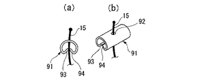
また、図9(a),(b)に示すロック部材91は、断面が円弧状の細長の部材の中央に縫合糸15を通す孔92を設け、長辺と直交する端部を孔92の方に折り曲げて折り曲げ片93,94を形成している。このロック部材91も、近接する折り曲げ片93の端部と折り曲げ片94の端部の間に、折り曲げ片93,94の折り曲げ位置から端部に向かう方向に縫合糸15を通すことで、前記と同様にロック機能を実現する。このロック部材91は、孔92と対向する面が基部、つまり生体組織に当接する接触面となる。
9A and 9B, a
図10のロック部材101は、細長形状の板材の中央部分にH形状の切り込みを入れて折り曲げ片102,103を切り起こした形状を有する。前記のような孔は有しないが、近接するように傾斜させた折り曲げ片102の端部と、折り曲げ片103の端部との間に、折り曲げ片102,103の折り曲げ位置から端部に向かう方向に縫合糸15を通すことで、前記と同様にロック機能を実現する。
このロック部材101は、折り曲げ片102,103を除く部分が基部として生体組織に当接する接触面となる。なお、図8から図10に示した各ロック部材81,91,101も、接触面が穿刺針13の軸方向と平行になるようにその内腔に収容される。また、係合部材16よりも穿刺針13の先端側に配置される。
The
In the
また、穿刺針13の先端から噴き出させる流体は、空気やその他の気体であっても良いが、生理食塩水などの液体であっても良い。
The fluid ejected from the tip of the
15 縫合糸
16 係合部材
17 ロック部材
50 基部
51 折り曲げ片
51a 端部
52 折り曲げ片
52a 端部
15
Claims (4)
前記ロック部材は、互いに対向するように基部に対して傾斜させた2つの折り曲げ片を有し、前記折り曲げ片は、その対向する端部が閉じるように力が作用したときに前記端部間に通された前記縫合糸を締め付け、対向する前記端部が開くように力が作用したときに前記縫合糸の締め付けを解除するように構成され、
前記ロック部材は、略中央に前記縫合糸を通す孔が形成された板状部材により形成され、該板状部材の長辺方向の両側の所定位置を折り曲げ位置として、90度以上折り曲げることによって側面視3角形を形成するように、前記基部の左右両側に前記折り曲げ片が形成され、
前記孔を有する前記基部の外側面が生体組織に当接する当接面を構成することを特徴とする縫合具。 An engagement member attached to one end of the suture and engaged with the biological tissue, and inserted into the other end of the suture, and functions as a stopper for the suture to come into contact with the biological tissue penetrated by the suture. And a locking member
The lock member has two bent pieces that are inclined with respect to the base so as to face each other, and the bent pieces are placed between the ends when a force is applied to close the opposite ends. It is configured to tighten the passed suture and to release the tightening of the suture when a force is applied so that the opposite ends are opened .
The lock member is formed by a plate-like member having a hole through which the suture thread is passed at a substantially center, and is bent by 90 degrees or more with a predetermined position on both sides in the long side direction of the plate-like member as a bending position. The bent pieces are formed on the left and right sides of the base so as to form a triangular view,
A suturing tool, wherein an outer surface of the base having the hole constitutes a contact surface that contacts a living tissue .
Priority Applications (1)
| Application Number | Priority Date | Filing Date | Title |
|---|---|---|---|
| JP2006153367A JP4145331B2 (en) | 2006-06-01 | 2006-06-01 | Suture and endoscope |
Applications Claiming Priority (1)
| Application Number | Priority Date | Filing Date | Title |
|---|---|---|---|
| JP2006153367A JP4145331B2 (en) | 2006-06-01 | 2006-06-01 | Suture and endoscope |
Related Parent Applications (1)
| Application Number | Title | Priority Date | Filing Date |
|---|---|---|---|
| JP2003162009A Division JP4166632B2 (en) | 2003-06-06 | 2003-06-06 | Suture device |
Publications (2)
| Publication Number | Publication Date |
|---|---|
| JP2006239455A JP2006239455A (en) | 2006-09-14 |
| JP4145331B2 true JP4145331B2 (en) | 2008-09-03 |
Family
ID=37046382
Family Applications (1)
| Application Number | Title | Priority Date | Filing Date |
|---|---|---|---|
| JP2006153367A Expired - Fee Related JP4145331B2 (en) | 2006-06-01 | 2006-06-01 | Suture and endoscope |
Country Status (1)
| Country | Link |
|---|---|
| JP (1) | JP4145331B2 (en) |
Families Citing this family (6)
| Publication number | Priority date | Publication date | Assignee | Title |
|---|---|---|---|---|
| JP2008148933A (en) * | 2006-12-18 | 2008-07-03 | Yoshikawa Kasei Kk | Placement device of internal organ fixing appliance |
| US7780702B2 (en) * | 2007-02-27 | 2010-08-24 | Olympus Medical Systems Corp. | Suture tool |
| US8070772B2 (en) * | 2008-02-15 | 2011-12-06 | Rex Medical, L.P. | Vascular hole closure device |
| US20090259232A1 (en) * | 2008-04-11 | 2009-10-15 | Junji Shiono | Suture device |
| US8911454B2 (en) * | 2008-07-31 | 2014-12-16 | Olympus Medical Systems Corp. | Suturing device |
| US11304691B2 (en) | 2016-11-13 | 2022-04-19 | Anchora Medical Ltd. | Minimally-invasive tissue suturing device |
-
2006
- 2006-06-01 JP JP2006153367A patent/JP4145331B2/en not_active Expired - Fee Related
Also Published As
| Publication number | Publication date |
|---|---|
| JP2006239455A (en) | 2006-09-14 |
Similar Documents
| Publication | Publication Date | Title |
|---|---|---|
| JP4166632B2 (en) | Suture device | |
| JP4145200B2 (en) | Suture device | |
| JP5185544B2 (en) | Suture system | |
| US6024747A (en) | Device and method for suturing blood vessels and the like | |
| JP4790549B2 (en) | Suture tool | |
| US9788831B2 (en) | Endoscopic suture cinch system with replaceable cinch | |
| US6428549B1 (en) | Device and method for suturing blood vessels and the like | |
| JP4116049B2 (en) | Biological tissue clip device | |
| US10448946B2 (en) | Endoscopic suture cinch | |
| US5480407A (en) | Suturing instrument with hemorrhaging control | |
| KR101423341B1 (en) | Suturing device | |
| US20050216036A1 (en) | Endoscopic fastening system with multiple fasteners | |
| US9101345B2 (en) | Surgical guide and tissue anchor | |
| US20080234729A1 (en) | Suture lock fastening device | |
| CN101637398B (en) | stapler | |
| JP2003225241A (en) | Therapeutic manipulator for endoscope | |
| US9301748B2 (en) | Suture apparatus, system and method | |
| JP6888556B2 (en) | Endoscopic suture ligature | |
| JP4145331B2 (en) | Suture and endoscope |
Legal Events
| Date | Code | Title | Description |
|---|---|---|---|
| A521 | Request for written amendment filed |
Free format text: JAPANESE INTERMEDIATE CODE: A821 Effective date: 20060602 |
|
| A621 | Written request for application examination |
Free format text: JAPANESE INTERMEDIATE CODE: A621 Effective date: 20060601 |
|
| A131 | Notification of reasons for refusal |
Free format text: JAPANESE INTERMEDIATE CODE: A131 Effective date: 20080212 |
|
| A521 | Request for written amendment filed |
Free format text: JAPANESE INTERMEDIATE CODE: A523 Effective date: 20080414 |
|
| A521 | Request for written amendment filed |
Free format text: JAPANESE INTERMEDIATE CODE: A821 Effective date: 20080416 |
|
| TRDD | Decision of grant or rejection written | ||
| A01 | Written decision to grant a patent or to grant a registration (utility model) |
Free format text: JAPANESE INTERMEDIATE CODE: A01 Effective date: 20080610 |
|
| A01 | Written decision to grant a patent or to grant a registration (utility model) |
Free format text: JAPANESE INTERMEDIATE CODE: A01 |
|
| A61 | First payment of annual fees (during grant procedure) |
Free format text: JAPANESE INTERMEDIATE CODE: A61 Effective date: 20080617 |
|
| R151 | Written notification of patent or utility model registration |
Ref document number: 4145331 Country of ref document: JP Free format text: JAPANESE INTERMEDIATE CODE: R151 |
|
| FPAY | Renewal fee payment (event date is renewal date of database) |
Free format text: PAYMENT UNTIL: 20110627 Year of fee payment: 3 |
|
| FPAY | Renewal fee payment (event date is renewal date of database) |
Free format text: PAYMENT UNTIL: 20120627 Year of fee payment: 4 |
|
| FPAY | Renewal fee payment (event date is renewal date of database) |
Free format text: PAYMENT UNTIL: 20120627 Year of fee payment: 4 |
|
| FPAY | Renewal fee payment (event date is renewal date of database) |
Free format text: PAYMENT UNTIL: 20130627 Year of fee payment: 5 |
|
| S531 | Written request for registration of change of domicile |
Free format text: JAPANESE INTERMEDIATE CODE: R313531 |
|
| R350 | Written notification of registration of transfer |
Free format text: JAPANESE INTERMEDIATE CODE: R350 |
|
| R250 | Receipt of annual fees |
Free format text: JAPANESE INTERMEDIATE CODE: R250 |
|
| R250 | Receipt of annual fees |
Free format text: JAPANESE INTERMEDIATE CODE: R250 |
|
| R250 | Receipt of annual fees |
Free format text: JAPANESE INTERMEDIATE CODE: R250 |
|
| LAPS | Cancellation because of no payment of annual fees |

