JP4145062B2 - Rotating damper - Google Patents
Rotating damper Download PDFInfo
- Publication number
- JP4145062B2 JP4145062B2 JP2002090379A JP2002090379A JP4145062B2 JP 4145062 B2 JP4145062 B2 JP 4145062B2 JP 2002090379 A JP2002090379 A JP 2002090379A JP 2002090379 A JP2002090379 A JP 2002090379A JP 4145062 B2 JP4145062 B2 JP 4145062B2
- Authority
- JP
- Japan
- Prior art keywords
- bearing
- rotating body
- casing
- damping force
- fluid
- Prior art date
- Legal status (The legal status is an assumption and is not a legal conclusion. Google has not performed a legal analysis and makes no representation as to the accuracy of the status listed.)
- Expired - Fee Related
Links
Images


Landscapes
- Fluid-Damping Devices (AREA)
Description
【0001】
【発明の属する技術分野】
この発明は、ケーシングに対して回転体を相対回転させる過程で、一定の減衰力を発揮するとともに、その減衰力を微調整可能にした回転ダンパーに関する。
【0002】
【従来の技術】
減衰力を微調整可能にした回転ダンパーとして、特開平5−263848号公報に記載された発明が従来から知られているが、それを示したのが図11および図12である。これら図面からも明らかなように、従来の回転ダンパーは、一端をキャップ1でふさいだケーシング2に、回転体3を組み込むとともに、この回転体3に一体に設けた回転軸4をケーシング2の外方に突出させている。
【0003】
上記ケーシング2には、その直径方向に突出させた一対の区画壁5、6を形成しているが、回転体3はこの区画壁5、6に接触しながら回転するとともに、その接触部に十分なシール機能をもたせている。一方、回転体3にはその直径方向に一対の制御片7、8を形成するとともに、この制御片7、8の先端にケーシング2の内周に接触する減衰力発生手段9、10を設けている。このように減衰力発生手段9、10をケーシング2の内周に接触させることによって、ケーシング2の一方の半円部分に第1流体室11と第2流体室12とが形成され、他方の半円部分にも第1流体室13と第2流体室14とが形成される。
【0004】
上記のようにした上記減衰力発生手段9、10は次のように機能する。すなわち、回転体3が矢印15方向に回転すると、第1流体室11、13の体積が縮小され、第2流体室12、14の体積が拡大する。このとき制御片7、8の切欠き溝7a、8aが減衰力発生手段9、10の側壁に接触してふさがれることになる。したがって、体積が縮小する第1流体室11、13内の流体は、減衰力発生手段9、10とケーシング2の内周面との接触面を通って、体積が拡大する第2流体室12、14側に流出するが、このときの流動抵抗が減衰力となる。
【0005】
一方、回転体3が上記矢印15とは反対方向に回転すると、今度は、第2流体室12、14の体積が縮小され、第1流体室11、13の体積が拡大する。このとき制御片7、8の切欠き溝7a、8aは、減衰力発生手段9、10に形成した切欠き部9a、10aと一致する。したがって、体積が縮小する第2流体室12、14内の流体は、切欠き部9a、10aおよび切欠き溝7a、8aを通って、体積が拡大する第1流体室11、13側に流出するが、このときにはその流動抵抗はほとんど発生しない。以上のことからも明らかなように、回転体3が矢印15方向に回転したとき、大きな減衰力が発生するので一定のダンパー効果が発揮される。しかし、回転体3が矢印15とは反対方向に回転したときには、ダンパー効果はほとんど発揮されない。
【0006】
上記のようにした回転体3には、互いにクロスさせた一対の貫通孔16、17を形成しているが、一方の貫通孔16は、その開口16a、16bを第1流体室11、13側に開口させ、他方の貫通孔17は、その開口17a、17bを第2流体室12、14側に開口させている。このような構成のもとで、回転体3が矢印15方向に回転すると、第1流体室11、13が高圧になるので、その第1流体室11、13の高圧流体は、開口16a、16bから開口17a、17bを通って第2流体室12、14に流れる。
【0007】
上記のようにした貫通孔16、17のクロス部分には、円形の交差孔18を形成するとともに、この交差孔18には、キャップ1に設けた調整ネジ19の先端が出入しうるようにしている。そして、調整ネジ19の先端と、その先端に対向する交差孔18の底部18aとの間隔の大きさによって、貫通孔16、17の流通有効径が異なるようにしている。つまり、間隔が大きくなればなるほど、その流通有効径が大きくなり、それだけ流路抵抗も小さくなる。
【0008】
上記の構成において、当該回転ダンパーのダンパー効果は、シリンダ2の内周と減衰力発生手段9、10とのすき間によって発生する減衰力で決まる。ただし、調整ネジ19を回して、調整ネジ19と交差孔18の底部18aとの間隔を調整することによって、その減衰力の微調整が可能なようにしている。したがって、この従来の回転ダンパーでは、当該ダンパーの使用目的等に応じて、ダンパー効果を微妙に調整できる。
【0009】
【発明が解決しようとする課題】
上記のようにした従来の回転ダンパーでは、回転体に形成した貫通孔をもって減衰力の微調整用の流路としているが、回転体に貫通孔を形成するには、その孔形成が非常に難しくなるという問題があった。例えば、貫通孔を含めて回転体を型形成しようとすると、その型を抜くことを考慮しなければならないので、割型の数が多くならざるを得ない。割型が多くなればそれだけ製造コストがかさんでしまう。また、貫通孔をドリル等で切削加工することも考えられる。しかし、この切削加工も決して簡単ではない。いずれにしても、上記したように従来の回転ダンパーは製造が非常に難しいという問題があった。
この発明の目的は、製造が簡単な回転ダンパーを提供することである。
【0010】
【課題を解決するための手段】
この発明は、ケーシングに回転体を相対回転自在に組み込むとともに、回転体に設けた制御片とケーシングに設けた区画壁とで第1流体室と第2流体室とを区画し、減衰力発生手段を介して上記両流体室を連通させる。一方、減衰力発生手段を経由する流路とは別に、両流体室を連通する短絡通路を設け、この短絡通路には絞り部を設けるとともに、その絞り部の開度を可変にする可変絞り機構を設けている。そして、上記回転体には、軸受け凹部および軸受け凸部のいずれか一方を形成し、上記ケーシングには、軸受け凹部および軸受け凸部のいずれか他方を形成し、上記回転体に形成した軸受け凹部または軸受け凸部と、上記ケーシングに形成した軸受け凸部または軸受け凹部とを相対回転自在に嵌め込んで軸受け機能を発揮させるとともに、上記軸受け凹部と軸受け凸部との接触面に連通溝を形成して、この連通溝によって上記短絡通路を構成することを特徴とする。
【0011】
上記の構成において、回転体をケーシングに対して相対的にいずれかに回転させることによって、一方の流体室の流体が減衰力発生手段を経由して他方の流体室に流入する。このように減衰力発生手段を流体が流通することによって、所定の減衰力を発生し初期のダンパー効果を発揮する。なお、減衰力発生手段は、回転体の両方向の回転に対して減衰力を発生させるものであってもよいし、いずれか一方向の回転だけに減衰力を発生させるものであってもよい。さらに、上記流体室は、第1流体室と第2流体室とを一組にして、何組設けてもよい。
【0012】
【発明の実施の形態】
図1〜図4に示す第1実施例において、円筒状のケーシングcは、その一方を側壁20でふさぎ、他方をキャップ21でふさぐようにしているもので、このキャップ21はケーシングcに対してネジで止めるようにしている。
また、上記ケーシングcに組み込む回転体22は、図1に示すように、一方の側面に回転軸23を設ける一方、この回転軸23とは反対面に軸受け凹部24を形成している。そして、この軸受け凹部24は、ケーシングcの側壁20に形成した軸受け凸部25にはめ合わせることによって、そのはめ合わせ部分が回転自在に支持されるようにしている。さらに、上記回転軸23は、キャップ21に設けた軸受けブッシュ26で回転自在に支持されている。したがって、回転体22および回転軸23は、それらの軸線を中心にして、回転自在に支持されるものである。
【0013】
上記のようにしたケーシングcの内周には、その直径方向において対向する一対の区画壁27、28を設けているが、ケーシングcに組み込まれた回転体22はこの区画壁27、28に接触するとともに、その接触部分のシール性を十分に保っている。
また、上記回転体22は、その直径方向に一対の制御片29、30を設けるとともに、この制御片29、30の先端に弁機構31、32を設けている。そして、この弁機構31、32をケーシングcの内周に接触させることによって、区画壁27、28を境にして、一方の半円側に第1流体室33と第2流体室34とを形成し、他方の半円側にも第1流体室35と第2流体室36とを区画形成している。
【0014】
上記弁機構31、32は、第2流体室34、36側に常時開口する凹部37、38を形成し、回転体22が矢印39方向に回転したとき、その回転方向の圧力作用で図2の状態から少し回るともに、凹部37、38を介して第2流体室34、36を第1流体室33、35に連通させる。しかし、回転体22が上記矢印39とは反対方向に回転したときには、その回転方向の圧力作用で図2の状態を保ち、凹部37、38を介しての両室の連通は遮断される。ただし、凹部37、38が閉じたとしても、第1流体室33、35と第2流体室34、36とは、弁機構31、32とケーシングcとの間のわずかのすき間を介して連通するようにしている。つまり、この第1実施例では、回転体22の一方の回転に対して減衰力が大きくなり、他方の回転に対しては減衰力が小さくなるようにしている。
【0015】
なお、図中符号40は軸受け凸部25にかぶせた樹脂製のブッシュで、回転体22と軸受け凸部25とが金属製なので、それら金属が直接擦れ合うのを防止するためのものである。また、符号41は、回転体22とキャップ21との間に介在させたワッシャで、Oリングを保持するためのものである。
【0016】
上記のようにした回転体22の軸受け凹部24には、図4からも明らかなように、互いにクロスする一対の連通溝42、43を形成している。そして、一方の連通溝42の開口端42aおよび42bは、制御片29、30に隣接する位置において第1流体室33、35側に開口させている。また、他方の連通溝43の開口端43aおよび43bは、制御片29、30に隣接する位置において第2流体室34、36側に開口させている。このようにした一対の連通溝42、43が交差する部分には円形の凹部からなる絞り部44を形成している。
【0017】
また、前記軸受け凸部25には、ケーシングcの外部から調整ネジ45を挿入し、この調整ネジ45の先端が、絞り部44に出入しうるようにしている。そして、調整ネジ45の先端と絞り部44とはそれらがはまる寸法関係を維持するとともに、絞り部44の直径を連通溝42、43の溝幅よりも大きくしている。
【0018】
上記のように回転体22の軸受け凹部24に連通溝42、43を形成することことによって、凹部24と軸受け凸部25とをはめ合わせたとき、これら連通溝42、43とブッシュとが相まってこの発明の短絡通路を構成するものである。
なお、この発明では、ケーシングの内面と回転体との接触面であって、ケーシングあるいは回転体のいずれか一方に連通溝を形成し、ケーシングに回転体を組み込んだとき連通溝が短絡通路を構成するとしているが、これはケーシングcに設けたブッシュ40をそのケーシングの一部としてとらえたものである。つまり、この発明としては、ブッシュ40は必ずしも必須の構成要素ではない。
【0019】
いずれにしても連通溝42、43を主要素としてなる短絡通路は、その一方の開口端42a、42bが第1流体室33、35側に開口し、他方の開口端43a、43bが第2流体室34、36に開口する。したがって、第1流体室33、35が高圧になると、その高圧流体は、一方の開口端42a、42bから他方の開口端43a、43bを経由して第2流体室34、36に流れる。
【0020】
そして、この短絡通路の絞り部44の開度は、その絞り部44に対する調整ネジ45の出入量によって決まる。例えば、調整ネジ45の先端が絞り部44から完全に退出した状態では、その絞り部44の開度が最大になる。反対に、調整ネジ45の先端が絞り部44内に完全に入った状態では、その絞り部44が閉じられることになる。このように絞り部44が閉じてしまえば、第1流体室33、35と第2流体室34、36とが、短絡通路を介して連通することはなくなる。
ただし、調整ネジ45が最も奥まで挿入された状態で、絞り部44が完全に閉じなくてもよい。完全に閉じない場合には、短絡通路に流体がわずかに流れることになる。
【0021】
なお、図1中、符号46は回転体22および回転軸23内に設けたアキュムレータで、スプリング47のバネ力を付与されたピストン48を主要素にしてなる。ただし、このスプリング47のバネ力は、プラグ49を回して軸方向の位置を変えることによって調整できるようにしている。そして、上記ピストン48には、絞り部44の圧力が作用するようにしている。したがって、何らかの原因で、第1流体室33、35の圧力が急上昇したとしても、アキュムレータ46によってその衝撃を吸収することができる。
【0022】
次に、第1実施例の作用を説明する。
今、回転体22が矢印39方向に回転すると、弁機構31、32が少し回転し、第2流体室34、36とが凹部37、38を介して連通する。したがって、第2流体室34、36内の流体が、第1流体室33、35にスムーズに流れる。このように第2流体室34、36内の流体が第1流体室33、35にスムーズに流れるので、上記矢印39方向の回転はほとんど自由回転に等しくなる。
【0023】
回転体22を矢印39とは反対方向に回転させると、弁機構31、32が図示の状態を保つので、凹部37、38を介しての連通は遮断される。したがって、第1流体室33、35内の流体は、弁機構31、32とケーシングcの内周面との間のわずかなすき間を通って第2流体室34、36に流れる。このように流体がわずかなすき間を通るときの流動抵抗が減衰力となって所定のダンパー効果を発揮することになる。
なお、上記のことからも明らかなように、上記弁機構31、32は、それがダンパー効果を発揮するときに、この発明の減衰力発生手段を構成するものである。したがって、この発明の減衰力発生手段は、上記弁機構に限定されるものではなく、いろいろな構成のものが考えられる。要は、回転体の回転に対して減衰力を発生するものであればどのようなものであってもよい。また、弁機構を設けることなく、制御片29、30とケーシングcとの間に形成されるすき間をもって減衰力発生手段としてもよい。
【0024】
上記のようにして回転体22が矢印39とは反対方向に回転するときに所定のダンパー効果を発揮するが、絞り部44の開度を調節することによって、ダンパー効果を微調整することができる。例えば、絞り部44の開度を大きくすれば、減衰力が小さくなる方向の微調整となり、反対に絞り部44の開度を小さくすれば、減衰力が大きくなる方向の微調整となる。そして、この減衰力の大小に応じてダンパー効果が異なるので、当該ダンパーの用途等に応じて、最適なダンパー効果を得ることができる。
【0025】
また、この第1実施例では、短絡通路を連通溝42、43で構成するようにしているが、この連通溝42、43は回転体22の軸受け凹部24の内面に形成すれば足りることになる。したがって、当該凹部24を形成する際の雄型に凸部を形成しておけばよいことになり、従来のように貫通孔16、17を形成する必要がない。このように雄型に凸部を形成するだけで足りるので、従来のダンパーと比較してその製造コストを低く抑えることができる。
なお、上記第1実施例において、回転体22の衝撃を吸収するアキュムレータ46を設けたが、このアキュムレータ46はこの発明の必須の構成要素ではない。
【0026】
上記のようにアキュムレータ46を設けない場合には、図5に示した第2実施例のように、第1実施例のアキュムレータ46の位置に調整ネジ45を設けることができる。言い換えると、この発明においては、調整ネジ45をケーシング側に設けてもよいし、回転体22側に設けてもよいものである。ただし、機能的には第2実施例も第1実施例とまったく同様である。
【0027】
図6および図7に示した第3実施例は、連通溝50、51を、軸受け凸部25の表面に形成したもので、この連通溝50、51とアキュムレータ46の有無とが第1実施例と相違し、その他は、第1実施例と同様である。ただし、この第3実施例の場合には、連通溝50、51の開口端50a、50bおよび51a、51bのそれぞれを、区画壁27、28の近傍に設けている。このように開口端50a〜51bを区画壁27、28の近傍に設けたのは、制御片29、30がどのような位置にあっても、上記各開口端を第1流体室あるいは第2流体室に常時開口させるためである。また、この第3実施例の場合にも、調整ネジ45を出入させることによって絞り部44の開度を調整し、減衰力を微調整できること第1実施例とまったく同様である。
【0028】
図8および図9に示した第4実施例は、回転体22の先端に軸受け凸部52を形成し、この軸受け凸部52の周囲と端面に連通溝53、54を形成したものである。そして、ケーシングcの壁面に軸受け凹部55を形成し、この軸受け凹部55に上記軸受け凸部52をはめ込んだものである。なお、図中符号56は軸受け凹部55内に設けた樹脂製のブッシュである。
上記のようにした連通溝53、54の開口端53a、53bおよび54a、54bのそれぞれは、回転体22の表面であって、制御片29、30に隣接位置に形成している。そして、上記連通溝53、54が交差する部分に円形の凹部からなる絞り部57を形成している。
また、上記ケーシングcには、調整ネジ45を設け、この調整ネジ45の先端を上記絞り部57に出入させることによって、絞り部57の開度を調整すること第1実施例と同様である。したがって、減衰力の微調整の機能も第1実施例と同様である。
【0030】
【発明の効果】
この発明の回転ダンパーによれば、回転体とケーシングとの接触面に連通溝を形成し、ケーシングに回転体を組み込んだとき連通溝が短絡通路を構成するようにしたので、短絡通路を設けるために、従来のような貫通孔を形成する必要がない。このように溝形成だけで足りるので、それを型形成する場合にも、削り出しで形成する場合にも、その製造コストを大幅に改善することができる。
【図面の簡単な説明】
【図1】 第1実施例を示すもので軸線に沿った断面図である。
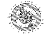
【図2】 第1実施例を示すもので軸線に直交する方向の断面図である。
【図3】 第1実施例の側面図で、その一部を切り欠いたものである。
【図4】 第1実施例の軸受け凹部を正面にした図である。
【図5】 第2実施例を示すもので軸線に沿った断面図である。
【図6】 第3実施例を示すもので軸線に沿った断面図である。
【図7】 第3実施例を示すもので軸線に直交する方向の断面図である。
【図8】 第4実施例を示すもので軸線に沿った断面図である。
【図9】 第4実施例を示す要部の斜視図である。
【図10】 従来の回転ダンパーを示す軸線に沿った断面図である。
【図11】 従来の回転ダンパーを示すもので、軸線に直交する方向の断面図である。 [0001]
BACKGROUND OF THE INVENTION
The present invention relates to a rotary damper that exhibits a constant damping force in the process of rotating a rotating body relative to a casing, and that allows the damping force to be finely adjusted.
[0002]
[Prior art]
As a rotary damper in which the damping force can be finely adjusted, an invention described in Japanese Patent Laid-Open No. 5-263848 has been conventionally known, and FIGS. 11 and 12 show this. As is clear from these drawings, the conventional rotary damper incorporates the
[0003]
The
[0004]
The damping force generating means 9 and 10 configured as described above function as follows. That is, when the rotating
[0005]
On the other hand, when the
[0006]
The rotating
[0007]
A
[0008]
In the above configuration, the damper effect of the rotary damper is determined by the damping force generated by the gap between the inner periphery of the
[0009]
[Problems to be solved by the invention]
In the conventional rotary damper as described above, the through hole formed in the rotating body is used as a flow path for fine adjustment of the damping force. However, in order to form a through hole in the rotating body, it is very difficult to form the hole. There was a problem of becoming. For example, an attempt to mold a rotating member including a through-hole, because it must be considered that to pull the mold, inevitably has many number of split mold. The more split molds, the higher the manufacturing cost. It is also conceivable to cut the through hole with a drill or the like. However, this cutting process is never easy. In any case, as described above, the conventional rotary damper has a problem that it is very difficult to manufacture.
An object of the present invention is to provide a rotary damper that is easy to manufacture.
[0010]
[Means for Solving the Problems]
According to the present invention, a rotating body is incorporated in a casing so as to be relatively rotatable, and a first fluid chamber and a second fluid chamber are partitioned by a control piece provided in the rotating body and a partition wall provided in the casing, thereby generating a damping force. The fluid chambers are communicated with each other via On the other hand, in addition to the flow path through the damping force generating means, a short-circuit passage that communicates both fluid chambers is provided, and the short-circuit passage is provided with a throttle portion and a variable throttle mechanism that makes the opening of the throttle portion variable. Is provided. The rotating body is formed with one of a bearing recess and a bearing protrusion, and the casing is formed with either the bearing recess or the bearing protrusion, and the bearing recess formed on the rotating body or The bearing convex portion and the bearing convex portion or the bearing concave portion formed on the casing are fitted so as to be relatively rotatable so as to exert a bearing function, and a communication groove is formed on a contact surface between the bearing concave portion and the bearing convex portion. The short-circuit passage is constituted by the communication groove.
[0011]
In the above configuration, by rotating the rotating body relative to the casing, the fluid in one fluid chamber flows into the other fluid chamber via the damping force generating means. In this way, when the fluid flows through the damping force generating means, a predetermined damping force is generated and the initial damper effect is exhibited. The damping force generation means may generate a damping force with respect to the rotation of the rotating body in both directions, or may generate a damping force only in any one direction of rotation. Further, any number of the fluid chambers may be provided by combining the first fluid chamber and the second fluid chamber.
[0012]
DETAILED DESCRIPTION OF THE INVENTION
In the first embodiment shown in FIGS. 1 to 4, a cylindrical casing c is configured such that one side is closed by a
Further, as shown in FIG. 1 , the rotating
[0013]
A pair of
Further, the rotating
[0014]
The
[0015]
In the figure,
[0016]
As is apparent from FIG. 4, a pair of
[0017]
An
[0018]
By forming the
In the present invention, the contact surface between the inner surface of the casing and the rotating body is formed with a communication groove in either the casing or the rotating body, and the communication groove constitutes a short-circuit path when the rotating body is incorporated in the casing. In this case, the
[0019]
In any case, in the short-circuit passage having the
[0020]
The opening degree of the
However, the restricting
[0021]
In FIG. 1,
[0022]
Next, the operation of the first embodiment will be described.
Now, when the
[0023]
When the
As is clear from the above, the
[0024]
A predetermined damper effect is exhibited when the
[0025]
Further, in this first embodiment, the short-circuit passage is constituted by the
In the first embodiment, the
[0026]
When the
[0027]
In the third embodiment shown in FIGS. 6 and 7, the
[0028]
In the fourth embodiment shown in FIGS. 8 and 9, a bearing
Each of the open ends 53a, 53b and 54a, 54b of the
The casing c is provided with an adjusting
[0030]
【The invention's effect】
According to the rotary damper of the present invention, the communication groove is formed in the contact surface between the rotating body and the casing, and when the rotating body is incorporated in the casing, the communication groove constitutes the short-circuit path. In addition, it is not necessary to form a through hole as in the prior art. Since only groove formation is sufficient in this way, the manufacturing cost can be greatly improved both when the die is formed and when it is formed by cutting.
[Brief description of the drawings]
FIG. 1 is a cross-sectional view along an axis showing a first embodiment.
FIG. 2 shows a first embodiment and is a cross-sectional view in a direction perpendicular to the axis.
FIG. 3 is a side view of the first embodiment, which is partially cut away.
FIG. 4 is a front view of a bearing recess according to the first embodiment.
FIG. 5 is a cross-sectional view along an axis showing a second embodiment.
FIG. 6 is a cross-sectional view along an axis showing a third embodiment.
FIG. 7 shows a third embodiment and is a cross-sectional view in a direction perpendicular to the axis.
FIG. 8 shows a fourth embodiment and is a cross-sectional view along the axis.
FIG. 9 is a perspective view of an essential part showing a fourth embodiment.
FIG. 10 is a cross-sectional view along an axis showing a conventional rotary damper.
FIG. 11 is a cross-sectional view showing a conventional rotary damper in a direction perpendicular to the axis.
Claims (1)
Priority Applications (1)
| Application Number | Priority Date | Filing Date | Title |
|---|---|---|---|
| JP2002090379A JP4145062B2 (en) | 2002-03-28 | 2002-03-28 | Rotating damper |
Applications Claiming Priority (1)
| Application Number | Priority Date | Filing Date | Title |
|---|---|---|---|
| JP2002090379A JP4145062B2 (en) | 2002-03-28 | 2002-03-28 | Rotating damper |
Publications (3)
| Publication Number | Publication Date |
|---|---|
| JP2003287076A JP2003287076A (en) | 2003-10-10 |
| JP2003287076A5 JP2003287076A5 (en) | 2005-09-15 |
| JP4145062B2 true JP4145062B2 (en) | 2008-09-03 |
Family
ID=29235700
Family Applications (1)
| Application Number | Title | Priority Date | Filing Date |
|---|---|---|---|
| JP2002090379A Expired - Fee Related JP4145062B2 (en) | 2002-03-28 | 2002-03-28 | Rotating damper |
Country Status (1)
| Country | Link |
|---|---|
| JP (1) | JP4145062B2 (en) |
Cited By (1)
| Publication number | Priority date | Publication date | Assignee | Title |
|---|---|---|---|---|
| CN105889309A (en) * | 2015-02-13 | 2016-08-24 | 日本电产三协株式会社 | Fluid damper device and apparatus equipped with damper |
Families Citing this family (3)
| Publication number | Priority date | Publication date | Assignee | Title |
|---|---|---|---|---|
| JP6167268B2 (en) * | 2013-08-09 | 2017-07-26 | 株式会社Tok | Torque automatic adjustment type rotary damper |
| JP6480155B2 (en) * | 2014-11-11 | 2019-03-06 | オイレス工業株式会社 | Rotary damper |
| JP2016148439A (en) * | 2015-02-13 | 2016-08-18 | 日本電産サンキョー株式会社 | Fluid damper device and apparatus with damper |
-
2002
- 2002-03-28 JP JP2002090379A patent/JP4145062B2/en not_active Expired - Fee Related
Cited By (1)
| Publication number | Priority date | Publication date | Assignee | Title |
|---|---|---|---|---|
| CN105889309A (en) * | 2015-02-13 | 2016-08-24 | 日本电产三协株式会社 | Fluid damper device and apparatus equipped with damper |
Also Published As
| Publication number | Publication date |
|---|---|
| JP2003287076A (en) | 2003-10-10 |
Similar Documents
| Publication | Publication Date | Title |
|---|---|---|
| US5720370A (en) | Rotary damper | |
| JP4370590B2 (en) | Rotating damper | |
| JP2581655B2 (en) | High torque damper | |
| JPWO2002036984A1 (en) | Rotary damper | |
| EP2230416B1 (en) | Rotary damper | |
| JPWO2009044910A1 (en) | Hinge device | |
| JP4145062B2 (en) | Rotating damper | |
| KR960007971B1 (en) | Damper mechanism | |
| EP1489334B1 (en) | Rotary damper | |
| US20050252740A1 (en) | Rotary damper | |
| JP5180231B2 (en) | Damper device | |
| KR100431073B1 (en) | Door hinge | |
| JPWO2011135951A1 (en) | Rotating damper | |
| WO2007111016A1 (en) | Speed responsive air damper | |
| JP2009092086A (en) | Rotating damper device | |
| JP5033245B2 (en) | Rotating damper | |
| JP4825242B2 (en) | Rotating damper | |
| JP3510764B2 (en) | On-off valve device for soft closing damper mechanism | |
| US10920476B1 (en) | Hinge device for rotating door | |
| JPH0432A (en) | Rotational shock absorber | |
| JP2992922B2 (en) | Damper mechanism | |
| JP2894583B2 (en) | High torque damper with movable valve protection mechanism | |
| JPH07293624A (en) | Opening/closing valve device for lift closing unit | |
| JPH07127681A (en) | One-way rotary damper | |
| JP2596091Y2 (en) | Damper mechanism |
Legal Events
| Date | Code | Title | Description |
|---|---|---|---|
| A521 | Written amendment |
Free format text: JAPANESE INTERMEDIATE CODE: A523 Effective date: 20050328 |
|
| A621 | Written request for application examination |
Free format text: JAPANESE INTERMEDIATE CODE: A621 Effective date: 20050328 |
|
| A977 | Report on retrieval |
Free format text: JAPANESE INTERMEDIATE CODE: A971007 Effective date: 20070824 |
|
| A131 | Notification of reasons for refusal |
Free format text: JAPANESE INTERMEDIATE CODE: A131 Effective date: 20070918 |
|
| A521 | Written amendment |
Free format text: JAPANESE INTERMEDIATE CODE: A523 Effective date: 20071108 |
|
| TRDD | Decision of grant or rejection written | ||
| A01 | Written decision to grant a patent or to grant a registration (utility model) |
Free format text: JAPANESE INTERMEDIATE CODE: A01 Effective date: 20080520 |
|
| A01 | Written decision to grant a patent or to grant a registration (utility model) |
Free format text: JAPANESE INTERMEDIATE CODE: A01 |
|
| A61 | First payment of annual fees (during grant procedure) |
Free format text: JAPANESE INTERMEDIATE CODE: A61 Effective date: 20080617 |
|
| R150 | Certificate of patent or registration of utility model |
Free format text: JAPANESE INTERMEDIATE CODE: R150 |
|
| FPAY | Renewal fee payment (event date is renewal date of database) |
Free format text: PAYMENT UNTIL: 20110627 Year of fee payment: 3 |
|
| FPAY | Renewal fee payment (event date is renewal date of database) |
Free format text: PAYMENT UNTIL: 20120627 Year of fee payment: 4 |
|
| LAPS | Cancellation because of no payment of annual fees |