JP4144802B2 - IP address setting method and router - Google Patents
IP address setting method and router Download PDFInfo
- Publication number
- JP4144802B2 JP4144802B2 JP2004240507A JP2004240507A JP4144802B2 JP 4144802 B2 JP4144802 B2 JP 4144802B2 JP 2004240507 A JP2004240507 A JP 2004240507A JP 2004240507 A JP2004240507 A JP 2004240507A JP 4144802 B2 JP4144802 B2 JP 4144802B2
- Authority
- JP
- Japan
- Prior art keywords
- router
- address
- candidate
- interface
- notified
- Prior art date
- Legal status (The legal status is an assumption and is not a legal conclusion. Google has not performed a legal analysis and makes no representation as to the accuracy of the status listed.)
- Expired - Fee Related
Links
Images


Description
本発明は、光ネットワークにおけるIP(Internet Protocol)アドレス設定方法及びルータに関する。 The present invention relates to an IP (Internet Protocol) address setting method and a router in an optical network.
従来は、光ネットワークとIPネットワークは別々に管理されており、新規にルータ間を接続するときには、IPネットワークの管理者が、光ネットワークの管理者に対して光パスの開通をオフラインで依頼するという方法をとっていた。 Conventionally, the optical network and the IP network are managed separately, and when a new connection is made between routers, the IP network manager requests the optical network manager to open an optical path offline. I was taking the way.
しかし、GMPLS(Generalized Multi Protocol Label Switching)に代表されるような、IPレイヤのルーチングやシグナリングの技術を用いた光パス制御プロトコルの登場により、IPネットワーク側から光ネットワーク内の光パスの制御がシームレスにできるようになってきた(非特許文献1参照)。例えば、光ネットワークとIPネットワークの境界に位置するエッジルータ間で光パスを確立すること自体は容易にできるようになった。 However, with the advent of an optical path control protocol using IP layer routing and signaling technology, as represented by GMPLS (Generalized Multi Protocol Label Switching), control of optical paths in the optical network from the IP network side is seamless. (See Non-Patent Document 1). For example, it has become easy to establish an optical path between edge routers located at the boundary between an optical network and an IP network.
通常のイーサネット(登録商標)上でのIPアドレスの設定方法に関する先行技術としては、DHCP(Dynamic Host Configuration Protocol)という技術がある(非特許文献2参照)。DHCPのサーバは利用可能なIPアドレスプールを持っていて、まだIPアドレスを持っていない計算機からの要求に応じて、この計算機で利用可能なIPアドレスを動的に割り当てる。また、DHCPサーバは、割り付けたIPアドレスをIPアドレスプールから取り除き、使用が終わったり、割り当て期間が終了したりしたアドレスについてはIPアドレスプールに回収して再利用する。ただし、この技術は光パスの動的な確立に連動したものではなく、基本的なIPアドレスの割付作業を行うに過ぎない。
前記のように、光パスの確立は容易に実現できるが、確立した光パスをIPルータ側から利用するためのIPレイヤの設定、特にIPアドレスの設定を自動的に行う技術は確立されていない。 As described above, although an optical path can be easily established, a technology for automatically setting an IP layer, particularly an IP address, for using the established optical path from the IP router side has not been established. .
従来のようにネットワーク設計の一部として光パスを確立する場合は、ネットワークの管理者がIPアドレスを手動で割り当てればよい。しかし、光パス制御プロトコルの柔軟性を活かし、IPネットワークの状況の変化に応じて光パスを自動的に制御させる場合、例えばIPネットワークのトラヒック量の増減に応じて光パスの増減設を自動的に行う場合などは、手動でIPアドレスを設定することはできない。 When an optical path is established as a part of network design as in the prior art, a network administrator may manually assign an IP address. However, taking advantage of the flexibility of the optical path control protocol to automatically control the optical path according to changes in the IP network status, for example, the optical path is automatically increased or decreased according to the increase or decrease in the traffic volume of the IP network. For example, the IP address cannot be set manually.
あらかじめエッジルータ(光ネットワークと外部ネットワークとの境界に位置するルータ)の光ネットワーク側のネットワークインタフェース(以後はインタフェースと記述)にIPアドレスを付与しておくことも考えられるが、通常は相手側のエッジルータのIPアドレスと同一サブネットのIPアドレスを付与しなくてはならない。前記のようなトラヒックに応じた光パスの自動制御では、どのエッジルータとの間に光パスが確立されるかが事前に予測できないため、あらかじめIPアドレスを付与しておくことは難しい。仮に既存の技術を流用して動的にIPアドレスを割り当てようとしても、せいぜい重複のないIPアドレスを1つ1つ割り当てることしかできず、光パスのIPアドレス相互間で通信が行えるようなIPアドレスになっているという保証がない。 An IP address may be assigned to the network interface on the optical network side of the edge router (router located at the boundary between the optical network and the external network) in advance (hereinafter referred to as an interface). An IP address in the same subnet as the IP address of the edge router must be assigned. In the automatic control of the optical path according to the traffic as described above, it is difficult to predict in advance which optical router will be established with which edge router, so it is difficult to assign an IP address in advance. Even if an existing technology is used to dynamically assign IP addresses, IP addresses that do not overlap each other can only be assigned one by one, and an IP that can communicate between the IP addresses of optical paths. There is no guarantee that it is an address.
本発明は、前記の問題を解決するためになされたものであり、光パスの確立の際に、ルータのインタフェースに対してこの光パスで即時に通信が開始できるように自動的にIPアドレスを割り当てる方法などを提供することを主たる目的としている。 The present invention has been made in order to solve the above-mentioned problems. When an optical path is established, an IP address is automatically assigned to a router interface so that communication can be immediately started on this optical path. The main purpose is to provide a method of allocation.
前記した目的を達成するため、本発明では、光ネットワークを構成する装置としてルータを具備し、各ルータはルータ間で光パスを確立する際に第1のルータと第2のルータとの間でネゴシエーションする手段を有する。 In order to achieve the above-described object, the present invention includes a router as an apparatus constituting an optical network, and each router establishes an optical path between the routers between the first router and the second router. It has means for negotiating.
前記第1のルータとして機能する際に必要な手段は、利用可能なIPアドレスを記憶した記憶手段を参照して前記第2のルータがインタフェースに設定すべきIPアドレスの候補を作成する手段と、この作成した候補を前記第2のルータに通知する手段である。
前記第2のルータとして機能する際に必要な手段は、前記通知された候補を受信する手段と、この受信した候補から未使用のIPアドレスを選択する手段と、この選択したIPアドレスを前記第1のルータに通知する手段である。
さらに、各ルータは、両方の立場で機能する際に必要となる手段として、ネゴシエーションによって決定されたIPアドレスをインタフェースに設定する手段を備える。
請求項1において各ルータは、前記のIPアドレス選択のためのネゴシエーションに必要な手段を備えて各手順を実行することを特徴とする。
Means necessary for functioning as the first router are means for creating a candidate for an IP address to be set for the interface by the second router with reference to a storage means storing an available IP address; This is means for notifying the created candidate to the second router.
Means necessary for functioning as the second router include means for receiving the notified candidate, means for selecting an unused IP address from the received candidate, and selecting the selected IP address as the first router. This is means for notifying one router.
Furthermore, each router is provided with means for setting an IP address determined by negotiation as an interface necessary for functioning from both standpoints.
Each router according to
これにより、第1のルータは光パスの確立の際に、第2のルータで選択すべきIPアドレスの候補を作成し、これを通知する。第2のルータは、この通知された候補からインタフェースに設定するIPアドレスを選択し、その旨を第1のルータに通知する。このように、両ルータがネゴシエーションを行うことにより、インタフェースにIPアドレスを設定する。 As a result, the first router creates a candidate IP address to be selected by the second router when the optical path is established, and notifies this. The second router selects an IP address to be set for the interface from the notified candidates, and notifies the first router to that effect. Thus, both routers negotiate to set an IP address for the interface.
また、前記した請求項2のIPアドレスの設定方法は、請求項1の手段及び手順において、前記第1のルータは、前記候補としてサブネットマスクと前記第1のルータが自己のインタフェースに設定するIPアドレスを前記第2のルータへと通知し、前記第2のルータは、前記通知されたIPアドレス以外のIPアドレスを前記通知されたサブネットマスクに含まれるIPアドレスから自己のインタフェースに設定するために選択することを特徴とする。
The IP address setting method according to
これにより、第2のルータは、使用可能なIPアドレスの中から第1のルータと通信が可能なIPアドレスを選択する。 As a result, the second router selects an IP address that can communicate with the first router from the available IP addresses.
前記した請求項3のIPアドレス設定方法は、光ネットワークを制御する技術であるGMPLSのシグナリング機能における拡張オブジェクトを用いて前記第2のルータへと通知することを特徴とする。
The IP address setting method according to
これにより、第1のルータ及び第2のルータは、光ネットワークの設定とともにIPアドレスの設定をGMPLSシグナリングによって行う。 Thereby, the first router and the second router perform the IP address setting together with the optical network setting by GMPLS signaling.
前記した請求項4のルータは、他のルータとの間に前記IPネットワークに繋がる光パスを確立する手段と、利用可能なIPアドレスを記憶した記憶手段と、前記記憶手段を参照して前記他のルータがインタフェースに設定すべきIPアドレスの候補を作成する手段と、前記作成した候補を前記他のルータに通知する手段と、前記通知された候補からIPアドレスを自己のインタフェースに設定するために選択する手段及び前記選択したIPアドレスを前記候補を通知したルータに通知する手段を備えた前記他のルータからIPアドレスを選択した旨の通知を受信する手段とを備えたことを特徴とする。
The router according to
この構成によれば、ルータはインタフェースにIPアドレスを設定するためのネゴシエーションを開始する。 According to this configuration, the router starts negotiation for setting an IP address for the interface.
前記した請求項5のルータは、請求項4のルータの手段に加えて、前記候補の通知を受信する手段と、前記通知された候補からIPアドレスを自己のインタフェースに設定するために選択する手段と、前記選択したIPアドレスを前記候補を送信したルータに通知する手段とをさらに備えたことを特徴とする。
In addition to the means of the router of
この構成によれば、ルータはインタフェースにIPアドレスを設定するためのネゴシエーションを開始することに加えて、ネゴシエーションを受けつける。 According to this configuration, the router accepts the negotiation in addition to starting the negotiation for setting the IP address to the interface.
前記した請求項6のルータは、請求項5に記載したルータであって、候補の情報として、サブネットマスクと相手側ルータのインタフェースのIPアドレスをやり取りすることを特徴とする。
The router according to
この構成によれば、サブネットマスクとIPアドレスによってインタフェースに設定すべきIPアドレスの候補が列挙される。 According to this configuration, IP address candidates to be set for the interface are listed by the subnet mask and the IP address.
前記した請求項7のルータは、請求項5に記載したルータであって、光ネットワークを制御する技術であるGMPLSを実装したルータであり、
前記第1のルータとして前記候補を通知する場合に、前記候補を、前記GMPLSのシグナリング機能における拡張オブジェクトを用いて前記第2のルータへと通知すること
を特徴とする。
The router according to
When the candidate is notified as the first router, the candidate is notified to the second router using an extension object in the signaling function of the GMPLS.
この構成によれば、光ネットワークの設定をする際にインタフェースのサブネットマスクとIPアドレスも設定される。 According to this configuration, the subnet mask and IP address of the interface are also set when setting the optical network.
本発明によれば、光パスの確立の際に、ルータのインタフェースに対して、この確立した光パスで即時に通信が開始できるように自動的にIPアドレスを割り当てる方法とIPネットワークでのルーチングを設定する方法を提供することができる。 According to the present invention, when an optical path is established, a method for automatically assigning an IP address to a router interface so that communication can be started immediately on the established optical path and routing in the IP network are performed. A method of setting can be provided.
本発明の「IPアドレス設定方法及びルータ」を実施するための最良の形態(以後は実施形態と記述)について説明する。
本実施形態では、光パス制御技術としてGMPLSを利用することを前提とし、この制御技術と統合が可能な形でインタフェースに設定するIPアドレスとサブネットマスクの情報をエッジルータ間で通知する方法として、RFC3473で定義されているシグナリングプロトコルであるGMPLS拡張されたRSVP−TE(Resource ReSerVation Protocol−Traffic Engineering)に拡張オブジェクトを付加して利用することを想定する。
The best mode for carrying out the “IP address setting method and router” of the present invention (hereinafter referred to as an embodiment) will be described.
In this embodiment, assuming that GMPLS is used as an optical path control technique, as a method for notifying information between IP routers and subnet masks set in an interface in a form that can be integrated with this control technique, between edge routers, It is assumed that an extension object is added to GVPLS extended RSVP-TE (Resource Reservation Protocol-Traffic Engineering) that is a signaling protocol defined in RFC3473.
〔複合IPネットワーク〕
図1は、本実施形態のIPアドレス設定方法及びルータが適用される複合IPネットワークの構成を示す図である。この図1に示されるように、複合IPネットワークは、光ネットワークと複数の外部IPネットワークを含んで構成される。
[Composite IP network]
FIG. 1 is a diagram illustrating a configuration of a composite IP network to which an IP address setting method and a router according to the present embodiment are applied. As shown in FIG. 1, the composite IP network includes an optical network and a plurality of external IP networks.
〔光ネットワーク〕
図1に示す光ネットワーク1は、光クロスコネクト(OXC)12と外部IPネットワーク2との境界に位置するエッジルータ11を含んで構成されるが、エッジルータ(ER)11は、少なくとも2つ以上のインタフェースを持ち、少なくとも1つは外部ネットワークと接続するインタフェースであり、少なくとも1つは光ネットワーク1側と接続するインタフェースである。光ネットワーク側のインタフェースは単数でも複数でもよいが、複数の場合には、それぞれのインタフェースが個別に光パスPの一端となることができる。本実施形態においては、光ネットワークにおいて設定できる光パスPは1つに限定されず、光ネットワーク側のインタフェース116a、116b…(図2)の数に応じていくつであってもよい。なお、請求項1から請求項7における「インタフェース」は、光ネットワーク側のインタフェース116a、116b…(図2)を指し、外部ネットワークと接続するインタフェース116x(図2)には該当しない。
[Optical network]
The
光ネットワーク1を構成する光クロスコネクト12やエッジルータ11はそれぞれに光パスPの一部となるようにネットワークの接続状態を可変設定可能になっている。前記のGMPLS拡張されたRSVP−TEの設定機能を用いて、光パスPに必要な要素を順次設定していけば、目的の光パスPを確立することができる。この光クロスコネクト12とエッジルータ11の設定を行うにはGMPLS拡張されたRSVP−TEシグナリングSを利用する。GMPLS拡張されたRSVP−TEシグナリングSの具体例としては、Pathメッセージがある。詳細は図3や図5を用いて述べるが、RSVP−TEシグナリングSとしてPathメッセージを送ると、通常のIPネットワークのデータ通信に用いられるプレーンとは異なるGMPLSシグナリングのためのGMPLS制御プレーン107(図2)を利用して、光パスPの経路の各光クロスコネクト12に対して順次設定を行いながら光パスPの到達するエッジルータ11まで設定を繰り返していく。そして、到達したエッジルータ11BでIPアドレスに関する設定が完了した後には、RSVP−TEシグナリングSの別の形態であるResvメッセージを同じ光パスP経由で設定を開始したエッジルータ11Aに返送して、光パスPの確立を知らせる機構になっている。
The
〔IPネットワーク〕
図1に示す外部IPネットワーク2は、例えば、イーサネット(登録商標)のようなLAN(Local Area Network)を利用して構成されていて、各インタフェースがLANのネットケーブル(図示せず)とネットワークハブ(図示せず)やルータ(図示せず)などのネットワーク中継装置などを介して相互にIPによる通信が可能になっている。このようなLANはさらに隣接IPルータ(図示せず)を介して別の隣接するLAN(図示せず)と相互接続が可能であり、LAN相互間で通信するためには、インタフェースに対してIPアドレスを割り当てるだけではなく、後記する図2に示すIPルーチングプロトコル114を用いたルーチングを行うことが必要になる。このIPルーチングプロトコル114の設定によって、複数のLANをまたいでの広域でのIP通信が可能になる。なお、IPルーチングプロトコル114にインタフェースに設定したIPアドレス情報などが通知された場合、IPルーチングテーブル115は自動的に更新される。図1に示す光ネットワーク1もすべての設定が終了すれば、通常のLANと同等の機能を持つ1つのLANとして広域にわたる複合IPネットワークの一部を構成するようになる。
[IP network]
The
[エッジルータ]
図2は、図1のエッジルータ11の装置構成を示す図である。この図2を参照して、エッジルータ11の装置構成について説明する。
図2に示すようにエッジルータ11は、IPアドレス設定処理部111、IPアドレスプール112、RSVP−TE処理部113、IPルーチングプロトコル114、IPルーチングテーブル115、及び、光ネットワーク1に対するインタフェース116a、116b…及び外部ネットワーク2に対するインタフェース116xから構成される。なお、この実施形態では外部IPネットワーク2に対するインタフェースは1つであるが、複数であってもよい。
[Edge router]
FIG. 2 is a diagram showing a device configuration of the
As shown in FIG. 2, the
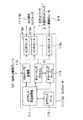
IPアドレス設定処理部111は、8つの機能を有する。この機能群は、エッジルータ11がネットワークの設定の起点となる側すなわち入力側になる場合の機能と、エッジルータ11Bが基点となるエッジルータ11Aから見て相手側すなわち出力側になる場合の機能を含む。ここで図6はこの機能群の関連を説明する図である。図6において、左側に記述された機能は、入力側のエッジルータ11Aとしての動作時に利用され、右側に記述された機能は、出力側のエッジルータ11Bとしての動作時に利用されるものである。
The IP address
第1の機能F1は、入力側のエッジルータ11Aのインタフェース116aに設定するIPアドレスをIPアドレスプール112の中から選択する機能である。第2の機能F2は、第1の機能F1によって選択したIPアドレスを出力側のエッジルータ11Bに通知するためにRSVP−TE処理部113へ通知する機能である。第1及び第2の機能は、光パスPを確立するためのPathメッセージを送信するときに用いられる。
The first function F1 is a function for selecting an IP address to be set to the
第3の機能F3から第6の機能F6までは、エッジルータ11Bが出力側としてPathメッセージを受け取ってからResvメッセージを送り返す場面で用いられる機能である。
第3の機能F3は、Pathメッセージ受信時に、RSVP−TE処理部113から入力側のエッジルータ11Aのインタフェースに設定するIPアドレスとサブネットマスクを受信する機能である。
The third function F3 to the sixth function F6 are functions used when the
The third function F3 is a function of receiving the IP address and subnet mask set in the interface of the
第4の機能F4は、第3の機能F3で受け取った入力側のエッジルータ11AのIPアドレスが属するサブネット(IPアドレスの集合)の中から入力側のエッジルータ11Aが使用していないものを選択する機能である。
The fourth function F4 selects the subnet (set of IP addresses) to which the IP address of the input
第5の機能F5は、第4の機能F4によって選択したIPアドレスを出力側のインタフェースに設定するIPアドレスとし、RSVP−TE処理部113から通知されたIPアドレスを入力側エッジルータ11Aのインタフェースに設定したIPアドレスへのルーチング情報としてインタフェース116に設定する機能である。これにより、選択したIPアドレスがIPルーチングプロトコル114に通知されるとともに、IPルーチングテーブル115に反映する。
The fifth function F5 uses the IP address selected by the fourth function F4 as the IP address to be set in the output side interface, and uses the IP address notified from the RSVP-
第6の機能F6は、選択したIPアドレスを入力側のエッジルータ11Aに通知するためにRSVP−TE処理部113へ通知する機能であり、RSVP−TE処理部113からResvメッセージが入力側のエッジルータ11Aに送られることになる。第6の機能F6までが終了すると、再びメッセージを受け取った入力側のエッジルータ11Aに処理が移る。
The sixth function F6 is a function for notifying the selected IP address to the RSVP-
第7の機能F7は、入力側のエッジルータ11Aで、出力側のエッジルータ11Bから来る光パスP確立を知らせるResvメッセージ受信時に、RSVP−TE処理部113から同時に送られてきた出力側のエッジルータ11BのIPアドレスとサブネットマスクを受信する機能である。
The seventh function F7 is that the input-
第8の機能F8は、Pathメッセージ送信時に入力側のエッジルータ11A自身が選択したIPアドレスを入力側のエッジルータのインタフェースに設定するIPアドレスとし、RSVP−TE処理部113から受信したIPアドレスを出力側のエッジルータ11Bのインタフェースに設定されたIPアドレスへのルーチング情報としてインタフェース116に設定する機能である。これにより、出力側が選択したIPアドレスが入力側のIPルーチングプロトコル114に通知されるとともに、IPルーチングテーブル115にも反映される。この機能まで問題なく終了した後は、新規設定された光パスPがIPネットワークの一部として稼動する。1回目のネゴシエーションが失敗した場合には、再度のネゴシエーションが必要になる。
The eighth function F8 uses the IP address selected by the input-
IPアドレスプール112は、エッジルータ11が使用可能なIPアドレスを保持するデータベースである。ここに管理しているIPアドレスを用いればIPアドレスの重複割り当ての心配がない。IPアドレスプール112によって管理されているアドレスは、各エッジルータ11のレベルでサブネットのまとまりをつけて個別に管理することもできるが、DHCPサーバと同様のものを立ち上げることで各エッジルータ11のIPアドレスプール112を同一の内容に保持することもできる。その他、複数のインタフェースに同一のアドレスを割り付けてしまわない程度の管理ができる管理方法をとれば本発明のためのIPアドレスプール112には十分であり、ここに記述した方法に限られない。
The
RSVP−TE処理部113は、光パス確立のためのGMLPS拡張されたRSVP−TEシグナリングプロトコルに拡張オブジェクトを付加したものを動作させるための部分である。このシグナリングプロトコルで入力側のエッジルータ11AからPathのシグナルを出せば、それに従って経路上の一つ一つの光クロスコネクトを設定しながら出力側のエッジルータ11Bまで光パスPを確立していく。そして、同一経路を通りながらResvのシグナルが入力側のエッジルータ11Aに戻っていき、光パスPが確立する。これに加え、本実施形態におけるRSVP−TE処理部113はIPアドレス設定処理部111から通知されたIPアドレスとサブネットマスクを拡張オブジェクトに記載して相手側のエッジルータ11に通知する機能、及び、相手側のエッジルータ11から拡張オブジェクトに記載して通知されたIPアドレスとサブネットマスクを受信する機能を有する。この機能拡張は、従来からのRSVP−TEのシグナリングプロトコルを損なわずに、同一プロトコルの無理のない拡張によって実現されている。なお、RSVP−TE処理部113が送受信する光パス確立のための信号は、GMPLS制御プレーン107を経由するもので、通常のデータ通信とは異なるプレーンからのシグナリングによって光ネットワークとIPネットワーク双方の設定を行っている。また、このRSVP−TE処理部113は、「光パスを確立する手段」に相当する。
The RSVP-
IPルーチングプロトコル114は、OSPF(Open Shortest Path Fast)などの一般的なIPルーチングプロトコルを動作させて、IPルーチングテーブル115を生成するという通常の機能に加え、IPアドレス設定処理部111から通知されたIPアドレスをOSPFなどの一般的なIPルーチングプロトコルで他のルータに伝達する機能を有する。なお、ここでの一般的なIPルーチングプロトコルとは、一般的なIPネットワークにおけるルート制御を行うプロトコルをさしており、単純に静的なルートを設定するだけのものやOSPF以外にルーチング情報の相互交換を通して経路制御するRIP(Routing Information Protocol)などによって動的にIPネットワークでのルーチングを決定するものをも含むことができる。
本発明の利点を十分に活用するためには、新規に確立したパス情報を反映して、最短経路になるようなルーチングを自動的に見つける機構を持つOSPFが稼動していることが望ましい。
The
In order to fully utilize the advantages of the present invention, it is desirable that an OSPF having a mechanism that automatically finds a routing that is the shortest path reflecting newly established path information is operating.
なお、OSPFは、例えば「RFC2328-OSPF Version 2」、IETF、[online]、1998年4月掲載、[2004年8月検索]、インターネット http://www.ietf.org/rfc/rfc2328.txtに記載されている。
For example, OSPF is “RFC2328-
IPルーチングテーブル115は、IPルーチングプロトコル114によって生成される通常のIPルーチングテーブルを格納する部分であるが、IPアドレス設定処理部111から通知されたIPアドレスをIPルーチングテーブル115に自動的に反映させる機能も有する。
The IP routing table 115 is a part for storing a normal IP routing table generated by the
インタフェース116は、エッジルータ11の物理インタフェースであり、IPパケットの転送に用いられるほか、IPルーチングプロトコル114の制御パケットの送受信にも利用される。エッジルータ11のインタフェースには、光ネットワーク1側に向いているインタフェース116a、116b…と、外部IPネットワーク2側に向いているインタフェース116xがあり、光ネットワーク1側に向いているものは相手側のエッジルータ11Bと光パスPを介して直接IP通信が可能であり、外部IPネットワーク2側に向いているものは外部IPネットワーク2内の隣接IPルータ216と直接IP通信を行う。このうち、本実施形態でIPアドレスの設定の対象となるのは光ネットワーク1側に向いているインタフェース116a、116b…だけであり、外部IPネットワーク2側向いているインタフェース116xは、この外部IPネットワーク2と通信できるようなIPアドレスを予め固定的に割り当てられている。
The interface 116 is a physical interface of the
[IPアドレス設定方法]
次に、前記説明した光ネットワーク1におけるIPアドレス設定方法の手順について、図3に沿って説明する(図1、図2を適宜参照)。図3は、光パスP設定の際のIPアドレス設定手順の具体例を示すシーケンス図である。この図3において、光パスPは通常両方向のパスであるため、通信方向によって入力側・出力側の区別はないが、ここでは光パスPを確立するためのシグナリングメッセージを最初に送出する側を入力側のエッジルータ11A、その相手となるエッジルータ11を出力側のエッジルータ11Bと呼ぶこととする。
[IP address setting method]
Next, the procedure of the IP address setting method in the
まず、光パスPを確立するシグナリングを送出する前に、入力側のエッジルータ11AはIPアドレスプール112から30ビットマスクのサブネットマスクとして未使用のIPアドレスの集まり(サブネット)を選択する(S1)。ここでは、100.1.1.0/30のサブネット、すなわちサブネットマスクが30ビットで100.1.1.0から100.1.1.3までの4つのIPアドレスの集合を選択したとする。そのサブネットに含まれる有効なIPアドレスである100.1.1.1から100.1.1.2のうちの一つを選択して入力側のエッジルータ11Aのインタフェースに設定するIPアドレスとする。ここでは、100.1.1.1/30を選択したとする。
First, before sending signaling for establishing the optical path P, the
次に、光パスPを確立するためにGMPLSのPathメッセージを送出する(S2)が、そのメッセージには通常の制御情報に加えて図4に示す拡張オブジェクト300を記載する。拡張オブジェクトは、拡張オブジェクトの型301、拡張オブジェクトの長さ302、入力側のエッジルータ11Aが選択したIPアドレス303及びそのサブネットマスク304を含む。
Next, a GMPLS Path message is sent to establish the optical path P (S2). In this message, the extended object 300 shown in FIG. 4 is described in addition to the normal control information. The extension object includes an
Pathメッセージを受信した光クロスコネクト12は、Pathメッセージの内容を解析してGMPLSで規定される通常の光パス設定動作を行うが、拡張オブジェクト300については無視し、一切内容を変えないまま次の光クロスコネクト12に転送する。
The
出力側のエッジルータ11BがPathメッセージを受信したら(S3)、GMPLSで規定される光パス設定動作に加えて、後記のように出力側のエッジルータ11Bの光ネットワーク向きのインタフェースにIPアドレスを設定する動作を行う(S4)。
まず、入力側のエッジルータ11AがPathメッセージに格納した拡張オブジェクト300を取り出し、IPアドレス303とサブネットマスク304を参照する。IPアドレス303は入力側のエッジルータ11Aが利用するIPアドレスであるので、それ以外のIPアドレスをサブネットの中から選択する。ここでは、残り1つである100.1.1.2/30を選択したとする。次に、先ほど選択したIPアドレス(100.1.1.2/30)を出力側のエッジルータ11Bのインタフェースに設定するIPアドレスとして、光パスPを確立する光ネットワークの出力側のエッジルータ11B物理インタフェースに設定し、拡張オブジェクト300に記載されていた入力側のエッジルータ11AのIPアドレス(100.1.1.1/30)を入力側のIPアドレスとしてルーチングプロトコルに通知する。
When the output
First, the
インタフェースの設定が終了したら、出力側のエッジルータ11BはResvメッセージを入力側のエッジルータ11Aに向けて送信する(S5)。このResvメッセージには、出力側IPアドレスとサブネットマスク(100.1.1.2/30)を記載した拡張オブジェクト300を格納する。
When the interface setting is completed, the
Pathメッセージのときと同様に、途中経路に存在する光クロスコネクト12は、通常の光パス設定動作を行い、拡張オブジェクト300は内容を変更しないまま次の光クロスコネクトに転送する。
入力側のエッジルータ11AがResvメッセージを受信したら(S6)、ステップSlで選択したIPアドレス(100.1.1.1/30)を入力側のエッジルータのインタフェースに設定するIPアドレスとして、受信したResvメッセージの拡張オブジェクト300に格納されているIPアドレス303を相手側のIPアドレスとして光パスPを確立する入力側のエッジルータ11Aの物理インタフェースについてのルーチングプロトコルを設定する(S7)。
As in the case of the Path message, the
When the
前記の手順により、光パスPの確立と同時に、入力側のエッジルータ11Aと出力側のエッジルータ11Bのインタフェースに、同一サブネットのIPアドレスを付与することができる。なお、サブネットマスクで限定したサブネットの大きさを小さくし過ぎたなどの理由で、出力側のエッジルータ11Bで有効なIPアドレスの候補がなかった場合には、Resvによってそのことを入力側のエッジルータ11Aに通知し、サブネットマスクを変更して候補の幅を広げたり、入力側のエッジルータ11AのIPアドレスを変更したりした後に、再度同様のネゴシエーションを行えば問題は解決する。
By the above procedure, simultaneously with the establishment of the optical path P, the IP addresses of the same subnet can be assigned to the interfaces of the input
本実施形態では、Pathメッセージに付加した拡張オブジェクトに格納した情報は、入力側のエッジルータ11Aのインタフェースに割り当てたIPアドレスとサブネットマスクの情報であり、Resvメッセージに付加した拡張オブジェクトに格納した情報は、出力側のエッジルータ11Bに割り当てたIPアドレスとサブネットマスクであった。本実施形態では、Pathメッセージに付加した入力側のエッジルータ11Aの情報があれば、同一のサブネットのIPアドレスから出力側のエッジルータ11BのためのIPアドレスを決定できるので十分であったが、このような情報以外でも目的を達成することができる。すなわち、エッジルータ11Aと11B間でIPアドレス選択のネゴシエーションを行えるような適切な候補に関する情報を送れば、本発明での目的は達成しうる。例えば、Pathメッセージに付加する情報として、最初から入力側で出力側のIPアドレスの候補をサブネットマスク情報とともに送るというのも可能な選択肢である。ただし、この場合には、出力側IPアドレスから入力側IPアドレスがわかるように必ず入力側IPアドレスと出力側IPアドレスが連続しているといったルールを決めておく必要がある。具体的には、入力側IPアドレスが100.1.1.1に対して出力側で100.1.1.2になるようにしておけば、一方のIPアドレスから相手のIPアドレスがわかる。
In the present embodiment, the information stored in the extended object added to the Path message is information on the IP address and subnet mask assigned to the interface of the
同様に、出力側で利用可能な連続したIPアドレスの最初と最後を入力側から送ることにしておいて、入力側から送ったIPアドレスから入力側IPアドレスがわかるようにしておいて、サブネットマスクを固定するようにしておくこともできる。
本発明におけるネゴシエーションで用いる情報は候補を選択するための情報であればどのようなものでもよく、IPアドレスとサブネットマスクに限定するものではない。
Similarly, the first and last consecutive IP addresses available on the output side are sent from the input side, the IP address sent from the input side is known, and the IP address of the input side is known. Can also be fixed.
The information used in the negotiation in the present invention may be any information as long as it is information for selecting a candidate, and is not limited to the IP address and the subnet mask.
また、本実施形態では、IPアドレスとしてIPv4のアドレスを扱っているが、図4を参照して、拡張オブジェクトの型301を1ではなく、IPv6に対応した2に変更し、拡張オブジェクトの長さ302を12ではなく、IPv6に必要な領域が確保できる36に変更するなどすれば、本発明を容易にIPv6にも対応させることができ、適用範囲はIPv4に限定されるものではない。
In this embodiment, an IPv4 address is handled as an IP address. However, referring to FIG. 4, the
図5は、図1を補足説明するための図である。図1においては、RSVP−TEシグナリングSが、光ネットワークの物理レイヤを通過していることが記述されているが、このシグナリングがGMPLS制御プレーンを利用していることを図5は示している。この図に示すように、GMPLS制御プレーンにおいて、Pathメッセージの通過する光クロスコネクト12などに設定を行っている。そして、Resvメッセージはやはり同じ経路でGMPLS制御プレーンを通過している。
FIG. 5 is a diagram for supplementarily explaining FIG. In FIG. 1, it is described that the RSVP-TE signaling S passes through the physical layer of the optical network, but FIG. 5 shows that this signaling uses the GMPLS control plane. As shown in this figure, in the GMPLS control plane, settings are made for the
図6は図2を補足するためのもので、図2において記述されているIPアドレス設定処理部111の各機能のつながりを示している。この図において、機能F1、F2、F7、F8が入力側のエッジルータ11Aとして必要とされる機能であり、F3、F4、F5、F6は出力側のエッジルータ11Bとして要求される機能である。
FIG. 6 is a supplement to FIG. 2 and shows the connection of each function of the IP address
以上のように、本実施形態によれば、光パス確立の際に自動的にネゴシエーションが行われ、物理レイヤ(光レイヤ)だけでなくIPレイヤにおいても入力側及び出力側のエッジルータ11のIPアドレスを自動的に付与することができる。
IPネットワークのトラヒック量をトリガーとして光パスを確立するなど、あらかじめ光パスを確立する相手先エッジルータ11を特定できない場合でも人手を介することなくIPアドレスやルーチングの設定まで行うことができるようになり、IPネットワークの状況に応じて動的に光パスの帯域やトポロジを変更することなども含めて、従来よりも頻繁かつ柔軟に光パスを制御することができるようになる。これにより、利用状況に即応した光パスの設定と運用が可能となるため、光リソースの効率的な利用ができるようになり、光ネットワークを提供するキャリアにとっては、最終的には設備コストの削減を達成できる。
As described above, according to the present embodiment, the negotiation is automatically performed when the optical path is established, and the IP of the
Even when the
さらに、本実施形態を実現する際には、既存のGMPLSシグナリングにIPアドレスとサブネットマスクの情報を記載する付加的なオブジェクトを付け加えるだけで基本的な部分を実施することができるので、相手側のエッジルータ11にIPアドレスとサブネットマスクの情報を伝達するための特別なプロトコルを開発するコストを削減できるという利点もある。
Furthermore, when implementing this embodiment, the basic part can be implemented simply by adding an additional object describing the IP address and subnet mask information to the existing GMPLS signaling. There is also an advantage that the cost for developing a special protocol for transmitting the IP address and subnet mask information to the
1 光ネットワーク
2 外部IPネットワーク
S RSVP−TEシグナリング
P 光パス
11 エッジルータ
11A 入力側のエッジルータ
11B 出力側のエッジルータ
12 光クロスコネクト(OXC)
107 GMPLS制御プレーン
111 IPアドレス設定処理部
112 IPアドレスプール
113 RSVP−TE処理部
114 IPルーチングプロトコル
115 IPルーチングテーブル
116 インタフェース
116a 光ネットワーク側インタフェース
116b 光ネットワーク側インタフェース
116x 外部IPネットワーク側インタフェース
216 隣接IPルータ
300 拡張オブジェクト
301 拡張オブジェクトの型(Type)
302 拡張オブジェクトの長さ(Length)
303 IPアドレス
304 サブネットマスク
DESCRIPTION OF
107
302 Length of extended object (Length)
303 IP address 304 Subnet mask
Claims (7)
前記第1のルータは、利用可能なIPアドレスを記憶した記憶手段を参照して前記第2のルータがインタフェースに設定すべきIPアドレスの候補を作成する手段と、この作成した候補を前記第2のルータに通知する手段を備えて、前記候補を作成して前記第2のルータに通知し、
前記第2のルータは、前記通知された候補を受信する手段と、この受信した候補から未使用のIPアドレスを選択する手段と、この選択したIPアドレスを前記第1のルータに通知する手段を備え、前記候補から未使用のIPアドレスを選択してこれを前記第1のルータに通知し、
前記両ルータがそれぞれのインタフェースにIPアドレスを設定すること
を特徴とするIPアドレス設定方法。 In an optical network system having a plurality of devices that provide an optical path and connected to a plurality of IP networks, a new one is provided between a first router and a second router as devices constituting the optical network. When establishing an optical path connected to the IP network, the first router and the second router negotiate so that both routers set an IP address for each interface. ,
The first router refers to a storage unit that stores available IP addresses, generates a candidate for an IP address that the second router should set for an interface, and sets the generated candidate as the second Means for notifying the second router, creating the candidate and notifying the second router,
The second router includes means for receiving the notified candidate, means for selecting an unused IP address from the received candidate, and means for notifying the first router of the selected IP address. And selecting an unused IP address from the candidates and notifying the first router of this,
An IP address setting method, wherein both the routers set an IP address for each interface.
前記第2のルータは、前記通知されたIPアドレス以外のIPアドレスを前記通知されたサブネットマスクに含まれるIPアドレスから自己のインタフェースに設定するために選択すること
を特徴とする請求項1に記載のIPアドレス設定方法。 The first router notifies the second router of the subnet mask as the candidate and the IP address set by the first router on its own interface;
The second router selects an IP address other than the notified IP address from the IP address included in the notified subnet mask to set to its own interface. IP address setting method.
前記第1のルータは、前記候補を、前記GMPLSのシグナリング機能における拡張オブジェクトを用いて前記第2のルータへと通知すること
を特徴とする請求項1又は請求項2に記載のIPアドレス設定方法。 The first router and the second router are routers that implement GMPLS, which is a technology for controlling an optical network,
3. The IP address setting method according to claim 1, wherein the first router notifies the candidate to the second router using an extension object in the signaling function of the GMPLS. .
前記ルータは、前記他のルータとの間に前記IPネットワークに繋がる光パスを確立する手段と、
利用可能なIPアドレスを記憶した記憶手段と、
前記記憶手段を参照して前記他のルータがインタフェースに設定すべきIPアドレスの候補を作成する手段と、
前記作成した候補を前記他のルータに通知する手段と、
前記通知された候補からIPアドレスを自己のインタフェースに設定するために選択する手段及び前記選択したIPアドレスを前記候補を通知したルータに通知する手段を備えた前記他のルータから、IPアドレスを選択した旨の通知を受信する手段と
を備えたことを特徴とするルータ。 A router that is used in an optical network connected to a plurality of IP networks, and that establishes an IP address on an interface by negotiating with the other router when establishing an optical path with the other router,
The router establishes an optical path connected to the IP network with the other router;
Storage means for storing available IP addresses;
Means for creating an IP address candidate to be set as an interface by the other router with reference to the storage means;
Means for notifying the created candidate to the other router;
Select an IP address from the other router comprising means for selecting an IP address from the notified candidate to set to its own interface and means for notifying the selected IP address to the router that has notified the candidate And a means for receiving a notification to the effect.
前記通知を受信する手段と、
前記通知された候補からIPアドレスを自己のインタフェースに設定するために選択する手段と、
前記選択したIPアドレスを前記候補を送信したルータに通知する手段と
をさらに備えたことを特徴とする請求項4に記載のルータ。 As a configuration when the router is notified of the candidate,
Means for receiving the notification;
Means for selecting an IP address from the notified candidates to set to its own interface;
The router according to claim 4, further comprising means for notifying the selected IP address to the router that has transmitted the candidate.
前記候補としてサブネットマスクと前記第1のルータが自己のインタフェースに設定したIPアドレスを前記第2のルータへと通知し、
前記第2のルータとして前記候補を通知される場合に、
前記通知されたIPアドレス以外のIPアドレスを前記通知された候補に含まれるIPアドレスから自己のインタフェースに設定するために選択することを特徴とする請求項5に記載のルータ。 When the router notifies the candidate as the first router,
Notifying the second router of the subnet mask and the IP address set by the first router on its own interface as the candidate,
When the candidate is notified as the second router,
The router according to claim 5, wherein an IP address other than the notified IP address is selected from the IP addresses included in the notified candidate for setting to its own interface.
前記第1のルータとして前記候補を通知する場合に、前記候補を、前記GMPLSのシグナリング機能における拡張オブジェクトを用いて前記第2のルータへと通知すること
を特徴とする請求項6に記載のルータ。 The router is a router equipped with GMPLS, which is a technology for controlling an optical network,
The router according to claim 6, wherein when the candidate is notified as the first router, the candidate is notified to the second router using an extension object in the signaling function of the GMPLS. .
Priority Applications (1)
| Application Number | Priority Date | Filing Date | Title |
|---|---|---|---|
| JP2004240507A JP4144802B2 (en) | 2004-08-20 | 2004-08-20 | IP address setting method and router |
Applications Claiming Priority (1)
| Application Number | Priority Date | Filing Date | Title |
|---|---|---|---|
| JP2004240507A JP4144802B2 (en) | 2004-08-20 | 2004-08-20 | IP address setting method and router |
Publications (2)
| Publication Number | Publication Date |
|---|---|
| JP2006060536A JP2006060536A (en) | 2006-03-02 |
| JP4144802B2 true JP4144802B2 (en) | 2008-09-03 |
Family
ID=36107650
Family Applications (1)
| Application Number | Title | Priority Date | Filing Date |
|---|---|---|---|
| JP2004240507A Expired - Fee Related JP4144802B2 (en) | 2004-08-20 | 2004-08-20 | IP address setting method and router |
Country Status (1)
| Country | Link |
|---|---|
| JP (1) | JP4144802B2 (en) |
Families Citing this family (3)
| Publication number | Priority date | Publication date | Assignee | Title |
|---|---|---|---|---|
| WO2012051078A1 (en) * | 2010-10-15 | 2012-04-19 | Marvell World Trade Ltd. | Assignment of network addresses |
| JP2012199723A (en) * | 2011-03-18 | 2012-10-18 | Kddi Corp | Addresses allocation method in system having connected plural resource management devices, resource management device, and program |
| JP2013247451A (en) * | 2012-05-24 | 2013-12-09 | Nec Corp | Router and control method thereof |
-
2004
- 2004-08-20 JP JP2004240507A patent/JP4144802B2/en not_active Expired - Fee Related
Also Published As
| Publication number | Publication date |
|---|---|
| JP2006060536A (en) | 2006-03-02 |
Similar Documents
| Publication | Publication Date | Title |
|---|---|---|
| US10250459B2 (en) | Bandwidth on-demand services in multiple layer networks | |
| US9794192B2 (en) | Method and device for allocating packet switching resource | |
| JP4374307B2 (en) | Label switch path routing control method | |
| JP6203943B2 (en) | Method and apparatus for accessing device network | |
| EP2528298B1 (en) | Method, device for implementing identifier and locator split, and method for data encapsulating | |
| EP3043519B1 (en) | Method, controller, forwarding device, and network system for forwarding packets | |
| WO2019007166A1 (en) | Method and apparatus for determining identification information about cross-domain path, and storage medium | |
| US8295204B2 (en) | Method and system for dynamic assignment of network addresses in a communications network | |
| JP3808495B2 (en) | GMPLS + IP / MPLS node and IP / MPLS node | |
| JP2003069619A (en) | Route changing method for label transfer network, label switching node, and management node | |
| CN110650090B (en) | Routing method and router | |
| JP2001189751A (en) | System, element and method for supporting virtual private network of label exchange communication network | |
| US20090103533A1 (en) | Method, system and node apparatus for establishing identifier mapping relationship | |
| EP1753176A1 (en) | A method for realizing route transmitting in the network | |
| EP3979599B1 (en) | Computing segment identifier lists for multipaths in a segment routing-enabled network | |
| JP2003032280A (en) | Assignment system of link identifier in connection-type communication network | |
| US8694673B2 (en) | Systems and methods for host identification | |
| JP2006262293A (en) | Transmission apparatus and free label search method | |
| US8902909B2 (en) | Method, system, and device for implementing service forwarding | |
| JP2009519666A (en) | Resource sharing between network and tunnel | |
| EP1775892A1 (en) | Mobile communication access system, packet transfer device, and path re-establishing method | |
| JP2004159112A (en) | Communication control system, communication control method, and routing controller and router device suitably used for them | |
| EP3493492A1 (en) | Rsvp make-before-break label reuse | |
| US10341228B1 (en) | RSVP make-before-break label reuse | |
| WO2012149777A1 (en) | Method, apparatus, and system for establishing label-switched path |
Legal Events
| Date | Code | Title | Description |
|---|---|---|---|
| A621 | Written request for application examination |
Free format text: JAPANESE INTERMEDIATE CODE: A621 Effective date: 20060719 |
|
| A977 | Report on retrieval |
Free format text: JAPANESE INTERMEDIATE CODE: A971007 Effective date: 20080605 |
|
| TRDD | Decision of grant or rejection written | ||
| A01 | Written decision to grant a patent or to grant a registration (utility model) |
Free format text: JAPANESE INTERMEDIATE CODE: A01 Effective date: 20080610 |
|
| A01 | Written decision to grant a patent or to grant a registration (utility model) |
Free format text: JAPANESE INTERMEDIATE CODE: A01 |
|
| RD01 | Notification of change of attorney |
Free format text: JAPANESE INTERMEDIATE CODE: A7426 Effective date: 20080613 |
|
| A61 | First payment of annual fees (during grant procedure) |
Free format text: JAPANESE INTERMEDIATE CODE: A61 Effective date: 20080613 |
|
| R150 | Certificate of patent or registration of utility model |
Free format text: JAPANESE INTERMEDIATE CODE: R150 Ref document number: 4144802 Country of ref document: JP Free format text: JAPANESE INTERMEDIATE CODE: R150 |
|
| FPAY | Renewal fee payment (event date is renewal date of database) |
Free format text: PAYMENT UNTIL: 20110627 Year of fee payment: 3 |
|
| FPAY | Renewal fee payment (event date is renewal date of database) |
Free format text: PAYMENT UNTIL: 20120627 Year of fee payment: 4 |
|
| FPAY | Renewal fee payment (event date is renewal date of database) |
Free format text: PAYMENT UNTIL: 20130627 Year of fee payment: 5 |
|
| FPAY | Renewal fee payment (event date is renewal date of database) |
Free format text: PAYMENT UNTIL: 20140627 Year of fee payment: 6 |
|
| S531 | Written request for registration of change of domicile |
Free format text: JAPANESE INTERMEDIATE CODE: R313531 |
|
| R350 | Written notification of registration of transfer |
Free format text: JAPANESE INTERMEDIATE CODE: R350 |
|
| LAPS | Cancellation because of no payment of annual fees |