JP4144087B2 - Imaging device - Google Patents
Imaging device Download PDFInfo
- Publication number
- JP4144087B2 JP4144087B2 JP36333998A JP36333998A JP4144087B2 JP 4144087 B2 JP4144087 B2 JP 4144087B2 JP 36333998 A JP36333998 A JP 36333998A JP 36333998 A JP36333998 A JP 36333998A JP 4144087 B2 JP4144087 B2 JP 4144087B2
- Authority
- JP
- Japan
- Prior art keywords
- memory
- storage unit
- housing
- memory storage
- recess
- Prior art date
- Legal status (The legal status is an assumption and is not a legal conclusion. Google has not performed a legal analysis and makes no representation as to the accuracy of the status listed.)
- Expired - Fee Related
Links
Images


Description
【0001】
【発明の属する技術分野】
本発明は撮像装置に関し、特に、被写体の動画像を撮像して記録媒体に記録するとともに、前記被写体の静止画像を半導体メモリに記録する撮像装置に関する。
【0002】
【従来の技術】
ビデオカメラ等の撮像装置においては、従来は、被写体からの光画像をCCD(Charge Coupled Device)等の撮像素子によって映像信号に変換して記録媒体であるビデオテープ等に記録するものが主流であった。
【0003】
しかし、近年では、パーソナルコンピュータの家庭への浸透に伴って、ビデオカメラによって撮像した画像(動画像または静止画像)をパーソナルコンピュータ等に取り込むことへのニーズが増大してきた。そこで、撮像した画像を、ビデオテープに記録するだけでなく、着脱可能な半導体メモリ等に記憶させ、この半導体メモリを介してパーソナルコンピュータに画像データを取り込むことができるビデオカメラも出現しつつある。
【0004】
【発明が解決しようとする課題】
ところで、近年のビデオカメラ等の撮像装置は、実装技術や画像処理技術の進歩に伴って装置のサイズが非常に小型化されているため、上述のような半導体メモリを配置するスペースを確保することが困難になっている。
【0005】
一般的な方法としては、ビデオカメラの本体内部に半導体メモリを内蔵させる方法が考えられるが、このような方法ではユーザがその製品を初めて手にした場合に、半導体メモリがどこに格納されているかを理解するのに時間を要するという問題点があった。
【0006】
また、本体内部に内蔵した場合には、半導体メモリを外部から視覚的に確認することが困難であるので、何らかの補助的手段を設けない限りは、半導体メモリが装着されているか否かを容易に判断することが困難であるという問題点もあった。
【0007】
更に、半導体メモリを内蔵する場所によっては、他の部品や部材との関係から、装置の小型化の阻害要因になる場合があるという問題点もあった。
本発明はこのような点に鑑みてなされたものであり、半導体メモリの装着位置と装着状況を容易に確認することができるとともに、装置の小型化を阻害することなく半導体メモリを装備することを可能とする撮像装置を提供することを目的とする。
【0008】
【課題を解決するための手段】
本発明では上記課題を解決するために、所定の厚みを有する矩形の筐体と、筐体の前部に設けられた光学系を内蔵する鏡筒部と、筐体の後部に設けられたビューファインダとを有し、ビューファインダを正面に見て筐体の右側面が所定の膨らみを有するように形成された装置本体と、筐体の右側面に開口され、被写体からの光画像を動画像または静止画像として記録する記録媒体が装着される装着部と、筐体の右側面に対応して所定の膨らみを有するように形成され、装着部を覆う蓋部と、蓋部に設けられ、被写体からの光画像を動画像または静止画像として記録する半導体メモリを着脱可能に収納すると共に、半導体メモリの着脱を確認するための窓を有する収納部と、を備えることを特徴とする撮像装置が提供される。
【0009】
ここで、記録媒体が装着される装着部を覆う蓋部に対して、半導体メモリを着脱可能に収納する収納部を設けるようにしたので、メモリの収納位置と、メモリの収納状態がユーザに理解しやすくなる。
【0010】
【発明の実施の形態】
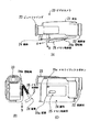
以下、本発明の実施の形態を図面を参照して説明する。図1は、本発明の実施の形態の構成例を示す外観図である。
【0011】
図1(A)に示すように、本発明に係るビデオカメラ20は、回路基板等が内蔵された本体21、光学系が内蔵された鏡筒部22、被写体の撮像状況を確認するためのビューファインダ23、ビデオテープが装着される装着部を覆う蓋部24、蓋部24の一部に設けられ、半導体メモリ(以下、単にメモリという)を収納するメモリ収納部25等によって構成されている。
【0012】
蓋部24は、図1(B)に示すように、本体21と回転軸24aを介して接続されており、この回転軸24aを中心として矢印Cの方向に開閉可能とされている。蓋部24が開かれた状態においては、矢印Dの方向にビデオテープを取り出すことができる。
【0013】
メモリ収納部25は、図1(A)に示すように、蓋部22に対して回転軸25bを介して接続されており、この回転軸25bを中心として矢印Bの方向に開閉可能とされている。メモリ収納部25が開かれた状態においては、矢印Aの方向にメモリを取り出すことができる。
【0014】
なお、本実施の形態において用いられているメモリは、ガム型のメモリとされており、その一部に設けられた端子を介して本体21との間でデータを授受することが可能である。
【0015】
図1(C)に示すように、メモリ収納部25の一部には、アクリル等の透明部材によって形成された窓部25aが設けられているので、ユーザは、メモリが装着されているか否かをこの窓部25aを通じて確認することができる。
【0016】
メモリ収納部25の左上部には、メモリイジェクトボタン25cが具備されており、図1(A)に示すように、メモリ格納部25が開かれた状態において、このメモリイジェクトボタン25cが操作されると、メモリの一部が突出するので、その部分を把持することによりメモリを容易に取り出すことができる。
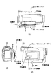
【0017】
図2は、図1に示すメモリ収納部25の詳細な構成例を示す断面図である。図2(A)に示すように、メモリ収納部25は、メモリホルダ40、ポップアップバネ42、および、本体側端子43等によって構成されている。
【0018】
メモリホルダ40は、ガム型のメモリ30が挿入され、これを保持するための筒状形状を有している。
メモリホルダ40の内部には、メモリ30が装着された場合に、メモリ30の端部に設けられているメモリ側端子30aと接触してデータを授受するための本体側端子43が設けられている。
【0019】
以上のようなメモリ収納部25は、回転軸25bによって蓋部25の一部に形成された凹部24bに対して回転軸25bを介して係止されている。
ポップアップバネ42は、メモリ収納部25に対して図の下向きの力を印加し、ロックアーム45が操作されてロックが解除された場合には、メモリ収納部25を凹部24bから外側へ押し出す働きを有する。
【0020】
ロックアーム45は、図の左右方向にスライド可能であり、ロック爪45aがメモリ収納部25の上部側面に設けられたロックピン(後述する)と係合することにより、メモリ収納部25が開かないようにロックする。
【0021】
ロックバネ45bは、復元力によりロックアームを図の左側に向けて押圧し、ロック爪45aによりロックピンをロックさせる。
位置検出スイッチ46は、メモリ収納部25が凹部24bに収納されたことを検知するためのスイッチである。
【0022】
図2(B)は、メモリ30がメモリ収納部25に収納された状態を示す断面図である。この図に示すように、メモリ収納部25にメモリ30が収納されると、メモリ側端子30aに本体側端子43が接触する。本体側端子43は、図示せぬフレキシブル基板によって本体内の回路基板と接続されているので、これらの間でデータの授受が可能となる。
【0023】
図3(A)は、メモリ30が収納されたメモリ収納部25が、蓋部24の凹部24bに格納された場合の様子を示す断面図である。
この図に示すように、メモリ収納部25は凹部24b内にその全体が収容されるので、蓋部24に対する操作の障害となることはない。
【0024】
メモリ収納部25が凹部24b内に格納されると位置検出スイッチ46のトグル部が押圧されるので、位置検出スイッチ46の状態を監視することにより、メモリ収納部25が凹部24bに確実に格納されたか否かを知ることができる。
【0025】
図3(B)は、図3(A)の状態におけるロックアーム45の状態を示す図である。この図に示すように、ロックアーム45はロックバネ45bによって図の左方向への力を受けているので、ロック爪45aはメモリ収納部25の上部側面に設けられているロックピン44と係合してメモリ収納部25が開くのを防止する。
【0026】
なお、このような状態において、ロックアーム45が図示せぬアクチュエータ等によって駆動されて図の右方向へ移動された場合には、ロックが解除され、ポップアップバネ42の復元力によって図2(B)に示すようにメモリ収納部25が開くことになる。そのような状態において、メモリイジェクトボタン25cをユーザが操作すると、メモリ30の一部がメモリ収納部25から突出して図2(A)の状態となるので、突出部分を把持することによりメモリ30を容易に取り出すことができる。
【0027】
以上に示す実施の形態によれば、ビデオテープを装着する装着部を覆う蓋部24の一部に対して凹部24bを設け、そこにメモリ収納部25を設けるようにしたので、デザイン上の理由から膨らみを有することが多い蓋部24のスペース(膨らんだ部分)を有効に利用することが可能となるので、装置の小型化を阻害することなくメモリ30を装備することが可能となる。
【0028】
また、メモリ収納部25は、透明部材による窓部25aを設けるようにしたので、メモリ30の格納位置を容易に知ることが可能となるとともに、メモリ30が装着されているか否かを簡単に確認することが可能となる。
【0029】
次に、本発明の他の実施の形態について説明する。
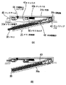
図4は、本発明に係るビデオカメラの他の構成例を示す外観図である。なお、この図において、図1に示す場合と対応する部分には同一の符号を付してあるので、その説明は適宜省略する。
【0030】
この実施の形態においては、図4(B)に示すように、蓋部24はポップアップ構造を有しており、図示せぬパンタグラフ機構により本体21の側面から所定の距離だけ突出するように構成されている。
【0031】
また、メモリ収納部25も同様にポップアップ構造とされており、蓋部24から所定の距離だけ突出するように構成されている。
なお、その他の構成は図1の場合と同様である。
【0032】
図5は、図4に示すメモリ収納部25の詳細な構成例を示す断面図である。なお、この図において、図2の場合と対応する部分には同一の符号を付してあるので、その部分の説明は適宜省略する。
【0033】
図5(A)に示すように、本実施の形態においては、板状部材60,61によって構成されるパンタグラフ機構により、メモリ収納部25が蓋部24に設けられた凹部24bから所定の距離だけ突出するように構成されている。
【0034】
板状部材61は、その一端が凹部24bの内側上部面の左隅に設けられたピン61aによって回転自在に固定されている。また、他端には図5(B)に示すように楕円孔61cが設けられており、メモリ収納部25の上部側面の右隅に設けられたピン61bがこの楕円孔61cに挿入され、板状部材61の長手方向に移動可能に固定されている。
【0035】
板状部材60も同様に、その一端が凹部24bの内側上部面の右隅に設けられたピン60aによって回転自在に固定されている。また、他端には楕円孔60cが設けられており、メモリ収納部25の上部側面の左隅に設けられたピン60bがこの楕円孔60cに挿入され、板状部材60の長手方向に移動可能に固定されている。
【0036】
板バネ62は、メモリ収納部25が凹部24bに格納されている状態において、ロックアーム45が操作された場合には、メモリ収納部25に対して図の下側へ向かう力を印加してメモリ収納部25が所定の距離だけ突出するようにする。
【0037】
以上のようなパンタグラフ機構を有するメモリ収納部25に対して、図の上方向への力(メモリ収納部25を格納する方向への力)が印加されると、板状部材60,61は、ピン60a,61aをそれぞれ回転中心として回転し、楕円孔60c,61cによってその長手方向に移動するので、あたかもパンタグラフのように動作してメモリ収納部25が凹部24bに格納される。
【0038】
図5(B)は、メモリ収納部25が凹部24bに格納された場合における、板状部材60,61の状態を示す図である。
この図に示すように、メモリ収納部25が凹部24bに格納された状態では、板状部材60,61は所定の距離だけずれを有して重ね合わされている。なお、これらの板状部材60,61は、ロックアーム45の上部に設けられており、これらは相互に干渉しないように設定されている。
【0039】
図5(B)に示す状態において、ロックアーム45が図の右側へ移動された場合には、ロック爪45aによるロックが解除されるとともに、板バネ62によって図の下側へ向かう力が印加されることにより、メモリ収納部25が凹部24bから所定の距離だけ突出され、図5(A)の状態となる。ユーザはこのような状態においてメモリイジェクトボタン25cを操作することにより、メモリ30を取り出すことが可能となる。
【0040】
なお、以上の説明では、記録媒体としてビデオテープを用いる場合を例に挙げて説明を行ったが、例えば、DVD(Digital Versatile Disk:商標)やMD(Mini Disk:商標)等を用いる場合においても、本発明を適用することが可能であることはいうまでもない。
【0041】
また、以上の実施の形態においては、メモリ収納部25に対して本体側端子43を設けてメモリ30との間でデータを授受するようにしたが、例えば、非接触式のメモリを用いるようにしてもよい。
【0042】
【発明の効果】
以上説明したように本発明では、所定の厚みを有する矩形の筐体と、筐体の前部に設けられた光学系を内蔵する鏡筒部と、筐体の後部に設けられたビューファインダとを有し、ビューファインダを正面に見て筐体の右側面が所定の膨らみを有するように形成された装置本体と、筐体の右側面に開口され、被写体からの光画像を動画像または静止画像として記録する記録媒体が装着される装着部と、筐体の右側面に対応して所定の膨らみを有するように形成され、装着部を覆う蓋部と、蓋部に設けられ、被写体からの光画像を動画像または静止画像として記録する半導体メモリを着脱可能に収納すると共に、半導体メモリの着脱を確認するための窓を有する収納部と、を備えるようにしたので、メモリの収納位置と、メモリの収納状態がユーザに理解しやすい撮像装置を提供することが可能となる。
【0043】
また、記録媒体を装着する装着部を覆う蓋部は、デザイン上の理由等によって、膨らみを有する場合が多いので、この部分のスペースを有効利用することにより、装置の小型化を阻害することなく半導体メモリを装備することが可能となる。
【図面の簡単な説明】
【図1】本発明に係るビデオカメラの実施の形態の構成例を示す図であり、(A)は上方向から眺めた図であり、(B)は後方向から眺めた図であり、(C)は横方向から眺めた図である。
【図2】図1に示すメモリ収納部の詳細な構成例を示す断面図であり、(A)はメモリの一部を挿入した状態を示し、(B)はメモリを完全に挿入した状態を示す。
【図3】図1に示すメモリ収納部の詳細な構成例を示す断面図であり、(A)はメモリ収納部を凹部に格納した状態を示し、(B)はメモリ収納部を凹部に格納した状態におけるロックアームの状態を示す。
【図4】本発明に係るビデオカメラの他の実施の形態の構成例を示す図であり、(A)は上方向から眺めた図であり、(B)は後方向から眺めた図であり、(C)は横方向から眺めた図である。
【図5】図4に示すメモリ収納部の詳細な構成例を示す断面図であり、(A)はメモリ収納部が突出した状態を示し、(B)はメモリ収納部を凹部に格納した状態にを示す。
【符号の説明】
20……ビデオカメラ,21……本体,22……鏡筒部,23……ビューファインダ,24……蓋部,24a……回転軸,25……メモリ収納部,25a……窓部,25b……回転軸,25c……メモリイジェクトボタン,30……メモリ,30a……メモリ側端子,40……メモリホルダ,42……ポップアップバネ,43……本体側端子,45……ロックアーム,45a……ロック爪,45b……ロックバネ,46……位置検出スイッチ,60,61……板状部材,60a,60b,61a,61b……ピン,60c,61c……楕円孔,62……板バネ[0001]
BACKGROUND OF THE INVENTION
The present invention relates to an imaging apparatus, and more particularly, to an imaging apparatus that captures a moving image of a subject and records it on a recording medium, and records a still image of the subject in a semiconductor memory.
[0002]
[Prior art]
Conventionally, an imaging device such as a video camera has been mainly used to convert a light image from a subject into a video signal by an imaging element such as a CCD (Charge Coupled Device) and record it on a video tape as a recording medium. It was.
[0003]
However, in recent years, with the penetration of personal computers into the home, there has been an increasing need for capturing images (moving images or still images) captured by a video camera into a personal computer or the like. In view of this, a video camera that can not only record a captured image on a video tape but also store the image in a detachable semiconductor memory or the like and capture the image data into a personal computer via the semiconductor memory is emerging.
[0004]
[Problems to be solved by the invention]
By the way, recent imaging apparatuses such as video cameras have been downsized in size with the progress of mounting technology and image processing technology, so it is necessary to secure a space for arranging the semiconductor memory as described above. Has become difficult.
[0005]
As a general method, there is a method of incorporating a semiconductor memory inside the main body of the video camera. In such a method, when the user first obtains the product, the location of the semiconductor memory is stored. There was a problem that it took time to understand.
[0006]
In addition, since it is difficult to visually confirm the semiconductor memory from the outside when it is built in the main body, it is easy to determine whether or not the semiconductor memory is mounted unless some auxiliary means is provided. There was also a problem that it was difficult to judge.
[0007]
Furthermore, depending on the location where the semiconductor memory is built, there is a problem that it may be an obstacle to downsizing of the device due to the relationship with other components and members.
The present invention has been made in view of the above points, and it is possible to easily confirm the mounting position and mounting state of the semiconductor memory and to equip the semiconductor memory without hindering the downsizing of the apparatus. An object of the present invention is to provide an imaging device that can be used.
[0008]
[Means for Solving the Problems]
In the present invention, in order to solve the above-described problem, a rectangular casing having a predetermined thickness, a lens barrel portion containing an optical system provided at the front of the casing, and a view provided at the rear of the casing A device body that is formed so that the right side of the housing has a predetermined bulge when the viewfinder is viewed in front, and an optical image from a subject that is opened on the right side of the housing. Alternatively, a mounting portion on which a recording medium to be recorded as a still image is mounted , a lid portion that is formed to have a predetermined bulge corresponding to the right side surface of the housing, and is provided on the lid portion, and is provided on the lid portion. with houses a removable semiconductor memory for recording an optical image as a moving image or a still image from the image pickup device is provided, characterized in that it and a housing portion having a window for confirming the semiconductor memory detachable Is done.
[0009]
Here, a storage unit for detachably storing the semiconductor memory is provided on the lid that covers the mounting unit on which the recording medium is mounted, so that the user understands the storage position of the memory and the storage state of the memory. It becomes easy to do.
[0010]
DETAILED DESCRIPTION OF THE INVENTION
Hereinafter, embodiments of the present invention will be described with reference to the drawings. FIG. 1 is an external view showing a configuration example of an embodiment of the present invention.
[0011]
As shown in FIG. 1A, a video camera 20 according to the present invention includes a main body 21 incorporating a circuit board and the like, a lens barrel unit 22 incorporating an optical system, and a view for confirming an imaging state of a subject. The
[0012]
As shown in FIG. 1B, the lid 24 is connected to the main body 21 via a rotating shaft 24a, and can be opened and closed in the direction of arrow C around the rotating shaft 24a. In the state where the lid portion 24 is opened, the video tape can be taken out in the direction of the arrow D.
[0013]
As shown in FIG. 1A, the memory storage portion 25 is connected to the lid portion 22 via a rotation shaft 25b, and can be opened and closed in the direction of arrow B about the rotation shaft 25b. Yes. In the state where the memory storage unit 25 is opened, the memory can be taken out in the direction of the arrow A.
[0014]
Note that the memory used in the present embodiment is a gum-type memory, and data can be exchanged with the main body 21 through a terminal provided in a part of the memory.
[0015]
As shown in FIG. 1C, a part of the memory storage unit 25 is provided with a window 25a formed of a transparent member such as acrylic, so that the user can check whether or not the memory is installed. Can be confirmed through the window 25a.
[0016]
A memory eject button 25c is provided at the upper left portion of the memory storage unit 25. As shown in FIG. 1A, the memory eject button 25c is operated when the memory storage unit 25 is opened. Since a part of the memory protrudes, the memory can be easily taken out by grasping the part.
[0017]
FIG. 2 is a cross-sectional view showing a detailed configuration example of the memory storage unit 25 shown in FIG. As shown in FIG. 2A, the memory storage unit 25 includes a memory holder 40, a pop-up spring 42, a main
[0018]
The memory holder 40 has a cylindrical shape in which the gum-
Inside the memory holder 40, when the
[0019]
The memory storage unit 25 as described above is locked via the rotation shaft 25b to a recess 24b formed in a part of the lid portion 25 by the rotation shaft 25b.
The pop-up spring 42 applies a downward force to the memory housing portion 25, and pushes the memory housing portion 25 outward from the recess 24b when the lock arm 45 is operated and unlocked. Have.
[0020]
The lock arm 45 is slidable in the left-right direction in the drawing, and the lock claw 45a engages with a lock pin (described later) provided on the upper side surface of the memory storage unit 25, so that the memory storage unit 25 is not opened. To lock.
[0021]
The lock spring 45b presses the lock arm toward the left side of the drawing by the restoring force, and locks the lock pin by the lock claw 45a.
The position detection switch 46 is a switch for detecting that the memory storage unit 25 is stored in the recess 24b.
[0022]
FIG. 2B is a cross-sectional view showing a state where the
[0023]
FIG. 3A is a cross-sectional view showing a state where the memory storage unit 25 in which the
As shown in this figure, since the entire memory accommodating portion 25 is accommodated in the recess 24b, there is no obstacle to the operation on the lid portion 24.
[0024]
When the memory storage portion 25 is stored in the recess 24b, the toggle portion of the position detection switch 46 is pressed. Therefore, by monitoring the state of the position detection switch 46, the memory storage portion 25 is securely stored in the recess 24b. You can know whether or not.
[0025]
FIG. 3B is a diagram illustrating a state of the lock arm 45 in the state of FIG. As shown in this figure, the lock arm 45 receives the force in the left direction of the figure by the lock spring 45b, so that the lock claw 45a engages with the lock pin 44 provided on the upper side surface of the memory storage unit 25. This prevents the memory storage unit 25 from opening.
[0026]
In this state, when the lock arm 45 is driven by an actuator (not shown) or the like and moved rightward in the figure, the lock is released and the restoring force of the pop-up spring 42 causes the lock arm 45 to be unlocked. As shown, the memory storage unit 25 is opened. In such a state, when the user operates the memory eject button 25c, a part of the
[0027]
According to the embodiment described above, the concave portion 24b is provided in a part of the lid portion 24 that covers the mounting portion for mounting the video tape, and the memory storage portion 25 is provided there. Therefore, the space (swelled portion) of the lid portion 24, which often has a bulge, can be used effectively, so that the
[0028]
In addition, since the memory housing portion 25 is provided with the window portion 25a made of a transparent member, it is possible to easily know the storage position of the
[0029]
Next, another embodiment of the present invention will be described.
FIG. 4 is an external view showing another configuration example of the video camera according to the present invention. In this figure, the same reference numerals are given to the portions corresponding to those shown in FIG. 1, and the description thereof will be omitted as appropriate.
[0030]
In this embodiment, as shown in FIG. 4 (B), the lid portion 24 has a pop-up structure, and is configured to project a predetermined distance from the side surface of the main body 21 by a pantograph mechanism (not shown). ing.
[0031]
Similarly, the memory housing portion 25 has a pop-up structure, and is configured to protrude from the lid portion 24 by a predetermined distance.
Other configurations are the same as those in FIG.
[0032]
FIG. 5 is a cross-sectional view illustrating a detailed configuration example of the memory storage unit 25 illustrated in FIG. 4. In this figure, parts corresponding to those in FIG. 2 are denoted by the same reference numerals, and description thereof will be omitted as appropriate.
[0033]
As shown in FIG. 5 (A), in the present embodiment, the pantograph mechanism constituted by the plate-like members 60 and 61 causes the memory storage portion 25 to be a predetermined distance from the recess 24b provided in the lid portion 24. It is comprised so that it may protrude.
[0034]
One end of the plate-like member 61 is rotatably fixed by a pin 61a provided at the left corner of the inner upper surface of the recess 24b. 5B, an elliptical hole 61c is provided at the other end, and a pin 61b provided at the right corner of the upper side surface of the memory storage portion 25 is inserted into the elliptical hole 61c, The member 61 is fixed to be movable in the longitudinal direction.
[0035]
Similarly, one end of the plate-like member 60 is rotatably fixed by a pin 60a provided at the right corner of the inner upper surface of the recess 24b. Further, an
[0036]
When the lock arm 45 is operated in a state in which the memory storage portion 25 is stored in the recess 24b, the leaf spring 62 applies a downward force to the memory storage portion 25 in the memory. The storage unit 25 protrudes by a predetermined distance.
[0037]
When a force in the upward direction in the figure (force in the direction of storing the memory storage unit 25) is applied to the memory storage unit 25 having the pantograph mechanism as described above, the plate-like members 60 and 61 are The pins 60a and 61a are rotated about the respective rotation centers and moved in the longitudinal direction by the
[0038]
FIG. 5B is a diagram illustrating a state of the plate-like members 60 and 61 when the memory storage unit 25 is stored in the recess 24b.
As shown in this figure, in a state where the memory storage portion 25 is stored in the recess 24b, the plate-like members 60 and 61 are overlapped with a predetermined distance. These plate-like members 60 and 61 are provided on the upper portion of the lock arm 45 and are set so as not to interfere with each other.
[0039]
In the state shown in FIG. 5B, when the lock arm 45 is moved to the right side in the figure, the lock by the lock claw 45a is released and a downward force is applied by the leaf spring 62. As a result, the memory storage portion 25 protrudes from the recess 24b by a predetermined distance, and the state shown in FIG. The user can take out the
[0040]
In the above description, the case where a video tape is used as a recording medium has been described as an example. However, for example, even when a DVD (Digital Versatile Disk: trademark), MD (Mini Disk: trademark), or the like is used. Needless to say, the present invention can be applied.
[0041]
Further, in the above embodiment, the main
[0042]
【The invention's effect】
As described above, in the present invention, a rectangular housing having a predetermined thickness, a lens barrel portion containing an optical system provided at the front portion of the housing, and a viewfinder provided at the rear portion of the housing, The device main body is formed so that the right side surface of the housing has a predetermined bulge when the viewfinder is viewed in front, and the right side surface of the housing is opened, and the light image from the subject is a moving image or a still image. A mounting portion to which a recording medium to be recorded as an image is mounted , a lid portion that is formed to have a predetermined bulge corresponding to the right side surface of the housing, and is provided on the lid portion. A semiconductor memory that records an optical image as a moving image or a still image is detachably stored , and a storage portion having a window for confirming the attachment / detachment of the semiconductor memory is provided . Memory storage status is user It is possible to provide easy-to-understand image pickup device.
[0043]
Also, the lid that covers the mounting portion for mounting the recording medium often has a bulge for design reasons, etc., so that the space of this portion can be used effectively without hindering downsizing of the apparatus. It becomes possible to equip a semiconductor memory.
[Brief description of the drawings]
FIG. 1 is a diagram showing a configuration example of an embodiment of a video camera according to the present invention, (A) is a diagram viewed from above, (B) is a diagram viewed from a rear direction, C) is a view from the side.
2 is a cross-sectional view showing a detailed configuration example of the memory housing portion shown in FIG. 1, in which (A) shows a state in which a part of the memory is inserted, and (B) shows a state in which the memory is completely inserted. Show.
3 is a cross-sectional view illustrating a detailed configuration example of the memory storage unit illustrated in FIG. 1, in which (A) illustrates a state in which the memory storage unit is stored in the recess, and (B) illustrates that the memory storage unit is stored in the recess. The state of the lock arm in the closed state is shown.
4A and 4B are diagrams showing a configuration example of another embodiment of the video camera according to the present invention, in which FIG. 4A is a view seen from above, and FIG. 4B is a view seen from the rear. (C) is a view seen from the lateral direction.
5 is a cross-sectional view illustrating a detailed configuration example of the memory storage unit illustrated in FIG. 4, in which (A) illustrates a state in which the memory storage unit protrudes, and (B) illustrates a state in which the memory storage unit is stored in a recess. To show.
[Explanation of symbols]
20... Video camera, 21... Main body, 22... Barrel section, 23... Viewfinder, 24 .. Lid section, 24 a. ...... Rotating shaft, 25c ... Memory eject button, 30 ... Memory, 30a ... Memory side terminal, 40 ... Memory holder, 42 ... Pop-up spring, 43 ... Body side terminal, 45 ... Lock arm, 45a ...... Lock claw, 45b ... Lock spring, 46 ... Position detection switch, 60, 61 ... Plate member, 60a, 60b, 61a, 61b ... Pin, 60c, 61c ... Oval hole, 62 ... Plate spring
Claims (2)
前記筐体の前記右側面に開口され、被写体からの光画像を動画像または静止画像として記録する記録媒体が装着される装着部と、
前記筐体の前記右側面に対応して所定の膨らみを有するように形成され、前記装着部を覆蓋部と、
前記蓋部に設けられ、被写体からの光画像を動画像または静止画像として記録する半導体メモリを着脱可能に収納すると共に、前記半導体メモリの着脱を確認するための窓を有する収納部と、
を備える撮像装置。 A rectangular housing having a predetermined thickness; a lens barrel portion including an optical system provided at a front portion of the housing; and a viewfinder provided at a rear portion of the housing; An apparatus main body formed so that the right side surface of the housing has a predetermined bulge when viewed in front,
A mounting portion on which a recording medium that is opened on the right side surface of the housing and records a light image from a subject as a moving image or a still image is mounted ;
Formed so as to have a predetermined bulge corresponding to the right side surface of the casing, and the mounting portion is a cover portion ;
A storage unit provided in the lid unit, detachably storing a semiconductor memory that records a light image from a subject as a moving image or a still image, and a storage unit having a window for confirming the mounting and removal of the semiconductor memory ;
An imaging apparatus comprising:
を有する請求項1記載の撮像装置。 The lid includes a recess for storing the storage, a lock arm operated when the semiconductor memory is attached and detached, and operating the lock arm to project the storage from the recess by a predetermined distance . A storage unit moving mechanism;
Imaging device according to claim 1, further comprising a.
Priority Applications (1)
| Application Number | Priority Date | Filing Date | Title |
|---|---|---|---|
| JP36333998A JP4144087B2 (en) | 1998-12-21 | 1998-12-21 | Imaging device |
Applications Claiming Priority (1)
| Application Number | Priority Date | Filing Date | Title |
|---|---|---|---|
| JP36333998A JP4144087B2 (en) | 1998-12-21 | 1998-12-21 | Imaging device |
Publications (2)
| Publication Number | Publication Date |
|---|---|
| JP2000188709A JP2000188709A (en) | 2000-07-04 |
| JP4144087B2 true JP4144087B2 (en) | 2008-09-03 |
Family
ID=18479086
Family Applications (1)
| Application Number | Title | Priority Date | Filing Date |
|---|---|---|---|
| JP36333998A Expired - Fee Related JP4144087B2 (en) | 1998-12-21 | 1998-12-21 | Imaging device |
Country Status (1)
| Country | Link |
|---|---|
| JP (1) | JP4144087B2 (en) |
Families Citing this family (1)
| Publication number | Priority date | Publication date | Assignee | Title |
|---|---|---|---|---|
| CN114992470B (en) * | 2022-07-18 | 2022-11-22 | 湖南警云智慧信息科技有限公司 | Geographic information survey device based on GIS |
-
1998
- 1998-12-21 JP JP36333998A patent/JP4144087B2/en not_active Expired - Fee Related
Also Published As
| Publication number | Publication date |
|---|---|
| JP2000188709A (en) | 2000-07-04 |
Similar Documents
| Publication | Publication Date | Title |
|---|---|---|
| JP2005079019A (en) | Electronic apparatus | |
| JP4144087B2 (en) | Imaging device | |
| JPH01302240A (en) | Battery holding device | |
| JP4264555B2 (en) | Imaging device | |
| JP2007079417A (en) | Lens cover apparatus and camera | |
| JP4022874B2 (en) | Electronics | |
| JP2000215276A (en) | Electronic unit | |
| JP4228478B2 (en) | Imaging device | |
| JPH10271376A (en) | Digital camera | |
| JPH01225062A (en) | Structure for battery cover | |
| JP4248384B2 (en) | Imaging device provided with card-type recording medium attaching / detaching device | |
| CN100592764C (en) | Image pick-up device | |
| JP3684194B2 (en) | Imaging device | |
| JP3930471B2 (en) | Video shooting device | |
| JP2003101843A (en) | Image recorder | |
| JPH066744A (en) | Still video camera | |
| JP2007200604A (en) | Terminal cover | |
| JP4305331B2 (en) | Imaging device | |
| JP2005175855A (en) | Electronic apparatus and image pickup apparatus | |
| JP2005033436A (en) | Electronic equipment | |
| JP2002042059A (en) | Cover opening and closing device | |
| JP2004297421A (en) | Electronic apparatus | |
| JPH11331656A (en) | Camcoder | |
| JPH0748295B2 (en) | Tape recorder | |
| JP2008135960A (en) | Digital camera, and power supply control method of digital camera |
Legal Events
| Date | Code | Title | Description |
|---|---|---|---|
| RD03 | Notification of appointment of power of attorney |
Free format text: JAPANESE INTERMEDIATE CODE: A7423 Effective date: 20050404 |
|
| A621 | Written request for application examination |
Free format text: JAPANESE INTERMEDIATE CODE: A621 Effective date: 20050804 |
|
| A977 | Report on retrieval |
Free format text: JAPANESE INTERMEDIATE CODE: A971007 Effective date: 20080215 |
|
| A131 | Notification of reasons for refusal |
Free format text: JAPANESE INTERMEDIATE CODE: A131 Effective date: 20080226 |
|
| A521 | Request for written amendment filed |
Free format text: JAPANESE INTERMEDIATE CODE: A523 Effective date: 20080428 |
|
| TRDD | Decision of grant or rejection written | ||
| A01 | Written decision to grant a patent or to grant a registration (utility model) |
Free format text: JAPANESE INTERMEDIATE CODE: A01 Effective date: 20080527 |
|
| A01 | Written decision to grant a patent or to grant a registration (utility model) |
Free format text: JAPANESE INTERMEDIATE CODE: A01 |
|
| A61 | First payment of annual fees (during grant procedure) |
Free format text: JAPANESE INTERMEDIATE CODE: A61 Effective date: 20080609 |
|
| FPAY | Renewal fee payment (event date is renewal date of database) |
Free format text: PAYMENT UNTIL: 20110627 Year of fee payment: 3 |
|
| LAPS | Cancellation because of no payment of annual fees |