JP4142145B2 - probe - Google Patents
probe Download PDFInfo
- Publication number
- JP4142145B2 JP4142145B2 JP03650898A JP3650898A JP4142145B2 JP 4142145 B2 JP4142145 B2 JP 4142145B2 JP 03650898 A JP03650898 A JP 03650898A JP 3650898 A JP3650898 A JP 3650898A JP 4142145 B2 JP4142145 B2 JP 4142145B2
- Authority
- JP
- Japan
- Prior art keywords
- inspected
- eddy current
- support member
- contact
- probe
- Prior art date
- Legal status (The legal status is an assumption and is not a legal conclusion. Google has not performed a legal analysis and makes no representation as to the accuracy of the status listed.)
- Expired - Fee Related
Links
Images


Classifications
-
- G—PHYSICS
- G01—MEASURING; TESTING
- G01N—INVESTIGATING OR ANALYSING MATERIALS BY DETERMINING THEIR CHEMICAL OR PHYSICAL PROPERTIES
- G01N27/00—Investigating or analysing materials by the use of electric, electrochemical, or magnetic means
- G01N27/72—Investigating or analysing materials by the use of electric, electrochemical, or magnetic means by investigating magnetic variables
- G01N27/82—Investigating or analysing materials by the use of electric, electrochemical, or magnetic means by investigating magnetic variables for investigating the presence of flaws
- G01N27/90—Investigating or analysing materials by the use of electric, electrochemical, or magnetic means by investigating magnetic variables for investigating the presence of flaws using eddy currents
- G01N27/9013—Arrangements for scanning
- G01N27/902—Arrangements for scanning by moving the sensors
Description
【0001】
【発明の属する技術分野】
本発明は一般に(導電性物品中の傷を検出するための渦電流検査システムのような)検知システムに関するものであり、更に詳しくは(渦電流検査システム用の渦電流プローブのような)検知システム用の手持ち可能なプローブに関するものである。
【0002】
【従来の技術】
導電性物品の表面または表面近くに存在する傷または欠陥を検出するために非破壊性の渦電流を使用する渦電流検査システムは周知である。このような検査システムは典型的には円形渦電流プローブを用い、各々のプローブは渦電流駆動コイルおよび渦電流検知コイルを有する(これらの駆動および検知コイルは同じコイルであっても、別々のコイルであってもよい)。しかし、公知のプローブは、多数の個々に検知する大体同じの可撓性の渦電流検知コイルを、多数の行および多数のオフセットした列に配列した矩形アレイに構成して含んでおり、各々の渦電流検知コイルは長さ対幅比が大体2である矩形の形に形成されている。渦電流検知コイルの最適な効率は、検知装置が検査中の部品と直接接触して配置されたときに生じる。充分な信号対雑音比を持つ一貫した且つ繰返し可能な検査結果を得るためには、一様な圧力を加えることが必要である。従って、湾曲した面(すなわち、丸まったかどを含む滑らかに変化する凸面および凹面)は渦電流傷検出システムにとって問題を生じる。公知の解決策は、渦電流プローブ内の可撓性の渦電流検知コイル・アレイの背後に対して制御した圧力の圧縮ガスを使用し、このプローブを多軸機械的制御システムの制御の下に検査中の部品に対して正確に操作することである。同様な問題が、当業者に理解され得るように、超音波試験のためのポリ弗化ビニリデンのような強誘電体ポリマー、圧力試験のための2つのコンデンサ板、熱伝対など、およびそれらの組合せを含んでいる他の検知システム用プローブにも生じる。
【0003】
【発明が解決しようとする課題】
従って、(渦電流型検知システム用プローブのような)検知システム用プローブとして、安価であり、手持ち可能であり、平坦な又は滑らかに湾曲した面に対して一様な圧力を加えるように内蔵型であり、しかも本質的に機械的位置決め制御システムに接続された従来のプローブよりも良好な感度または同等な感度を有するプローブが要望されている。
【0004】
【課題を解決するための手段】
本発明のプローブは、傷の有無を検査すべき物体の被検査面に接近するように移動可能な支持部材、支持部材が被検査面に接近するように移動されたとき支持部材と被検査面との間に隔離距離を定める第1の装置、および該第1の装置が被検査面に接触したとき被検査面に所定の力を加えるための第2の装置を含む。第1の装置は、支持部材が被検査面に接近するように移動されたとき、被検査面および支持部材に接触する。第2の装置全体は支持部材の近くに位置決めされていて、第1の装置が被検査面に接触したとき被検査面に接近するように移動する。所定の力は、第1の装置が被検査面に接触したときに第1の装置によって被検査面に加えられる力から全体的にデカップリングすなわち切り離される。第2の装置は、第1の装置が被検査面に接触したときに被検査面の近くに位置決めされる可撓性の検知装置を含む。
【0005】
本発明により幾つかの利益および利点が得られる。本発明のプローブは、操作者が手で持つことができ、また可撓性の検知装置の背部に本質的に一定の力を供給することができる。この力は、操作者が高価な多軸機械的制御システムや扱い難い圧縮ガス供給装置を必要とせずに被検査面に対してプローブを押し付けたり被検査面に沿ってプローブを動かすために加える可変の圧力から全体的にデカップリングされる。
【0006】
【発明の実施の形態】
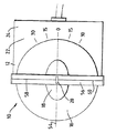
以下、図面を参照して説明する。各々の図において同様な又は対応する部品には同じ参照数字が付してある。図1および2は、本発明の第1の好ましい実施態様による渦電流型検知システム用の渦電流プローブ10を示す。ここで、渦電流検査システムは渦電流プローブ10からの信号を処理して表示し、このような処理および表示は当業者に周知であって、本発明の一部を構成しないことに留意されたい。本発明の渦電流プローブ10は、支持部材12、全体的に環状の第1の弾性部材14、弾性膜16、第2の弾性部材18および可撓性の渦電流検知コイル20を含む。典型的には、渦電流プローブ10はまた、当業者に理解されるように可撓性の渦電流駆動コイル(図の簡単化のために図示していない)を含む。
【0007】
支持部材12は、好ましくは、対向する第1および第2の面24および26を持つプラスチック基板22である。しかし、支持部材12は任意の形状を有していてよい。支持部材12の好ましい材料はプラスチックである。
全体的に環状の第1の弾性部材14は第1の弾性係数を持ち、また縦軸線28および外面30を持つ。外面30は、中孔33を画成する全体的に半径方向内側を向いた面部分32、全体的に半径方向外側を向いた面部分34、並びに各々がこれらの面部分32および34に接続された全体的に対向する第1および第2の端面部分36および38を含む。第1の端面部分36は支持部材12に接触する。好ましくは、第1の弾性部材14の外面30の第1の端面部分36は、基板22の第1の面24に接触し且つそれに取り付けられる。図1に示した第1の好ましい実施態様では、第1の弾性部材14は、これに限定されるものではないが、RTV(室温加硫)シリコーンのような弾性材料の単一のモノリシック・リングである。
【0008】
図3に示されている第2の好ましい実施態様では、第1の弾性部材114は、縦軸線28とほぼ同軸に配置されていて、基板22の第1の面24に取り付けられているゲル(gel)リング140、縦軸線28とほぼ同軸に配置されていて、ゲル・リング140に縦方向に取り付けられているフォーム(foam)リング142、および縦軸線28とほぼ同軸に配置されていて、フォーム・リング142に縦方向に取り付けられている環状のゴム接触遮蔽体144で構成されている。フォーム・リング142はゲル・リング140と環状のゴム接触遮蔽体144との間に縦方向に配置されている。ここで、ゲル・リング140、フォーム・リング142および環状のゴム接触遮蔽体144は全体的に同心であることに注意されたい。好ましくは、ゲル・リング140は本質的にRTVシリコーンで形成され、フォーム・リング142は本質的にネオプレン・スポンジ・ゴムで形成され、環状のゴム接触遮蔽体144は本質的にフォーム・ゴムで形成される。環状のゴム接触遮蔽体144は耐磨耗性を与え、ゲル・リング140(常に、フォーム・リング142よりも弾性である)は第1の弾性部材114が被検査面45(図1参照)に対して一層良好に順応できるようにし、フォーム・リング142は基板22を被検査面45から弾性隔離距離だけ隔てるための基本的な機械的支持を行う。
【0009】
第3の好ましい実施態様では、図4に示されるような配置形状のゲル・リング240およびフォーム・リング242が、環状のゴム接触遮蔽体144と共に、第1の弾性部材214を構成する。フォーム・リング242は、縦軸線28とほぼ同軸に配置されていて、ゲル・リング240に半径方向に取り付けられている。フォーム・リング242の内径はゲル・リング240の外径に大体等しい。このような設計は、凹面形の被検査面45に対して良好な順応性を持つ。
【0010】
第4の好ましい実施態様では、図5に示されるような配置形状のゲル・リング340およびフォーム・リング342が、環状のゴム接触遮蔽体144と共に、第1の弾性部材314を構成する。フォーム・リング342の外径はゲル・リング340の内径に大体等しい。このような設計は、凸面形の被検査面45に対して良好な順応性を持つ。
【0011】
弾性膜16は、全体的に中孔33全体を覆うように延在し、対向する第1および第2の面46および48を持つ。第1の面46は、第1の弾性部材14の外面30の第2の端面部分38と接触しているが、第1の弾性部材14の外面30の全体的に半径方向内側を向いた面部分32には付着していない。一構成例では、弾性膜16の第1の面46は第1の弾性部材14の外面30の第2の端面部分38に取り付けられる。弾性膜16はまた基板22に取り付けることが望ましい。好ましくは、弾性膜16は本質的にラテックス・ゴムで形成される。図3に示されるように第1の弾性部材114が環状のゴム接触遮蔽体144を含んでいる場合、弾性膜16の第1の面46は環状のゴム接触遮蔽体144に取り付けられる。
【0012】
第2の弾性部材18は、第1の弾性部材14の第1の弾性係数よりも大きい第2の弾性係数を持つ。第2の弾性部材18は、中孔33の中に配置されるが、第1の弾性部材14に付着していず、また全体的に対向する第1および第2の面50および52を持つ。ここで、第2の弾性部材18の第1の面50が弾性膜16の第2の面48に接触していることに注意されたい。
【0013】
可撓性の渦電流検知コイル20が第2の弾性部材18の第2の面52の一部分の上に配置される。好ましくは、渦電流検知コイル20は第2の弾性部材18の第2の面52上に位置する唯一の渦電流検知コイルである。好ましい構成では、渦電流検知コイル20は、長さ方向軸線54を持ち且つ長さ対幅比が少なくとも3(好ましくは、少なくとも6)である全体的に矩形の形状を持つ。ここで、好ましい細長の矩形の形状の単一の渦電流検知コイル20が公知の多コイル・システムと同じ検査範囲を提供することに注意されたい。このような好ましい構成の場合、第2の弾性部材18が全体的に楕円体形状を持ち、その主軸を渦電流検知コイル20の長さ方向軸線54と大体平行に揃えることが望ましい。しかし、渦電流検知コイル20は任意の形状を持っていてよく、また離間配置されて電気接続された複数のサブコイルの任意の組合せでもよい。
【0014】
渦電流検知コイル20は基板22に回転自在に取り付けて、縦軸線28の周りを回転できるようにすることが好ましい。回転自在の渦電流検知コイル20の場合、渦電流プローブ10が、基板22に関して固定された基準方向に対して、縦軸線28の周りの渦電流検知コイル20の長さ方向軸線54の回転角度を測定する手段を含んでいることが望ましい。このような測定手段は、図2に示されているように基板22の第1の面24上に角度マークを含んでいることが好ましい。他の測定手段としては、当業者に周知のように、このような角度のディジタル読出し手段などを含むものである。本発明者は、被検査面45に沿った渦電流プローブ10の進行方向からある角度だけ渦電流検知コイル20をずらすことにより傷をより容易に検出できることを見出した。
【0015】
本発明の好ましい実施態様では、渦電流プローブ10はまた、可撓性の電気リード58および60を収容する可撓性のポリイミド・フィルム56を含む。渦電流検知コイル20がポリイミド・フィルム56の中に配置されて、電気リード58および60に接続される。望ましい構成では、ポリイミド・フィルム56は基板22に取り付けられる(好ましくは、回転自在に取り付けられる)。
【0016】
渦電流プローブ10の更に取り得る一例として、ポリイミド・フィルム56を覆うようにポリアミドのメッシュ生地62が配置される。ポリアミドのメッシュ生地62が実際に被検査面45に接触する部材になる。ポリアミドのメッシュ生地62の目的は、容易に取り替えることができ、被検査面45との接触により磨耗することである。この目的にはテフロン(登録商標)テープを使用することが出来る。
【0017】
好ましい構成では、渦電流プローブ10は更に、基板22の第2の面26に取り付けられ且つ渦電流検知コイル20に電気接続された信号増幅器64を含む。これにより、従来の渦電流検査システムと比べて、信号増幅器64が渦電流検知コイル20の近くに配置される。信号増幅器64および渦電流検知コイル20を本質的に同じ位置に置くことにより、信号対雑音比が改善され、従って傷の検出が改善される。
【0018】
上述した渦電流プローブ10は、操作者が手で持つことができ、また可撓性の渦電流検知コイル20の背部に本質的に一定の力を供給することができる。この力は、操作者が被検査面に対してプローブ10を押し付けたり又は被検査面に沿ってプローブ10を動かすために加える可変の圧力から全体的にデカップリングされる。希望により、プローブ10は機械的制御システムによって移動させるようにしてもよいが、好ましい操作モードはプローブ10を手で動かすことである。安定性のために、手によるプローブの移動を案内するためにジグを使用してもよい。図1は、手に順応性のあるプラスチック・ハウジング66を更に示している。このプラスチック・ハウジング66は、基板22の第2の面26を覆うと共に、渦電流検査システムの信号処理及び画像表示部分へ延在するケーブル68や図に示されていない他の部分を覆う。
【0019】
渦電流プローブ10の特定の実施態様を検討することにより、当業者には、本願の基本的発明が(前述のプローブ構成部品を含めて)より一般的に、傷の有無を検査すべき物体の被検査面45に接近するように移動可能な支持部材12、および支持部材12が被検査面45に接近するように移動されたとき支持部材12と被検査面45との間に隔離距離を定める第1の手段を含む、渦電流型検知システム用プローブ10のような、プローブとして記述されることが理解されよう。第1の手段は、支持部材12が被検査面45に接近するように移動されたとき、被検査面45および支持部材12に接触する。このような接近移動は、被検査面45へ直接向かう接近移動を含み、更に好ましくは被検査面45に沿った接近移動も含む。好ましくは、第1の手段は、前述の第1の弾性部材14、前述の弾性膜16の重なる部分、および前述のポリアミドのメッシュ生地62の重なる部分を含む。他の第1の手段は、1つ以上の任意の形状の堅固な及び/又は弾性のブロック部材を含み、弾性はバネ、ガス、液体、エラストマーなどで与えることが出来る。
【0020】
より一般的に記述されるプローブ10はまた、第1の手段が被検査面45に接触したとき被検査面45に所定の力を加えるための第2の手段を含む。第2の手段全体は、支持部材12の近くに位置決めされていて、支持部材12が被検査面45に接近するとき被検査面45に接近する。第2の手段は、第1の手段が被検査面45に接触したときに被検査面45に接触する。所定の力は、第1の手段が被検査面45に接触したときに第1の手段によって被検査面45に加えられる力から全体的にデカップリングされる。第2の手段は、第1の手段が被検査面45に接触したときに被検査面45の近くに位置決めされる(可撓性の渦電流検知コイル20のような)可撓性の検知装置を含む。好ましくは、第2の手段はまた、前述の弾性膜16、前述の第2の弾性部材18、前述の可撓性のポリイミド・フィルム56、および前述のポリアミドのメッシュ生地62の重なる部分を含む。他の第2の手段はまた、渦電流検知コイル20の背後に配置され、第1の手段に取り付けられていず、且つ支持部材12に取り付けられる(或いは、支持部材12の近くに留まるように何らかの手段で拘束される)ガスまたは液体充填ブラダ(bladder)、バネ、エラストマーなどを含む。当業者には理解されるように、上述の第2の手段は所定の大体一定の力を供給し、この力は第1の手段によって被検査面45に加えられる力から全体的にデカップリングされる。可撓性の検知装置としては、これに限定されないが、当業者に理解され得るように、前述の渦電流検知コイル20、超音波試験のためのポリ弗化ビニリデンのような強誘電体ポリマー、圧力試験のための2つのコンデンサ板、熱伝対など、およびそれらの組合せが挙げられる。ここで、第2の手段が典型的には(可撓性の渦電流駆動コイルのような)可撓性の駆動装置も含んでおり、この駆動装置が用途によっては検知装置と同じ構造(例えば、特定の超音波用途で使用される共通の送信−受信トランスジューサ)を時分割使用することに留意されたい。
【0021】
上記のより一般的に記述されるプローブ10の好ましい実施態様を以下に示す。支持部材12、第1の手段および第2の手段は一緒に手持ち可能である。第2の手段は、被検査面45に接近する支持部材12の移動によってのみ所定の力を供給する。第2の手段全体は、第1の手段が被検査面45に接触したとき、支持部材12と被検査面45との間の隔離距離内に配置される。第2の手段は第1の手段よりも一層弾性である。
【0022】
好ましくは、渦電流検知コイル20は第2の手段内に含まれる唯一の渦電流検知コイルであり、また渦電流検知コイル20は、長さ方向軸線54を持ち且つ長さ対幅比が少なくとも3(好ましくは、少なくとも6)である全体的に矩形の形状を持つ。渦電流検知コイル20は支持部材12に回転自在に取り付けられる。渦電流プローブ10がまた、支持部材12に関して固定された基準方向に対して、渦電流検知コイル20の長さ方向軸線54の回転角度を測定する第3の手段を含む。このような第3の手段は、前に述べた角度測定手段と等価である。渦電流プローブ10は更に、支持部材12に取り付けられ且つ渦電流検知コイル20に電気接続された信号増幅器64を含む。
【0023】
図6は本発明の別の実施態様を示す。この実施態様の渦電流プローブ10′は、支持部材12′、縦軸線28′を持つ全体的に環状の第1の弾性部材14′、第2の弾性部材18′、可撓性の渦電流検知コイル20′、およびポリアミドのメッシュ生地62′を含む。
上記の幾つかの好ましい実施態様は例示の目的で提示した。本発明は上記の形態そのものに限定されず、上記の教示するところから種々の変更および変形をなし得ることは明らかであろう。本発明の範囲は特許請求の範囲によって定められるものである。
【図面の簡単な説明】
【図1】本発明の第1の好ましい実施態様による第1の弾性部材を含む渦電流型検知システム用プローブの概略断面図である。
【図2】図1の線2−2に沿って取った図1の渦電流プローブの底面図である。
【図3】本発明の渦電流プローブの第2の好ましい実施態様による第1の弾性部材とその隣接部材とを示す概略断面図である。
【図4】本発明の渦電流プローブの第3の好ましい実施態様による第1の弾性部材とその隣接部材とを示す、図3と同様な概略断面図である。
【図5】本発明の渦電流プローブの第4の好ましい実施態様による第1の弾性部材とその隣接部材とを示す、図3と同様な概略断面図である。
【図6】本発明の別の実施態様の渦電流プローブの、図1と同様であるが一部分のみを示す概略断面図である。
【符号の説明】
10 渦電流プローブ
12 支持部材
14、114、214,314 第1の弾性部材
16 弾性膜
18 第2の弾性部材
20 渦電流検知コイル
22 基板
28 縦軸線
30 外面
32 全体的に半径方向内側を向いた面部分
33 中孔
34 全体的に半径方向外側を向いた面部分
36 第1の端面部分
38 第2の端面部分
45 被検査面
140、240、340 ゲル・リング
142、242、342 フォーム・リング
144 環状のゴム接触遮蔽体[0001]
BACKGROUND OF THE INVENTION
The present invention relates generally to detection systems (such as eddy current inspection systems for detecting flaws in conductive articles), and more particularly to detection systems (such as eddy current probes for eddy current inspection systems). It relates to a hand-held probe for use.
[0002]
[Prior art]
Eddy current inspection systems that use non-destructive eddy currents to detect scratches or defects present on or near the surface of a conductive article are well known. Such inspection systems typically use circular eddy current probes, each probe having an eddy current drive coil and an eddy current sensing coil (even though the drive and sense coils are the same coil, separate coils). May be). However, known probes comprise a large number of individually sensing, generally identical, flexible eddy current sensing coils arranged in a rectangular array arranged in a number of rows and a number of offset columns, The eddy current detection coil is formed in a rectangular shape having a length to width ratio of approximately 2. Optimal efficiency of the eddy current sensing coil occurs when the sensing device is placed in direct contact with the part under inspection. In order to obtain consistent and repeatable test results with a sufficient signal-to-noise ratio, it is necessary to apply uniform pressure. Accordingly, curved surfaces (ie, smoothly changing convex and concave surfaces including rounded corners) cause problems for eddy current flaw detection systems. A known solution uses a compressed gas with controlled pressure against the back of the flexible eddy current sensing coil array in the eddy current probe, which is under the control of a multi-axis mechanical control system. It is to operate accurately for the part under inspection. Similar problems can be understood by those skilled in the art, ferroelectric polymers such as polyvinylidene fluoride for ultrasonic testing, two capacitor plates for pressure testing, thermocouples, etc., and their It also occurs in other sensing system probes that contain combinations.
[0003]
[Problems to be solved by the invention]
Therefore, as a detection system probe (such as an eddy current type detection system probe), it is inexpensive, handheld, and built-in to apply uniform pressure to a flat or smoothly curved surface. There is a need for a probe that has better or equivalent sensitivity than conventional probes that are essentially connected to a mechanical positioning control system.
[0004]
[Means for Solving the Problems]
The probe of the present invention has a support member that can be moved so as to approach the surface to be inspected of an object to be inspected for scratches, and the support member and the surface to be inspected when the support member is moved so as to approach the surface to be inspected And a second device for applying a predetermined force to the surface to be inspected when the first device contacts the surface to be inspected. The first device contacts the surface to be inspected and the support member when the support member is moved so as to approach the surface to be inspected. The entire second device is positioned near the support member and moves so as to approach the surface to be inspected when the first device contacts the surface to be inspected. The predetermined force is totally decoupled or decoupled from the force applied to the surface to be inspected by the first device when the first device contacts the surface to be inspected. The second device includes a flexible sensing device that is positioned near the surface to be inspected when the first device contacts the surface to be inspected.
[0005]
The present invention provides several benefits and advantages. The probe of the present invention can be held by an operator by hand and can provide an essentially constant force to the back of a flexible sensing device. This force can be applied by the operator to press the probe against or move the probe along the surface to be inspected without the need for an expensive multi-axis mechanical control system or a cumbersome compressed gas supply Is decoupled from the total pressure.
[0006]
DETAILED DESCRIPTION OF THE INVENTION
Hereinafter, description will be given with reference to the drawings. Similar or corresponding parts in the various figures are marked with the same reference numerals. 1 and 2 show an eddy
[0007]
The
The generally annular first
[0008]
In the second preferred embodiment shown in FIG. 3, the first
[0009]
In the third preferred embodiment, the
[0010]
In the fourth preferred embodiment, the
[0011]
The
[0012]
The second
[0013]
A flexible eddy
[0014]
It is preferable that the eddy
[0015]
In the preferred embodiment of the present invention,
[0016]
As a further possible example of the
[0017]
In a preferred configuration, the
[0018]
The
[0019]
By examining specific embodiments of the
[0020]
The
[0021]
A preferred embodiment of the
[0022]
Preferably, the eddy
[0023]
FIG. 6 shows another embodiment of the present invention. The eddy current probe 10 'of this embodiment comprises a support member 12', a generally annular first elastic member 14 'having a longitudinal axis 28', a second elastic member 18 ', flexible eddy current sensing. It includes a coil 20 'and a polyamide mesh fabric 62'.
Some of the preferred embodiments described above have been presented for purposes of illustration. It will be apparent that the invention is not limited to the precise forms described above and that various modifications and variations can be made from the teachings above. The scope of the present invention is defined by the appended claims.
[Brief description of the drawings]
FIG. 1 is a schematic cross-sectional view of an eddy current detection system probe including a first elastic member according to a first preferred embodiment of the present invention.
2 is a bottom view of the eddy current probe of FIG. 1 taken along line 2-2 of FIG.
FIG. 3 is a schematic sectional view showing a first elastic member and its adjacent members according to a second preferred embodiment of the eddy current probe of the present invention.
FIG. 4 is a schematic sectional view similar to FIG. 3, showing a first elastic member and its adjacent members according to a third preferred embodiment of the eddy current probe of the present invention.
FIG. 5 is a schematic sectional view similar to FIG. 3, showing a first elastic member and its adjacent members according to a fourth preferred embodiment of the eddy current probe of the present invention.
6 is a schematic cross-sectional view similar to FIG. 1 but showing only a portion of an eddy current probe of another embodiment of the present invention. FIG.
[Explanation of symbols]
DESCRIPTION OF
Claims (6)
b)第1の弾性係数を持ち、縦軸線(28)と中孔(33)とを有する全体的に環状の第1の弾性部材(14)を含む第1の手段(14)であって、前記支持部材(12)が前記被検査面(45)に接近するように移動したときに前記支持部材(12)と前記被検査面(45)との間に隔離距離を定め、前記支持部材(12)が前記被検査面(45)に接近するように移動したときに前記被検査面(45)および前記支持部材(12)と接触する第1の手段(14)と、
c)前記第1の手段(14)が前記被検査面(45)と接触したときに前記被検査面(45)に所定の力を加えるため、前記第1の弾性部材(14)の第1の弾性係数よりも大きい第2の弾性係数を持ち、前記中孔(33)の中に配置された第2の弾性部材(18)を含む第2の手段(18)であって、前記第2の手段全体が、前記支持部材(12)の近くに位置決めされていて、前記支持部材(12)が前記被検査面(45)に接近するように移動したときに前記被検査面(45)に接近するように移動するとともに、前記第1の手段が前記被検査面(45)と接触したときに前記被検査面(45)と接触し、前記所定の力が、前記第1の手段が前記被検査面(45)と接触したときに前記第1の手段によって前記被検査面(45)に加えられる力から全体的にデカップリングされ、更に当該第2の手段が、前記第1の手段が前記被検査面(45)と接触したときに前記被検査面(45)の近くに位置決めされる可撓性の検知装置(20)を含んでいる第2の手段(18)を有するプローブ。 a) a support member (12) movable so as to approach the surface to be inspected (45) of the object to be inspected for scratches;
b) first means (14) comprising a generally annular first elastic member (14) having a first elastic modulus and having a longitudinal axis (28) and a bore (33), define a separation distance between the supporting member (12) and the surface to be inspected (45) when said support member (12) is moved so as to approach the to be inspected surface (45), said support member (12) first means (14) in contact with said when moving the inspected surface (45) and said supporting member (12) so as to approach the surface to be inspected (45),
c) for applying a predetermined force said to be inspected surface (45) when said first means (14) has a contact with the surface to be inspected (45), first the first elastic member (14) A second means (18) having a second elastic modulus greater than the elastic modulus of the second hole (33) and including a second elastic member (18) disposed in the inner hole (33) . the entire unit, said support member (12) of being positioned near the surface to be inspected when said support member (12) is moved so as to approach the the surface to be inspected (45) (45) while moving to approach the said contact with the surface to be inspected (45) when said first means is the contact with the surface to be inspected (45), the predetermined force is, the first means in addition the to the inspection surface by said first means when in contact with the surface to be inspected (45) (45) Is totally decoupled from the force, variable further has the second means, wherein is positioned close to the inspected surface (45) when said first means is the contact with the surface to be inspected (45) second means (18) probes that have a that contain FLEXIBLE sensing device (20).
Applications Claiming Priority (2)
| Application Number | Priority Date | Filing Date | Title |
|---|---|---|---|
| US08/803612 | 1997-02-21 | ||
| US08/803,612 US5841277A (en) | 1996-07-30 | 1997-02-21 | Hand-holdable probe having a flexible eddy current sensor |
Publications (2)
| Publication Number | Publication Date |
|---|---|
| JPH10307125A JPH10307125A (en) | 1998-11-17 |
| JP4142145B2 true JP4142145B2 (en) | 2008-08-27 |
Family
ID=25187001
Family Applications (1)
| Application Number | Title | Priority Date | Filing Date |
|---|---|---|---|
| JP03650898A Expired - Fee Related JP4142145B2 (en) | 1997-02-21 | 1998-02-19 | probe |
Country Status (4)
| Country | Link |
|---|---|
| US (1) | US5841277A (en) |
| EP (1) | EP0860697B1 (en) |
| JP (1) | JP4142145B2 (en) |
| DE (1) | DE69839537D1 (en) |
Families Citing this family (23)
| Publication number | Priority date | Publication date | Assignee | Title |
|---|---|---|---|---|
| WO1999023484A1 (en) * | 1997-11-04 | 1999-05-14 | Siemens Aktiengesellschaft | Probe for eddy current testing, method for producing a probe for eddy current testing and method for eddy current testing |
| US6288537B1 (en) * | 1999-12-22 | 2001-09-11 | General Electric Company | Eddy current probe with foil sensor mounted on flexible probe tip and method of use |
| US6670808B2 (en) * | 2001-08-27 | 2003-12-30 | General Electric Company | Self reference eddy current probe, measurement system, and measurement method |
| US6894492B1 (en) * | 2001-12-07 | 2005-05-17 | General Electric Company | Self-aligning probe and its use |
| US6812697B2 (en) * | 2002-09-24 | 2004-11-02 | General Electric Company | Molded eddy current array probe |
| US20040257072A1 (en) * | 2003-06-19 | 2004-12-23 | Rock Samson | Dual-sensitivity eddy current test probe |
| US7795863B2 (en) * | 2004-02-23 | 2010-09-14 | Iowa State University Research Foundation, Inc. | Method and apparatus for forming coil for use in eddy current sensing probe |
| US7375514B2 (en) * | 2005-11-01 | 2008-05-20 | The Boeing Company | Flexible hand held MR scanning array for cracks/flaws |
| US7312608B2 (en) * | 2005-11-03 | 2007-12-25 | The Boeing Company | Systems and methods for inspecting electrical conductivity in composite materials |
| US7852073B2 (en) * | 2007-06-25 | 2010-12-14 | Southwest Research Institute | Method and device for long-range torsional guided-wave inspection of piping with a partial excitation and detection around the pipe circumference |
| US7952348B2 (en) * | 2007-11-05 | 2011-05-31 | General Electric Company | Flexible eddy current array probe and methods of assembling the same |
| US7888932B2 (en) * | 2007-11-05 | 2011-02-15 | General Electric Company | Surface flaw detection system to facilitate nondestructive inspection of a component and methods of assembling the same |
| US8098065B2 (en) * | 2008-08-29 | 2012-01-17 | Southwest Research Institute | Magnetostrictive sensor probe for guided-wave inspection and monitoring of wire ropes/cables and anchor rods |
| US7913562B2 (en) * | 2008-08-29 | 2011-03-29 | Southwest Research Institute | Flexible plate magnetostrictive sensor probe for guided-wave inspection of structures |
| US8269489B2 (en) * | 2008-11-25 | 2012-09-18 | General Electric Company | System and method for eddy current inspection of parts with complex geometries |
| US9932852B2 (en) * | 2011-08-08 | 2018-04-03 | General Electric Company | Sensor assembly for rotating devices and methods for fabricating |
| US8884614B2 (en) | 2011-10-31 | 2014-11-11 | General Electric Company | Eddy current array probe |
| US9646599B2 (en) * | 2013-10-24 | 2017-05-09 | Spirit Aerosystems, Inc. | Remoldable contour sensor holder |
| US10119942B2 (en) | 2015-02-13 | 2018-11-06 | Fbs, Inc. | Medium-range magnetostrictive ultrasonic guided wave scanner systems and methods |
| US9915632B2 (en) | 2015-04-06 | 2018-03-13 | Fbs, Inc. | Long-range magnetostrictive ultrasonic guided wave scanner system and method |
| FR3058522B1 (en) * | 2016-11-10 | 2021-01-29 | Commissariat Energie Atomique | CONTROL HEAD FOR EDDY CURRENT SENSORS |
| US11402352B1 (en) * | 2019-08-20 | 2022-08-02 | Scan Systems Corp. | Apparatus, systems, and methods for inspecting tubulars employing flexible inspection shoes |
| US20240027546A1 (en) * | 2022-07-20 | 2024-01-25 | General Electric Company | Magneto-Optic Defect Visualization System |
Family Cites Families (14)
| Publication number | Priority date | Publication date | Assignee | Title |
|---|---|---|---|---|
| US3523241A (en) * | 1968-11-26 | 1970-08-04 | American Mach & Foundry | Flexible search shoe |
| GB2009563A (en) * | 1977-11-24 | 1979-06-13 | Emi Ltd | Ultrasonic probes |
| US4143553A (en) * | 1977-12-19 | 1979-03-13 | Automation Industries, Inc. | Contoured search unit for detecting internal flaws |
| US4303884A (en) * | 1978-10-19 | 1981-12-01 | Westinghouse Electric Corp. | Inflatable eddy current inspection probe for inspection of tubular means |
| US4543528A (en) * | 1982-09-30 | 1985-09-24 | Republic Steel Corporation | Flexible probe assembly for use in nondestructive testing of a convex workpiece surface |
| EP0228177A3 (en) * | 1985-11-19 | 1988-11-02 | Electric Power Research Institute, Inc | Flexible eddy-current coil and coil array for nondestructive testing |
| US5047719A (en) * | 1990-05-25 | 1991-09-10 | The Failure Group, Inc. | Flexible coil assembly for reflectance-mode nondestructive eddy-current examination |
| US5182513A (en) * | 1991-04-06 | 1993-01-26 | General Electric Company | Method and apparatus for a multi-channel multi-frequency data acquisition system for nondestructive eddy current inspection testing |
| US5389876A (en) * | 1991-05-06 | 1995-02-14 | General Electric Company | Flexible eddy current surface measurement array for detecting near surface flaws in a conductive part |
| US5345514A (en) * | 1991-09-16 | 1994-09-06 | General Electric Company | Method for inspecting components having complex geometric shapes |
| US5315234A (en) * | 1992-04-03 | 1994-05-24 | General Electric Company | Eddy current device for inspecting a component having a flexible support with a plural sensor array |
| US5262722A (en) * | 1992-04-03 | 1993-11-16 | General Electric Company | Apparatus for near surface nondestructive eddy current scanning of a conductive part using a multi-layer eddy current probe array |
| US5371462A (en) * | 1993-03-19 | 1994-12-06 | General Electric Company | Eddy current inspection method employing a probe array with test and reference data acquisition and signal processing |
| US5442286A (en) * | 1993-09-22 | 1995-08-15 | General Electric Company | Eddy current array inspection device |
-
1997
- 1997-02-21 US US08/803,612 patent/US5841277A/en not_active Expired - Lifetime
-
1998
- 1998-02-11 EP EP98300995A patent/EP0860697B1/en not_active Expired - Lifetime
- 1998-02-11 DE DE69839537T patent/DE69839537D1/en not_active Expired - Lifetime
- 1998-02-19 JP JP03650898A patent/JP4142145B2/en not_active Expired - Fee Related
Also Published As
| Publication number | Publication date |
|---|---|
| DE69839537D1 (en) | 2008-07-10 |
| EP0860697B1 (en) | 2008-05-28 |
| US5841277A (en) | 1998-11-24 |
| JPH10307125A (en) | 1998-11-17 |
| EP0860697A3 (en) | 2000-07-19 |
| EP0860697A2 (en) | 1998-08-26 |
Similar Documents
| Publication | Publication Date | Title |
|---|---|---|
| JP4142145B2 (en) | probe | |
| JP4048333B2 (en) | Eddy current probe | |
| US5895871A (en) | Finger controlled inspection apparatus | |
| EP2282187B1 (en) | Inspecting device including detachable probe | |
| US7913562B2 (en) | Flexible plate magnetostrictive sensor probe for guided-wave inspection of structures | |
| US20200321665A1 (en) | Modular, adaptable holders for sensors and battery cells for physical analysis | |
| US8069735B1 (en) | Tactile sensor array for soft tissue elasticity imaging | |
| JPH0345541B2 (en) | ||
| AU2018213406C1 (en) | Form-fitting eddy current array sensor and method of use thereof | |
| JP4226105B2 (en) | Probe and method for inspecting an object | |
| US7542871B2 (en) | Control for hand-held imaging array using computer mouse configuration | |
| US7183764B2 (en) | Method for inspecting a channel using a flexible sensor | |
| US4519251A (en) | Roller-type ultrasonic inspection device with acoustical isolation | |
| CA2956172A1 (en) | A measurement instrument for testing charge storage devices | |
| US8310682B2 (en) | Apparatus, system and methods for analyzing pressure-sensitive devices | |
| JP2014115128A (en) | Measuring tool having sensors | |
| US10866213B2 (en) | Eddy current probe | |
| JP2018159563A (en) | Gas sensor device and gas leak detection device | |
| JP4391966B2 (en) | Method for measuring shape of surface of object to be measured and apparatus for measuring shape of surface of object to be measured | |
| RU2002133933A (en) | METHOD FOR ELECTRIC NON-DESTRUCTIVE CONTROL OF MATERIALS AND DEVICE FOR ITS IMPLEMENTATION | |
| RU2086908C1 (en) | Stand for checking roughness indicators | |
| SU1727061A1 (en) | Device for determining surface electric conductivity of sheet materials | |
| JPH01311246A (en) | Bearing testing device | |
| JPH08178817A (en) | Mapping sensor and sensing apparatus | |
| JP2012013634A (en) | Pressure sensor |
Legal Events
| Date | Code | Title | Description |
|---|---|---|---|
| A621 | Written request for application examination |
Free format text: JAPANESE INTERMEDIATE CODE: A621 Effective date: 20050127 |
|
| A131 | Notification of reasons for refusal |
Free format text: JAPANESE INTERMEDIATE CODE: A131 Effective date: 20071016 |
|
| A601 | Written request for extension of time |
Free format text: JAPANESE INTERMEDIATE CODE: A601 Effective date: 20080116 |
|
| A602 | Written permission of extension of time |
Free format text: JAPANESE INTERMEDIATE CODE: A602 Effective date: 20080121 |
|
| A521 | Request for written amendment filed |
Free format text: JAPANESE INTERMEDIATE CODE: A523 Effective date: 20080415 |
|
| TRDD | Decision of grant or rejection written | ||
| A01 | Written decision to grant a patent or to grant a registration (utility model) |
Free format text: JAPANESE INTERMEDIATE CODE: A01 Effective date: 20080513 |
|
| A01 | Written decision to grant a patent or to grant a registration (utility model) |
Free format text: JAPANESE INTERMEDIATE CODE: A01 |
|
| A61 | First payment of annual fees (during grant procedure) |
Free format text: JAPANESE INTERMEDIATE CODE: A61 Effective date: 20080612 |
|
| FPAY | Renewal fee payment (event date is renewal date of database) |
Free format text: PAYMENT UNTIL: 20110620 Year of fee payment: 3 |
|
| R150 | Certificate of patent or registration of utility model |
Free format text: JAPANESE INTERMEDIATE CODE: R150 |
|
| LAPS | Cancellation because of no payment of annual fees |