JP4139877B2 - Sterilization method and apparatus - Google Patents
Sterilization method and apparatus Download PDFInfo
- Publication number
- JP4139877B2 JP4139877B2 JP2003047777A JP2003047777A JP4139877B2 JP 4139877 B2 JP4139877 B2 JP 4139877B2 JP 2003047777 A JP2003047777 A JP 2003047777A JP 2003047777 A JP2003047777 A JP 2003047777A JP 4139877 B2 JP4139877 B2 JP 4139877B2
- Authority
- JP
- Japan
- Prior art keywords
- electrode
- current
- liquid
- sterilization
- sterilization method
- Prior art date
- Legal status (The legal status is an assumption and is not a legal conclusion. Google has not performed a legal analysis and makes no representation as to the accuracy of the status listed.)
- Expired - Lifetime
Links
Images


Description
【0001】
【発明の属する技術分野】
本発明は、滅菌方法およびその装置に関し、一層詳細には、様々な種類の菌やウィルスを滅菌するために要する時間が著しく短い滅菌方法およびその装置に関する。
【0002】
【従来の技術】
食肉、魚貝類、野菜、果物等の食材に対しては、一般小売店や百貨店等に出荷される前、次亜塩素酸ナトリウム水溶液、アルコール、紫外線、オゾン等による滅菌処理が施される。これによりO−157等の病原性大腸菌や、サルモネラ菌等の細胞侵入性大腸菌の数、さらには、小型球形ウィルス、アストロウィルス、ロタウィルス等のウィルスの数が激減し、その結果、食中毒が防止される。
【0003】
しかしながら、上記したような滅菌剤を使用しての滅菌では、滅菌剤の臭いが食材に残留したり、食材の色が変化したりするという不具合がある。そこで、魚貝類を洗浄する場合であれば、例えば、特許文献1にて提案されているように、滅菌剤を使用することなく殺菌作用および防腐作用を営む海水を得ることが想起される。
【0004】
【特許文献1】
特開2002−307070号公報(段落[0021]〜[0023])
【0005】
【発明が解決しようとする課題】
ところで、特許文献1に記載された方法においては、海水に対して一定電圧を8〜10秒間程印加して滅菌を行うようにしている。この滅菌時間に関し、更なる時間短縮が希求されている。
【0006】
本発明は上記した技術に関連してなされたもので、様々な菌、細菌およびウィルスに対する滅菌能を有し、しかも、その滅菌処理に要する時間が著しく短い滅菌方法およびその装置を提供することを目的とする。
【0007】
【課題を解決するための手段】
前記の目的を達成するために、本発明は、液体中に存在する菌類を滅菌する滅菌方法であって、
前記液体に接触する第1電極および第2電極の間に、前記第1電極から前記第2電極に指向して流れる電流を供給する第1工程と、
前記電流の方向を前記第2電極から前記第1電極に反転させて通電する第2工程と、
を有し、
前記第1工程および前記第2工程における通電時間をともに1秒以下とすることを特徴とする。なお、本発明において、「菌類」とは、菌、細菌およびウィルスの総称であり、「滅菌」には、細菌やウィルスが死滅することも含まれるものとする。
【0008】
電流の流れる方向がこのように頻繁に反転されるので、イオン等の電荷が液体中を激しく移動するようになる。このため、電荷が大きな運動量で菌類に衝突するようになり、その結果、該菌類が迅速に死滅するに至ると推察される。これにより、滅菌処理に要する時間が著しく短縮される。
【0009】
このように滅菌処理された液体を食材等の洗浄液として使用するようにしてもよいし、食材や患部を液体に浸漬した上で上記の第1工程および第2工程を交互に繰り返すようにしてもよい。
【0010】
液体の好適な例としては、塩素イオンを含有する水を挙げることができる。塩素イオンは、例えば、NaClを水に溶解することによって得るようにすればよい。このNaClが電解質としての役割を果たすことによって水の電気抵抗が減少するので、第1工程および第2工程における通電を容易に行うことができる。
【0011】
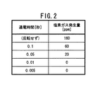
この場合、塩素イオンが電子と結合して塩素ガスが発生することを回避するために、第1工程および第2工程における通電時間をともに0.01秒以下とすることが好ましい。
【0012】
本発明によれば、電気抵抗が1×10⁶Ω・cm以上であるような液体、すなわち、純水や超純水等の絶縁体に対しても滅菌処理を施すことができる。この場合、第1電極と第2電極との間にイオン交換膜を介装し、かつ第1電極と第2電極に電気的に接続された導電体に液体を流通または貯留させて、第1工程および第2工程を遂行すればよい。
【0013】
いずれの場合においても、電流は、矩形波として通電することが好ましい。この場合、電流の流れる方向が急速に反転されるので、正弦波である一般的な交流電流を通電した場合に比して電荷の運動量が大きくなり、したがって、菌類を比較的短時間で死滅させることができるからである。
【0014】
さらに、通電の際に液体を振動させることが好ましい。例えば、食材を液体に浸漬して滅菌処理を施す場合、振動によって食材から菌類が容易に離脱する。このため、菌類を確実に死滅させることができる。
【0015】
また、本発明は、液体中に存在する菌類を滅菌するための滅菌装置であって、
前記液体に接触する第1電極および第2電極と、
前記第1電極と前記第2電極との間に流れる電流の方向を反転させる電流反転機構を具備する電流供給機構と、
を有することを特徴とする。
【0016】
このような構成とすることにより、電流の流れる方向を容易かつ簡便に反転させることができ、結局、滅菌処理を容易かつ確実に実施することができる。
【0017】
また、第1電極と第2電極に介装されたイオン交換膜と、前記第1電極と前記第2電極に電気的に接続された導電体とをさらに有し、かつ前記導電体に液体を流通させる通路が設けられていることが好ましい。この場合、イオン交換膜を介してイオンの移動が起こることによって、第1電極と第2電極との間に電流が流れる。このため、絶縁体である液体に対して滅菌処理を施すことができるようになる。
【0018】
なお、電流供給機構は、直流電流を供給する直流電源と、電流反転機構としてのスイッチング回路とを有することが好ましい。これにより波形が矩形波となる交流電流を供給することができ、結局、液体中に存在する電荷の運動量を大きくすることができる。
【0019】
そして、液体を振動させる振動部材を有することが好ましい。振動部材で液体を振動させながら滅菌処理を施すことにより、例えば、食材から菌類を容易に離脱させることができ、該食材を容易かつ確実に滅菌することができる。
【0020】
【発明の実施の形態】
以下、本発明に係る滅菌方法につきそれを遂行する装置との関係で好適な実施の形態を挙げ、添付の図面を参照して詳細に説明する。
【0021】
図1に、本実施の形態に係る滅菌装置の概略構成図を示す。この滅菌装置10は、液体を貯留する容器12と、該容器12に設置された第1電極14および第2電極16と、これら第1電極14および第2電極16に電気的に接続された直流電源18と、該直流電源18と第1電極14および第2電極16との間に介在されたスイッチング回路20とを有する。
【0022】
この場合、容器12は、内径が30mm、高さが50mmの樹脂製有底円筒体であり、該容器12内に収容された液体は、NaClが濃度3%で溶解された水道水Wが20cm3収容されている。
【0023】
水道水Wには第1電極14および第2電極16が挿入されており、これにより第1電極14および第2電極16が水道水Wに接触している。これら第1電極14および第2電極16は、チタンの表面に厚み2μmの白金がコーティングされてなる。また、幅、高さおよび板厚は、0.95mm、100mm、10mmに設定されている。なお、第1電極14と第2電極16との間の距離は、10mmとすることができる。
【0024】
このような構成の第1電極14および第2電極16は、リード線22、24を介して前記直流電源18に電気的に接続されている。また、リード線22、24には、電流を一定値として安定に供給するための定電流回路25と、前記スイッチング回路20とが介装されている。
【0025】
このスイッチング回路20は、図示しないオシレータ(発振器)を内蔵しており、したがって、該スイッチング回路20を介して通電がなされた際、第1電極14から第2電極16に指向する電流の流れと、第2電極16から第1電極14に指向する電流の流れとが交番的に生じる。
【0026】
水道水Wには超音波振動子26が浸漬されており、該超音波振動子26は、ケーブル27を介して電源ユニット28に接続されている。この電源ユニット28からの通電がなされると、超音波振動子26が所定の周波数で振動する。
【0027】
次に、本実施の形態に係る滅菌方法につき説明する。この滅菌方法は、第1電極14から第2電極16に指向して流れる電流を供給する第1工程と、電流の方向を第2電極16から第1電極14に反転させて通電する第2工程とを有する。
【0028】
まず、第1工程において、直流電源18からリード線22、定電流回路25およびスイッチング回路20を介して直流電流を第1電極14に供給すると、水道水Wは導電性を有するので、第1電極14から第2電極16に指向して直流電流が流れる。直流電流は、勿論、第2電極16からリード線24、定電流回路25およびスイッチング回路20を介して直流電源18に戻る。なお、設定電圧値、設定電流値は、例えば、12V、1Aとすればよい。
【0029】
その一方で、電源ユニット28を付勢して超音波振動子26に通電することにより、該超音波振動子26を所定の周波数で振動させる。
【0030】
ここで、上記した設定電圧値および設定電流値である直流電流が通電されて所定の時間が経過すると、水道水W中でNaClが電離して生成したCl-イオンが正極である第1電極14に指向して移動し、該第1電極14上で電子と結合して塩素ガスとなる。換言すれば、第1電極14から有毒な塩素ガスが発生する。
【0031】
このような事態が発生することを回避するため、本実施の形態においては、塩素ガスが発生する以前に、スイッチング回路20によって電流の方向を反転させる。すなわち、第2工程において、直流電源18から供給された電流は、リード線24、定電流回路25およびスイッチング回路20を介して第2電極16へと通電され、さらに、第1電極14に指向して流れた後、リード線22、定電流回路25およびスイッチング回路20を介して直流電源18に戻る。勿論、この際にも超音波振動子26を所定の周波数で振動させる。
【0032】
そして、第2電極16から塩素ガスが発生する以前に、スイッチング回路20によって電流の方向が反転される。すなわち、第1工程が再度遂行され、さらにその後、第1電極14から塩素ガスが発生する以前にスイッチング回路20によって電流の方向が反転されて第2工程が再度営まれる。
【0033】
このようにして、塩素ガスが発生することを回避しながら、所定時間が経過するまで通電が実施される。
【0034】
この場合における第1工程、第2工程での各通電時間と、最初の第1工程を開始して20秒が経過した際の塩素ガスの発生量との関係を図2に示す。この図2から、第1工程および第2工程での各通電時間を0.01秒(10ミリ秒)とすれば、塩素ガスが発生することを回避することができることが諒解される。ここで、塩素ガスの発生量は、水道水W中の溶存量として求められた値である。
【0035】
電流の方向が10ミリ秒ごとに反転されることにより、水道水Wには、図3に示すように、波形が矩形波となる電流が流れることになる。このような矩形波の電流が通電された場合、波形が図4に示すように正弦波となる一般的な交流電流が通電された場合に比して、水中に存在する菌類の数が激減する。すなわち、水の滅菌が進行する。
【0036】
具体的には、通電が所定時間行われた水道水Wにつきサンプルを採取し、該サンプルから培養土にて培養を行って48時間後に菌類数(単位はCFU)を計測すると、図5に示すように、0.003秒(3ミリ秒)以降のサンプルでは、菌類数が増加しない。このことは、通電が開始されて3ミリ秒以降のサンプルには増殖し得る菌類が存在しないこと、すなわち、3ミリ秒という極めて短時間の間に菌類が死滅していることを表す。
【0037】
このように滅菌処理が施された水道水Wは、食材や食材加工機器を洗浄する際に使用することができる。この場合、次亜塩素酸ナトリウム水溶液やアルコールを使用する必要がないため、食材に塩素臭等が残留したり、食材が変色したりすることがないという利点がある。
【0038】
さらに、水に対して振動を与えているので、滅菌処理が効率よく進行する。
【0039】
勿論、同様にして、河川、港湾、湖沼、池等の水に対して滅菌処理を施すこともできる。
【0040】
また、この滅菌方法では、水中に存在する皮膚常在菌やレジオネラ菌等を死滅させることもできる。したがって、該滅菌方法により、湯水を循環させる循環風呂やプール、またはクアハウス等に使用する湯水を滅菌処理することもできる。勿論、この場合も、塩素や紫外線、オゾン等で滅菌する必要がなくなるので、刺激臭のない湯水を使用することができる。
【0041】
さらに、この滅菌方法は、火傷や外傷等の患部に繁殖した雑菌を消毒して滅菌処理する際にも採用することができる。この場合、濃度0.9%程度の生理食塩水に満たされた水槽などに患部を浸し、上記の第1工程および第2工程を交互に繰り返して行うようにすればよい。同様にして、黴菌の繁殖による皮膚病、例えば、水虫等の治療を行うこともできる。
【0042】
図5には、NaClを濃度0.9%で溶解した水道水、果汁100%のオレンジジュース、および牛乳をサンプルとして上記と同様にして計測した菌類数も併せて示す。この図5から、後述するミネラル水を除いて、全液体で0.1秒(100ミリ秒)以内に菌類が死滅していることが判る。
【0043】
このように、本実施の形態に係る滅菌方法によれば、水道水W以外の液体であっても滅菌処理を施すことができる。勿論、ビールや醤油、ソース等に対しても滅菌処理を施すことが可能である。
【0044】
特に、酒造工程や醤油製造工程では、雑菌が混入すると酵母菌や麹菌の発育が低下し、製造効率が低下する。この場合、雑菌を選択的に滅菌処理することにより、製造効率を向上させることができる。
【0045】
なお、雑菌を選択的に滅菌処理するには、電流値と通電時間とを適宜設定すればよい。例えば、細胞膜を有する細菌類を死滅させるのに要する電流および通電時間は、細胞壁を有する黴菌類を死滅させるのに要する電流および通電時間に比して小さい。したがって、設定電流値および通電時間を、細胞膜を有する細菌類を死滅させるのに充分であり、かつ細胞壁を有する黴菌類を死滅しない条件に設定することにより、選択的な滅菌処理を行うことができる。
【0046】
食肉、魚貝類、野菜、果物等の食材に対する滅菌処理を行う場合、食材を水中に浸漬した後、該水に対して上記の第1工程および第2工程を繰り返し遂行するようにしてもよい。この際、超音波振動子26が振動しているので、水も振動する。この振動によって、菌類を食材から離脱させることが容易となる。
【0047】
すなわち、振動を与えることによって、食材に対する滅菌処理を一層確実に遂行することができる。
【0048】
このように、本実施の形態に係る滅菌方法によれば、100ミリ秒以内という極めて短時間で滅菌処理を終了することができる。この理由は、電流の流れる方向が頻繁に反転することに伴ってイオン等の電荷が液体中を激しく移動するようになり、最終的に、激しく移動する電荷が菌類に対して大きな運動量で衝突するためであると推察される。
【0049】
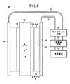
なお、純水や超純水と称されている水や、飲料水として市販されているミネラル水等の不純物量が著しく少ない水は、電気抵抗が1×10⁶Ω・cm以上である絶縁体である。このように電気抵抗が高い液体に対して滅菌処理を施すには、図6に示す滅菌装置30を使用すればよい。
【0050】
この滅菌装置30は、第1電極14と第2電極16との間に介装された陽イオン交換膜32と、第1電極14、第2電極16のそれぞれに電気的に接続された第1給電体34、第2給電体36とを有し、このうち、第2給電体36には通路38が設けられている。
【0051】
なお、第1電極14および第2電極16がリード線22、24を介して直流電源18に電気的に接続されていることや、リード線22、24に定電流回路25およびスイッチング回路20が介装されていること、該スイッチング回路20にオシレータが内蔵されていることについては、上記した滅菌装置10と同様である。
【0052】
陽イオン交換膜32としては、プロトン(H+)を移動させることが可能なプロトン伝導体が選定される。そのような膜の好適な例としては、ナフィオン(商品名、デュポン社製)を挙げることができる。
【0053】
この滅菌装置30にてミネラル水の滅菌処理を行う際には、通路38にミネラル水を流通させる。この状態で、上記に準拠して第1工程および第2工程を繰り返し遂行する。なお、第1電極14および第2電極16への通電は、第1給電体34、第2給電体36の各端面に設置された電極板を介して行われる。
【0054】
この場合、第1工程では、図6に矢印Aとして示すように、第1電極14から第2電極16へ指向して陽イオン交換膜32内をプロトンが移動する。そして、移動してきたプロトンが第2電極16で電子と結合して水素ガスが発生する以前に第2工程が開始される。その結果、矢印Bとして示すように、第2電極16から第1電極14へ指向して陽イオン交換膜32内をプロトンが移動する。勿論、第1電極14でプロトンと電子とが結合して水素ガスが発生する以前に第1工程が再開される。
【0055】
このようにして滅菌処理を施す間、通電が所定時間行われたミネラル水につきサンプルを採取し、該サンプルから培養を行って48時間後の菌類数の計測結果を図5に併せて示す。この図5から、絶縁体であるミネラル水であっても、0.5秒(500ミリ秒)という短時間で菌類の大多数を死滅させることが可能であることが明らかである。
【0056】
ミネラル水が通路38に進入してから導出されるまでの時間、換言すれば、ミネラル水の進路での滞在時間は、0.5秒よりも長時間、例えば、1秒に設定すればよい。
【0057】
このように、本実施の形態によれば、電気抵抗が高い液体に対しても滅菌処理を施すことができる。この場合においても電流の方向を頻繁に反転させるようにしているので、ミネラル水が電気分解を起こす以前に滅菌処理を終了させることができる。
【0058】
しかも、この場合においても、1秒以内という短時間の間に滅菌処理を終了することができる。このため、滅菌処理に要する時間を短縮することができ、食材が流通されるに至るまでの時間を著しく短縮することができる。
【0059】
なお、上記した実施の形態においては、超音波振動子26を振動させるようにしているが、これに代替して、気体によるバブリングを行うようにしてもよい。
【0060】
また、上記から諒解されるように、容器12等の貯留部に貯留された液体に対して通電を行うようにしてもよいし、通路38等の管中を流通される液体に対して通電を行うようにしてもよい。
【0061】
【発明の効果】
以上説明したように、本発明によれば、電流の流れる方向を頻繁に反転させるようにしている。このため、イオン等の電荷が激しく移動するようになり、大きな運動量で菌類に衝突するようになる。これにより菌類を迅速に死滅させることができるので、滅菌処理に要する時間を著しく短縮することができる。この効果は、液体を振動させることによってさらに顕著となる。
【0062】
しかも、この場合、塩素ガス等が発生することを回避することもできるので、滅菌処理された液体や食材に刺激臭が残留することや、食材に変色が生じることを回避することもできる。
【図面の簡単な説明】
【図1】本実施の形態に係る滅菌装置の概略構成図である。
【図2】第1工程および第2工程での各通電時間と、塩素ガスの発生量(溶存量)との関係を示す図表である。
【図3】第1工程および第2工程で通電される電流の波形を示すグラフである。
【図4】一般的な交流電流の波形を示すグラフである。
【図5】本実施の形態に係る滅菌処理が施された様々な液体を採取して培養した48時間後の菌類数の計測結果を示す図表である。
【図6】電気抵抗が高い液体に対して滅菌処理を施すための滅菌装置の概略縦断面図である。
【符号の説明】
10、30…滅菌装置 12…容器
14、16…電極 18…直流電源
20…スイッチング回路 25…定電流回路
26…超音波振動子 32…陽イオン交換膜
34、36…給電体 38…通路[0001]
BACKGROUND OF THE INVENTION
The present invention relates to a sterilization method and an apparatus therefor, and more particularly, to a sterilization method and an apparatus therefor that require significantly less time to sterilize various types of bacteria and viruses.
[0002]
[Prior art]
Foods such as meat, fish and shellfish, vegetables, and fruits are sterilized with an aqueous sodium hypochlorite solution, alcohol, ultraviolet light, ozone, etc. before being shipped to general retail stores or department stores. This drastically reduces the number of pathogenic Escherichia coli such as O-157 and cell-invasive Escherichia coli such as Salmonella, as well as the number of small spherical viruses, astroviruses, rotaviruses, etc., thereby preventing food poisoning. The
[0003]
However, in the sterilization using the sterilizing agent as described above, there is a problem that the odor of the sterilizing agent remains in the food material or the color of the food material changes. Then, when fish shellfish are washed, for example, as proposed in Patent Document 1, it is recalled to obtain seawater that performs bactericidal and antiseptic effects without using a sterilant.
[0004]
[Patent Document 1]
JP 2002-307070 (paragraphs [0021] to [0023])
[0005]
[Problems to be solved by the invention]
By the way, in the method described in Patent Document 1, sterilization is performed by applying a constant voltage to seawater for about 8 to 10 seconds. Regarding this sterilization time, further time reduction is desired.
[0006]
The present invention has been made in connection with the above-described technology, and provides a sterilization method and apparatus having a sterilization ability against various bacteria, bacteria and viruses and having a remarkably short time required for the sterilization treatment. Objective.
[0007]
[Means for Solving the Problems]
To achieve the above object, the present invention is a sterilization method for sterilizing fungi present in a liquid,
A first step of supplying a current flowing from the first electrode to the second electrode between the first electrode and the second electrode in contact with the liquid;
A second step of energizing the current by reversing the direction of the current from the second electrode to the first electrode;
Have
The energization time in the first step and the second step is both 1 second or less. In the present invention, “fungi” is a general term for fungi, bacteria and viruses, and “sterilization” includes killing of bacteria and viruses.
[0008]
Since the direction of current flow is frequently reversed in this way, charges such as ions move violently in the liquid. For this reason, it is assumed that the electric charge collides with the fungus with a large momentum, and as a result, the fungus is quickly killed. This significantly reduces the time required for the sterilization process.
[0009]
The liquid sterilized in this way may be used as a cleaning liquid for foods, etc., or the above first step and second step may be alternately repeated after the foods and affected parts are immersed in the liquid. Good.
[0010]
Preferable examples of the liquid include water containing chlorine ions. Chlorine ions may be obtained, for example, by dissolving NaCl in water. Since this NaCl serves as an electrolyte, the electrical resistance of water is reduced, so that energization in the first step and the second step can be easily performed.
[0011]
In this case, in order to avoid generation of chlorine gas by combining chlorine ions with electrons, it is preferable that both energization times in the first step and the second step be 0.01 seconds or less.
[0012]
According to the present invention, it is possible to sterilize a liquid having an electric resistance of 1 × 10 6 Ω · cm or more, that is, an insulator such as pure water or ultrapure water. In this case, an ion exchange membrane is interposed between the first electrode and the second electrode, and a liquid is circulated or stored in a conductor electrically connected to the first electrode and the second electrode. What is necessary is just to perform a process and a 2nd process.
[0013]
In any case, the current is preferably supplied as a rectangular wave. In this case, since the direction of current flow is rapidly reversed, the charge momentum is larger than when a general alternating current, which is a sine wave, is applied, and thus the fungi are killed in a relatively short time. Because it can.
[0014]
Furthermore, it is preferable to vibrate the liquid during energization. For example, when a sterilization process is performed by immersing the food material in a liquid, the fungi are easily detached from the food material by vibration. For this reason, fungi can be surely killed.
[0015]
Further, the present invention is a sterilization apparatus for sterilizing fungi present in a liquid,
A first electrode and a second electrode in contact with the liquid;
A current supply mechanism comprising a current reversing mechanism for reversing the direction of the current flowing between the first electrode and the second electrode;
It is characterized by having.
[0016]
By adopting such a configuration, it is possible to easily and simply reverse the direction of current flow, and eventually, sterilization can be easily and reliably performed.
[0017]
And an ion exchange membrane interposed between the first electrode and the second electrode; a conductor electrically connected to the first electrode and the second electrode; and a liquid applied to the conductor. It is preferable that a passage for circulation is provided. In this case, a current flows between the first electrode and the second electrode due to the movement of ions through the ion exchange membrane. For this reason, it becomes possible to sterilize the liquid which is an insulator.
[0018]
Note that the current supply mechanism preferably includes a DC power source that supplies a DC current and a switching circuit as a current reversing mechanism. As a result, an alternating current whose waveform is a rectangular wave can be supplied, and eventually the momentum of the electric charge present in the liquid can be increased.
[0019]
And it is preferable to have a vibration member that vibrates the liquid. By performing sterilization while vibrating the liquid with the vibration member, for example, fungi can be easily detached from the food, and the food can be easily and reliably sterilized.
[0020]
DETAILED DESCRIPTION OF THE INVENTION
Hereinafter, preferred embodiments of the sterilization method according to the present invention will be described in detail in relation to an apparatus for performing the method, and will be described in detail with reference to the accompanying drawings.
[0021]
In FIG. 1, the schematic block diagram of the sterilizer which concerns on this Embodiment is shown. The
[0022]
In this case, the
[0023]
The
[0024]
The
[0025]
The switching
[0026]
An
[0027]
Next, the sterilization method according to this embodiment will be described. In this sterilization method, a first step of supplying a current flowing from the
[0028]
First, in the first step, when a direct current is supplied from the direct
[0029]
On the other hand, by energizing the
[0030]
Here, when energized direct current is set voltage value and set current value above a predetermined time elapses, Cl NaCl that was generated by ionization in the tap water W in -
[0031]
In order to avoid the occurrence of such a situation, in the present embodiment, the direction of the current is reversed by the switching
[0032]
Then, before the chlorine gas is generated from the
[0033]
In this way, energization is performed until a predetermined time elapses while avoiding the generation of chlorine gas.
[0034]
FIG. 2 shows the relationship between each energization time in the first step and the second step in this case and the amount of chlorine gas generated when 20 seconds have passed since the first first step was started. From FIG. 2, it can be understood that generation of chlorine gas can be avoided by setting each energization time in the first step and the second step to 0.01 seconds (10 milliseconds). Here, the amount of chlorine gas generated is a value obtained as a dissolved amount in the tap water W.
[0035]
By reversing the direction of the current every 10 milliseconds, the tap water W is supplied with a current having a rectangular waveform as shown in FIG. When such a rectangular wave current is energized, the number of fungi present in the water is drastically reduced as compared to the case where a general alternating current whose waveform is a sine wave as shown in FIG. 4 is energized. . That is, sterilization of water proceeds.
[0036]
Specifically, a sample is collected from the tap water W that has been energized for a predetermined time, cultured from the sample in culture soil, and the number of fungi (unit: CFU) is measured 48 hours later. Thus, in the sample after 0.003 seconds (3 milliseconds), the number of fungi does not increase. This means that there is no fungus capable of growing in the sample after 3 milliseconds after the start of energization, that is, the fungus has been killed in an extremely short time of 3 milliseconds.
[0037]
The tap water W thus sterilized can be used when cleaning foods and food processing equipment. In this case, since there is no need to use a sodium hypochlorite aqueous solution or alcohol, there is an advantage that a chlorine odor or the like does not remain in the food or the food does not change color.
[0038]
Furthermore, since vibration is given to water, the sterilization process proceeds efficiently.
[0039]
Of course, it is also possible to sterilize water in rivers, harbors, lakes, ponds and the like in the same manner.
[0040]
In addition, in this sterilization method, it is possible to kill skin resident bacteria, Legionella bacteria, and the like existing in water. Therefore, the sterilization method can also sterilize hot water used in a circulating bath, a pool, or a Kurhaus that circulates hot water. Of course, in this case as well, there is no need to sterilize with chlorine, ultraviolet rays, ozone, or the like, so hot water having no irritating odor can be used.
[0041]
Furthermore, this sterilization method can also be employed when disinfecting and sterilizing germs that have propagated in affected areas such as burns and trauma. In this case, the affected part may be immersed in a water tank filled with a physiological saline solution having a concentration of about 0.9%, and the above first step and second step may be alternately repeated. Similarly, it is possible to treat skin diseases caused by the propagation of Aspergillus, for example, athlete's foot.
[0042]
FIG. 5 also shows the number of fungi measured in the same manner as above using tap water in which NaCl was dissolved at a concentration of 0.9%, orange juice with 100% fruit juice, and milk as samples. From FIG. 5, it can be seen that the fungi have been killed within 0.1 seconds (100 milliseconds) in all liquids except for mineral water described later.
[0043]
Thus, according to the sterilization method according to the present embodiment, a sterilization process can be performed even for liquids other than tap water W. Of course, it is possible to sterilize beer, soy sauce, sauce, and the like.
[0044]
In particular, in the sake brewing process and soy sauce manufacturing process, if germs are mixed in, the growth of yeasts and koji molds decreases and the production efficiency decreases. In this case, manufacturing efficiency can be improved by selectively sterilizing various bacteria.
[0045]
In addition, what is necessary is just to set an electric current value and energization time suitably, in order to selectively sterilize various germs. For example, the current and energization time required to kill bacteria having cell membranes are smaller than the current and energization time required to kill gonococci having cell walls. Therefore, selective sterilization can be performed by setting the set current value and the energization time to a condition that is sufficient for killing bacteria having cell membranes and not killing gonococci having cell walls. .
[0046]
When sterilizing foods such as meat, fish and shellfish, vegetables, fruits, etc., the first step and the second step may be repeatedly performed on the water after the food is immersed in water. At this time, since the
[0047]
That is, by applying vibration, sterilization of food can be more reliably performed.
[0048]
Thus, according to the sterilization method according to the present embodiment, the sterilization process can be completed in an extremely short time of 100 milliseconds or less. The reason for this is that, as the direction of current flow is frequently reversed, the charges such as ions move violently in the liquid, and finally the violently moving charges collide with fungi with a large momentum. This is presumed to be due to this.
[0049]
In addition, water with a very small amount of impurities, such as pure water or ultrapure water, or mineral water commercially available as drinking water, has an electrical resistance of 1 × 10 6 Ω · cm or more. It is. In order to sterilize the liquid having such a high electrical resistance, a
[0050]
The
[0051]
The
[0052]
As the
[0053]
When sterilizing mineral water with this
[0054]
In this case, in the first step, as indicated by an arrow A in FIG. 6, protons move in the
[0055]
During the sterilization process in this way, a sample is collected from the mineral water that has been energized for a predetermined time, and the result of counting the number of fungi after 48 hours from the sample is shown in FIG. From FIG. 5, it is clear that even the mineral water that is an insulator can kill the majority of fungi in a short time of 0.5 seconds (500 milliseconds).
[0056]
The time from when mineral water enters the
[0057]
Thus, according to the present embodiment, it is possible to sterilize even a liquid having a high electrical resistance. Even in this case, since the direction of the current is frequently reversed, the sterilization process can be terminated before the mineral water undergoes electrolysis.
[0058]
Moreover, even in this case, the sterilization process can be completed within a short time of 1 second or less. For this reason, the time required for the sterilization treatment can be shortened, and the time until the food is distributed can be remarkably shortened.
[0059]
In the above-described embodiment, the
[0060]
Further, as understood from the above, the liquid stored in the storage part such as the
[0061]
【The invention's effect】
As described above, according to the present invention, the direction of current flow is frequently reversed. For this reason, electric charges such as ions move violently and collide with fungi with a large momentum. As a result, the fungi can be quickly killed, and the time required for the sterilization treatment can be significantly shortened. This effect becomes more remarkable by vibrating the liquid.
[0062]
In addition, in this case, generation of chlorine gas or the like can be avoided, so that the irritating odor remains in the sterilized liquid or food material, or the food material can be prevented from being discolored.
[Brief description of the drawings]
FIG. 1 is a schematic configuration diagram of a sterilization apparatus according to an embodiment.
FIG. 2 is a chart showing the relationship between each energization time in the first step and the second step and the amount of chlorine gas generated (dissolved amount).
FIG. 3 is a graph showing waveforms of currents applied in the first step and the second step.
FIG. 4 is a graph showing a general alternating current waveform;
FIG. 5 is a chart showing the measurement results of the number of fungi 48 hours after collecting and culturing various liquids that have been sterilized according to the present embodiment.
FIG. 6 is a schematic longitudinal sectional view of a sterilization apparatus for performing a sterilization process on a liquid having a high electrical resistance.
[Explanation of symbols]
DESCRIPTION OF
Claims (6)
前記液体に接触する第1電極および第2電極の間に、前記第1電極から前記第2電極に指向して流れる電流を供給する第1工程と、
前記電流の方向を前記第2電極から前記第1電極に反転させて通電する第2工程と、
を有し、
前記液体が絶縁体であり、イオン交換膜を介装する前記第1電極と前記第2電極に電気的に接続された導電体に前記液体を流通または貯留し、
前記第1工程および前記第2工程における通電時間をともに1秒以下とすることを特徴とする滅菌方法。A sterilization method for sterilizing fungi present in a liquid,
A first step of supplying a current flowing from the first electrode to the second electrode between the first electrode and the second electrode in contact with the liquid;
A second step of energizing the current by reversing the direction of the current from the second electrode to the first electrode;
Have
The liquid is an insulator, and the liquid is circulated or stored in a conductor that is electrically connected to the first electrode and the second electrode that interpose an ion exchange membrane,
The sterilization method characterized in that both energization times in the first step and the second step are 1 second or less.
前記液体に接触する第1電極および第2電極と、
前記第1電極と前記第2電極との間に流れる電流の方向を反転させる電流反転機構を具備する電流供給機構と、
前記第1電極と前記第2電極に介装されたイオン交換膜と、
前記第1電極と前記第2電極に電気的に接続された導電体と、
を有し、
前記導電体に前記液体を流通させる通路が設けられていることを特徴とする滅菌装置。A sterilizer for sterilizing fungi present in a liquid,
A first electrode and a second electrode in contact with the liquid;
A current supply mechanism comprising a current reversing mechanism for reversing the direction of the current flowing between the first electrode and the second electrode;
An ion exchange membrane interposed between the first electrode and the second electrode;
A conductor electrically connected to the first electrode and the second electrode;
I have a,
Sterilization apparatus according to claim that you have passages for flowing is provided the liquid to the conductor.
Priority Applications (1)
| Application Number | Priority Date | Filing Date | Title |
|---|---|---|---|
| JP2003047777A JP4139877B2 (en) | 2003-02-25 | 2003-02-25 | Sterilization method and apparatus |
Applications Claiming Priority (1)
| Application Number | Priority Date | Filing Date | Title |
|---|---|---|---|
| JP2003047777A JP4139877B2 (en) | 2003-02-25 | 2003-02-25 | Sterilization method and apparatus |
Publications (2)
| Publication Number | Publication Date |
|---|---|
| JP2004255271A JP2004255271A (en) | 2004-09-16 |
| JP4139877B2 true JP4139877B2 (en) | 2008-08-27 |
Family
ID=33113938
Family Applications (1)
| Application Number | Title | Priority Date | Filing Date |
|---|---|---|---|
| JP2003047777A Expired - Lifetime JP4139877B2 (en) | 2003-02-25 | 2003-02-25 | Sterilization method and apparatus |
Country Status (1)
| Country | Link |
|---|---|
| JP (1) | JP4139877B2 (en) |
Families Citing this family (1)
| Publication number | Priority date | Publication date | Assignee | Title |
|---|---|---|---|---|
| KR20100131351A (en) * | 2009-06-05 | 2010-12-15 | 한국돌기 주식회사 | Manufacturing method of medical sterilized isotonic solution having low-concentratedly controlled free chlorine including hypochlorous acid therein |
-
2003
- 2003-02-25 JP JP2003047777A patent/JP4139877B2/en not_active Expired - Lifetime
Also Published As
| Publication number | Publication date |
|---|---|
| JP2004255271A (en) | 2004-09-16 |
Similar Documents
| Publication | Publication Date | Title |
|---|---|---|
| JP2001276828A (en) | Electrolytically sterilizing method of water and electrolytically sterilizing device therefor | |
| US20040037737A1 (en) | Method of and equipment for washing, disinfecting and/or sterilizing health care devices | |
| US8062501B2 (en) | Neutral electrolytic water, neutral electrolytic water production method and device thereof | |
| JP4723647B2 (en) | Electrolytic disinfection device for marine ballast water | |
| JP4410155B2 (en) | Electrolyzed water ejection device | |
| US20050244556A1 (en) | Electrolyzed water treatment for meat and hide | |
| JPH10151464A (en) | Drinking water supplying apparatus | |
| KR100567750B1 (en) | Activated water apparatus and methods | |
| KR20110072445A (en) | Method of sterilizing and cleaning medical device satisfying high level disinfection and apparatus using same | |
| CN204813428U (en) | High -voltage pulse electric field sterilization water dispenser | |
| JPH0628566B2 (en) | Liquid Food Sterilization Method | |
| KR101248571B1 (en) | Complex electrolysis apparatus for sterilization and disinfection | |
| KR20130000043A (en) | Method of sterilizing and cleaning medical device satisfying high level disinfection and apparatus using same | |
| KR100789325B1 (en) | Manufacturing apparatus of sterilized water with high portion of hypochlorous acid | |
| JP4139877B2 (en) | Sterilization method and apparatus | |
| JP3349810B2 (en) | Apparatus and method for sterilizing food and maintaining freshness | |
| JP2003034889A (en) | Method for electrolysis in device for generating strong- electrolyzed water | |
| JP2003190954A (en) | Method for sterilizing seawater and apparatus therefor | |
| KR20100095272A (en) | Manufacturing method of non-harmful sterilizant to human for medical device or grain or vegetables | |
| JPH1119648A (en) | Sterilizing device | |
| JP2007090333A (en) | Method for treating salt water | |
| KR101036181B1 (en) | Apparatus for ship ballast water using electrolysis | |
| JP5172098B2 (en) | Air sanitizer | |
| JP3962601B2 (en) | Method and apparatus for producing disease control liquid for agricultural products | |
| KR101954690B1 (en) | Sterilizer for medical appliances or processed food |
Legal Events
| Date | Code | Title | Description |
|---|---|---|---|
| A621 | Written request for application examination |
Free format text: JAPANESE INTERMEDIATE CODE: A621 Effective date: 20060223 |
|
| A977 | Report on retrieval |
Free format text: JAPANESE INTERMEDIATE CODE: A971007 Effective date: 20080118 |
|
| A131 | Notification of reasons for refusal |
Free format text: JAPANESE INTERMEDIATE CODE: A131 Effective date: 20080122 |
|
| A521 | Request for written amendment filed |
Free format text: JAPANESE INTERMEDIATE CODE: A523 Effective date: 20080321 |
|
| TRDD | Decision of grant or rejection written | ||
| A01 | Written decision to grant a patent or to grant a registration (utility model) |
Free format text: JAPANESE INTERMEDIATE CODE: A01 Effective date: 20080415 |
|
| A01 | Written decision to grant a patent or to grant a registration (utility model) |
Free format text: JAPANESE INTERMEDIATE CODE: A01 |
|
| A521 | Request for written amendment filed |
Free format text: JAPANESE INTERMEDIATE CODE: A523 Effective date: 20080514 |
|
| A711 | Notification of change in applicant |
Free format text: JAPANESE INTERMEDIATE CODE: A711 Effective date: 20080514 |
|
| A61 | First payment of annual fees (during grant procedure) |
Free format text: JAPANESE INTERMEDIATE CODE: A61 Effective date: 20080514 |
|
| A521 | Request for written amendment filed |
Free format text: JAPANESE INTERMEDIATE CODE: A821 Effective date: 20080514 |
|
| FPAY | Renewal fee payment (event date is renewal date of database) |
Free format text: PAYMENT UNTIL: 20110620 Year of fee payment: 3 |
|
| R150 | Certificate of patent or registration of utility model |
Free format text: JAPANESE INTERMEDIATE CODE: R150 Ref document number: 4139877 Country of ref document: JP Free format text: JAPANESE INTERMEDIATE CODE: R150 |
|
| FPAY | Renewal fee payment (event date is renewal date of database) |
Free format text: PAYMENT UNTIL: 20120620 Year of fee payment: 4 |
|
| R250 | Receipt of annual fees |
Free format text: JAPANESE INTERMEDIATE CODE: R250 |
|
| FPAY | Renewal fee payment (event date is renewal date of database) |
Free format text: PAYMENT UNTIL: 20130620 Year of fee payment: 5 |
|
| R250 | Receipt of annual fees |
Free format text: JAPANESE INTERMEDIATE CODE: R250 |
|
| FPAY | Renewal fee payment (event date is renewal date of database) |
Free format text: PAYMENT UNTIL: 20140620 Year of fee payment: 6 |
|
| R250 | Receipt of annual fees |
Free format text: JAPANESE INTERMEDIATE CODE: R250 |
|
| R250 | Receipt of annual fees |
Free format text: JAPANESE INTERMEDIATE CODE: R250 |
|
| R250 | Receipt of annual fees |
Free format text: JAPANESE INTERMEDIATE CODE: R250 |
|
| R250 | Receipt of annual fees |
Free format text: JAPANESE INTERMEDIATE CODE: R250 |
|
| R250 | Receipt of annual fees |
Free format text: JAPANESE INTERMEDIATE CODE: R250 |
|
| R250 | Receipt of annual fees |
Free format text: JAPANESE INTERMEDIATE CODE: R250 |
|
| R250 | Receipt of annual fees |
Free format text: JAPANESE INTERMEDIATE CODE: R250 |
|
| R250 | Receipt of annual fees |
Free format text: JAPANESE INTERMEDIATE CODE: R250 |
|
| R250 | Receipt of annual fees |
Free format text: JAPANESE INTERMEDIATE CODE: R250 |
|
| R250 | Receipt of annual fees |
Free format text: JAPANESE INTERMEDIATE CODE: R250 |
|
| EXPY | Cancellation because of completion of term |