JP4139436B2 - Gravity compensated accelerometer and method of manufacturing the same - Google Patents
Gravity compensated accelerometer and method of manufacturing the same Download PDFInfo
- Publication number
- JP4139436B2 JP4139436B2 JP50271897A JP50271897A JP4139436B2 JP 4139436 B2 JP4139436 B2 JP 4139436B2 JP 50271897 A JP50271897 A JP 50271897A JP 50271897 A JP50271897 A JP 50271897A JP 4139436 B2 JP4139436 B2 JP 4139436B2
- Authority
- JP
- Japan
- Prior art keywords
- seismic mass
- force
- gravity
- accelerometer
- stress
- Prior art date
- Legal status (The legal status is an assumption and is not a legal conclusion. Google has not performed a legal analysis and makes no representation as to the accuracy of the status listed.)
- Expired - Fee Related
Links
Images


Classifications
-
- G—PHYSICS
- G01—MEASURING; TESTING
- G01P—MEASURING LINEAR OR ANGULAR SPEED, ACCELERATION, DECELERATION, OR SHOCK; INDICATING PRESENCE, ABSENCE, OR DIRECTION, OF MOVEMENT
- G01P15/00—Measuring acceleration; Measuring deceleration; Measuring shock, i.e. sudden change of acceleration
- G01P15/02—Measuring acceleration; Measuring deceleration; Measuring shock, i.e. sudden change of acceleration by making use of inertia forces using solid seismic masses
- G01P15/08—Measuring acceleration; Measuring deceleration; Measuring shock, i.e. sudden change of acceleration by making use of inertia forces using solid seismic masses with conversion into electric or magnetic values
- G01P15/0802—Details
-
- G—PHYSICS
- G01—MEASURING; TESTING
- G01P—MEASURING LINEAR OR ANGULAR SPEED, ACCELERATION, DECELERATION, OR SHOCK; INDICATING PRESENCE, ABSENCE, OR DIRECTION, OF MOVEMENT
- G01P15/00—Measuring acceleration; Measuring deceleration; Measuring shock, i.e. sudden change of acceleration
- G01P15/02—Measuring acceleration; Measuring deceleration; Measuring shock, i.e. sudden change of acceleration by making use of inertia forces using solid seismic masses
- G01P15/08—Measuring acceleration; Measuring deceleration; Measuring shock, i.e. sudden change of acceleration by making use of inertia forces using solid seismic masses with conversion into electric or magnetic values
- G01P2015/0805—Measuring acceleration; Measuring deceleration; Measuring shock, i.e. sudden change of acceleration by making use of inertia forces using solid seismic masses with conversion into electric or magnetic values being provided with a particular type of spring-mass-system for defining the displacement of a seismic mass due to an external acceleration
- G01P2015/0822—Measuring acceleration; Measuring deceleration; Measuring shock, i.e. sudden change of acceleration by making use of inertia forces using solid seismic masses with conversion into electric or magnetic values being provided with a particular type of spring-mass-system for defining the displacement of a seismic mass due to an external acceleration for defining out-of-plane movement of the mass
- G01P2015/0825—Measuring acceleration; Measuring deceleration; Measuring shock, i.e. sudden change of acceleration by making use of inertia forces using solid seismic masses with conversion into electric or magnetic values being provided with a particular type of spring-mass-system for defining the displacement of a seismic mass due to an external acceleration for defining out-of-plane movement of the mass for one single degree of freedom of movement of the mass
- G01P2015/0828—Measuring acceleration; Measuring deceleration; Measuring shock, i.e. sudden change of acceleration by making use of inertia forces using solid seismic masses with conversion into electric or magnetic values being provided with a particular type of spring-mass-system for defining the displacement of a seismic mass due to an external acceleration for defining out-of-plane movement of the mass for one single degree of freedom of movement of the mass the mass being of the paddle type being suspended at one of its longitudinal ends
Description
【技術分野】
【0001】
本発明は、重力補償型加速度計に関する。加速度計のサイズモ質量体(マス)に対する重力の影響を補償することによって、加速度の変化に対する加速度計の感度を向上することができる。
【0002】
本発明は特に小型の装置に適用される。この性質が、この加速度計を機械技術、超小型機械技術、または超小型電子技術(例えばマイクロマシニング)による製造に適したものにしている。
【0003】
本発明による加速度計の主な適用分野は、重力を受ける環境の動きまたは挙動の研究(例えば地震学)にある。
【0004】
したがって本発明は、従来の技術による単体型加速度計ではなし得なかった、重力補償単体型加速度計の設計を可能にするものである。従来の技術によるこの種の加速度計は、例えばM.「Development of micromachined silicon accelerometer(超小型機械加工されたシリコン加速度計の開発)」、Sumitomo Electric Technical Review,No.38号,1994年6月,pp.72− 77、及びMichael E.Hoenkの論文「Small inertial measurements units − sources of error and limitations on accuracy(小型慣性測定装置−エラー源と精度の限界)」SPIE,Vol.2220,pp.15−26に記載されている。
【背景技術】
【0005】
加速度を測定するために使用される最も普遍的な方法は、加速度自体を直接に測定するのではなく、問題とする加速度γの影響により質量Mにかかる力Fを測定することから成る。運動の基本法則F=M・γによれば、Mの値がわかっている場合には、Fを測定して加速度の値を得ることができる。
【0006】
したがって、最も普遍的な型の加速度センサは、一般に一つまたは複数のばねによって支持されている慣性質量すなわちサイズモ質量体から構成される。この質量は加速度の変化を受けると、変位してばねが変形する。加速度によって生じる力が無くなると、すぐにシステムは最初の位置に戻る。
【0007】
静止状態では、水平加速度センサはいかなる妨害力にも感応しない。これに対して、垂直受感軸加速時計は重力による力と同等の最小力、F=M・gを受ける。ただしgは重力定数である。
【0008】
この重力による最小力は、非常に小さな垂直加速度(10-6G以下)を測定しようとする場合には不都合である。したがってこの場合には、重力による力を、重力とは反対の方向に向いた力によって補償することが重要である。今日、重力を補償する方法は下記の二つに類別される。すなわち、
− 電気エネルギー源を使用する方法。電磁界または静電界でサイズモ質量体を懸架状態に維持する。この方法は複雑なサーボシステムを必要とする。
− ばねの復元力を使用する方法。予め変形されたばねによって質量を懸架された状態で平衡に保つ。
【0009】
また、静電力または電磁力とばねの復元力を同時に使用する、ハイブリッドシステムも存在する。このようなシステムは、例えばShi Jung ChenとKuan Chenの論文「The effects of spring and magnetic distortions on electromagnetic geophones(電磁ジオフォンに対するばねと磁気ひずみの影響)」(J.Phys.E: Sci.Instrum.pp.21(1988),pp.943−947)に記載されている。
【0010】
これらの技術は別の不都合がある。
【0011】
静電装置または電磁装置の場合には、電子サーボシステムの存在は、所望の感度とは両立しない妨害ノイズを発生させる可能性がある。その上、単なる静電補償ではシステムの不安定性を招き、これはサーボ制御を困難にする。
【0012】
サイズモ質量体に対する重力の影響をばねによって補償する垂直受感軸センサは、現在様々な機械部品を組み合わせて作られている。このようなセンサは、例えばE.WielandtとG.Streckeisenの論文「The leaf spring seismometer: design and performance(板ばね式地震計の設計と性能)」(Bulletin of Seismological Society of America、Vol.72,No.6,pp.2349−2367、1982年12月)に記載されている。この形式の装置は、その構造上非常に高いQ因子を持たない。この構造パラメータは、下記の関係式による装置のブラウンノイズの密度Sに関係する。
【数1】
ωγは共振脈動、
kbはボルツマン定数、
Tは温度、
Mはサイズモ質量体である。
【0013】
この関係式についてさらに詳しくは、Hoenkの前掲論文を参照されたい。この関係式は、SがQ及びMに反比例することを示す。
【0014】
ブラウンノイズを測定の妨害とならないレベルに保持するために、現在の装置は大きな質量Mを持っている。しかしながら、この解決法では組立品の小型化が制限される。したがって、最も小型の高性能装置(例えば、1G以下の数ナノGの変化を検出できるもの)の重さは数キログラムであり、容積は数10cm3である。
【0015】
結局、現在の垂直軸加速度計は、感度が低いかまたは重くてかさばるものである。高性能装置の小型化には、サイズモ質量体Mを減らすこと、したがってQの増加が要求される。これは、例えば単結晶シリコンのように高いQを有する材料のセンサの組立品(ばねによる重力補償の場合にはサイズモ質量体とばね)を使用することによって得ることができる。しかしながら、サイズモ質量体に固定されたばねを含むコンパクトな装置の製造には、技術的な困難がある。実際に、内部摩擦が大きくてQに有害な減衰現象を引き起こす領域を作り出すことなく、ねじなどの機械的手段または接着剤によって、ばねやサイズモ質量体などの小さな機械部品を固定することは困難である。さらに、ばねには高い柔軟性を保持させることが必要で、この柔軟性はセンサの感度に影響するものである。
【発明の開示】
【発明が解決しようとする課題】
【0016】
本発明が提案する重力補償技法は、ばねによって支えられたサイズモ質量体を有するセンサ群に属する。この解決法には、他の装置に必要なサーボシステムによって発生する妨害ノイズを減らすという利点がある。この補償技法は、サイズモ質量体を支える構成部分(例えばビーム)の表面にプレストレスを与えることによって形成される板ばねの原理に基づく。
【課題を解決するための手段】
【0017】
したがって本発明は、測定すべき加速度によって引起される力を受けることのできるサイズモ質量体を含み、サイズモ質量体は前記力の影響下で曲がることのできる機械的連結手段によって支持体に連結され、サイズモ質量体に引起された力から加速度を決定することができる検出手段が設けられ、重力によってサイズモ質量体にかかる力を補償するための補償手段が設けられる加速度計であって、機械的連結手段は、この機械的連結手段中に重力によってサイズモ質量体にかかる力に対抗するプレストレスを引起すことにより、前記補償手段を構成する少なくとも一つの部分を含むことを特徴とする、加速度計を対象とする。
【0018】
重力によってサイズモ質量体にかかる力を補償する手段は、機械的連結手段上に付着された表面層によって構成することができ、この表面層は、サイズモ質量体に対して重力によってかけられる力に対抗するように、機械的連結手段の片面に形成されており、前記機械的連結手段に対して応力をかけるために必要な特性を有する材料から成っている。
【0019】
この場合、前記応力をかける材料は、クロム、モリブデン、タングステン、これらの合金の一つ、またはPZT型セラミックからなる群中から選ぶことができる。
【0020】
重力によってサイズモ質量体にかかる力を補償する手段は、機械的連結手段が備えている二つの表面層によって構成することができ、これらの表面層は機械的連結手段の対向する二つの面上に形成され、表面層の一方は引張り応力を引起す材料でできており、他方は圧縮応力を引起し、これらの二つの表面層の組合せが、機械的連結手段の厚み中に応力勾配を引起し、この応力勾配が重力によってサイズモ質量体にかかる力に対抗する。
【0021】
この場合、二つの表面層は、逆の符号を有する応力を与えるように、異なる技術によって付着されたモリブデンの薄層で構成することができる。
【0022】
他の一変形実施例によれば、重力によってサイズモ質量体にかかる力を補償する手段は、機械的連結手段中に前記プレストレスを引起す、機械的連結手段の表面の改質によって構成することができる。
【0023】
この表面の改質は、機械的連結手段を構成する材料の表面をドープすることによるのが有利である。
【0024】
この場合、機械的連結手段は単結晶シリコンでできており、機械的連結手段の面の一方を、リン、ホウ素、キセノン、チタン、ヒ素、及びアルゴンから成る群中から選ばれたドーピング剤によってドープすることができる。
【0025】
機械的連結手段の対向する二つの面に表面ドーピングを行うことができ、これらの面の各々は異なったドーピング剤によってドープされ、これらのドーピング剤の一方は引張り応力を引起し、他方は圧縮応力を引起し、これらの組合せの結果、機械的連結手段の厚み中に、重力によってサイズモ質量体にかかる力に対抗する応力勾配を引起すことになる。
【0026】
機械的連結手段がシリコンでできている場合には、機械的連結手段の面の一方をホウ素によってドープし、他方をアルゴンによってドープすることができる。
【0027】
機械的連結手段は、一つまたは複数のビームによって構成することができる。
【0028】
このような設計によって、サイズモ質量体、機械的連結手段、及び単体組立品としての支持体を実現することができる。こうして、周知の技術による単体形式の加速度計とは異なり、本発明によって単体形式の重力補償加速度計を得ることが可能になる。
【0029】
したがって本発明はまた、測定すべき加速度によってサイズモ質量体中に引起された力の影響の下で曲がることができる機械的連結手段によって支持体に連結されたサイズモ質量体を含み、重力によってサイズモ質量体にかかる力を補償するための補償手段が設けられている加速度計の製造方法をも対象としており、この方法は、
− サイズモ質量体と支持体を画定するために、基板の主要面の一つ、すなわち第一面をマスクするステップ、
− 第一面から、反対の主要面すなわち第二面の方向にエッチングの底部と第二面の間に薄膜が残るまで基板をエッチングして、エッチングによりサイズモ質量体と支持体を画定するステップ、
− 支持体、サイズモ質量体、及び機械的連結手段をマスクするために、基板の第二面をマスクするステップ、
− 薄膜のマスクされていない部分を開口させるために、基板を第二面からエッチングするステップ、及び
− 重力によってサイズモ質量体にかかる力に対抗するプレストレスを引起し、前記補償手段を構成するために、機械的連結手段の少なくとも一部分を表面処理するステップを含むことを特徴とする。
【0030】
添付の図面を参照して非限定的な例として示す以下の説明によって、本発明がよりよく記述され、本発明の他の利点と特徴がさらに明らかになろう。
【0031】
次に、サイズモ質量体を含む加速度計について説明する。このサイズモ質量体は、これを支持体に機械的に連結する要素から区別され、この連結要素は一つまたは複数のビームによって構成することができる。このことは本発明を限定するものではなく、本発明は、サイズモ質量体がビームと区別されていない、すなわちビームと一体となっている場合にも適用される。
【発明を実施するための最良の形態】
【0032】
図1は、本発明の原理を垂直受感軸加速度計について概略的に示した図である。この図には、一本のビーム3によって支持体2に連結された質量Mを有するサイズモ質量体1が示されている。したがって、サイズモ質量体1は支持体2に対して不安定に置かれている。ビーム3の質量を無視すると、サイズモ質量体1の重心は、加速度gに従ってサイズモ質量体にかかる力Fの作用を受ける。
【0033】
サイズモ質量体1に対する重力の影響を補償するために、ビーム3の上部表面4を、プレストレスを引起するように処理する。このプレストレスの結果、サイズモ質量体に重力によって引起される力を補償する力がこのサイズモ質量体にかかるようになる。
【0034】
ビームのこの表面応力付与は種々の方法で得ることができる。これは、ビームの表面に薄膜を付着するか、または応力効果を生成させるために十分にビームの表面を改質することによって得ることができる。こうして処理されると、ビームは曲がる傾向を有するようになり、重力による力に対抗する力をかける。応力付与の条件は、図1の曲線矢印で示すように、ビームの端部が上向きの補償力をかけるようにしなければならない。応力が十分に強い場合には、この抵抗力は重力による力と平衡するのに十分である。
【0035】
ビームの上に層を付着する場合には、使用できる付着材料は、金属またはその合金中から、あるいは例えばPZTとも呼ばれ化学式Pb(ZrxTi1−x)O3で示されるセラミックのようなある種の誘電材料など、応力を出すことが知られる材料中から選ぶことができる。クロム、モリブデン、タングステン、またはこれらの合金の一つを使用することが好ましい。
【0036】
ビームの改質は、ビーム自体を構成する材料の表面域を改質するために適当な方法を使用することを意味する。この方法は、ビームの表面をわずかな厚さでドープすることでもよい。この場合には、ビームのドープした部分とドープしない部分との間でバイメタル効果が得られるように、ビームを構成する材料に応じてドーピング剤を選択するのが有利である。ビームが単結晶シリコンでできている場合には、次の元素、すなわちリン、ホウ素、キセノン、チタン、ヒ素、アルゴン中から選ばれたドーピング剤を使用することができる。
【0037】
したがって、本発明によって提案される解決法は、別の要素で作られた機械的連結手段を利用することなしに、小さな寸法にすることのできる組立品を形成する、サイズモ質量体に連結されたばねの設計が可能である。
【0038】
図1は、最も簡単なバージョン、すなわちビームを一つだけ含む加速度計を示す。しかし本発明は多くのビームを有する加速度計にも適用される。
【0039】
本発明は、(並進運動及び重心の周りの回転運動における)サイズモ質量体の自由度を垂直移動に制限するために、二、四、または八本のビームを有する加速度計に適用することもできる。したがって、これらのビームは場合に応じて二本ずつまたは四本ずつに対向して配置される。
【0040】
図2は、この形式の加速度計を示す。サイズモ質量体10は支持体11に連結されており、支持体11は、図を単純化するために二本ずつ対向して配置された四本のビーム12によってサイズモ質量体のレベルで平坦になっている。重力によって生じサイズモ質量体10にその作用をかける力を補償するために、四本のビーム12並びにサイズモ質量体10を被覆する適当な表面層13が付着された。
【0041】
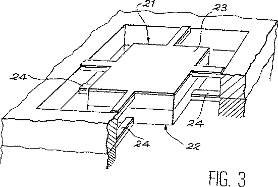
図3は、図2と同じ図示様式で、八本のビームを有する加速度計を示す。この加速度計は、各々四本のビーム(すなわち各々が図2に示された形式のビーム)を含む二つの構造21、22の接着によって得ることができる。この接着は、例えばO.Zucker、W.Langheinrich、M.kulozik及びH.Guebelの論文「Application of oxygen plasma processing to silicon direct bonding(シリコン直接接着への酸素プラズマ法の適用)」(La revue Sensors and Actuators A.36,1993,pp.227−231)に記載の、周知の接着法または固着法によって行うことができる。表面層は重力を補償するためにその作用をかけなければならないので、これらの表面層23、24は、加速度計が組み立てられた後にビームの最上部になる表面に取り付けられる。
【0042】
ビームの表面に付着された薄層によってかけられる平面応力は、第一変形の方向に垂直に、ビームの横断変形をも引起す。その結果生ずる輪郭は、ビームの慣性モーメントを、したがってセンサの感度に影響するシステムの剛性を際立たせる。この現象が過度に妨害になると考えられる場合には、多くの方法で矯正することができる。
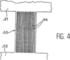
【0043】
第一の解決法は、本発明による加速度計の部分上面図である図4に示すような、ビームの上に断続的な層を付着することから成る。サイズモ質量体31はビーム33によって支持体32に連結されていることを確認されたい。ビーム33の上面は、連続層によってではなく、サイズモ質量体と支持体32との間に配向された平行な線34によって被覆されている。この形状では、付着された薄層は線に垂直に作用する応力から構成部分を部分的に緩和しようとする。この点について詳しくは、L.Maniguet、M.Ignat、M.Dupeux、J.J.Bacmann、及びP.Normandonの論文「Analyse par diffraction des rayons X,de l’evolution des contraintes residuelles associee a la gravure de lignes dans un depot mince de tungstene CVD sur substrat de Si(Si基板上のCVDタングステン薄層にエッチングされた線に伴う残留応力発生のX線回折による解析)」、La Revue de Metallurgie−CIT/Science et Genie des Materiaux,1993年9月、pp.1109を参照されたい。
【0044】
第二の解決法は、最大応力を最も好ましい方向に、すなわちサイズモ質量体と支持体との間に向けるために、いくつかの薄い金属膜における応力の固有異方性を利用することから成る。この応力固有異方性現象は、特にP.Gergaud及びJ.J.Bacmannの論文「Internal stress tensor determination in molybdenum and molybdenum−carbon thin films deposited by D.C.magnetron sputtering(直流マグネトロンスパッタリングによって蒸着されたモリブデン及びモリブデン炭素の薄膜における内部応力テンソルの決定)」、La revue Materials Science Forum,Vol.133−136、1993年,pp.873−878に記載されている。
【0045】
これらの二つの解決法を同時に実施することによって、これらの現象を合併することができ、またある場合には横断応力を除去することができる。
【0046】
第3の解決法は、ビーム中に、サイズモ質量体から支持体に向かう方向を有する1本または複数本の縦スリットを設けることから成る。重力補償手段がビームの上に付着された表面層によって構成されている場合には、この層は、図4に示すものに似たパターンで好ましくは厚み全体にわたるスリットである。
【0047】
表面応力は、付着によって、またはビームの厚み中に応力勾配を作り出す処理によって行使させることができる。薄膜の使用によって、二層システム、すなわち図1を参照すると、一つの薄膜4と一つの薄膜5とがそれぞれビームの対向する各面に付着されたものの設計が可能になる。上部薄膜は引張り応力を加え、また下部薄膜は圧縮応力を加える。加工条件に従って逆符号の応力を示す薄膜用材料(例えばモリブデン)もある。D.W.Hoffman及びJ.A.Thorntonの論文「Internal stresses in sputtered chromium(スパッタリングによって付着されたクロムにおける内部応力)」,Thin Solid Films,40(1997),pp.355−363は、クロムの場合におけるこの現象を記載している。
【0048】
さらに、超小型電子技術の分野では、注入される元素の性質と注入条件に応じて圧縮応力または引張り応力を得ることが可能な、ドーピング技法がある。これは、R.Fabbri、M.Servidori、及びA.Zaniによる論文「Parallel stress and perpendicular strain depth distribution in[001]silicon amorphized by ion implantation(イオン注入によって無定形化された[001]ケイ素における平行応力と垂直応力の深さの分布)」,La revue J.Appl.Phys.66(10),1989年11月15日,pp.4715−4718で論じられている。例えば、ホウ素によるドーピングはケイ素中に引張り応力を発生させるが、アルゴンによるドーピングは同じ元素中に圧縮応力を発生させる。
【0049】
上部薄層を形成するために使用される(そして引張り力を加える)材料が、下部薄層を形成するために使用され(そして圧縮力を加える)材料と同じ場合には、これらの薄層各々の熱膨脹率は非常に近いどころか同一であり、このためシステムは温度に感応しない。薄層をビームの対向する両面に付着する場合には、モリブデンを使用することが好ましい。ビームを構成する材料(例えばケイ素)をドープすることによって薄層を作る場合には、各面のドーピング剤が異なっていても、ドーピング剤を受ける基板材料が同じである以上、各層の熱膨脹率はほとんど違わない。
【0050】
ここで、本発明による加速度計の一実施例を述べることにする。選んだのは、超小型電子技術を利用した、図2に示す形式の四ビーム式加速度計の実施例である。このセンサは<100>配向ケイ素によって作られている。化学洗浄をした後に、ケイ素を、窒化ケイ素Si3N4の層でもよいマスクで覆う。通常の写真製版法を用いて、サイズモ質量体を画定するゾーンの開口部をマスク中に作成する。それからケイ素の異方性エッチングを、例えば苛性カリKOH浴中で行う(例えば、ウエダ等の前掲論文を参照のこと)。エッチング時間は、サイズモ質量体の周りに薄いケイ素の膜ができるのに十分な長さにする。
【0051】
図5は、製造方法のこの段階を終わって得られた結果を示す。この図では、出発基板40が断面で示されている。この断面はサイズモ質量体41を通り、サイズモ質量体41の周りに残る膜42の厚さの見当を示す。
【0052】
次いで、膜の側に位置する基板40の面43を、酸化ケイ素SiO2の層で覆う。上述と同様に、ビームの側部とサイズモ質量体の周囲を画定するように、この被覆を開く。次に、三塩化ホウ素BCl3と塩素Cl2の混合気体中における物理的エッチング技法(プラズマエッチング)によって、マスクされていない膜のケイ素を除去することができる。この作業の後、サイズモ質量体は構造から解放され、ビームのみによって支持される。残りの酸化ケイ素の層は、トリフルオロメタンCHF3と酸素O2の混合気体中でプラズマエッチングによって除去される。
【0053】
次いで、マグネトロン陰極スパッタリングによって薄板上に応力薄膜を付着する。(モリブデン製の)金属膜を形成するためのパラメータを調節して、材料中に引張り応力を生成する。
【0054】
こうして、超小型電子技術で使用される超小型加工技術により、この形式の構造をシリコンまたは石英で製造することができる。この製造方式では、Qが高い単体シリコン組立品(すなわち、センサのすべての部分が固体基板中で機械加工される組立品)の製造が可能である。このため、より小さな質量を、したがってよりコンパクトな構造を設計することができる。
【0055】
ビームがバイメタル型である場合には、重力と平衡するための応力は、ビームの形状に大きく影響される。本発明者は、(ビームを重力の方向で見た場合の)矩形のバイメタル片は、三角形の底辺が支持体中に埋め込まれ頂点がサイズモ質量体に固定されている三角形状よりも、重力を補償するためには十分でないことを確証した。
【0056】
本発明による加速度計の製造は簡単なため、センサの大量生産を企画し、したがってコストを減少させることが可能である。本発明は特に、堀削井戸の中に導入できるような寸法の小さなサイスミック計の製造に使用することができる。
【図面の簡単な説明】
【0057】
【図1】本発明の第一変形例による重力補償加速度計の側面図である。
【図2】本発明の第二変形例による重力補償加速度計の部分斜視図である。
【図3】本発明の第3変形例による重力補償加速度計の部分斜視図である。
【図4】本発明による加速度計用の、応力層によって被覆されエッチングされた、サイズモ質量体を支えるビームの上面図である。
【図5】製造中の本発明による加速度計の斜視図である。【Technical field】
[0001]
The present invention relates to a gravity compensated accelerometer. By compensating for the influence of gravity on the accelerometer seismic mass, the sensitivity of the accelerometer to changes in acceleration can be improved.
[0002]
The invention is particularly applicable to small devices. This property makes the accelerometer suitable for manufacture by mechanical technology, micromechanical technology, or microelectronic technology (eg, micromachining).
[0003]
The main field of application of accelerometers according to the invention is in the study of the movement or behavior of environments subject to gravity (eg seismology).
[0004]
Therefore, the present invention makes it possible to design a gravity compensation unitary accelerometer that cannot be achieved by a conventional unitary accelerometer. This type of accelerometer according to the prior art is, for example, “Development of micromachined silicon accelerometer”, Sumitomo Electric Technical Review, No. 38, June 1994, pp. 72-77, and Michael E.M. Hoenk's paper "Small inertial measurements units-sources of error and limitations on accuracy" SPIE, Vol. 2220, pp. 15-26.
[Background]
[0005]
The most universal method used to measure acceleration consists of measuring the force F on the mass M due to the effect of the acceleration γ in question, rather than directly measuring the acceleration itself. According to the basic law of motion F = M · γ, if the value of M is known, the value of acceleration can be obtained by measuring F.
[0006]
Therefore, the most common type of acceleration sensor is generally composed of an inertial mass or seismic mass supported by one or more springs. When this mass receives a change in acceleration, the mass is displaced and the spring is deformed. As soon as the force caused by the acceleration disappears, the system returns to its initial position.
[0007]
In the stationary state, the horizontal acceleration sensor is insensitive to any disturbance force. On the other hand, the vertical sensitive axis acceleration watch receives a minimum force F = M · g equivalent to the force due to gravity. However, g is a gravity constant.
[0008]
This minimum force due to gravity is inconvenient when trying to measure very small vertical accelerations (10 -6 G or less). Therefore, in this case, it is important to compensate for the force due to gravity by a force directed in the opposite direction to gravity. Today, gravity compensation methods are classified into the following two types. That is,
-Using an electrical energy source; The seismic mass is maintained in a suspended state by an electromagnetic field or an electrostatic field. This method requires a complex servo system.
-Using the restoring force of the spring. The mass is suspended in a balanced state by a pre-deformed spring.
[0009]
There are also hybrid systems that use electrostatic force or electromagnetic force and spring restoring force simultaneously. Such a system is described, for example, by Shi Jung Chen and Kuan Chen in the paper “The effects of spring and magnetic distortions on electromagnetic geophones” (J. Phys. E: Sci. Instrum. Pp. 21 (1988), pp. 943-947).
[0010]
These techniques have other disadvantages.
[0011]
In the case of electrostatic or electromagnetic devices, the presence of an electronic servo system can generate disturbing noise that is incompatible with the desired sensitivity. Moreover, mere electrostatic compensation leads to system instability, which makes servo control difficult.
[0012]
A vertical sensitive axis sensor that compensates the influence of gravity on the seismic mass by a spring is currently made by combining various mechanical components. Such sensors are e.g. Wielandt and G. Streckeisen's paper “The leaf spring seismometer: design and performance” (Bulletin of Seismological Society of America, Vol. 72, No. 6, pp. 2349-2367, December 1982) )It is described in. This type of device does not have a very high Q factor due to its structure. This structural parameter is related to the brown noise density S of the device according to the following relation:
[Expression 1]
ω γ is resonance pulsation,
k b is the Boltzmann constant,
T is temperature,
M is a seismic mass .
[0013]
For more details on this relation, see Hoenk's previous paper. This relation shows that S is inversely proportional to Q and M.
[0014]
In order to keep brown noise at a level that does not interfere with the measurement, current devices have a large mass M. However, this solution limits the miniaturization of the assembly. Therefore, the smallest high-performance device (for example, one capable of detecting a change of several nano G below 1 G) weighs several kilograms and has a volume of several tens of cm 3 .
[0015]
After all, current vertical accelerometers are insensitive or heavy and bulky. In order to reduce the size of a high-performance device, it is required to reduce the mass body M and therefore to increase Q. This can be obtained, for example, by using a sensor assembly of a material having a high Q, such as single crystal silicon (in the case of gravity compensation by a spring, a seismic mass and a spring). However, there are technical difficulties in manufacturing a compact device that includes a spring secured to a seismic mass . In fact, it is difficult to fix small mechanical parts such as springs and seismic masses by mechanical means such as screws or adhesives without creating an area where the internal friction is large and causes a damping phenomenon harmful to Q. is there. Furthermore, the spring needs to have a high flexibility, which affects the sensitivity of the sensor.
DISCLOSURE OF THE INVENTION
[Problems to be solved by the invention]
[0016]
The gravity compensation technique proposed by the present invention belongs to a group of sensors having seismic masses supported by springs. This solution has the advantage of reducing disturbing noise generated by the servo system required for other devices. This compensation technique is based on the principle of a leaf spring formed by prestressing the surface of the component (eg beam) that supports the seismic mass .
[Means for Solving the Problems]
[0017]
Accordingly, the present invention includes a seismic mass capable of receiving the force caused by the acceleration to be measured, the seismic mass is connected to a support by mechanical connecting means capable of bending under the influence of said force, An accelerometer provided with detection means capable of determining an acceleration from a force induced in a seismic mass, and provided with compensation means for compensating the force applied to the seismic mass by gravity An accelerometer characterized in that it includes at least one part constituting said compensation means by inducing a prestress in the mechanical coupling means against the force on the seismic mass due to gravity. And
[0018]
The means for compensating the force exerted on the seismic mass by gravity can be constituted by a surface layer deposited on the mechanical coupling means, which counteracts the force exerted by the gravitational force on the seismic mass. Thus, it is formed on one side of the mechanical connecting means and is made of a material having a characteristic necessary for applying stress to the mechanical connecting means.
[0019]
In this case, the material to which the stress is applied can be selected from the group consisting of chromium, molybdenum, tungsten, one of these alloys, or a PZT type ceramic.
[0020]
The means for compensating the force applied to the seismic mass by gravity can be constituted by two surface layers provided on the mechanical connecting means, which surface layers are on the two opposite faces of the mechanical connecting means. One of the surface layers is made of a material that causes tensile stress and the other causes compressive stress, and the combination of these two surface layers causes a stress gradient in the thickness of the mechanical coupling means. This stress gradient opposes the force applied to the seismic mass by gravity.
[0021]
In this case, the two surface layers can be composed of a thin layer of molybdenum deposited by different techniques so as to provide a stress having opposite signs.
[0022]
According to another variant embodiment, the means for compensating the force exerted on the seismic mass by gravity is constituted by a modification of the surface of the mechanical coupling means which causes said prestress in the mechanical coupling means. Can do.
[0023]
This modification of the surface is advantageously by doping the surface of the material constituting the mechanical coupling means.
[0024]
In this case, the mechanical coupling means is made of single crystal silicon, and one of the surfaces of the mechanical coupling means is doped with a doping agent selected from the group consisting of phosphorus, boron, xenon, titanium, arsenic, and argon. can do.
[0025]
Two opposing faces of the mechanical coupling means can be surface doped, each of these faces being doped with a different dopant, one of these dopants causing tensile stress and the other being compressive stress These combinations result in a stress gradient in the thickness of the mechanical coupling means that opposes the force on the seismic mass due to gravity.
[0026]
If the mechanical coupling means is made of silicon, one of the surfaces of the mechanical coupling means can be doped with boron and the other with argon.
[0027]
The mechanical coupling means can be constituted by one or more beams.
[0028]
With such a design, it is possible to realize a seismic mass , a mechanical connecting means, and a support as a single assembly. Thus, unlike a single-type accelerometer according to a well-known technique, a single-type gravity compensation accelerometer can be obtained according to the present invention.
[0029]
Accordingly, the present invention also includes a seismic mass connected to the support by to be measured acceleration by mechanical connecting means capable of bending under the influence of caused by force in the seismic mass, the seismic mass by gravity It is also intended for a method of manufacturing an accelerometer provided with compensation means for compensating the force on the body ,
Masking one of the major surfaces of the substrate, i.e. the first surface, to define the sizing mass and the support;
-Etching the substrate from the first surface in the direction of the opposite major surface, i.e. the second surface, until a thin film remains between the bottom and the second surface of the etch, and defining the sizing mass and the support by etching;
-Masking the second side of the substrate to mask the support, seismic mass and mechanical coupling means;
-Etching the substrate from the second side to open the unmasked part of the thin film; and-causing prestress against the force on the seismic mass by gravity to form the compensation means And surface-treating at least a part of the mechanical coupling means.
[0030]
The invention will be better described and other advantages and features of the invention will become more apparent from the following description, given by way of non-limiting example with reference to the accompanying drawings.
[0031]
Next, an accelerometer including a seismic mass will be described. This seismic mass is distinguished from the element that mechanically connects it to the support, which can be constituted by one or more beams. This is not a limitation of the present invention, and the present invention also applies when the seismic mass is not distinguished from the beam, ie is integral with the beam.
BEST MODE FOR CARRYING OUT THE INVENTION
[0032]
FIG. 1 schematically illustrates the principle of the present invention for a vertical sensitive axis accelerometer. In this figure a seismic mass 1 having a mass M connected to a
[0033]
In order to compensate for the influence of gravity on the seismic mass 1, the upper surface 4 of the beam 3 is treated so as to cause prestress. The result of this prestress, the force to compensate the force caused by gravity to the seismic mass is so according to the seismic mass.
[0034]
This surface stressing of the beam can be obtained in various ways. This can be obtained by depositing a thin film on the surface of the beam or modifying the surface of the beam sufficiently to produce a stress effect. When processed in this way, the beam will have a tendency to bend and exert a force against the force of gravity. The stress application conditions must be such that the end of the beam applies upward compensation as shown by the curved arrows in FIG. If the stress is strong enough, this resistance force is sufficient to balance the force due to gravity.
[0035]
When depositing a layer on top of the beam, deposition materials that can be used, such as a ceramic shown metals or alloys thereof in, or, for example, also known as PZT by the chemical formula Pb (Zr x Ti 1 -x) O 3 You can choose from materials known to exert stress, such as certain dielectric materials. It is preferred to use chromium, molybdenum, tungsten, or one of these alloys.
[0036]
Modifying the beam means using a suitable method to modify the surface area of the material that makes up the beam itself. This method may be by doping the surface of the beam with a small thickness. In this case, it is advantageous to select a doping agent depending on the material constituting the beam so that a bimetallic effect is obtained between the doped and undoped portions of the beam. When the beam is made of single crystal silicon, a dopant selected from the following elements, that is, phosphorus, boron, xenon, titanium, arsenic, and argon can be used.
[0037]
Therefore, the solution proposed by the present invention is a spring coupled to a seismic mass that forms an assembly that can be sized without the use of mechanical coupling means made of separate elements. Can be designed.
[0038]
FIG. 1 shows the simplest version, ie an accelerometer containing only one beam. However, the invention also applies to accelerometers with many beams.
[0039]
The present invention can also be applied to accelerometers with two, four or eight beams in order to limit the freedom of seismic mass (in translational motion and rotational motion about the center of gravity) to vertical movement. . Therefore, these beams are arranged so as to face each other in two or four depending on the case.
[0040]
FIG. 2 shows an accelerometer of this type. The
[0041]
FIG. 3 shows an accelerometer with eight beams in the same graphical manner as FIG. This accelerometer can be obtained by bonding two
[0042]
Planar stress exerted by a thin layer deposited on the surface of the beam also causes transverse deformation of the beam, perpendicular to the direction of the first deformation. The resulting contours highlight the stiffness of the system that affects the moment of inertia of the beam and thus the sensitivity of the sensor. If this phenomenon appears to be excessively disturbing, it can be corrected in many ways.
[0043]
The first solution consists of depositing an intermittent layer on the beam, as shown in FIG. 4, which is a partial top view of an accelerometer according to the present invention. It should be confirmed that the
[0044]
The second solution consists of utilizing the intrinsic anisotropy of the stress in several thin metal films to direct the maximum stress in the most favorable direction, ie between the seismic mass and the support. This inherent stress anisotropy phenomenon is Gergaud and J.A. J. et al. Bacmann's paper "Internal stress tensor determination in molybdenum and molybdenum-carbon thin films deposited by DC magnetron sputtering", La revue Materials Science Forum, Vol. 133-136, 1993, pp. 873-878.
[0045]
By implementing these two solutions simultaneously, these phenomena can be merged and in some cases the transverse stress can be eliminated.
[0046]
A third solution consists in providing one or more longitudinal slits in the beam with a direction from the seismic mass to the support. If the gravity compensation means is constituted by a surface layer deposited on the beam, this layer is a slit, preferably in the entire thickness, in a pattern similar to that shown in FIG.
[0047]
The surface stress can be exerted by adhesion or by a process that creates a stress gradient in the beam thickness. The use of a thin film allows the design of a two-layer system, i.e., with one thin film 4 and one thin film 5 attached to each opposite surface of the beam. The upper thin film applies tensile stress and the lower thin film applies compressive stress. There is also a thin film material (for example, molybdenum) that exhibits a reverse sign of stress according to processing conditions. D. W. Hoffman and J.H. A. Thornton's paper "Internal stresses in sputtered chromium", Thin Solid Films, 40 (1997), pp. 355-363 describes this phenomenon in the case of chromium.
[0048]
Furthermore, in the field of microelectronics, there are doping techniques that can obtain compressive or tensile stress depending on the nature of the implanted element and the implantation conditions. This is because of R.I. Fabbri, M.M. Servidori and A.A. Zani's paper “Parallel stress and perpendicular strain depth distribution in [001] silicon amorphized by ion implantation”, La revue J . Appl. Phys. 66 (10), November 15, 1989, pp. 4715-4718. For example, doping with boron generates tensile stress in silicon, while doping with argon generates compressive stress in the same element.
[0049]
Ru is used to form an upper thin layer (and applying a pulling force) material is used to form a lower thin layer (and apply a compressive force) in the same case as the material, these thin layers each The coefficient of thermal expansion is the same rather than very close, so the system is not temperature sensitive. Molybdenum is preferably used when the thin layer is deposited on both opposing surfaces of the beam. When a thin layer is formed by doping the material constituting the beam (for example, silicon), the thermal expansion coefficient of each layer is as long as the substrate material receiving the doping agent is the same even if the doping agent on each side is different. Almost no difference.
[0050]
An embodiment of an accelerometer according to the present invention will now be described. The choice was an example of a four beam accelerometer of the type shown in FIG. 2 utilizing microelectronic technology. This sensor is made of <100> oriented silicon. After chemical cleaning, the silicon is covered with a mask which may be a layer of silicon nitride Si 3 N 4 . Using normal photoengraving techniques, a zone opening defining a seismic mass is created in the mask. Then, anisotropic etching of silicon is performed, for example, in a caustic potash KOH bath (see, for example, the above-mentioned article by Ueda). The etching time should be long enough to produce a thin silicon film around the seismic mass .
[0051]
FIG. 5 shows the results obtained after this stage of the manufacturing process. In this figure, the starting
[0052]
Next, the
[0053]
A stress thin film is then deposited on the thin plate by magnetron cathode sputtering. The parameters for forming the metal film (made of molybdenum) are adjusted to generate a tensile stress in the material.
[0054]
Thus, this type of structure can be made of silicon or quartz by micromachining technology used in microelectronic technology. With this manufacturing method, it is possible to manufacture a single silicon assembly having a high Q (that is, an assembly in which all parts of the sensor are machined in a solid substrate). For this reason, a smaller mass and therefore a more compact structure can be designed.
[0055]
When the beam is a bimetal type, the stress for balancing with gravity is greatly affected by the shape of the beam. The inventor believes that a rectangular bimetal piece (when viewing the beam in the direction of gravity) is more gravitational than a triangular shape with the base of the triangle embedded in the support and the apex fixed to the seismic mass. Confirmed that it was not enough to compensate.
[0056]
Since the production of an accelerometer according to the invention is simple, it is possible to plan mass production of sensors and thus reduce costs. The invention can be used in particular for the manufacture of seismic meters with small dimensions that can be introduced into excavation wells.
[Brief description of the drawings]
[0057]
FIG. 1 is a side view of a gravity compensated accelerometer according to a first modification of the present invention.
FIG. 2 is a partial perspective view of a gravity compensated accelerometer according to a second modification of the present invention.
FIG. 3 is a partial perspective view of a gravity compensated accelerometer according to a third modification of the present invention.
FIG. 4 is a top view of a beam supporting a seismic mass , coated and etched by a stress layer, for an accelerometer according to the invention.
FIG. 5 is a perspective view of an accelerometer according to the present invention during manufacture.
Claims (19)
サイズモ質量体(41)と支持体を画定するために、基板(40)の主要面の一つ、すなわち第一面をマスクするステップと、
第一面から、反対の主要面、すなわち第二面(43)の方向にエッチングの底部と第二面(43)との間に薄膜(42)が残るまで基板(40)をエッチングして、エッチングによりサイズモ質量体(41)と支持体を画定するステップと、
支持体、サイズモ質量体(41)、及び機械的連結手段をマスクするために、基板(40)の第二面(43)をマスクするステップと、
薄膜(42)のマスクされていない部分を開口させるために、基板(40)を第二面からエッチングするステップと、
重力によってサイズモ質量体(41)にかかる力に対抗するプレストレスを引起し、前記補償手段を構成するために、機械的連結手段の少なくとも一部分を表面処理するステップと
を含んでおり、
前記表面処理が、応力を発生させる材料を付着させることから成ることを特徴とする加速度計の製造方法。 Seismic mass connected to a support (2, 11) by mechanical connecting means (3, 12) which by be measured acceleration can flex under the influence of causing the force to the seismic mass (1, 10) A method of manufacturing an accelerometer comprising a body (1, 10) and provided with compensation means for compensating the force on the seismic mass (1, 10) by gravity,
Masking one of the major surfaces of the substrate (40), i.e. the first surface, to define the seismic mass (41) and the support;
Etch the substrate (40) from the first surface until the thin film (42) remains between the bottom of the etch and the second surface (43) in the direction of the opposite major surface, ie the second surface (43), Defining the seismic mass (41) and the support by etching;
Masking the second surface (43) of the substrate (40) to mask the support, seismic mass (41), and mechanical coupling means;
Etching the substrate (40) from the second surface to open an unmasked portion of the thin film (42);
Surface-treating at least a portion of the mechanical coupling means to cause prestress against the force on the seismic mass (41) by gravity and to constitute the compensation means;
The method of manufacturing an accelerometer, wherein the surface treatment comprises depositing a material that generates stress.
サイズモ質量体(41)と支持体を画定するために、基板(40)の主要面の一つ、すなわち第一面をマスクするステップと、
第一面から、反対の主要面、すなわち第二面(43)の方向にエッチングの底部と第二面(43)との間に薄膜(42)が残るまで基板(40)をエッチングして、エッチングによりサイズモ質量体(41)と支持体を画定するステップと、
支持体、サイズモ質量体(41)、及び機械的連結手段をマスクするために、基板(40)の第二面(43)をマスクするステップと、
薄膜(42)のマスクされていない部分を開口させるために、基板(40)を第二面からエッチングするステップと、
重力によってサイズモ質量体(41)にかかる力に対抗するプレストレスを引起し、前記補償手段を構成するために、機械的連結手段の少なくとも一部分を表面処理するステップと
を含んでおり、
前記表面処理がドーピングから成ることを特徴とする加速度計の製造方法。 Seismic mass connected to a support (2, 11) by mechanical connecting means (3, 12) which by be measured acceleration can flex under the influence of causing the force to the seismic mass (1, 10) A method of manufacturing an accelerometer comprising a body (1, 10) and provided with compensation means for compensating the force on the seismic mass (1, 10) by gravity,
Masking one of the major surfaces of the substrate (40), i.e. the first surface, to define the seismic mass (41) and the support;
Etch the substrate (40) from the first surface until the thin film (42) remains between the bottom of the etch and the second surface (43) in the direction of the opposite major surface, ie the second surface (43), Defining the seismic mass (41) and the support by etching;
Masking the second surface (43) of the substrate (40) to mask the support, seismic mass (41), and mechanical coupling means;
Etching the substrate (40) from the second surface to open an unmasked portion of the thin film (42);
Surface-treating at least a portion of the mechanical coupling means to cause prestress against the force on the seismic mass (41) by gravity and to constitute the compensation means;
A method of manufacturing an accelerometer, wherein the surface treatment comprises doping.
Applications Claiming Priority (3)
| Application Number | Priority Date | Filing Date | Title |
|---|---|---|---|
| FR9507077A FR2735580B1 (en) | 1995-06-14 | 1995-06-14 | ACCELEROMETER OF THE WEIGHING EFFECT COMPENSATION TYPE AND METHOD FOR PRODUCING SUCH AN ACCELEROMETER |
| FR95/07077 | 1995-06-14 | ||
| PCT/FR1996/000904 WO1997000451A1 (en) | 1995-06-14 | 1996-06-13 | Gravity-compensating accelerometer and method for making same |
Publications (2)
| Publication Number | Publication Date |
|---|---|
| JPH10504401A JPH10504401A (en) | 1998-04-28 |
| JP4139436B2 true JP4139436B2 (en) | 2008-08-27 |
Family
ID=9479980
Family Applications (1)
| Application Number | Title | Priority Date | Filing Date |
|---|---|---|---|
| JP50271897A Expired - Fee Related JP4139436B2 (en) | 1995-06-14 | 1996-06-13 | Gravity compensated accelerometer and method of manufacturing the same |
Country Status (6)
| Country | Link |
|---|---|
| US (1) | US5922955A (en) |
| EP (1) | EP0776476B1 (en) |
| JP (1) | JP4139436B2 (en) |
| DE (1) | DE69617890T2 (en) |
| FR (1) | FR2735580B1 (en) |
| WO (1) | WO1997000451A1 (en) |
Families Citing this family (14)
| Publication number | Priority date | Publication date | Assignee | Title |
|---|---|---|---|---|
| FR2764706B1 (en) * | 1997-06-17 | 1999-07-09 | Commissariat Energie Atomique | MINIATURIZED ACCELEROMETER OF THE SPRING COMPENSATION TYPE FOR THE EFFECT OF GRAVITY AND ITS MANUFACTURING PROCESS |
| JP2000097707A (en) * | 1998-09-18 | 2000-04-07 | Fujitsu Ltd | Acceleration sensor |
| FR2786749B1 (en) | 1998-12-08 | 2001-02-16 | Pierre Gillet | VEHICLE OF SINGLE-RACE TYPE WITH RETRACTABLE SPEED STABILIZING WHEELS |
| CA2366030A1 (en) * | 2001-12-20 | 2003-06-20 | Global E Bang Inc. | Profiling system |
| US6898970B2 (en) * | 2003-06-05 | 2005-05-31 | International Business Machines Corporation | Inertial navigation device for ion propulsion driven spacecraft |
| WO2010101023A1 (en) * | 2009-03-04 | 2010-09-10 | コニカミノルタホールディングス株式会社 | Parallel displacement mechanism and method for manufacturing parallel displacement mechanism |
| US8528405B2 (en) * | 2009-12-04 | 2013-09-10 | The Charles Stark Draper Laboratory, Inc. | Flexure assemblies and methods for manufacturing and using the same |
| AT513634B1 (en) * | 2012-12-05 | 2015-02-15 | Tech Universität Wien | MEMS sensor for the detection of environmental parameters |
| RU2556284C1 (en) * | 2014-04-01 | 2015-07-10 | Открытое акционерное общество "Авангард" | Sensitive element of accelerometer on surface acoustic waves |
| BR112020023699A2 (en) | 2018-05-23 | 2021-02-09 | Delaval Holding Ab | animal tag, method and computer program for determining behavior-related data |
| CN112469319B (en) | 2018-06-22 | 2022-04-12 | 必胜公司 | Surface cleaning apparatus |
| FR3102855B1 (en) * | 2019-11-06 | 2021-12-03 | Commissariat Energie Atomique | HIGH-PERFORMANCE ACCELEROMETER WITH REDUCED DIMENSIONS |
| US11474126B2 (en) | 2020-03-05 | 2022-10-18 | Quartz Seismic Sensors, Inc. | High precision rotation sensor and method |
| CN116609550A (en) * | 2023-03-28 | 2023-08-18 | 南京高华科技股份有限公司 | MEMS accelerometer and preparation method thereof |
Family Cites Families (9)
| Publication number | Priority date | Publication date | Assignee | Title |
|---|---|---|---|---|
| CH399021A (en) * | 1964-02-19 | 1966-03-31 | Kistler Instrumente Ag | Accelerometer |
| US3893342A (en) * | 1973-05-21 | 1975-07-08 | Mark Products | Accelerometer |
| US4494409A (en) * | 1981-05-29 | 1985-01-22 | Kabushiki Kaisha Toyota Chuo Kenkyusho | Engine vibration sensor |
| US5134881A (en) * | 1986-06-22 | 1992-08-04 | Triton Technologies, Inc. | Micro-machined accelerometer with composite material springs |
| US4922756A (en) * | 1988-06-20 | 1990-05-08 | Triton Technologies, Inc. | Micro-machined accelerometer |
| DE3740688A1 (en) * | 1987-12-01 | 1989-06-15 | Messerschmitt Boelkow Blohm | Micromechanical acceleration pick-up having high axial selectivity |
| US5209117A (en) * | 1990-10-22 | 1993-05-11 | Motorola, Inc. | Tapered cantilever beam for sensors |
| US5129983A (en) * | 1991-02-25 | 1992-07-14 | The Charles Stark Draper Laboratory, Inc. | Method of fabrication of large area micromechanical devices |
| US5241864A (en) * | 1992-06-17 | 1993-09-07 | Motorola, Inc. | Double pinned sensor utilizing a tensile film |
-
1995
- 1995-06-14 FR FR9507077A patent/FR2735580B1/en not_active Expired - Fee Related
-
1996
- 1996-06-13 EP EP96922919A patent/EP0776476B1/en not_active Expired - Lifetime
- 1996-06-13 US US08/776,845 patent/US5922955A/en not_active Expired - Fee Related
- 1996-06-13 WO PCT/FR1996/000904 patent/WO1997000451A1/en active IP Right Grant
- 1996-06-13 JP JP50271897A patent/JP4139436B2/en not_active Expired - Fee Related
- 1996-06-13 DE DE69617890T patent/DE69617890T2/en not_active Expired - Lifetime
Also Published As
| Publication number | Publication date |
|---|---|
| FR2735580B1 (en) | 1997-07-18 |
| EP0776476B1 (en) | 2001-12-12 |
| JPH10504401A (en) | 1998-04-28 |
| DE69617890T2 (en) | 2002-08-08 |
| US5922955A (en) | 1999-07-13 |
| FR2735580A1 (en) | 1996-12-20 |
| WO1997000451A1 (en) | 1997-01-03 |
| DE69617890D1 (en) | 2002-01-24 |
| EP0776476A1 (en) | 1997-06-04 |
Similar Documents
| Publication | Publication Date | Title |
|---|---|---|
| JP4139436B2 (en) | Gravity compensated accelerometer and method of manufacturing the same | |
| Devoe et al. | Surface micromachined piezoelectric accelerometers (PiXLs) | |
| US5780885A (en) | Accelerometers using silicon on insulator technology | |
| US6286369B1 (en) | Single-side microelectromechanical capacitive acclerometer and method of making same | |
| JPS60159658A (en) | Directional accelerometer and manufacture thereof | |
| DiLella et al. | A micromachined magnetic-field sensor based on an electron tunneling displacement transducer | |
| O’shea et al. | Atomic force microscopy stress sensors for studies in liquids | |
| JPH10177033A (en) | Acceleration measuring instrument | |
| US6718605B2 (en) | Single-side microelectromechanical capacitive accelerometer and method of making same | |
| GB2249174A (en) | Rate of rotation sensor | |
| Sharpe | Murray lecture tensile testing at the micrometer scale: Opportunities in experimental mechanics | |
| JPH02183167A (en) | Accelerometer and making thereof | |
| JPH02162263A (en) | Accelerometer and manufacture thereof | |
| US5946795A (en) | Method of manufacturing a micromechanical oscillating mass balance | |
| US8528405B2 (en) | Flexure assemblies and methods for manufacturing and using the same | |
| JP2011004129A (en) | Microphone | |
| JPH06308152A (en) | Sensor element | |
| WO2003031912A2 (en) | Tuning fork gyroscope | |
| JPH09113534A (en) | Acceleration sensor | |
| JPH11337345A (en) | Vibratory microgyrometer | |
| CN106932263A (en) | Two-end fixed beam mechanics parameter measuring method and device based on resonant frequency | |
| Yeh et al. | A low-voltage bulk-silicon tunneling-based microaccelerometer | |
| Choi et al. | Anelasticity and damping of thin aluminum films on silicon substrates | |
| Sankar et al. | Performance enhancement of a silicon MEMS piezoresistive single axis accelerometer with electroplated gold on a proof mass | |
| Selvakumar et al. | A high sensitivity z-axis torsional silicon accelerometer |
Legal Events
| Date | Code | Title | Description |
|---|---|---|---|
| A131 | Notification of reasons for refusal |
Free format text: JAPANESE INTERMEDIATE CODE: A131 Effective date: 20060606 |
|
| A601 | Written request for extension of time |
Free format text: JAPANESE INTERMEDIATE CODE: A601 Effective date: 20060831 |
|
| A602 | Written permission of extension of time |
Free format text: JAPANESE INTERMEDIATE CODE: A602 Effective date: 20061016 |
|
| A521 | Request for written amendment filed |
Free format text: JAPANESE INTERMEDIATE CODE: A523 Effective date: 20061206 |
|
| A131 | Notification of reasons for refusal |
Free format text: JAPANESE INTERMEDIATE CODE: A131 Effective date: 20070220 |
|
| A601 | Written request for extension of time |
Free format text: JAPANESE INTERMEDIATE CODE: A601 Effective date: 20070514 |
|
| A602 | Written permission of extension of time |
Free format text: JAPANESE INTERMEDIATE CODE: A602 Effective date: 20070702 |
|
| A521 | Request for written amendment filed |
Free format text: JAPANESE INTERMEDIATE CODE: A523 Effective date: 20070820 |
|
| A02 | Decision of refusal |
Free format text: JAPANESE INTERMEDIATE CODE: A02 Effective date: 20071023 |
|
| A521 | Request for written amendment filed |
Free format text: JAPANESE INTERMEDIATE CODE: A523 Effective date: 20080220 |
|
| A524 | Written submission of copy of amendment under article 19 pct |
Free format text: JAPANESE INTERMEDIATE CODE: A524 Effective date: 20080220 |
|
| A911 | Transfer to examiner for re-examination before appeal (zenchi) |
Free format text: JAPANESE INTERMEDIATE CODE: A911 Effective date: 20080424 |
|
| TRDD | Decision of grant or rejection written | ||
| A01 | Written decision to grant a patent or to grant a registration (utility model) |
Free format text: JAPANESE INTERMEDIATE CODE: A01 Effective date: 20080513 |
|
| A01 | Written decision to grant a patent or to grant a registration (utility model) |
Free format text: JAPANESE INTERMEDIATE CODE: A01 |
|
| A61 | First payment of annual fees (during grant procedure) |
Free format text: JAPANESE INTERMEDIATE CODE: A61 Effective date: 20080609 |
|
| R150 | Certificate of patent or registration of utility model |
Free format text: JAPANESE INTERMEDIATE CODE: R150 |
|
| FPAY | Renewal fee payment (event date is renewal date of database) |
Free format text: PAYMENT UNTIL: 20110613 Year of fee payment: 3 |
|
| LAPS | Cancellation because of no payment of annual fees |