JP4138552B2 - Imaging lens - Google Patents
Imaging lens Download PDFInfo
- Publication number
- JP4138552B2 JP4138552B2 JP2003094150A JP2003094150A JP4138552B2 JP 4138552 B2 JP4138552 B2 JP 4138552B2 JP 2003094150 A JP2003094150 A JP 2003094150A JP 2003094150 A JP2003094150 A JP 2003094150A JP 4138552 B2 JP4138552 B2 JP 4138552B2
- Authority
- JP
- Japan
- Prior art keywords
- lens
- object side
- imaging
- aspherical
- imaging lens
- Prior art date
- Legal status (The legal status is an assumption and is not a legal conclusion. Google has not performed a legal analysis and makes no representation as to the accuracy of the status listed.)
- Expired - Fee Related
Links
- 238000003384 imaging method Methods 0.000 title claims description 61
- 230000014509 gene expression Effects 0.000 claims description 14
- 230000005499 meniscus Effects 0.000 claims description 12
- 239000011521 glass Substances 0.000 claims description 8
- 239000000463 material Substances 0.000 claims description 8
- 239000002131 composite material Substances 0.000 claims 1
- 230000002093 peripheral effect Effects 0.000 claims 1
- 230000004075 alteration Effects 0.000 description 16
- 238000010586 diagram Methods 0.000 description 11
- 230000003287 optical effect Effects 0.000 description 11
- 230000007423 decrease Effects 0.000 description 6
- 239000006059 cover glass Substances 0.000 description 5
- 201000009310 astigmatism Diseases 0.000 description 4
- 230000000694 effects Effects 0.000 description 4
- 230000000295 complement effect Effects 0.000 description 1
- 238000004519 manufacturing process Methods 0.000 description 1
- 229910044991 metal oxide Inorganic materials 0.000 description 1
- 150000004706 metal oxides Chemical class 0.000 description 1
- 238000003672 processing method Methods 0.000 description 1
- 239000011347 resin Substances 0.000 description 1
- 229920005989 resin Polymers 0.000 description 1
- 239000004065 semiconductor Substances 0.000 description 1
- 230000009466 transformation Effects 0.000 description 1
Images


Landscapes
- Lenses (AREA)
Description
【0001】
【発明の属する技術分野】
本発明は、特に小型の撮像装置への搭載に適した撮像レンズに関する。
【0002】
【従来の技術】
近年、パーソナルコンピュータの一般家庭等への普及に伴い、撮影した風景や人物像等の画像情報をパーソナルコンピュータに入力することができるデジタルスチルカメラ(以下、単にデジタルカメラという。)が急速に普及しつつある。また携帯電話の高機能化に伴い、携帯電話に画像入力用のモジュールカメラ(携帯用モジュールカメラ)が搭載されることも多くなってきている。
【0003】
これらの撮像装置では、CCD(Charge Coupled Device:電荷結合素子)やCMOS(Complementary Metal Oxide Semiconductor)などの撮像素子が用いられている。このような撮像装置は、近年、撮像素子の小型化が進んでいることから、装置全体としても非常に小型化が図られてきている。また、撮像素子の高画素化も進んでおり、高解像、高性能化が図られてきている。
【0004】
このような撮像装置に用いられる撮像レンズとしては、例えば以下の特許文献記載のものがある。特許文献1〜3には、3枚構成の撮像レンズが記載されている。特許文献4には、4枚構成の撮像レンズが記載されている。特許文献4記載の撮像レンズでは、物体側から1番目のレンズと2番目のレンズとの間に、絞りの位置がある。
【0005】
【特許文献1】
特開平10−48516号公報
【特許文献2】
特開2002−221659号公報
【特許文献3】
米国特許第6441971号公報
【特許文献4】
特表2002−517773号公報
【0006】
【発明が解決しようとする課題】
上述したように近年の撮像素子は、小型化および高画素化が進んでおり、それに伴って、特にデジタルカメラ用の撮像レンズには、高い解像性能と構成のコンパクト化が求められている。一方、携帯用モジュールカメラの撮像レンズには従来、コスト面とコンパクト性が主に要求されていたが、最近では携帯用モジュールカメラにおいても撮像素子の高画素化が進む傾向にあり、性能面に対する要求も高くなってきている。
【0007】
このため、コスト面、性能面、およびコンパクト性を総合的に考慮した多種多様なレンズの開発が望まれている。例えば、携帯用モジュールカメラにも搭載可能なコンパクト性を満足しつつ、性能面ではデジタルカメラへの搭載をも視野に入れた、ローコストで高性能な撮像レンズの開発が望まれている。
【0008】
このような要求に対しては、例えば、コンパクト化およびローコスト化を図るためにレンズ枚数を3枚または4枚構成とし、高性能化を図るために、非球面を積極的に用いることが考えられる。この場合、非球面はコンパクト化および高性能化に寄与するが、製造性の点で不利でありコスト高になり易いので、その使用は製造性を十分考慮したものとすることが望ましい。上記各特許文献記載のレンズは、3枚または4枚構成で非球面を用いた構成となっているが、上記した総合的な性能が不十分であり、例えば性能面は良くても、コンパクト性に欠けたりしている。一般に、3枚構成のレンズでは、性能面では携帯用モジュールカメラには十分であっても、デジタルカメラ用としては性能面で不十分になり易い。また、4枚構成のレンズでは、3枚構成に比べて性能を向上させることはできるものの、コスト面およびコンパクト性の点で不利になり易い。
【0009】
本発明はかかる問題点に鑑みてなされたもので、その目的は、少ないレンズ枚数でローコスト化を図りながら、非球面を有効に用いることにより、高性能、かつコンパクトな構成を実現できる撮像レンズを提供することにある。
【0010】
【課題を解決するための手段】
本発明による撮像レンズは、物体側より順に、物体側に凸面を向けたメニスカス形状の第1レンズと、物体側の面が凸面形状で正のパワーを有する第2レンズと、絞りと、少なくとも1面を非球面形状とし、かつ物体側の面を凹面形状とした正または負のパワーを有するメニスカス形状の第3レンズと、両面が非球面形状で、かつ近軸近傍における形状が物体側に凸面を向けたメニスカス形状である第4レンズとを備え、かつ、以下の条件式(1)を満足するように構成されているものである。
【0011】
0.8<fA/f<2.0 ……(1)
ただし、fは、全体の焦点距離を示し、fAは、第1レンズおよび第2レンズの合成焦点距離を示している。
【0012】
本発明による撮像レンズでは、上記したように第1レンズをメニスカスレンズ、第2レンズを正レンズ、第3および第4レンズを非球面レンズとした4枚構成とし、さらに絞りを第2レンズと第3レンズとの間に配することにより、4枚という少ないレンズ構成ながら、携帯用モジュールカメラのみならず、デジタルカメラにまで対応可能な必要最低限の光学性能が得られる。特に、第3および第4レンズの非球面レンズは、収差補正に大きく寄与する。また、絞りよりも物体側の前群(第1および第2レンズ)の合成焦点距離に関して式(1)を満足することで、CCD等の撮像素子に適した射出光線角度(テレセン性)を満足しつつ、全長のコンパクト化が図られる。これらにより、少ないレンズ枚数でローコスト化を図りながら、非球面を有効に用いることで、高性能、かつコンパクト化が図られる。
【0013】
この撮像レンズにおいて、第2レンズのレンズ材は、ガラス材料であることが好ましい。特に、第2レンズを、研磨加工可能なガラスの球面レンズとすることで、主にローコスト化に寄与する。
【0014】
また、第4レンズは、有効径の範囲内で、物体側の面が、周辺に行くほど正のパワーが弱くなる非球面形状であり、像側の面が、周辺に行くほど負のパワーが弱くなる非球面形状であることが望ましい。このような特殊な非球面形状にすることで、像面湾曲などの補正がし易くなり、主に高性能化に寄与する。
【0015】
【発明の実施の形態】
以下、本発明の実施の形態について図面を参照して詳細に説明する。
【0016】
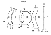
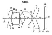
図1は、本発明の一実施の形態に係る撮像レンズの構成例を示している。この構成例は、後述の第1の数値実施例(図3,図4)のレンズ構成に対応している。また、図2は、本実施の形態に係る撮像レンズの他の構成例を示している。図2の構成例は、後述の第2の数値実施例(図5,図6)のレンズ構成に対応している。なお、図1,図2において、符号Riは、最も物体側の構成要素の面を1番目として、像側(結像側)に向かうに従い順次増加するようにして符号を付したi番目(i=1〜10)の面の曲率半径を示す。符号Diは、i番目の面とi+1番目の面との光軸Z1上の面間隔を示す。なお、各構成例共に基本的な構成は同じなので、以下では、図1に示した撮像レンズの構成を基本にして説明する。
【0017】
この撮像レンズは、例えば、CCDやCMOSなどの撮像素子を用いた携帯用モジュールカメラやデジタルカメラ等に搭載されて使用されるものである。この撮像レンズは、光軸Z1に沿って、第1レンズG1、第2レンズG2、絞りSt、第3レンズG3、および第4レンズG4が、物体側より順に配設された構成となっている。この撮像レンズの結像面(撮像面)には、図示しないCCDなどの撮像素子が配置される。CCDの撮像面付近には、撮像面を保護するためのカバーガラスCGが配置されている。第4レンズG4と結像面(撮像面)との間には、カバーガラスCGのほか、赤外線カットフィルタやローパスフィルタなどの他の光学部材が配置されていても良い。
【0018】
第1レンズG1は、物体側に凸面を向けたメニスカス形状となっている。第1レンズG1は、例えば負のパワーを有している。第1レンズG1は、球面レンズまたは非球面レンズとなっている。非球面レンズにする場合、第1レンズG1の物体側の面を非球面形状にすると良い。第2レンズG2は、物体側の面が凸面形状で正のパワーを有している。第2レンズG2の像側の面は、例えば凸面形状となっている。
【0019】
第3レンズG3は、少なくとも1面が非球面形状であり、かつ物体側の面を凹面形状とした正または負のパワーを有するメニスカス形状となっている。
【0020】
第4レンズG4は、両面が非球面形状で、かつ近軸近傍における形状が物体側に凸面を向けたメニスカス形状となっている。第4レンズG4は、有効径の範囲内で、物体側の面が、周辺に行くほど正のパワーが弱くなる非球面形状であり、像側の面が、周辺に行くほど負のパワーが弱くなる非球面形状であることが望ましい。これにより、第4レンズG4は、例えば、物体側の面が、近軸近傍では凸面形状で、周辺部では凹面形状となり、像側の面が、近軸近傍では凹面形状で、周辺部では凸面形状となっている。
【0021】
なお、本実施の形態において、近軸近傍におけるレンズ形状は、例えば後述の非球面式(A)において、係数Kに係る部分(係数Aiに係る多項式部分を除いた部分)によって表される。
【0022】
この撮像レンズは、以下の条件式(1)を満足するように構成されている。ただし、式(1)において、fは、全体の焦点距離を示し、fAは、第1レンズG1および第2レンズG2の合成焦点距離を示している。
0.8<fA/f<2.0 ……(1)
【0023】
この撮像レンズにおいて、絞りStよりも前群の第1レンズG1および第2レンズG2は、主に加工性および製造コストの点を考慮して、例えばガラス材料で構成されていることが望ましい。特に第2レンズG2を、研磨加工可能なガラスの球面レンズとすることで、ローコスト化を図ることができる。第1レンズG1を非球面形状にする場合には、ガラスモールドレンズにすることが望ましい。一方、絞りStよりも後群の第3レンズG3および第4レンズG4は、特殊な非球面形状加工を行うため、光学樹脂材料(プラスチックレンズ)で構成されていることが望ましい。
【0024】
次に、以上のように構成された撮像レンズの作用および効果を説明する。
【0025】
この撮像レンズでは、第1レンズG1をメニスカスレンズ、第2レンズG2を正レンズ、第3および第4レンズG3,G4を非球面レンズとした4枚構成とし、さらに絞りStを第2レンズG2と第3レンズG3との間に配することで、4枚という少ないレンズ構成ながら、高い性能とコンパクトなレンズ系を実現している。
【0026】
この撮像レンズでは、第3および第4レンズG3,G4を非球面レンズとしていることで、大きな収差補正効果が得られる。特に、第4レンズG4を、有効径の範囲内で、物体側の面が、周辺に行くほど正のパワーが弱くなる非球面形状、像側の面が、周辺に行くほど負のパワーが弱くなる非球面形状とすることで、像面湾曲の補正を始めとして、収差補正に関してより大きな効果が得られる。
【0027】
条件式(1)は、絞りStよりも物体側の前群(第1および第2レンズG1,G2)の合成焦点距離に関するものである。条件式(1)の数値範囲を上回ると、前群のパワーが小さくなり過ぎて全長を短くするのが困難となる。ところで一般に、デジタルカメラ等においては、CCD等の撮像素子の特性上、光線が撮像面に垂直に近い状態で入射することが望ましい。従って、デジタルカメラ等に搭載される撮像レンズでは、テレセントリック性が確保されていることが望ましい。条件式(1)の数値範囲を下回ると、射出光線角度が大きくなり、テレセントリック性が悪化するため好ましくない。
【0028】
また、各レンズの材料およびその加工法を、上記したようにそのレンズ形状に合わせた最適なものとすることで、ローコスト化を図ることができる。
【0029】
このように、本実施の形態に係る撮像レンズによれば、4枚という少ないレンズ枚数で非球面を有効に用いることにより、携帯用モジュールカメラにも搭載可能なコンパクト性を満足しつつ、性能面ではデジタルカメラへの搭載をも視野に入れた、ローコストで高性能な撮像レンズが実現できる。
【0030】
【実施例】
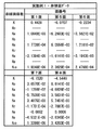
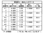
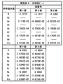
次に、本実施の形態に係る撮像レンズの具体的な数値実施例について説明する。以下では、第1および第2の数値実施例(実施例1,2)をまとめて説明する。図3,図4は、図1に示した撮像レンズの構成に対応する具体的なレンズデータ(実施例1)を示している。また、図5,図6は、図2に示した撮像レンズの構成に対応する具体的なレンズデータ(実施例2)を示している。図3および図5には、その実施例のレンズデータのうち基本的なデータ部分を示し、図4および図6には、その実施例のレンズデータのうち非球面形状に関するデータ部分を示す。
【0031】
各図に示したレンズデータにおける面番号Siの欄には、各実施例の撮像レンズについて、最も物体側の構成要素の面を1番目として、像側に向かうに従い順次増加するようにして符号を付したi番目(i=1〜10)の面の番号を示している。曲率半径Riの欄には、図1,図2で付した符号Riに対応させて、物体側からi番目の面の曲率半径の値を示す。面間隔Diの欄についても、図1,図2で付した符号に対応させて、物体側からi番目の面Siとi+1番目の面Si+1との光軸上の間隔を示す。曲率半径Riおよび面間隔Diの値の単位はミリメートル(mm)である。Ndj,νdjの欄には、それぞれ、カバーガラスCGも含めて、物体側からj番目(j=1〜5)のレンズ要素のd線(587.6nm)に対する屈折率およびアッベ数の値を示す。なお、カバーガラスCGの両面の曲率半径R9,R10の値が0(ゼロ)となっているが、これは、平面であることを示す。図3および図5にはまた、諸データとして、全系の焦点距離f(mm)、Fナンバー(FNO.)、画角2ω(ω:半画角)の値を同時に示す。
【0032】
図3および図5の各レンズデータにおいて、面番号の左側に付された記号「*」は、そのレンズ面が非球面形状であることを示す。各実施例共に、第1レンズG1の物体側の面S1と、第3レンズG3の両面S5,S6と、第4レンズG4の両面S7,S8とが非球面形状となっている。基本レンズデータには、これらの非球面の曲率半径として、光軸近傍(近軸近傍)の曲率半径の数値を示している。
【0033】
図4および図6の各非球面データの数値において、記号“E”は、その次に続く数値が10を底とした“べき指数”であることを示し、その10を底とした指数関数で表される数値が“E”の前の数値に乗算されることを示す。例えば、「1.0E−02」であれば、「1.0×10⁻²」であることを示す。
【0034】
各非球面データには、以下の式(A)によって表される非球面形状の式における各係数Ai,Kの値を記す。Zは、より詳しくは、光軸から高さhの位置にある非球面上の点から、非球面の頂点の接平面(光軸に垂直な平面)に下ろした垂線の長さ(mm)を示す。
【0035】
Z=C・h2/{1+(1−K・C2・h2)1/2}+A3・h3+A4・h4+A5・h5+A6・h6+A7・h7+A8・h8+A9・h9+A10・h10 ……(A)
ただし、
Z:非球面の深さ(mm)
h:光軸からレンズ面までの距離(高さ)(mm)
K:離心率
C:近軸曲率=1/R
(R:近軸曲率半径)
Ai:第i次(i=3〜10)の非球面係数
【0036】
各実施例共に、第1レンズG1の物体側の面S1と、第3レンズG3の両面S5,S6の非球面形状は、非球面係数として、偶数次の係数A4,A6,A8,A10のみを有効に用いて表されている。第4レンズG4の両面S7,S8の非球面形状は、さらに奇数次の非球面係数A3,A7,A9をも有効に用いている。
【0037】
図7は、上述の条件式(1)に対応する値を、各実施例についてまとめて示したものである。図7に示したように、各実施例の値が、条件式(1)の数値範囲内となっている。
【0038】
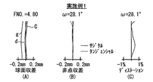
図8(A)〜(C)は、実施例1の撮像レンズにおける球面収差、非点収差、およびディストーション(歪曲収差)を示している。各収差図には、d線を基準波長とした収差を示すが、球面収差図には、g線(波長435.8nm),C線(波長656.3nm)についての収差も示す。非点収差図において、実線はサジタル方向、破線はタンジェンシャル方向の収差を示す。同様に、実施例2についての諸収差を図9(A)〜(C)に示す。
【0039】
以上の各レンズデータおよび各収差図から分かるように、各実施例について、良好に収差補正がなされている。また、全長のコンパクト化が図られている。
【0040】
なお、本発明は、上記実施の形態および各実施例に限定されず種々の変形実施が可能である。例えば、各レンズ成分の曲率半径、面間隔および屈折率の値などは、上記各数値実施例で示した値に限定されず、他の値をとり得る。
【0041】
【発明の効果】
以上説明したように、本発明の撮像レンズによれば、第1レンズをメニスカスレンズ、第2レンズを正レンズ、第3および第4レンズを非球面レンズとした4枚構成とし、さらに絞りを第2レンズと第3レンズとの間に配し、かつ、絞りよりも物体側の前群の合成焦点距離に関して所定の条件式(1)を満足するようにしたので、少ないレンズ枚数でローコスト化を図りながら、非球面を有効に用いることにより、高性能、かつコンパクトな構成を実現できる。
【0042】
特に、本発明の撮像レンズにおいて、第2レンズのレンズ材をガラス材料にした場合には、第2レンズを、例えば研磨加工可能なガラスの球面レンズとすることにより、よりローコスト化を図ることができる。また、第4レンズを、有効径の範囲内で、物体側の面が、周辺に行くほど正のパワーが弱くなる非球面形状とし、像側の面が、周辺に行くほど負のパワーが弱くなる非球面形状とした場合には、像面湾曲などの補正がし易くなり、より高性能化を図ることができる。
【図面の簡単な説明】
【図1】本発明の一実施の形態に係る撮像レンズの構成例を示すものであり、実施例1に対応するレンズ断面図である。
【図2】本発明の一実施の形態に係る撮像レンズの他の構成例を示すものであり、実施例2に対応するレンズ断面図である。
【図3】実施例1に係る撮像レンズの基本レンズデータを示す図である。
【図4】実施例1に係る撮像レンズの非球面に関するデータを示す図である。
【図5】実施例2に係る撮像レンズの基本レンズデータを示す図である。
【図6】実施例2に係る撮像レンズの非球面に関するデータを示す図である。
【図7】各実施例に係る撮像レンズが満たす条件式の値を示す図である。
【図8】実施例1に係る撮像レンズの球面収差、非点収差、およびディストーションを示す収差図である。
【図9】実施例2に係る撮像レンズの球面収差、非点収差、およびディストーションを示す収差図である。
【符号の説明】
CG…カバーガラス、Gj…物体側から第j番目のレンズ、Ri…物体側から第i番目のレンズ面の曲率半径、Di…物体側から第i番目と第i+1番目のレンズ面との面間隔、Z1…光軸。[0001]
BACKGROUND OF THE INVENTION
The present invention relates to an imaging lens particularly suitable for mounting on a small imaging device.
[0002]
[Prior art]
In recent years, with the spread of personal computers to ordinary homes and the like, digital still cameras (hereinafter simply referred to as digital cameras) capable of inputting image information such as photographed landscapes and human images to personal computers have rapidly spread. It's getting on. In addition, with the advancement of functions of mobile phones, module cameras for image input (mobile module cameras) are often mounted on mobile phones.
[0003]
In these image pickup apparatuses, an image pickup element such as a charge coupled device (CCD) or a complementary metal oxide semiconductor (CMOS) is used. In recent years, such an imaging apparatus has been miniaturized as the entire apparatus because the imaging element has been miniaturized. In addition, the number of pixels of the image sensor has been increased, and higher resolution and higher performance have been achieved.
[0004]
As an imaging lens used for such an imaging device, for example, there are those described in the following patent documents.
[0005]
[Patent Document 1]
Japanese Patent Laid-Open No. 10-48516 [Patent Document 2]
JP 2002-221659 A [Patent Document 3]
US Pat. No. 6,441,971 [Patent Document 4]
JP-T-2002-517773 Publication [0006]
[Problems to be solved by the invention]
As described above, recent image pickup devices have been reduced in size and increased in pixels, and accordingly, an image pickup lens for a digital camera, in particular, is required to have high resolution performance and a compact configuration. On the other hand, the imaging lens of a portable module camera has conventionally been mainly required for cost and compactness. However, recently, the imaging module of a portable module camera is also increasing in number of pixels, and the performance is reduced. The demand is getting higher.
[0007]
Therefore, it is desired to develop a wide variety of lenses that comprehensively consider cost, performance, and compactness. For example, there is a demand for the development of a low-cost and high-performance imaging lens that satisfies the compactness that can be mounted on a portable module camera and has a performance in view of mounting on a digital camera.
[0008]
In order to meet such demands, for example, it is conceivable that the number of lenses is three or four in order to achieve compactness and low cost, and an aspherical surface is actively used in order to achieve high performance. . In this case, the aspherical surface contributes to compactness and high performance, but it is disadvantageous in terms of manufacturability and tends to be costly. Therefore, it is desirable to fully consider manufacturability. The lenses described in each of the above patent documents have a configuration using three or four aspheric surfaces, but the above-described overall performance is insufficient. Or is lacking. In general, a three-lens configuration is sufficient for a portable module camera in terms of performance, but tends to be insufficient in terms of performance for a digital camera. In addition, the four-lens configuration can improve the performance as compared with the three-lens configuration, but tends to be disadvantageous in terms of cost and compactness.
[0009]
The present invention has been made in view of such problems, and an object thereof is to provide an imaging lens capable of realizing a high-performance and compact configuration by effectively using an aspherical surface while effectively reducing the cost with a small number of lenses. It is to provide.
[0010]
[Means for Solving the Problems]
An imaging lens according to the present invention includes, in order from the object side, a first meniscus lens having a convex surface facing the object side, a second lens having a convex surface on the object side and having positive power, and an aperture. A third meniscus lens having positive or negative power with an aspherical surface and a concave surface on the object side, and both surfaces are aspherical and the shape near the paraxial is convex on the object side And a fourth lens having a meniscus shape facing the surface, and is configured to satisfy the following conditional expression (1).
[0011]
0.8 <fA / f <2.0 (1)
Here, f represents the overall focal length, and fA represents the combined focal length of the first lens and the second lens.
[0012]
In the imaging lens according to the present invention, as described above, the first lens is a meniscus lens, the second lens is a positive lens, the third and fourth lenses are aspherical lenses, and the diaphragm is the second lens and the second lens. By arranging between three lenses, the minimum optical performance that can be applied to not only a portable module camera but also a digital camera can be obtained with a small lens configuration of four lenses. In particular, the third and fourth aspherical lenses greatly contribute to aberration correction. Further, by satisfying the expression (1) with respect to the combined focal length of the front group (first and second lenses) on the object side of the stop, the emission ray angle (telecentricity) suitable for an image sensor such as a CCD is satisfied. However, the overall length can be reduced. Accordingly, high performance and compactness can be achieved by effectively using the aspherical surface while reducing the cost with a small number of lenses.
[0013]
In this imaging lens, the lens material of the second lens is preferably a glass material. In particular, the second lens is a spherical glass lens that can be polished, which contributes mainly to cost reduction.
[0014]
In addition, the fourth lens has an aspherical shape in which the positive power decreases as the object side surface goes to the periphery within the effective diameter range, and the negative power decreases as the image side surface goes to the periphery. A weak aspheric shape is desirable. By using such a special aspherical shape, it becomes easy to correct curvature of field and the like, which mainly contributes to high performance.
[0015]
DETAILED DESCRIPTION OF THE INVENTION
Hereinafter, embodiments of the present invention will be described in detail with reference to the drawings.
[0016]
FIG. 1 shows a configuration example of an imaging lens according to an embodiment of the present invention. This configuration example corresponds to the lens configuration of a first numerical example (FIGS. 3 and 4) described later. FIG. 2 shows another configuration example of the imaging lens according to the present embodiment. The configuration example of FIG. 2 corresponds to the lens configuration of a second numerical example (FIGS. 5 and 6) described later. In FIG. 1 and FIG. 2, the symbol Ri is the i-th (i) (i) (i) where the surface of the most object-side component is the first and increases sequentially toward the image side (imaging side). = 1 to 10) indicates the radius of curvature of the surface. The symbol Di indicates the surface interval on the optical axis Z1 between the i-th surface and the i + 1-th surface. Since the basic configuration is the same in each configuration example, the following description is based on the configuration of the imaging lens shown in FIG.
[0017]
This imaging lens is used by being mounted on, for example, a portable module camera or a digital camera using an imaging element such as a CCD or CMOS. This imaging lens has a configuration in which a first lens G1, a second lens G2, a diaphragm St, a third lens G3, and a fourth lens G4 are arranged in this order from the object side along the optical axis Z1. . An imaging element such as a CCD (not shown) is disposed on the imaging surface (imaging surface) of the imaging lens. A cover glass CG for protecting the imaging surface is disposed near the imaging surface of the CCD. In addition to the cover glass CG, other optical members such as an infrared cut filter and a low-pass filter may be disposed between the fourth lens G4 and the imaging surface (imaging surface).
[0018]
The first lens G1 has a meniscus shape with a convex surface facing the object side. The first lens G1 has, for example, negative power. The first lens G1 is a spherical lens or an aspheric lens. In the case of using an aspheric lens, the object side surface of the first lens G1 may be aspheric. The second lens G2 has a positive power with a convex surface on the object side. The image side surface of the second lens G2 has, for example, a convex shape.
[0019]
The third lens G3 has a meniscus shape having positive or negative power in which at least one surface is aspherical and the object side surface is concave.
[0020]
The fourth lens G4 has a meniscus shape in which both surfaces are aspherical and the shape near the paraxial surface has a convex surface facing the object side. The fourth lens G4 has an aspherical shape in which the object-side surface becomes weaker as the distance toward the periphery falls within the effective diameter range, and the negative power becomes weaker as the image-side surface moves toward the periphery. It is desirable that the aspherical shape is as follows. Thereby, for example, the fourth lens G4 has, for example, a convex surface near the paraxial surface and a concave surface at the periphery, and a concave surface near the paraxial surface, and a convex surface at the periphery near the image side. It has a shape.
[0021]
In the present embodiment, the lens shape in the vicinity of the paraxial axis is represented by, for example, a part relating to the coefficient K (a part excluding the polynomial part relating to the coefficient A i ) in an aspherical expression (A) described later.
[0022]
This imaging lens is configured to satisfy the following conditional expression (1). In Equation (1), f represents the overall focal length, and fA represents the combined focal length of the first lens G1 and the second lens G2.
0.8 <fA / f <2.0 (1)
[0023]
In this imaging lens, it is desirable that the first lens G1 and the second lens G2 in the front group prior to the stop St are made of, for example, a glass material mainly considering the workability and the manufacturing cost. In particular, the cost can be reduced by using a glass spherical lens that can be polished for the second lens G2. When the first lens G1 is aspherical, it is preferably a glass mold lens. On the other hand, it is desirable that the third lens G3 and the fourth lens G4 in the rear group from the stop St are made of an optical resin material (plastic lens) in order to perform special aspherical shape processing.
[0024]
Next, operations and effects of the imaging lens configured as described above will be described.
[0025]
This imaging lens has a four-lens configuration in which the first lens G1 is a meniscus lens, the second lens G2 is a positive lens, the third and fourth lenses G3 and G4 are aspherical lenses, and the stop St is the second lens G2. By arranging it between the third lens G3, high performance and a compact lens system are realized with a small lens configuration of four lenses.
[0026]
In this imaging lens, since the third and fourth lenses G3 and G4 are aspherical lenses, a large aberration correction effect can be obtained. In particular, the fourth lens G4 has an aspherical shape in which the positive power decreases as the object side surface moves closer to the periphery within the effective diameter range, and the negative power decreases as the image side surface moves closer to the periphery. By using the aspherical shape, a greater effect can be obtained with respect to aberration correction, including correction of field curvature.
[0027]
Conditional expression (1) relates to the combined focal length of the front group (first and second lenses G1, G2) closer to the object side than the stop St. If the numerical range of the conditional expression (1) is exceeded, the power of the front group becomes too small and it becomes difficult to shorten the total length. By the way, in general, in a digital camera or the like, it is desirable that a light beam is incident in a state of being nearly perpendicular to the imaging surface because of characteristics of an imaging element such as a CCD. Therefore, it is desirable to ensure telecentricity in an imaging lens mounted on a digital camera or the like. Below the numerical range of the conditional expression (1), the exit ray angle becomes large, and the telecentricity deteriorates, which is not preferable.
[0028]
Further, the cost of each lens can be reduced by optimizing the material and processing method of each lens according to the lens shape as described above.
[0029]
As described above, according to the imaging lens according to the present embodiment, the aspherical surface is effectively used with a small number of lenses of four, thereby satisfying the compactness that can be mounted on a portable module camera and the performance aspect. Therefore, it is possible to realize a low-cost and high-performance imaging lens with a view to mounting on a digital camera.
[0030]
【Example】
Next, specific numerical examples of the imaging lens according to the present embodiment will be described. Hereinafter, the first and second numerical examples (Examples 1 and 2) will be described together. 3 and 4 show specific lens data (Example 1) corresponding to the configuration of the imaging lens shown in FIG. 5 and 6 show specific lens data (Example 2) corresponding to the configuration of the imaging lens shown in FIG. 3 and 5 show basic data portions of the lens data of the embodiment, and FIGS. 4 and 6 show data portions relating to the aspherical shape of the lens data of the embodiment.
[0031]
In the field of the surface number Si in the lens data shown in each figure, for the imaging lens of each embodiment, the surface of the component closest to the object side is the first, and the code is sequentially increased toward the image side. The number of the attached i-th (i = 1 to 10) surface is shown. The column of the radius of curvature Ri indicates the value of the radius of curvature of the i-th surface from the object side, corresponding to the symbol Ri attached in FIGS. The column of the surface interval Di also indicates the interval on the optical axis between the i-th surface Si and the i + 1-th surface Si + 1 from the object side, corresponding to the reference numerals given in FIGS. The unit of the value of the curvature radius Ri and the surface interval Di is millimeter (mm). In the columns Ndj and νdj, the values of the refractive index and Abbe number for the d-line (587.6 nm) of the jth lens element (j = 1 to 5) from the object side, including the cover glass CG, are shown. . In addition, although the value of curvature radius R9, R10 of both surfaces of cover glass CG is 0 (zero), this shows that it is a plane. 3 and 5 also show values of the focal length f (mm), F number (FNO.), And angle of view 2ω (ω: half angle of view) of the entire system as various data.
[0032]
In each lens data of FIGS. 3 and 5, the symbol “*” attached to the left side of the surface number indicates that the lens surface has an aspherical shape. In each embodiment, the object-side surface S1 of the first lens G1, the both surfaces S5 and S6 of the third lens G3, and the both surfaces S7 and S8 of the fourth lens G4 are aspherical. In the basic lens data, the numerical value of the radius of curvature near the optical axis (near the paraxial axis) is shown as the radius of curvature of these aspheric surfaces.
[0033]
4 and 6, the symbol “E” indicates that the next numerical value is a “power exponent” with 10 as the base, and is an exponential function with 10 as the base. Indicates that the numerical value represented is multiplied by the numerical value before “E”. For example, “1.0E-02” indicates “1.0 × 10 −2 ”.
[0034]
In each aspheric surface data, the values of the coefficients A i and K in the aspheric surface expression represented by the following expression (A) are described. More specifically, Z is the length (mm) of a perpendicular line drawn from a point on the aspheric surface at a height h from the optical axis to the tangential plane (plane perpendicular to the optical axis) of the apex of the aspheric surface. Show.
[0035]
Z = C · h 2 / {1+ (1−K · C 2 · h 2 ) 1/2 } + A 3 · h 3 + A 4 · h 4 + A 5 · h 5 + A 6 · h 6 + A 7 · h 7 + A 8・ h 8 + A 9・ h 9 + A 10・ h 10 …… (A)
However,
Z: Depth of aspheric surface (mm)
h: Distance from the optical axis to the lens surface (height) (mm)
K: eccentricity C: paraxial curvature = 1 / R
(R: paraxial radius of curvature)
A i : i-th (i = 3 to 10) aspheric coefficient
In each embodiment, the aspherical shapes of the object-side surface S1 of the first lens G1 and the surfaces S5 and S6 of the third lens G3 are even-order coefficients A 4 , A 6 , A 8 , Only A 10 is used effectively. The aspheric shape of both surfaces S7 and S8 of the fourth lens G4 further effectively uses odd-order aspheric coefficients A 3 , A 7 and A 9 .
[0037]
FIG. 7 collectively shows values corresponding to the above-described conditional expression (1) for the respective examples. As shown in FIG. 7, the values of the respective examples are within the numerical range of the conditional expression (1).
[0038]
8A to 8C show spherical aberration, astigmatism, and distortion (distortion aberration) in the imaging lens of Example 1. FIG. Each aberration diagram shows aberrations with the d-line as a reference wavelength, while the spherical aberration diagram also shows aberrations for the g-line (wavelength 435.8 nm) and C-line (wavelength 656.3 nm). In the astigmatism diagram, the solid line indicates the sagittal direction and the broken line indicates the tangential direction. Similarly, various aberrations for Example 2 are shown in FIGS.
[0039]
As can be seen from the lens data and aberration diagrams described above, the aberration correction is satisfactorily performed for each example. Also, the overall length is made compact.
[0040]
In addition, this invention is not limited to the said embodiment and each Example, A various deformation | transformation implementation is possible. For example, the radius of curvature, the surface interval, and the refractive index of each lens component are not limited to the values shown in the above numerical examples, and may take other values.
[0041]
【The invention's effect】
As described above, according to the imaging lens of the present invention, the first lens has a meniscus lens, the second lens has a positive lens, the third and fourth lenses have aspherical lenses, and the aperture is further reduced. Since it is arranged between the second lens and the third lens and satisfies the predetermined conditional expression (1) with respect to the combined focal length of the front group closer to the object side than the stop, the cost can be reduced with a small number of lenses. While effectively using an aspherical surface, a high-performance and compact configuration can be realized.
[0042]
In particular, in the imaging lens of the present invention, when the lens material of the second lens is made of a glass material, the cost can be further reduced by using, for example, a glass spherical lens that can be polished. it can. In addition, the fourth lens has an aspherical shape in which the positive power decreases as the object side surface goes to the periphery within the effective diameter range, and the negative power decreases as the image side surface goes to the periphery. In the case of the aspherical shape, it becomes easy to correct field curvature and the like, and higher performance can be achieved.
[Brief description of the drawings]
FIG. 1 illustrates a configuration example of an imaging lens according to an embodiment of the present invention, and is a lens cross-sectional view corresponding to Example 1. FIG.
FIG. 2 is a lens cross-sectional view illustrating another configuration example of an imaging lens according to an embodiment of the present invention and corresponding to Example 2;
3 is a diagram illustrating basic lens data of the imaging lens according to Example 1. FIG.
4 is a diagram illustrating data relating to an aspheric surface of the imaging lens according to Example 1. FIG.
5 is a diagram illustrating basic lens data of an imaging lens according to Example 2. FIG.
6 is a diagram illustrating data relating to an aspheric surface of the imaging lens according to Example 2. FIG.
FIG. 7 is a diagram illustrating the values of conditional expressions satisfied by the imaging lens according to each embodiment.
FIG. 8 is an aberration diagram showing spherical aberration, astigmatism, and distortion of the imaging lens according to Example 1;
FIG. 9 is an aberration diagram showing spherical aberration, astigmatism, and distortion of the imaging lens according to Example 2.
[Explanation of symbols]
CG ... cover glass, Gj ... j-th lens from the object side, Ri ... radius of curvature of the i-th lens surface from the object side, Di ... surface distance between the i-th and i + 1-th lens surfaces from the object side , Z1... Optical axis.
Claims (2)
物体側に凸面を向けたメニスカス形状の第1レンズと、
物体側の面が凸面形状で正のパワーを有する第2レンズと、
絞りと、
少なくとも1面を非球面形状とし、かつ物体側の面を凹面形状とした正または負のパワーを有するメニスカス形状の第3レンズと、
両面が非球面形状で、かつ近軸近傍における形状が物体側に凸面を向けたメニスカス形状である第4レンズと
を備え、
かつ、以下の条件式(1)を満足するように構成されている
ことを特徴とする撮像レンズ。
0.8<fA/f<2.0 ……(1)
ただし、
f:全体の焦点距離
fA:第1レンズおよび第2レンズの合成焦点距離From the object side,
A first meniscus lens with a convex surface facing the object side;
A second lens having a positive power with a convex surface on the object side;
Aperture,
A meniscus third lens having a positive or negative power, wherein at least one surface is aspherical and the object side surface is concave;
A fourth lens having a meniscus shape in which both surfaces are aspherical and the shape near the paraxial surface is convex toward the object side;
The imaging lens is configured to satisfy the following conditional expression (1).
0.8 <fA / f <2.0 (1)
However,
f: Overall focal length fA: Composite focal length of the first lens and the second lens
前記第4レンズは、有効径の範囲内で、物体側の面が、周辺に行くほど正のパワーが弱くなる非球面形状であり、像側の面が、周辺に行くほど負のパワーが弱くなる非球面形状である
ことを特徴とする請求項1記載の撮像レンズ。The second lens is made of a glass material,
The fourth lens has an aspherical shape in which the positive power is weakened toward the periphery of the object side surface within the effective diameter range, and the negative power is weakened as the surface of the image side is peripheral. The imaging lens according to claim 1, wherein the imaging lens has an aspheric shape.
Priority Applications (1)
| Application Number | Priority Date | Filing Date | Title |
|---|---|---|---|
| JP2003094150A JP4138552B2 (en) | 2003-03-31 | 2003-03-31 | Imaging lens |
Applications Claiming Priority (1)
| Application Number | Priority Date | Filing Date | Title |
|---|---|---|---|
| JP2003094150A JP4138552B2 (en) | 2003-03-31 | 2003-03-31 | Imaging lens |
Publications (2)
| Publication Number | Publication Date |
|---|---|
| JP2004302057A JP2004302057A (en) | 2004-10-28 |
| JP4138552B2 true JP4138552B2 (en) | 2008-08-27 |
Family
ID=33406778
Family Applications (1)
| Application Number | Title | Priority Date | Filing Date |
|---|---|---|---|
| JP2003094150A Expired - Fee Related JP4138552B2 (en) | 2003-03-31 | 2003-03-31 | Imaging lens |
Country Status (1)
| Country | Link |
|---|---|
| JP (1) | JP4138552B2 (en) |
Cited By (1)
| Publication number | Priority date | Publication date | Assignee | Title |
|---|---|---|---|---|
| US9465196B2 (en) | 2013-12-30 | 2016-10-11 | Genius Electronic Optical Co., Ltd. | Optical imaging lens and electronic device comprising the same |
Families Citing this family (18)
| Publication number | Priority date | Publication date | Assignee | Title |
|---|---|---|---|---|
| JP4980590B2 (en) | 2005-07-04 | 2012-07-18 | 富士フイルム株式会社 | Imaging lens |
| JP4828317B2 (en) | 2005-09-29 | 2011-11-30 | 富士フイルム株式会社 | Imaging lens |
| JP4963187B2 (en) * | 2006-04-05 | 2012-06-27 | 富士フイルム株式会社 | Imaging lens and imaging apparatus |
| ATE408852T1 (en) | 2006-06-15 | 2008-10-15 | Fujinon Corp | COMPACT LENS WITH FOUR INDIVIDUAL LENSES |
| JP4932510B2 (en) | 2007-01-30 | 2012-05-16 | 富士フイルム株式会社 | Imaging lens |
| JP5096057B2 (en) | 2007-07-10 | 2012-12-12 | 富士フイルム株式会社 | Imaging lens, camera module, and imaging device |
| JP5475978B2 (en) | 2008-10-24 | 2014-04-16 | 富士フイルム株式会社 | Imaging lens, camera module, and imaging device |
| JP5322582B2 (en) * | 2008-10-30 | 2013-10-23 | 三洋電機株式会社 | Lens device, photographing device |
| KR101358646B1 (en) * | 2012-06-29 | 2014-02-12 | 주식회사 나무가 | Fast Lens for near infrared ray and camera using the lens |
| CN103135206B (en) | 2012-09-07 | 2016-04-20 | 玉晶光电(厦门)有限公司 | Portable electron device and its optical imaging lens |
| TWI472793B (en) | 2012-09-14 | 2015-02-11 | Largan Precision Co Ltd | Photographing optical lens system |
| TWI443371B (en) | 2012-09-26 | 2014-07-01 | Largan Precision Co Ltd | Image capturing lens assembly |
| CN106199923B (en) * | 2016-08-31 | 2018-10-09 | 中山联合光电科技股份有限公司 | Wide Angle Optical System |
| CN110320637B (en) * | 2018-03-30 | 2023-05-30 | 光芒光学股份有限公司 | Lens and method for manufacturing the same |
| CN109633870B (en) * | 2019-02-25 | 2021-09-03 | 宁波舜宇车载光学技术有限公司 | Optical lens and imaging apparatus |
| CN110908076B (en) * | 2019-12-10 | 2021-09-24 | 诚瑞光学(常州)股份有限公司 | Camera optics |
| CN111025544B (en) * | 2019-12-23 | 2021-10-22 | 诚瑞光学(常州)股份有限公司 | Camera optics |
| CN111929828B (en) * | 2020-09-03 | 2022-03-01 | 诚瑞光学(苏州)有限公司 | Camera optics |
-
2003
- 2003-03-31 JP JP2003094150A patent/JP4138552B2/en not_active Expired - Fee Related
Cited By (1)
| Publication number | Priority date | Publication date | Assignee | Title |
|---|---|---|---|---|
| US9465196B2 (en) | 2013-12-30 | 2016-10-11 | Genius Electronic Optical Co., Ltd. | Optical imaging lens and electronic device comprising the same |
Also Published As
| Publication number | Publication date |
|---|---|
| JP2004302057A (en) | 2004-10-28 |
Similar Documents
| Publication | Publication Date | Title |
|---|---|---|
| JP3717488B2 (en) | Single focus lens | |
| JP4828317B2 (en) | Imaging lens | |
| JP4932510B2 (en) | Imaging lens | |
| JP5037963B2 (en) | Imaging lens | |
| JP4804856B2 (en) | Single focus lens | |
| JP5063434B2 (en) | Imaging lens | |
| US7532415B2 (en) | Imaging lens | |
| JP4949711B2 (en) | Imaging lens | |
| JP4138552B2 (en) | Imaging lens | |
| JP3717489B2 (en) | Single focus lens | |
| JP2008241999A (en) | Imaging lens | |
| JP3768509B2 (en) | Single focus lens and imaging device | |
| JP2011221561A (en) | Imaging lens | |
| JP2005017440A (en) | Imaging lens | |
| JP2009098513A (en) | Four-lens-type small imaging lens, camera module, and imaging apparatus | |
| JP2009098516A (en) | Four-lens-type small imaging lens, camera module, and imaging apparatus | |
| JP5015719B2 (en) | Four-element compact imaging lens, camera module, and imaging device | |
| JP3768510B2 (en) | Wide angle single focus lens and imaging device | |
| JP2005107369A (en) | Telephoto lens | |
| JP4409242B2 (en) | Single focus lens | |
| JP4804857B2 (en) | Single focus lens | |
| JP4074203B2 (en) | Single focus lens | |
| JP4156961B2 (en) | Single focus lens | |
| JP4804858B2 (en) | Single focus lens | |
| JP5301795B2 (en) | Imaging lens |
Legal Events
| Date | Code | Title | Description |
|---|---|---|---|
| A621 | Written request for application examination |
Free format text: JAPANESE INTERMEDIATE CODE: A621 Effective date: 20050322 |
|
| TRDD | Decision of grant or rejection written | ||
| A01 | Written decision to grant a patent or to grant a registration (utility model) |
Free format text: JAPANESE INTERMEDIATE CODE: A01 Effective date: 20080516 |
|
| A01 | Written decision to grant a patent or to grant a registration (utility model) |
Free format text: JAPANESE INTERMEDIATE CODE: A01 |
|
| A61 | First payment of annual fees (during grant procedure) |
Free format text: JAPANESE INTERMEDIATE CODE: A61 Effective date: 20080605 |
|
| R150 | Certificate of patent or registration of utility model |
Ref document number: 4138552 Country of ref document: JP Free format text: JAPANESE INTERMEDIATE CODE: R150 Free format text: JAPANESE INTERMEDIATE CODE: R150 |
|
| FPAY | Renewal fee payment (event date is renewal date of database) |
Free format text: PAYMENT UNTIL: 20110613 Year of fee payment: 3 |
|
| FPAY | Renewal fee payment (event date is renewal date of database) |
Free format text: PAYMENT UNTIL: 20110613 Year of fee payment: 3 |
|
| S111 | Request for change of ownership or part of ownership |
Free format text: JAPANESE INTERMEDIATE CODE: R313113 |
|
| FPAY | Renewal fee payment (event date is renewal date of database) |
Free format text: PAYMENT UNTIL: 20110613 Year of fee payment: 3 |
|
| R350 | Written notification of registration of transfer |
Free format text: JAPANESE INTERMEDIATE CODE: R350 |
|
| FPAY | Renewal fee payment (event date is renewal date of database) |
Free format text: PAYMENT UNTIL: 20110613 Year of fee payment: 3 |
|
| FPAY | Renewal fee payment (event date is renewal date of database) |
Free format text: PAYMENT UNTIL: 20120613 Year of fee payment: 4 |
|
| R250 | Receipt of annual fees |
Free format text: JAPANESE INTERMEDIATE CODE: R250 |
|
| FPAY | Renewal fee payment (event date is renewal date of database) |
Free format text: PAYMENT UNTIL: 20120613 Year of fee payment: 4 |
|
| FPAY | Renewal fee payment (event date is renewal date of database) |
Free format text: PAYMENT UNTIL: 20130613 Year of fee payment: 5 |
|
| R250 | Receipt of annual fees |
Free format text: JAPANESE INTERMEDIATE CODE: R250 |
|
| R250 | Receipt of annual fees |
Free format text: JAPANESE INTERMEDIATE CODE: R250 |
|
| R250 | Receipt of annual fees |
Free format text: JAPANESE INTERMEDIATE CODE: R250 |
|
| R250 | Receipt of annual fees |
Free format text: JAPANESE INTERMEDIATE CODE: R250 |
|
| R250 | Receipt of annual fees |
Free format text: JAPANESE INTERMEDIATE CODE: R250 |
|
| R250 | Receipt of annual fees |
Free format text: JAPANESE INTERMEDIATE CODE: R250 |
|
| R250 | Receipt of annual fees |
Free format text: JAPANESE INTERMEDIATE CODE: R250 |
|
| S111 | Request for change of ownership or part of ownership |
Free format text: JAPANESE INTERMEDIATE CODE: R313113 |
|
| R350 | Written notification of registration of transfer |
Free format text: JAPANESE INTERMEDIATE CODE: R350 |
|
| R250 | Receipt of annual fees |
Free format text: JAPANESE INTERMEDIATE CODE: R250 |
|
| S111 | Request for change of ownership or part of ownership |
Free format text: JAPANESE INTERMEDIATE CODE: R313113 |
|
| R250 | Receipt of annual fees |
Free format text: JAPANESE INTERMEDIATE CODE: R250 |
|
| R371 | Transfer withdrawn |
Free format text: JAPANESE INTERMEDIATE CODE: R371 |
|
| R350 | Written notification of registration of transfer |
Free format text: JAPANESE INTERMEDIATE CODE: R350 |
|
| R250 | Receipt of annual fees |
Free format text: JAPANESE INTERMEDIATE CODE: R250 |
|
| LAPS | Cancellation because of no payment of annual fees |