JP4137819B2 - Machine tool with cooling mechanism - Google Patents
Machine tool with cooling mechanism Download PDFInfo
- Publication number
- JP4137819B2 JP4137819B2 JP2004060288A JP2004060288A JP4137819B2 JP 4137819 B2 JP4137819 B2 JP 4137819B2 JP 2004060288 A JP2004060288 A JP 2004060288A JP 2004060288 A JP2004060288 A JP 2004060288A JP 4137819 B2 JP4137819 B2 JP 4137819B2
- Authority
- JP
- Japan
- Prior art keywords
- spindle
- cooling mechanism
- cooling
- machine tool
- heating element
- Prior art date
- Legal status (The legal status is an assumption and is not a legal conclusion. Google has not performed a legal analysis and makes no representation as to the accuracy of the status listed.)
- Expired - Fee Related
Links
Images


Classifications
-
- B—PERFORMING OPERATIONS; TRANSPORTING
- B23—MACHINE TOOLS; METAL-WORKING NOT OTHERWISE PROVIDED FOR
- B23Q—DETAILS, COMPONENTS, OR ACCESSORIES FOR MACHINE TOOLS, e.g. ARRANGEMENTS FOR COPYING OR CONTROLLING; MACHINE TOOLS IN GENERAL CHARACTERISED BY THE CONSTRUCTION OF PARTICULAR DETAILS OR COMPONENTS; COMBINATIONS OR ASSOCIATIONS OF METAL-WORKING MACHINES, NOT DIRECTED TO A PARTICULAR RESULT
- B23Q11/00—Accessories fitted to machine tools for keeping tools or parts of the machine in good working condition or for cooling work; Safety devices specially combined with or arranged in, or specially adapted for use in connection with, machine tools
- B23Q11/12—Arrangements for cooling or lubricating parts of the machine
- B23Q11/126—Arrangements for cooling or lubricating parts of the machine for cooling only
- B23Q11/127—Arrangements for cooling or lubricating parts of the machine for cooling only for cooling motors or spindles
-
- F—MECHANICAL ENGINEERING; LIGHTING; HEATING; WEAPONS; BLASTING
- F28—HEAT EXCHANGE IN GENERAL
- F28F—DETAILS OF HEAT-EXCHANGE AND HEAT-TRANSFER APPARATUS, OF GENERAL APPLICATION
- F28F13/00—Arrangements for modifying heat-transfer, e.g. increasing, decreasing
- F28F13/06—Arrangements for modifying heat-transfer, e.g. increasing, decreasing by affecting the pattern of flow of the heat-exchange media
- F28F13/08—Arrangements for modifying heat-transfer, e.g. increasing, decreasing by affecting the pattern of flow of the heat-exchange media by varying the cross-section of the flow channels
-
- F—MECHANICAL ENGINEERING; LIGHTING; HEATING; WEAPONS; BLASTING
- F28—HEAT EXCHANGE IN GENERAL
- F28F—DETAILS OF HEAT-EXCHANGE AND HEAT-TRANSFER APPARATUS, OF GENERAL APPLICATION
- F28F3/00—Plate-like or laminated elements; Assemblies of plate-like or laminated elements
- F28F3/12—Elements constructed in the shape of a hollow panel, e.g. with channels
-
- F—MECHANICAL ENGINEERING; LIGHTING; HEATING; WEAPONS; BLASTING
- F28—HEAT EXCHANGE IN GENERAL
- F28D—HEAT-EXCHANGE APPARATUS, NOT PROVIDED FOR IN ANOTHER SUBCLASS, IN WHICH THE HEAT-EXCHANGE MEDIA DO NOT COME INTO DIRECT CONTACT
- F28D21/00—Heat-exchange apparatus not covered by any of the groups F28D1/00 - F28D20/00
- F28D2021/0019—Other heat exchangers for particular applications; Heat exchange systems not otherwise provided for
- F28D2021/0028—Other heat exchangers for particular applications; Heat exchange systems not otherwise provided for for cooling heat generating elements, e.g. for cooling electronic components or electric devices
- F28D2021/0029—Heat sinks
-
- Y—GENERAL TAGGING OF NEW TECHNOLOGICAL DEVELOPMENTS; GENERAL TAGGING OF CROSS-SECTIONAL TECHNOLOGIES SPANNING OVER SEVERAL SECTIONS OF THE IPC; TECHNICAL SUBJECTS COVERED BY FORMER USPC CROSS-REFERENCE ART COLLECTIONS [XRACs] AND DIGESTS
- Y10—TECHNICAL SUBJECTS COVERED BY FORMER USPC
- Y10S—TECHNICAL SUBJECTS COVERED BY FORMER USPC CROSS-REFERENCE ART COLLECTIONS [XRACs] AND DIGESTS
- Y10S82/00—Turning
- Y10S82/90—Lathe thermal regulation
-
- Y—GENERAL TAGGING OF NEW TECHNOLOGICAL DEVELOPMENTS; GENERAL TAGGING OF CROSS-SECTIONAL TECHNOLOGIES SPANNING OVER SEVERAL SECTIONS OF THE IPC; TECHNICAL SUBJECTS COVERED BY FORMER USPC CROSS-REFERENCE ART COLLECTIONS [XRACs] AND DIGESTS
- Y10—TECHNICAL SUBJECTS COVERED BY FORMER USPC
- Y10T—TECHNICAL SUBJECTS COVERED BY FORMER US CLASSIFICATION
- Y10T409/00—Gear cutting, milling, or planing
- Y10T409/30—Milling
- Y10T409/303976—Milling with means to control temperature or lubricate
-
- Y—GENERAL TAGGING OF NEW TECHNOLOGICAL DEVELOPMENTS; GENERAL TAGGING OF CROSS-SECTIONAL TECHNOLOGIES SPANNING OVER SEVERAL SECTIONS OF THE IPC; TECHNICAL SUBJECTS COVERED BY FORMER USPC CROSS-REFERENCE ART COLLECTIONS [XRACs] AND DIGESTS
- Y10—TECHNICAL SUBJECTS COVERED BY FORMER USPC
- Y10T—TECHNICAL SUBJECTS COVERED BY FORMER US CLASSIFICATION
- Y10T409/00—Gear cutting, milling, or planing
- Y10T409/30—Milling
- Y10T409/309352—Cutter spindle or spindle support
-
- Y—GENERAL TAGGING OF NEW TECHNOLOGICAL DEVELOPMENTS; GENERAL TAGGING OF CROSS-SECTIONAL TECHNOLOGIES SPANNING OVER SEVERAL SECTIONS OF THE IPC; TECHNICAL SUBJECTS COVERED BY FORMER USPC CROSS-REFERENCE ART COLLECTIONS [XRACs] AND DIGESTS
- Y10—TECHNICAL SUBJECTS COVERED BY FORMER USPC
- Y10T—TECHNICAL SUBJECTS COVERED BY FORMER US CLASSIFICATION
- Y10T409/00—Gear cutting, milling, or planing
- Y10T409/30—Milling
- Y10T409/309576—Machine frame
-
- Y—GENERAL TAGGING OF NEW TECHNOLOGICAL DEVELOPMENTS; GENERAL TAGGING OF CROSS-SECTIONAL TECHNOLOGIES SPANNING OVER SEVERAL SECTIONS OF THE IPC; TECHNICAL SUBJECTS COVERED BY FORMER USPC CROSS-REFERENCE ART COLLECTIONS [XRACs] AND DIGESTS
- Y10—TECHNICAL SUBJECTS COVERED BY FORMER USPC
- Y10T—TECHNICAL SUBJECTS COVERED BY FORMER US CLASSIFICATION
- Y10T83/00—Cutting
- Y10T83/283—With means to control or modify temperature of apparatus or work
Landscapes
- Engineering & Computer Science (AREA)
- Mechanical Engineering (AREA)
- Physics & Mathematics (AREA)
- Thermal Sciences (AREA)
- General Engineering & Computer Science (AREA)
- Auxiliary Devices For Machine Tools (AREA)
- Turning (AREA)
- Machine Tool Units (AREA)
Description
本発明は、機械の熱変形を抑制するための冷却機構を備えた工作機械に関する。 The present invention relates to a machine tool provided with a cooling mechanism for suppressing thermal deformation of a machine.
主軸頭・コラム等、工作機械を構成する構造物において、主軸モータ等の発熱体から発せられる熱による熱変形は、加工精度低下の原因となる重要な問題である。熱変形の問題の中でも、特に主軸頭や該主軸頭の移動をガイドするコラム等の姿勢変化は、傾きを伴うため、座標軸に並行な方向の変位を補正する熱変位補正プログラムでは補正が不可能である。主軸モータ等の発熱体からの熱によって、主軸頭やコラムが傾けば、主軸の軸線も傾き、主軸に取り付けられた工具も傾くことになり、加工精度を低下させる原因となる。 In a structure constituting a machine tool such as a spindle head and a column, thermal deformation due to heat generated from a heating element such as a spindle motor is an important problem that causes a reduction in machining accuracy. Among the problems of thermal deformation, the change in posture of the spindle head and the column that guides the movement of the spindle head is accompanied by an inclination, so it cannot be corrected by a thermal displacement correction program that corrects displacement in the direction parallel to the coordinate axis It is. If the spindle head or column is tilted by heat from a heating element such as a spindle motor, the axis of the spindle is also tilted, and the tool attached to the spindle is also tilted, causing a reduction in machining accuracy.
この姿勢変化を防止するために、従来、発熱体を直接冷却するか、発熱体から周囲の構造物への熱伝導を抑制する方法が採られている。
例えば、ビルトインモータで主軸を駆動し、該ビルトインモータのステータの外周を約1周する断面積の大きい空気通路を軸方向に間隔をおいて多数本形成し、この各空気通路に断面積が小さい噴出口から圧縮空気を噴射して、圧縮空気の断熱膨張による温度低下により発熱源であるビルトインモータを冷却し、発熱源からの熱が、工作機械の主軸頭やコラム等の他の構造物に伝導することを防止することによって、コラム頭が熱変形することを防止する方法が知られている(特許文献1参照)。
In order to prevent this change in posture, conventionally, a method of directly cooling the heating element or suppressing heat conduction from the heating element to the surrounding structure has been adopted.
For example, a main shaft is driven by a built-in motor, and a large number of air passages having a large cross-sectional area are formed at intervals in the axial direction, and the cross-sectional area is small in each air passage. Compressed air is injected from the jet outlet, and the built-in motor, which is a heat generation source, is cooled by a temperature drop due to adiabatic expansion of the compressed air, and heat from the heat generation source is transferred to other structures such as the spindle head and columns of machine tools. A method for preventing the column head from being thermally deformed by preventing conduction is known (see Patent Document 1).
また、主軸モータをビルトインした主軸頭と、該主軸頭の移動をガイドするコラムとの間の主軸頭基体に、冷却された冷却流体を循環させる冷却流体用通路を設けて、該冷却流体で主軸モータ頭で発生した熱が他の部材に伝導するのを遮断することにより、主軸等の姿勢変化を抑制するようにしたものも知られている(特許文献2参照)。
さらには、主軸モータと主軸が取り付けられたヘッドストックとの間に冷却フランジを取り付けて、該冷却フランジ内に冷却油を循環させて主軸モータで発生した熱が主軸頭に伝導するのを遮断するようにした発明も知られている(特許文献3参照)。
Further, a cooling fluid passage for circulating the cooled cooling fluid is provided in the spindle head base between the spindle head with the built-in spindle motor and the column that guides the movement of the spindle head. It is also known that the change in posture of the main shaft and the like is suppressed by blocking the heat generated in the motor head from being conducted to other members (see Patent Document 2).
Furthermore, a cooling flange is attached between the spindle motor and the head stock to which the spindle is attached, and cooling oil is circulated in the cooling flange to block conduction of heat generated by the spindle motor to the spindle head. Such an invention is also known (see Patent Document 3).
主軸モータ等の発熱体を直接冷却する場合は、特許文献1に示されるように、冷却装置は発熱体を包み込む形状となり、大型になる傾向がある。また発熱体が発する熱と同じ熱量を除去しなければならないため、冷媒が過度に温度上昇するのを防ぐための温度管理装置などの周辺機器が必要となる場合がある。
一方、特許文献2,3に示されるような、発熱体から周囲構造物への熱伝導を、その伝導経路途中に冷却機構を設けて熱伝導を抑制する場合、限られた方向への熱伝導を抑制すればよいため除去する熱量は少ないが、熱伝導の途中に単純に冷媒を流す手法は冷却効果が低い。
そこで、本発明は、効率良く熱伝導を抑制できる冷却機構を備えた工作機械を提供することにある。
When directly cooling a heating element such as a spindle motor, as shown in
On the other hand, as shown in
Then, this invention is providing the machine tool provided with the cooling mechanism which can suppress heat conduction efficiently.
本発明は、冷却機構を備えた工作機械であって、工作機械における発熱体から該発熱体周囲構造物への熱伝導経路の途中に、気体注入口から排気口に向うにしたがい徐々に断面積が増加し、前記排気口で大気圧に開放される冷却通路と、前記気体注入口から大気圧より高圧の気体を注入する気体供給手段とで構成された冷却機構を設け、注入された気体が前記冷却通路を通過する際に断熱膨張して冷却し、前記発熱体から前記構造物への熱伝導を抑制することを特徴とするものである。
前記発熱体は主軸モータであり、前記構造物が主軸頭であり、前記主軸モータと前記主軸頭を、前記冷却機構を備えた部材を介して結合することによって、主軸頭への熱伝導を抑制する。また、主軸頭内に主軸と連結した主軸モータがビルトインされたビルトイン式の工作機械においては、コラムと主軸頭を連結する主軸頭基台における主軸モータ部の部分に前記冷却機構を設け、前記発熱体を構成する主軸モータから前記構造物への熱伝導を該冷却機構で抑制するようにした。
The present invention is a machine tool provided with a cooling mechanism, and in the middle of a heat conduction path from a heating element to a structure around the heating element in the machine tool , the cross-sectional area gradually increases from the gas inlet to the exhaust port. And a cooling mechanism comprising a cooling passage opened to the atmospheric pressure at the exhaust port and a gas supply means for injecting a gas having a pressure higher than the atmospheric pressure from the gas inlet, and the injected gas is When passing through the cooling passage, it is adiabatically expanded and cooled to suppress heat conduction from the heating element to the structure.
The heating element is a spindle motor, the structure is a spindle head, and heat conduction to the spindle head is suppressed by coupling the spindle motor and the spindle head via a member having the cooling mechanism. To do. In a built-in type machine tool in which a spindle motor connected to the spindle is built in the spindle head, the cooling mechanism is provided in the spindle motor portion of the spindle head base connecting the column and the spindle head, and the heat generation Heat conduction from the main shaft motor constituting the body to the structure is suppressed by the cooling mechanism .
冷媒としての気体が断熱膨張することによって冷却されることを利用して、発熱体から他の部材への熱伝導を抑制することから、単に冷媒の気体を流すものと比較し、効率良く熱伝導を抑制することができ、主軸頭やコラム等の工作機械の構造物の姿勢変化を防止し、加工精度を向上させることができる。 Since heat from the heating element to other members is suppressed by utilizing the fact that the refrigerant gas is cooled by adiabatic expansion, it is more efficient to conduct heat more efficiently than a simple refrigerant gas flow. Can be prevented, the posture change of the structure of the machine tool such as the spindle head and the column can be prevented, and the machining accuracy can be improved.
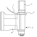
図1は、本発明の第1の実施形態の概要図である。この第1の実施形態は、主軸と別部品として設置されたモータを主軸モータ1とするマシニングセンタの例を示している。主軸頭2における主軸頭基台5が図示しないコラムにガイドされて図1中上下方向に移動するよう構成されている。該主軸頭2には、冷却フランジ3を介して主軸モータ1が取り付けられており、該主軸モータ1の駆動により主軸頭2内の主軸が駆動される構成となっている。
FIG. 1 is a schematic diagram of a first embodiment of the present invention. This 1st Embodiment has shown the example of the machining center which makes the
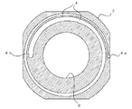
図2は、冷却フランジ3を、図1において紙面垂直方向に切断生じたときの断面図である。この冷却フランジ3は厚みが20〜30mm程度で、内部に冷媒となる空気等の気体が通る冷却通路4が形成しれている。この冷却通路4は、気体注入口4aから気体放出口4bまでの間を、断面積が徐々に増加するように渦巻き状に形成してある。なお、図2において符号6は、主軸モータ1のモータシャフトが通過する穴である。又、気体注入口4aには、図示しないコンプレッサ等の高圧気体供給源より高圧気体を該冷却通路4に導入するための管7が接続されている。
2 is a cross-sectional view of the cooling flange 3 when cut in the direction perpendicular to the paper surface in FIG. The cooling flange 3 has a thickness of about 20 to 30 mm, and a
この工作機械(マシニングセンタ)が稼働するときには、高圧気体供給源より管7を介してより高圧気体(空気等)が冷却通路4に注入される。主軸モータ1が駆動されて該モータ1から発生した熱は、冷却フランジ3を介して主軸頭2に伝導されようとするが、冷却フランジ3に注入された高圧気体は、冷却通路4の断面積が徐々に増加していることから、断熱膨張して温度降下し、冷却フランジ3から熱を吸収し、主軸モータ1で発生した熱の伝導の経路を冷却することになり、主軸頭2への熱伝導を抑制することになる。
When this machine tool (machining center) is operated, a high-pressure gas (air or the like) is injected into the
単に冷却フランジ3に冷媒の高圧気体を通過させることによる冷却と異なり、気体放出口4bに向かうにつれて冷却通路の断面積が徐々増大することにより気体が断熱膨張して冷却されることを利用して、冷却効果を大きくして、より確実に主軸モータ1で発生した熱を主軸頭等の他の構造物に伝導することを防止しているものである。
Unlike the cooling by simply passing the high-pressure gas of the refrigerant through the cooling flange 3, the fact that the gas is adiabatically expanded and cooled by gradually increasing the cross-sectional area of the cooling passage toward the gas discharge port 4b is utilized. The cooling effect is increased to prevent the heat generated by the
図3にビルトインモータ式の工作機械に本発明を適用した第2の実施形態の概要図である。ビルトインモータ式の工作機械は、主軸モータおよび軸受で発生する熱がシャフトや主軸頭、コラム等に伝わり、熱膨張する。シャフトは主に長さ方向に伸びるだけで、傾きを発生させる原因にはなりにくいが、主軸頭やコラムに熱が伝わると、機体が傾く原因となる。 FIG. 3 is a schematic diagram of a second embodiment in which the present invention is applied to a built-in motor type machine tool. In a built-in motor type machine tool, heat generated by a spindle motor and a bearing is transferred to a shaft, a spindle head, a column, etc., and is thermally expanded. The shaft mainly extends in the length direction and is unlikely to cause tilting. However, if heat is transmitted to the spindle head or column, the airframe tilts.
そこで、本題2の実施形態では、図3に示すように、主軸モータと主軸とが一体的に構成された主軸頭10の主軸頭基台11におけるモータ10a寄りの部分に冷却通路12が設けられている。図3はこの主軸頭基台11の部分を中央切断した断面図で示している(図4のA−A断面図)。又、図4は、この主軸頭基台11を図1において紙面垂直でかつ上下方向の面で切断した図である。
Therefore, in the embodiment of the
この図4に示すように、モータ10a寄りの主軸頭基台11に設けられた冷却通路12は、気体注入口12aから気体放出口12bまで、その断面積が徐々に増加するように渦巻き状に形成してある。気体注入口12aには図示しない高圧気体供給源より高圧気体を供給する管13が接続されている。
工作機械が稼働されると、高圧気体供給源より高圧気体が管13を介して気体注入口12aから冷却通路12に注入される。冷却通路12は気体の流れる方向に向かって断面積が徐々に増大するものであるから、気体は断熱膨張して冷やされ、ビルトインモータ(主軸モータ)や軸受け部で発生した熱が主軸頭のコラム側(主軸頭基台)やコラムへの熱伝導を抑制する。
As shown in FIG. 4, the
When the machine tool is operated, high-pressure gas is injected from the high-pressure gas supply source into the
以上のように、本発明の冷却機構は、冷媒の気体が断熱膨張することによる温度降下を利用して熱伝導を抑制するものであり、主軸モータ、ビルトインモータ等の熱発生源と工作機械のその他の構造物との間の部材に、この冷却機構を構成する徐々に断面積が増加する冷却通路を形成し、該冷却通路に冷媒の気体を通過させるだけで、効率良く熱伝導を阻止、抑制するものである。
なお、上述した各実施形態では、熱伝導を抑制する発熱体を主軸モータとしたが、発熱体としては主軸モータに限定されるものではなく、加工精度等に影響を与えるような発熱体(各種モータ等)がある場合には、この発熱体と他の構造物間に本発明の上述した冷却機構を設けてもよいものである。
As described above, the cooling mechanism of the present invention suppresses heat conduction by utilizing the temperature drop caused by adiabatic expansion of the refrigerant gas, and is used for heat generation sources such as spindle motors, built-in motors, and machine tools. Forming a cooling passage that gradually increases the cross-sectional area constituting the cooling mechanism in the member between the other structures, and efficiently passing the refrigerant gas through the cooling passage, effectively preventing heat conduction, It is to suppress.
In each of the above-described embodiments, the heating element that suppresses heat conduction is the spindle motor. However, the heating element is not limited to the spindle motor, and the heating element that affects processing accuracy and the like (various types) When there is a motor or the like, the above-described cooling mechanism of the present invention may be provided between the heating element and another structure.
1 主軸モータ
2 主軸頭
3 冷却フランジ
4,12 冷却通路
4a,12a 気体注入口
4b,12b 気体放出口
5,11 主軸頭基台
6 穴
7 管
10 ビルトインモータ式の主軸頭
10a モータ部分
DESCRIPTION OF
Claims (3)
Priority Applications (5)
| Application Number | Priority Date | Filing Date | Title |
|---|---|---|---|
| JP2004060288A JP4137819B2 (en) | 2004-03-04 | 2004-03-04 | Machine tool with cooling mechanism |
| CN2005100085104A CN1663742A (en) | 2004-03-04 | 2005-02-18 | Machine tool provided with cooling mechanism |
| DE200560001214 DE602005001214T2 (en) | 2004-03-04 | 2005-03-03 | Machine tool with cooling device |
| EP20050251267 EP1570949B1 (en) | 2004-03-04 | 2005-03-03 | Machine tool provided with cooling mechanism |
| US11/070,662 US7114895B2 (en) | 2004-03-04 | 2005-03-03 | Machine tool provided with cooling mechanism |
Applications Claiming Priority (1)
| Application Number | Priority Date | Filing Date | Title |
|---|---|---|---|
| JP2004060288A JP4137819B2 (en) | 2004-03-04 | 2004-03-04 | Machine tool with cooling mechanism |
Publications (2)
| Publication Number | Publication Date |
|---|---|
| JP2005246545A JP2005246545A (en) | 2005-09-15 |
| JP4137819B2 true JP4137819B2 (en) | 2008-08-20 |
Family
ID=34747661
Family Applications (1)
| Application Number | Title | Priority Date | Filing Date |
|---|---|---|---|
| JP2004060288A Expired - Fee Related JP4137819B2 (en) | 2004-03-04 | 2004-03-04 | Machine tool with cooling mechanism |
Country Status (5)
| Country | Link |
|---|---|
| US (1) | US7114895B2 (en) |
| EP (1) | EP1570949B1 (en) |
| JP (1) | JP4137819B2 (en) |
| CN (1) | CN1663742A (en) |
| DE (1) | DE602005001214T2 (en) |
Families Citing this family (16)
| Publication number | Priority date | Publication date | Assignee | Title |
|---|---|---|---|---|
| JP2854731B2 (en) * | 1991-07-15 | 1999-02-03 | 鐘紡株式会社 | A reversing device that aligns randomly supplied noodle balls in one direction |
| CN101332561B (en) * | 2007-06-25 | 2012-11-21 | 鸿富锦精密工业(深圳)有限公司 | Machine tool |
| CN101332574B (en) * | 2007-06-28 | 2012-11-21 | 鸿富锦精密工业(深圳)有限公司 | Machine tool |
| CN101332570A (en) * | 2007-06-28 | 2008-12-31 | 鸿富锦精密工业(深圳)有限公司 | Machine tool |
| CN101332575B (en) * | 2007-06-28 | 2013-01-09 | 鸿富锦精密工业(深圳)有限公司 | Machine tool |
| EP2116327A1 (en) * | 2008-05-08 | 2009-11-11 | Siemens Aktiengesellschaft | Machine tool with heat tube |
| EP2342159B1 (en) * | 2008-09-30 | 2020-12-02 | Forced Physics Llc | Method and apparatus for control of fluid temperature and flow |
| CN101538928A (en) * | 2009-04-17 | 2009-09-23 | 柯干兴 | Multi-purpose wall machine |
| TWI394905B (en) * | 2009-08-28 | 2013-05-01 | Ind Tech Res Inst | Feed drive mechanism and connecting assembly thereof |
| KR101724158B1 (en) * | 2011-01-21 | 2017-04-18 | 두산공작기계 주식회사 | The turret of the machine tool of swiss-turn type having Reduce heating structure |
| CN102729096A (en) * | 2012-07-18 | 2012-10-17 | 上海三一精机有限公司 | Ram thermal insulation structure and machine tool including structure |
| KR101494706B1 (en) | 2013-07-12 | 2015-02-23 | 주식회사 포스코 | Apparatus for controlling temperature of spindle joint |
| DE102016216902A1 (en) * | 2016-09-06 | 2018-03-08 | Deckel Maho Pfronten Gmbh | Machine tool for machining a workpiece and spindle carrier assembly for use on such a machine tool |
| JP6378290B2 (en) * | 2016-11-11 | 2018-08-22 | ファナック株式会社 | Machine Tools |
| CN110727295A (en) * | 2018-07-17 | 2020-01-24 | 高文虎 | Intelligent low-temperature gas cooling safety monitoring temperature-regulating circulating system |
| KR20200041103A (en) * | 2018-10-11 | 2020-04-21 | 현대자동차주식회사 | Shear device and aluminum shear method using the same |
Family Cites Families (9)
| Publication number | Priority date | Publication date | Assignee | Title |
|---|---|---|---|---|
| JPS63179048U (en) * | 1987-05-08 | 1988-11-18 | ||
| JP3233664B2 (en) | 1991-09-13 | 2001-11-26 | 土肥 俊郎 | Method and apparatus for planarization polishing of wafer with device |
| JP2741447B2 (en) * | 1991-11-22 | 1998-04-15 | オークマ株式会社 | Cooling structure of rotating shaft |
| AU658303B2 (en) * | 1992-04-28 | 1995-04-06 | Manuel C. Turchan | Adiabatic dry diamond milling system |
| JP3483602B2 (en) * | 1993-12-01 | 2004-01-06 | 富士重工業株式会社 | Cooling dust collector for machine tools |
| US5799553A (en) * | 1995-02-08 | 1998-09-01 | University Of Connecticut | Apparatus for environmentally safe cooling of cutting tools |
| US7008201B2 (en) * | 2001-10-19 | 2006-03-07 | Imperial Research Llc | Gapless screw rotor device |
| US7013986B2 (en) * | 2003-05-12 | 2006-03-21 | Nitto Kohki Co., Ltd. | Impact tool |
| ES2304558T3 (en) * | 2004-03-01 | 2008-10-16 | Wolfgang Linnenbrink | WORKING PROCEDURE AND DEVICE FOR SMOOTHING TOOTHED WHEELS. |
-
2004
- 2004-03-04 JP JP2004060288A patent/JP4137819B2/en not_active Expired - Fee Related
-
2005
- 2005-02-18 CN CN2005100085104A patent/CN1663742A/en active Pending
- 2005-03-03 DE DE200560001214 patent/DE602005001214T2/en not_active Expired - Fee Related
- 2005-03-03 EP EP20050251267 patent/EP1570949B1/en not_active Ceased
- 2005-03-03 US US11/070,662 patent/US7114895B2/en not_active Expired - Fee Related
Also Published As
| Publication number | Publication date |
|---|---|
| CN1663742A (en) | 2005-09-07 |
| US7114895B2 (en) | 2006-10-03 |
| JP2005246545A (en) | 2005-09-15 |
| DE602005001214D1 (en) | 2007-07-12 |
| DE602005001214T2 (en) | 2008-01-24 |
| EP1570949A1 (en) | 2005-09-07 |
| US20050196246A1 (en) | 2005-09-08 |
| EP1570949B1 (en) | 2007-05-30 |
Similar Documents
| Publication | Publication Date | Title |
|---|---|---|
| JP4137819B2 (en) | Machine tool with cooling mechanism | |
| JP4901186B2 (en) | Turbine cooling system | |
| US20060185345A1 (en) | Cooled transition duct for a gas turbine engine | |
| JP2008164276A (en) | Heat exchanger system having manifold of structure integrated with conduit | |
| JP5103151B2 (en) | Cutting fluid supply device | |
| WO2006101563A3 (en) | Multi-part heat exchanger | |
| JP4572042B2 (en) | Metal casing structure | |
| JP6057443B2 (en) | Brush seal assembly | |
| KR20060087228A (en) | A noise suppresser of a room cooler with a bunch fluid tube | |
| JP2005061405A (en) | Convergent-divergent nozzle for turbo-jet | |
| EP3147451A1 (en) | System for cooling gas turbine | |
| WO2006101562A3 (en) | Heat exchanger arrangement | |
| JP2008113492A (en) | Electric motor and electric compressor | |
| JP2004044639A (en) | Spindle device using dynamic-pressure bearing | |
| US9885506B2 (en) | Expansion valve | |
| US11766747B2 (en) | Surface cooler assembly | |
| US20060119101A1 (en) | Pipe having enlarged and reduced diameters, and ejector using thereof | |
| JP6280149B2 (en) | Machine tool spindle equipment | |
| JP2005238440A (en) | Tool for cutting cutting object | |
| EP2647801A2 (en) | Bearing cooling system for flexible shaft turbomachine | |
| JP2006035337A (en) | Coolant tank | |
| JP2002340213A (en) | Flow control valve | |
| TW201822944A (en) | Cutting cooling assembly of machine tool which does not generate thermal energy during a process of supercharging a coolant | |
| JP2006077703A (en) | Acoustic fluid machine with small temperature gradient | |
| US6966176B2 (en) | System and fabrication method for actively cooling high performance components |
Legal Events
| Date | Code | Title | Description |
|---|---|---|---|
| A977 | Report on retrieval |
Free format text: JAPANESE INTERMEDIATE CODE: A971007 Effective date: 20080118 |
|
| A131 | Notification of reasons for refusal |
Free format text: JAPANESE INTERMEDIATE CODE: A131 Effective date: 20080129 |
|
| A521 | Written amendment |
Free format text: JAPANESE INTERMEDIATE CODE: A523 Effective date: 20080219 |
|
| TRDD | Decision of grant or rejection written | ||
| A01 | Written decision to grant a patent or to grant a registration (utility model) |
Free format text: JAPANESE INTERMEDIATE CODE: A01 Effective date: 20080507 |
|
| A01 | Written decision to grant a patent or to grant a registration (utility model) |
Free format text: JAPANESE INTERMEDIATE CODE: A01 |
|
| A61 | First payment of annual fees (during grant procedure) |
Free format text: JAPANESE INTERMEDIATE CODE: A61 Effective date: 20080604 |
|
| R150 | Certificate of patent or registration of utility model |
Free format text: JAPANESE INTERMEDIATE CODE: R150 |
|
| FPAY | Renewal fee payment (event date is renewal date of database) |
Free format text: PAYMENT UNTIL: 20110613 Year of fee payment: 3 |
|
| LAPS | Cancellation because of no payment of annual fees |