JP4137574B2 - Radiation imaging apparatus and radiation imaging program - Google Patents
Radiation imaging apparatus and radiation imaging program Download PDFInfo
- Publication number
- JP4137574B2 JP4137574B2 JP2002285252A JP2002285252A JP4137574B2 JP 4137574 B2 JP4137574 B2 JP 4137574B2 JP 2002285252 A JP2002285252 A JP 2002285252A JP 2002285252 A JP2002285252 A JP 2002285252A JP 4137574 B2 JP4137574 B2 JP 4137574B2
- Authority
- JP
- Japan
- Prior art keywords
- radiation
- phase
- subject
- transmitted
- laplacian
- Prior art date
- Legal status (The legal status is an assumption and is not a legal conclusion. Google has not performed a legal analysis and makes no representation as to the accuracy of the status listed.)
- Expired - Fee Related
Links
- 230000005855 radiation Effects 0.000 title claims description 140
- 238000003384 imaging method Methods 0.000 title claims description 90
- 238000001514 detection method Methods 0.000 claims description 63
- 238000000034 method Methods 0.000 claims description 26
- 238000010276 construction Methods 0.000 claims description 23
- 238000011084 recovery Methods 0.000 claims 4
- 238000012545 processing Methods 0.000 description 31
- 238000010586 diagram Methods 0.000 description 11
- 238000002834 transmittance Methods 0.000 description 11
- OAICVXFJPJFONN-UHFFFAOYSA-N Phosphorus Chemical compound [P] OAICVXFJPJFONN-UHFFFAOYSA-N 0.000 description 6
- 210000001519 tissue Anatomy 0.000 description 6
- 230000005540 biological transmission Effects 0.000 description 5
- 210000000481 breast Anatomy 0.000 description 5
- 230000005469 synchrotron radiation Effects 0.000 description 4
- 210000000988 bone and bone Anatomy 0.000 description 3
- 238000003745 diagnosis Methods 0.000 description 3
- 230000005284 excitation Effects 0.000 description 3
- 230000001678 irradiating effect Effects 0.000 description 3
- 230000003287 optical effect Effects 0.000 description 3
- 238000011160 research Methods 0.000 description 3
- 239000000126 substance Substances 0.000 description 3
- 238000010521 absorption reaction Methods 0.000 description 2
- 230000002238 attenuated effect Effects 0.000 description 2
- 238000010894 electron beam technology Methods 0.000 description 2
- 238000012986 modification Methods 0.000 description 2
- 230000004048 modification Effects 0.000 description 2
- 239000002245 particle Substances 0.000 description 2
- 230000001133 acceleration Effects 0.000 description 1
- 230000001427 coherent effect Effects 0.000 description 1
- 239000000470 constituent Substances 0.000 description 1
- 239000013078 crystal Substances 0.000 description 1
- 230000007423 decrease Effects 0.000 description 1
- 230000006866 deterioration Effects 0.000 description 1
- 238000011161 development Methods 0.000 description 1
- 238000002050 diffraction method Methods 0.000 description 1
- 230000000694 effects Effects 0.000 description 1
- 238000005516 engineering process Methods 0.000 description 1
- 238000002474 experimental method Methods 0.000 description 1
- 230000010365 information processing Effects 0.000 description 1
- 230000008520 organization Effects 0.000 description 1
- 238000012552 review Methods 0.000 description 1
- 238000002604 ultrasonography Methods 0.000 description 1
Images


Description
【0001】
【発明の属する技術分野】
本発明は、放射線撮像により得られた画像情報に基づいて画像を構成するために用いられる放射線撮像方法及び放射線撮像装置、並びに、放射線撮像プログラムに関する。なお、本願において、放射線とは、X線、α線、β線、γ線に加えて、電子線等の粒子線や電磁波を含む広義の放射線を指すものとする。
【0002】
【従来の技術】
従来より、X線等を用いた撮像方法は様々な分野で利用されており、特に医療分野においては、診断のための最も重要な手段の一つとなっている。最初のX線写真が実現されてから、X線写真法は数々の改良を重ねられ、現在では蛍光スクリーンとX線フィルムを組み合わせた方法が主流となっている。一方、近年においては、X線CTや超音波、MRI等の様々なディジタル化された装置が実用化されており、病院内での診断情報処理システム等の構築が進められようとしている。X線画像についても、撮像システムをディジタル化するための多くの研究がなされている。撮像システムをディジタル化することにより、画質の劣化を招くことなく、大量のデータを長期間保存することが可能であり、医療診断情報システムへの発展にも役立つものである。
【0003】
ところで、このようにして得られる放射線画像は、被写体を透過した放射線等の強度を画像の明度に換算することにより生成されたものである。例えば、骨部を含む領域を撮像する場合に、骨部を透過した放射線は大きく減衰し、骨部以外の部位、即ち、軟部を透過した放射線は僅かに減衰する。この場合には、異なる組織を透過した放射線の強度差が大きいので、高コントラストの放射線画像を得ることができる。
【0004】
一方、例えば、乳房等の軟部領域を撮像する場合に、軟部においては全体的に放射線が透過しやすいので、軟部における組織の違いが透過放射線の強度差として現れ難い。このため、軟部については、低コントラストの放射線画像しか得ることができない。このように、従来の放射線撮像法は、軟部における僅かな組織の違いを可視化する方法としては適当ではない。
【0005】
ここで、被写体を透過した放射線等に含まれている情報としては、強度情報の他に位相情報がある。近年、この位相情報を利用して画像を生成する位相コントラスト法が研究されている。位相コントラスト法は、X線等が被写体を透過することにより生じた位相差を画像の明度に変換する画像構成技術である。
【0006】
位相コントラスト法には、干渉計やゾーンプレートを用いることにより生じた干渉X線に基づいて位相差を求める手法や、回折X線に基づいて位相差を求める手法がある。この内、回折X線に基づいて位相差を求める回折法は、次のような原理に基づいて位相差を求める。例えば、X線は、光と同様に波が進行することにより物質中を伝搬する。その伝搬する速度は、物質が有する屈折率によって異なる。このため、位相の揃ったX線を被写体に向けて照射すると、被写体における組織の違いによりX線の伝わり方に相違が生じる。これにより被写体を透過するX線の波面が歪むので、透過X線に基づいて得られたX線画像に回折縞が生じる。この回折縞のパターンは、X線を結像させるスクリーンと被写体との距離やX線の波長によって異なっている。従って、回折縞パターンの異なる2枚以上のX線画像を解析することにより、スクリーンの各位置において生じたX線の位相差を求めることができる。この位相差を明度に換算することにより、被写体における組織の違いが明確に現れたX線画像を得ることができる。
【0007】
特に、被写体の軟部を透過した後の放射線においては、透過した組織の違いにより、透過放射線において強度差よりも位相差の方が大きくなるので、位相コントラスト法を用いることにより、組織間の微妙な相違を可視化することができる。このような位相コントラスト法を用いるために、放射線撮像における撮像条件や、回折縞パターンから位相を復元する手法が検討されている。
【0008】
下記の非特許文献1には、軟X線撮像を行うことによって得られた画像情報に基づいて位相復元を行い、X線画像を構成することが述べられている。この文献においては、位相復元の基本式であるTIE(transport of intensity equation)が用いられている。ここで、rはベクトルである。
【数1】

次に、位相復元の原理について、図12を用いて説明する。図12に示すように、波長λを有するX線は、図の左側から入射し、物体面101を透過し、物体面101から距離zだけ離れたスクリーン102に入射する。ここで、スクリーン102上の位置(x,y)におけるX線の強度をI(x,y)、位相をφ(x,y)とする。このとき、強度I(x,y)と位相φ(x,y)との間には、次式に示す関係が成り立つ。ここで、強度Iは、波の振幅の2乗である。
【数2】
【0010】
しかしながら、このようなTIEを解くことは困難であるため、TIEは、主に近似して用いられていた。下記の非特許文献2には、硬X線撮像によって得られた画像情報に基づいて位相復元を行い、X線画像を構成することが述べられている。この文献においては、式(1)に示すTIEを次のように近似している。まず、式(1)を展開する。なお、以下において、上記文献におけるベクトルrは(x,y)成分に書き換えられている。
【数3】
式(3)の右辺第2項をゼロに近似すると、次式(4)に示す近似式が得られる。
【数4】
【0012】
また、下記の非特許文献3には、異なる波長を有する3種類のX線を用いてX線撮像を行い、得られた画像情報に基づいて位相復元することが述べられている。この文献においては、X線が被写体を透過した直後のX線の位相及び強度と、被写体から所定の距離だけ離れた位置におけるX線の強度との関係に注目している。X撮像を行う際には、図13に示すような構成が想定されている。即ち、図13に示すように、波長λ0、λ1、λ2をそれぞれ有する3種類のX線は、被写体100を透過し、物体面101から距離Rだけ離れた位置に配置されているスクリーン102に入射する。
【0013】
この場合に、r⊥=(x,y)とすると、波長λ0で被写体100を透過した直後のX線の強度I(r⊥,0,λ0)及び位相φ(r⊥,0,λ0)と、波長λmでスクリーン102において検出された回折X線の強度I(r⊥,R,λm)との間には、次のような関係が成り立つ。ただし、次式(5)において、I(r⊥,0,λ0)=exp{−M(r⊥,0,λ0)}である。
【数5】
式(5)において、∇M・∇φ(r⊥,R,λm)が充分小さいときには、次のように近似することができる。
【数6】
さらに、式(6)より、被写体100を透過した直後のX線の強度及び位相は、次のように表される。
【数7】
式(8)における位相のラプラシアン∇2φ(r⊥,R,λ0)について逆ラプラシアン演算を施すことにより、位相φ(r⊥,R,λ0)を求めることができる。さらに、この位相を画像における明度に換算することにより、被写体を表す可視画像を得ることができる。このように、式(8)を用いることにより、波長を変えて得られた少数の放射線画像に基づいて、位相復元のための演算を簡単に行うことができる。そこで、非特許文献3においては、λ0=3.8Å(E0=3.3keV)、λ1=7.3Å(E1=1.7keV)及びλ2=2.5Å(E2=5.0keV)の3種類の波長(エネルギー)を有するX線を用いてX線撮像を行っている。
【0016】
しかしながら、これらの波長では、被写体を透過する際のX線吸収が大きすぎるため、薄い被写体であれば撮影は可能であるが、人体の胸部や乳房のような厚みを有する被写体を撮影する際には不適であるという問題があった。
【0017】
【非特許文献1】
オールマン(B. E. Allman)等「軟X線非干渉量測定位相撮像法(Noninterferometric quantitative phase imaging with soft x rays)」米国光学協会誌A(J. Optical Society of America A), Vol. 17, No. 10 (October 2000)、p.1732−1743
【非特許文献2】
グレイエフ(T. E. Gureyev)等「硬X線量測定非干渉位相差撮像法(Hard X-ray quantitative non-interferometric phase-contrast imaging)」光学写真法研究専門家誌(SPIE) Vol. 3659 (1999)、p.356−364
【非特許文献3】
グレイエフ(T. E. Gureyev)等「多重エネルギーX線量測定同直列位相差撮像法(Quantitative In-Line Phase-Contrast Imaging with Multienergy X Rays)」物理学報告誌(Physical Review Letter) Vol. 86, No. 25 (2001)、p.5827−5830
【0018】
【発明が解決しようとする課題】
そこで、上記の点に鑑み、本発明は、位相コントラスト法により人体等の生体の放射線画像を構成する際に、透過率の高いエネルギーの放射線を用いることにより、位相の推定精度を高めることができる放射線撮像方法を提供することを目的とする。また、本発明は、そのような放射線撮像方法を用いた放射線撮像装置、並びに、放射線撮像プログラムを提供することを目的とする。
【0021】
【課題を解決するための手段】
以上の課題を解決するため、本発明の第1の観点に係る放射線撮像装置は、被写体を透過した放射線の強度を検出することにより得られた検出データに基づき位相復元の基本式TIEを用いて、被写体を透過した放射線の位相情報を復元する放射線撮像装置であって、エネルギーが16keV以上30keV以下である異なる波長を有する複数の放射線を発生する光源と、光源から発生され被写体を透過した放射線の強度を検出することにより、放射線画像情報を表す検出データを得る検出手段と、被写体を透過した異なる波長を有する複数の放射線の強度を検出することにより得られた複数の検出データに基づいて、位相のラプラシアンを求め、求めた位相のラプラシアンに対して逆ラプラシアン演算を行うことにより、被写体を透過した放射線の位相情報を復元することにより位相データを求め、それらの位相データに基づいて画像データを生成する画像構成手段とを具備する。
【0022】
また、本発明の第2の観点に係る放射線撮像装置は、被写体を透過した放射線の強度を検出することにより得られた検出データに基づき位相復元の基本式TIEを用いて、被写体を透過した放射線の位相情報を復元する放射線撮像装置であって、エネルギーが16keV以上30keV以下である所定の波長を有する放射線を発生する光源と、光源から発生され被写体を透過した放射線の強度を検出することにより、放射線画像情報を表す検出データを得る検出手段と、被写体と検出手段との間の距離を変更するために用いられる駆動手段と、被写体を透過した放射線の強度を異なる距離において検出することにより得られた複数の検出データに基づいて、位相のラプラシアンを求め、求めた位相のラプラシアンに対して逆ラプラシアン演算を行うことにより、被写体を透過した放射線の位相情報を復元することにより位相データを求め、それらの位相データに基づいて画像データを生成する画像構成手段とを具備する。
【0023】
また、本発明の第1の観点に係る放射線撮像プログラムは、放射線源より放射線を発生し、被写体を透過した放射線の強度を検出することにより得られた検出データに基づいて、被写体を透過した放射線の位相情報を復元する放射線撮像プログラムであって、放射線源を制御し、エネルギーが16keV以上30keV以下である異なる波長を有する放射線を発生させる手順(a)と、被写体を透過した異なる波長を有する放射線の強度を検出することにより得られた複数の検出データに基づいて、位相のラプラシアンを求める手順(b)と、位相のラプラシアンに逆ラプラシアン演算を施すことにより位相データを求める手順(c)とをCPUに実行させる。
【0024】
さらに、本発明の第2の観点に係る放射線撮像プログラムは、放射線源より放射線を発生し、被写体を透過した放射線の強度を検出することにより得られた検出データに基づいて、被写体を透過した放射線の位相情報を復元する放射線撮像プログラムであって、放射線源を制御し、エネルギーが16keV以上30keV以下である所定の波長を有する放射線を発生させる手順(a)と、被写体を透過した放射線の強度を異なる距離において検出することにより得られた複数の検出データに基づいて、位相のラプラシアンを求める手順(b)と、位相のラプラシアンに逆ラプラシアン演算を施すことにより位相データを求める手順(c)とをCPUに実行させる。
【0025】
本発明によれば、位相コントラスト法により人体等の生態の放射線画像を構成する際に、透過率の高いエネルギーの放射線を用いることにより、位相の推定精度を高めることができる。
【0026】
【発明の実施の形態】
以下、図面に基づいて本発明の実施の形態について説明する。なお、同一の構成要素には同一の参照番号を付して、説明を省略する。
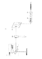
図1に、本発明の第1の実施形態に係る放射線撮像装置の構成を示す。図1に示すように、この放射線撮像装置は、被写体にX線を照射することにより、被写体に関する放射線画像情報を表す検出データを出力する撮像部1と、検出データに基づいて位相情報を復元することにより画像データを生成する画像構成部2と、画像データに基づいて可視画像を表示する表示部3と、可視画像をフィルム等にプリント出力する出力部4とを有している。
【0027】
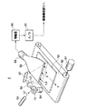
図2は、撮像部1の構成を示す模式図である。撮影部1は、X線源11と、モノクロメータ12と、センサ13とを有している。X線源11は、シンクロトロン放射光を利用し、モノクロメータ12で放射光からのX線の所定の波長成分だけを回折することにより、単色X線としている。なお、X線源11としては、コヒーレント性及び単色性が高いビームを発生することができるX線源を用いることが望ましい。ここで、単色性が高いビームとは、主に単一波長を有するビームのことをいうが、厳密に単一波長である必要はない。このため、本実施形態においては、X線源11として、X線を発生するシンクロトロン放射光を用いている。シンクロトロン放射光とは、磁場中で電子を円運動させたり螺旋運動させたりすることによって発生する電磁波のことをいう。このような放射光源においては、電子の求心加速度を変更することにより、発生するX線の波長を変更することができる。X線源11から発生したX線は、被写体10を透過し、センサ13に入射して回折縞を生じる。なお、以下において、被写体10とセンサ13との距離を、撮像距離といい、本実施形態においては、図3に示すように、同一撮像距離で、異なる波長λ0及びλ1の2種類のX線を発生させている。
【0028】
センサ13は、X線を入射させて回折縞を生じさせるためのスクリーンとして用いられ、センサ13の各位置に入射した回折光の強度を表す検出信号を出力する。センサ13としては、例えば、CCD(coupled charge device)等のように、入射したX線の強度を電気信号に変換して出力する複数の検出素子を有する2次元センサが用いられる。
【0029】
また、撮像部1は、増幅器14と、A/D変換器15とを有している。増幅器14は、センサ13から出力された検出信号を増幅する。A/D変換器15は、増幅器14によって増幅された検出信号をディジタル信号(「画像信号」又は「検出データ」という)に変換し、検出データを画像構成部2に出力する。
【0030】
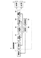
再び図1を参照すると、画像構成部2は、撮像部1から出力された検出データを一時的に記憶する記憶部21と、撮像距離が等しく波長の異なる2種類のX線によって得られた2つの検出データに基づいて位相のラプラシアンに相当する値を算出するラプラシアン処理部22と、位相復元を行うための逆ラプラシアン演算を行う逆ラプラシアン処理部23と、復元された位相情報に基づいて画像データを生成する画像処理部24と、上記の各部21〜24及び撮像部1におけるX線の波長を制御する制御部25とを有している。画像構成部2は、ディジタル回路で構成しても良いし、ソフトウェアとCPUで構成しても良い。その場合には、CPUを含む制御部25が、記録媒体26に記録された放射線撮像プログラムに基づいて検出データを処理する。記録媒体26としては、フレキシブルディスク、ハードディスク、MO、MT、RAM、CD−ROM、又はDVD−ROM等が該当する。
【0031】
表示部3は、例えば、CRT等のディスプレイ装置であり、画像構成部2によって復元された位相情報を表す画像データに基づいて可視画像を表示する。また、出力部4は、例えば、レーザプリンタであり、画像データに基づいて可視画像をフィルム等にプリント出力する。
【0032】
次に、X線源11で発生するX線の波長(エネルギー)と被写体10による透過率との関係について説明する。ここで、被写体10は、図2に示すように、厚みdを有することとする。被写体10の厚みをd、屈折率をn=1−δ−iβ(iは虚数単位)で表すこととすると、被写体10の透過直後のX線φOUTは、被写体10の透過直前のX線φINを用いて、次のように表される。
【数8】
【0033】
したがって、被写体10の透過直後のX線の強度IOUTは、被写体10の透過直前のX線の強度IINを用いて、次のように表される。
【数9】
![]()
【数10】
次に、被写体10として乳房を想定する。図4は、X線エネルギーの関数としての透過率を示している。但し、標準的な脂肪の組成を想定してβを定め、被写体10の厚みをd=5cmとしている。図4に示すように、エネルギーが低いほど、透過率が急激に減少する。したがって、非特許文献3で用いられたX線エネルギー(E=3.3keV、1.7keV、5.0keV)では、乳房等の厚みを有する被写体を撮影する際には不適であった。また、高透過率でエネルギー効率を良くするためには10%程度の透過率となる22keV程度のX線エネルギーが望ましいが、被写体10によるX線吸収量(被爆量)を抑え、センサ13にX線を到達させるためには、少なくとも1%以上の透過率となる16keV以上のX線エネルギーが必要である。
【0035】
一方、位相コントラスト法は、図2における被写体10とセンサ13とを所定の距離だけ離すことにより、位相変化を検出する撮像法である。被写体10によるX線の位相変化は、式(8)のe-ik(1-δ)dとして表される。ここで、被写体が真空(δ=0)の場合におけるX線の位相変化e-ikdを基準にすると、被写体10によるX線の位相変化はeikδdと表される。なお、位相は指数の肩に乗っているkδdである。
【0036】
ここで、δはX線のエネルギー依存性を持つため、図5に、標準的な脂肪の組成を想定した場合のδdとエネルギーとの関係を示す。但し、d=5cmとしている。
【0037】
ところで、式(4)に示した位相推定の際に基本となるTIEを簡単のために1次元で考え、符号を無視し、更に、位相φ=kδdを入れて整理すると、次のように表される。
【数11】
ここで、左辺は、X線の強度Iが距離zによってどれだけ変化するかを強度Iに対する割合として表した値であり、実験によって求められる値はせいぜい1%(|(1/I)×(∂I/∂z)|≧10-2)である。また、右辺は、δdの値が局所的にどれだけ変化したのかに依存する値であり、診断目的としては、10μm(=10-5m)のうちに10-6ラジアン程度の位相変化の検出が望ましい。したがって、式(12)の右辺は次のように表される。
【数12】
また、式(12)の左辺に−(1/I)×(∂I/∂z)≧10-2を代入して整理すると、次のように表される。
【数13】
再び、図5を参照すると、dδ≧10-6となるのは、X線エネルギーが、およそ30keV以下の場合である。以上より、16keV以上30keV以下のエネルギーを有するX線を用いて撮影を行うことが望ましい。
【0041】
次に、図1、図3及び図6を参照しながら、本発明の第1の実施形態に係る放射線撮像方法について説明する。図6は、本発明の第1の実施形態に係る放射線撮像方法を示すフローチャートである。本実施形態においては、図3に示すように、同一撮像距離で、異なる波長λ0及びλ1のX線を用いて撮像された2枚の回折縞画像を表す検出データに基づいて、位相コントラスト法を用いて可視画像を構成する。なお、波長λ0又はλ1のX線とは、波長λ0又はλ1を中心波長とする単色性の高いX線のことをいい、厳密に波長λ0又はλ1の単一波長のX線でなくても良い。但し、波長λ0又はλ1のX線のエネルギーの中心値が16keV以上30keV以下の条件を満たすこととする。
【0042】
まず、ステップS10において、X線撮像を行う。即ち、図3に示すように、撮像距離がRとなる位置にセンサ13を配置し、被写体10に波長λ0のX線を照射することによりX線撮像を行う。次に、被写体10に波長λ1のX線を照射することによりX線撮像を行う。これにより、回折縞画像を表す検出データが得られる。
【0043】
ステップS10におけるX線撮像により、検出データI(r⊥,R,λ0)、I(r⊥,R,λ1)が、画像構成部2に順次入力される。ここで、検出データI(r⊥,R,λ0)は、撮像距離R面上の位置r⊥=(x,y)における波長λ0の回折光の強度を表す。同様に、検出データI(r⊥,R,λ1)は、撮像距離R面上の位置r⊥=(x,y)における波長λ1の回折光の強度を表す。これらの検出データは、画像構成部2の記憶部21に順次記憶される。
【0044】
次に、ステップS11及びS12において、画像構成部2は、記憶部21に記憶されている検出データI(r⊥,R,λ0)及びI(r⊥,R,λ1)に基づいて、被写体を透過した直後のX線の位相φ(r⊥,0,λ0)を復元する。
まず、ステップS11において、ラプラシアン処理部22は、記憶部21に記憶されている検出データに基づいて、次式(16)を用いて位相φ(r⊥,0,λ0)のラプラシアンf(r⊥,0,λ0)=∇2φ(r⊥,0,λ0)を求める。
【数14】
g0=ln[I(r⊥,R,λ0)]・・・(17)
g1=ln[I(r⊥,R,λ1)]・・・(18)
Δλ=λ1−λ0、σ=λ1/λ0
である。
【0045】
従って、検出データI(r⊥,R,λ0)及びI(r⊥,R,λ1)を式(17)及び式(18)にそれぞれ代入してg0及びg1を求め、さらに、g0及びg1を式(16)に代入することにより、位相のラプラシアンf(r⊥,0,λ0)が求められる。
【0046】
さらに、ステップS12において、逆ラプラシアン処理部24は、ステップS11において求められた位相のラプラシアンf(r⊥,0,λ0)=∇2φ(r⊥,0,λ0)に対して逆ラプラシアン演算を行うことにより、位相φ(r⊥,0,λ0)を得る。ここで、逆ラプラシアン演算について、詳しく説明する。f(r⊥,0,λ0)のフーリエ変換は、次式(19)のように表される。
【数15】
![]()
【0047】
これより、位相φ(r⊥,0,λ0)は式(20)のように表される。
【数16】
【0048】
この式(20)を利用することにより、逆ラプラシアン演算を行うことができる。即ち、f(r⊥,0,λ0)をフーリエ変換し、{−4π2(u2+v2)}-1を掛け、さらに、これを逆フーリエ変換することにより、復元された位相φ(r⊥,0,λ0)が得られる。
【0049】
ここで、|u|及び|v|が所定の値以下となる範囲内で{−4π2(u2+v2)}-1を予め算出しておき、式(20)に示す演算を行う際にこれを利用しても良い。即ち、所定の値constを設定すると、|u|,|v|≦constの場合には、式(20)において次式の値を用いる。
{−4π2(u2+v2)}-1=(予め算出された値)
また、|u|,|v|>constの場合には、式(20)において、次式の値を用いる。
{−4π2(u2+v2)}-1=0
これにより、逆ラプラシアン演算を高速に行うことができる。
【0050】
次に、ステップS13において、画像処理部24は、位相φ(r⊥,0,λ0)に基づいて画像データを生成する。すなわち、画像処理部24は、それぞれの画素における位相φ(r⊥,0,λ0)を、明度を表すデータに変換すると共に、階調処理や補間処理等の必要な画像処理を施す。
【0051】
その後、必要に応じて、ステップS14において、表示部3は、画像データに基づく可視画像をディスプレイに表示したり、ステップ15において、出力部4が、それをフィルム等に印刷する。
【0052】
また、本実施形態においては、被写体を撮像する際にX線を用いているが、被写体を透過して回折像を形成することができ、16keV以上30keV以下のエネルギー条件を満たす放射線であればX線に限らず用いることができる。例えば、電子線を含む粒子線等が挙げられる。また、本実施形態においては、エネルギーの異なる2つのX線を用いて位相を復元したが、非特許文献3に述べれられているように、エネルギーの異なる3つのX線を用いて位相を復元しても良い。
【0053】
さらに、本実施形態においては、被写体を撮像する際に放射光源を用いているが、放射光ではないビームを発生するX線源を用いても良い。例えば、立命館大学が開発した電子蓄積型高輝度硬X線発生装置は、卓上型でありながら放射光並みに輝度及び指向性の高いX線を発生することができる。この装置が発生するX線はコヒーレント性を有しており、また、単一波長ではないが、単色化結晶と組み合わせることにより単色化することが可能である。また、技術研究組合フェムト秒テクノロジー研究機構(FESTA)が開発した線源は、逆コンプトン散乱の原理に基づいて極短パルス高輝度X線を発生する。この線源は、小型で持ち運びが可能であり、干渉性を有すると共に、指向性及び単色性の高いX線を発生することができる。なお、X線源として点放射線源を用いる場合には、画像構成部においてデータ処理を行う際に、拡大率を含めて補正することが望ましい。
【0054】
次に、本発明の第1の実施形態に係る放射線撮像装置の変形例について、図7を参照しながら説明する。図7に示す放射線撮像装置は、撮影部5及び読取り部6を有している。その他の構成については、図1に示す放射線撮像装置と同様である。
【0055】
撮像部5においては、画像情報を記録するために用いられるスクリーンとして、図2に示す撮像部1におけるセンサ13の替わりに、輝尽性蛍光体シート(記録シート)が用いられる。
【0056】
輝尽性蛍光体(蓄積性蛍光体)とは、放射線等を照射するとその放射線エネルギの一部が蓄積され、その後、可視光等の励起光を照射すると、蓄積されたエネルギに応じて輝尽発光する物質である。この輝尽性蛍光体を塗布したシートに人体等の被写体の放射線画像を撮像記録し、この輝尽性蛍光体シートをレーザ光等の励起光で走査すると輝尽発光光が生じるので、この光を光電的に読み取ることにより検出データを得ることができる。この検出データを適切に処理した後、CRT等のディスプレイに出力したり、レーザプリンタ等によりフィルムに印刷して、放射線画像を可視画像として表示することができる。
【0057】
図7に示す読取り部6は、記録シートに記録された放射線画像を読み取るために用いられる。ここで、図8を参照しながら、読取り部6の構成及び動作について説明する。画像情報が記録された記録シート50は、読取り部6の所定位置にセットされる。記録シート50は、モータ51により駆動されるシート搬送手段52により、Y軸方向に搬送される。一方、レーザ光源53より出射したビームL1は、モータ54により駆動されて矢印方向に高速回転する回転多面鏡55により反射偏向され、収束レンズ56を通過する。その後、ビームL1は、ミラー57により光路を変えて、記録シート50をX軸方向に走査する。この走査により、励起光L2が記録シート50に照射され、照射された部分からは蓄積記録されている放射線画像情報に応じた光量の輝尽発光光L3が発散される。輝尽発光光L3は、光ガイド58により導かれ、フォトマルチプライヤ(光電子増倍管)59により光電的に検出される。フォトマルチプライヤ59から出力されたアナログ信号は、増幅器60により増幅され、A/D変換器61によりディジタル化される。A/D変換器61から出力された検出データは、画像構成部2に入力される。
【0058】
撮像部5において、出射するX線のエネルギーを変えて複数枚の記録シートを用いて放射線撮像を行い、読取り部6において、それぞれの記録シートから画像情報を読み取ることにより、異なるX線のエネルギーにおいて得られた複数の干渉縞画像を表す検出データが得られる。画像構成部2は、この検出データに基づいて位相復元を行い、画像データを生成する。画像構成部2における処理については、図6を用いて説明したのと同様である。
【0059】
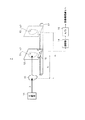
次に、本発明の第2の実施形態に係る放射線撮像装置について説明する。図9に、本発明の第2の実施形態に係る放射線撮像装置の構成を示す。
図9に示すように、この放射線撮像装置は、被写体にX線を照射することにより、被写体に関する放射線画像情報を表す検出データを出力する撮像部7と、検出データに基づいて位相情報を復元することにより画像データを生成する画像構成部8とを有している。その他の構成については、図1におけるのと同様である。
【0060】
図10は、撮像部7の構成を示す模式図である。撮影部7は、X線源11と、センサ13とを有している。X線源11から発生したX線は、被写体10を透過し、センサ13に入射して回折縞を生じる。
【0061】
センサ13は、保持部16によって保持されている。保持部16は、レール17上に移動可能な状態で支持されている。保持部16の位置は、後述する画像構成部8の制御部によって制御されており、この制御によって被写体10とセンサ13との撮像距離が変更される。
【0062】
また、撮像部7は、増幅器14と、A/D変換器15とを有している。増幅器14は、センサ13から出力された検出信号を増幅する。A/D変換器15は、増幅器14によって増幅された検出信号をディジタル信号(「画像信号」又は「検出データ」という)に変換し、検出データを画像構成部8に出力する。
【0063】
再び、図9を参照すると、画像構成部8は、撮像部7から出力された検出データを一時記憶する記憶部81と、撮像距離の異なる検出データの間における差分係数を求める差分処理部82と、位相のラプラシアンに相当する値を演算するラプラシアン処理部83と、位相復元を行うための逆ラプラシアン演算を行う逆ラプラシアン処理部84と、逆ラプラシアン処理部84から出力されたセンサ位置における位相情報に基づいて画像データを生成する画像処理部85と、上記の各部81〜85及び撮像部7における撮像距離を制御する制御部86とを有している。画像構成部8は、ディジタル回路で構成しても良いし、ソフトウェアとCPUで構成しても良い。その場合には、CPUを含む制御部86が、記録媒体87に記録された放射線撮像プログラムに基づいて検出データを処理する。記録媒体87としては、フレキシブルディスク、ハードディスク、MO、MT、RAM、CD−ROM、又はDVD−ROM等が該当する。
【0064】
次に、本発明の第2の実施形態に係る放射線撮像方法について、図9〜図11を参照しながら説明する。図11は、本発明の第2の実施形態に係る放射線撮像方法を示すフローチャートである。本実施形態においては、単一波長のX線を用い、異なる撮像距離z0及びz1 において、同一波長λのX線を用いて撮像された2枚の回折縞画像を示す画像情報を用いて可視画像を生成する。なお、波長λのX線とは、波長λを中心波長とする単色性の高いX線のことをいい、厳密に波長λの単一波長のX線でなくても良い。但し、波長λのX線のエネルギーの中心値が16keV以上30keV以下の条件を満たすこととする。
【0065】
まず、ステップS20において、X線源によって生成されるX線の波長をλに設定し、センサ13の位置を変更しながらX線撮像を行う。即ち、図10に示すように、まず、撮像距離がz0となる位置にセンサ13を配置し、被写体10にX線を照射することによりX線撮像を行う。続いて、撮像距離がz1となる位置にセンサ13を移動させ、同様にX線撮像を行う。これにより、回折縞画像を表す画像情報が得られる。
【0066】
ステップS20におけるX線撮像により、検出データI(r⊥,z0,λ)、I(r⊥,z1,λ)が、画像構成部8に順次入力される。ここで、検出データI(r⊥,z0,λ)は、撮像距離z0面上の位置r⊥=(x,y)における回折光の強度を表す。同様に、検出データI(r⊥,z1,λ)は、撮像距離z1面上の位置r⊥=(x,y)における回折光の強度を表す。これらの検出データは、画像構成部8の記憶部81に順次記憶される。
【0067】
次に、ステップS21〜S23において、画像構成部8は、記憶部81に記憶されている検出データに基づいてセンサ位置における位相を復元する。
まず、ステップS21において、差分処理部82は、次式(21)を用いて検出データI(r⊥,z1,λ)と検出データI(r⊥,z0,λ)との差分係数を求める。
【数17】
次に、ステップS22において、ラプラシアン処理部83は、ステップS21において求められた差分係数と、記憶部21に記憶されている検出データとに基づいて、次式(22)を用いて位相のラプラシアンf(r⊥,z,λ)=∇2φ(r⊥,z,λ)を求める。
【数18】
【0069】
さらに、ステップS23において、逆ラプラシアン処理部84は、ステップS82において求められた位相のラプラシアンf(r⊥,z,λ)=∇2φ(r⊥,z,λ)について逆ラプラシアン演算を行うことにより、位相φ(r⊥,z,λ)を算出する。
【0070】
したがって、位相φ(r⊥,z,λ)は式(23)のように表される。
【数19】
この式(23)を利用することにより、逆ラプラシアン演算を行うことができる。即ち、f(r⊥,z,λ)をフーリエ変換し、{−4π2(u2+v2)}-1を掛け、さらに、これを逆フーリエ変換することにより、復元された位相φ(r⊥,z,λ)が得られる。
【0072】
次に、ステップS24において、画像処理部85は、位相φ(r⊥,z,λ)に基づいて画像データを生成する。すなわち、画像処理部85は、それぞれの画素における位相φ(r⊥,z,λ)を、明度を表すデータに変換すると共に、階調処理や補間処理等の必要な画像処理を施す。
【0073】
その後、必要に応じて、ステップS25において、表示部3は、画像データに基づく可視画像をディスプレイに表示したり、ステップ26において、出力部4が、それをフィルム等に印刷する。
【0074】
【発明の効果】
本発明によれば、位相コントラスト法により人体等の生体の放射線画像を構成する際に、16keV以上30keV以下の透過率の高いエネルギーの放射線を用いることにより、位相の推定精度を高めることができる。
【図面の簡単な説明】
【図1】本発明の第1の実施形態に係る放射線撮像装置の構成を示す図である。
【図2】図1に示す撮像部の構成を示す模式図である。
【図3】同一撮像距離で、異なる波長λ0及びλ1の2種類のX線を発生させている撮像部を示す図である。
【図4】X線エネルギーの関数として透過率を示す図である。
【図5】δdとエネルギーとの関係を示す図である。
【図6】本発明の第1の実施形態に係る放射線撮像方法を示すフローチャートである。
【図7】本発明の第1の実施形態に係る放射線撮像装置の変形例を示す図である。
【図8】図7に示す読み取り部の構成を示す図である。
【図9】本発明の第2の実施形態に係る放射線撮像装置の構成を示す図である。
【図10】図9に示す撮像部7の構成を示す模式図である。
【図11】本発明の第2の実施形態に係る放射線撮像方法を示すフローチャートである。
【図12】位相復元の原理を説明するための図である。
【図13】位相復元の原理を説明するための図である。
【符号の説明】
1、5、7 撮像部
2、8 画像構成部
3 表示部
4 出力部
6 読取り部
10、100 被写体
11 X線源
12 モノクロメータ
13 センサ
14 増幅器
15 A/D変換器
16 保持部
17 レール
21、81 記憶部
22、83 ラプラシアン処理部
23、84 逆ラプラシアン処理部
24、85 画像処理部
25、86 制御部
26、87 記録部
50 輝尽性蛍光体シート(記録シート)
51 モータ
52 シート搬送手段
53 レーザ光源
54 モータ
55 回転多面鏡
56 収束レンズ
57 ミラー
58 光ガイド
59 フォトマルチプライヤ(光電子増倍管)
82 差分処理部
101 物体面
102 スクリーン[0001]
BACKGROUND OF THE INVENTION
The present invention relates to a radiation imaging method, a radiation imaging apparatus, and a radiation imaging program used for constructing an image based on image information obtained by radiation imaging. In addition, in this application, in addition to X-rays, (alpha) rays, (beta) rays, and (gamma) rays, a radiation shall mean the broad radiation including particle beams, such as an electron beam, and electromagnetic waves.
[0002]
[Prior art]
Conventionally, an imaging method using X-rays or the like has been used in various fields, and particularly in the medical field, has become one of the most important means for diagnosis. Since the first X-ray photography was realized, the X-ray photography method has been improved many times, and at present, a method combining a fluorescent screen and an X-ray film has become mainstream. On the other hand, in recent years, various digitized apparatuses such as X-ray CT, ultrasound, and MRI have been put into practical use, and the construction of diagnostic information processing systems and the like in hospitals is being promoted. For X-ray images, much research has been done to digitize imaging systems. By digitizing the imaging system, it is possible to store a large amount of data for a long period of time without causing deterioration of image quality, which is useful for the development of a medical diagnosis information system.
[0003]
By the way, the radiographic image obtained in this way is generated by converting the intensity of radiation transmitted through the subject into the brightness of the image. For example, when imaging a region including a bone part, radiation that has passed through the bone part is greatly attenuated, and radiation that has passed through a part other than the bone part, that is, the soft part is attenuated slightly. In this case, since the intensity difference between the radiation transmitted through different tissues is large, a high-contrast radiation image can be obtained.
[0004]
On the other hand, for example, when imaging a soft part region such as a breast, radiation is easily transmitted through the soft part as a whole, and therefore, a difference in tissue in the soft part hardly appears as an intensity difference of transmitted radiation. For this reason, only a low-contrast radiation image can be obtained for the soft part. Thus, the conventional radiation imaging method is not appropriate as a method for visualizing a slight tissue difference in the soft part.
[0005]
Here, the information included in the radiation transmitted through the subject includes phase information in addition to the intensity information. In recent years, a phase contrast method for generating an image using this phase information has been studied. The phase contrast method is an image construction technique for converting a phase difference caused by transmission of X-rays or the like through a subject into image brightness.
[0006]
The phase contrast method uses interference generated by using an interferometer or zone plate.X-rayTo obtain the phase difference based on theX-rayThere is a method for obtaining a phase difference based on the above. Of these, diffractionX-rayThe diffraction method for obtaining the phase difference based on the above obtains the phase difference based on the following principle. For example, X-rays propagate through a substance as waves travel in the same way as light. The propagation speed varies depending on the refractive index of the substance. For this reason, when X-rays with the same phase are irradiated toward the subject, a difference occurs in the way the X-rays are transmitted due to the difference in tissue in the subject. As a result, the wavefront of the X-ray transmitted through the subject is distorted, so that diffraction fringes are generated in the X-ray image obtained based on the transmitted X-ray. The diffraction fringe pattern differs depending on the distance between the screen on which the X-ray is imaged and the subject and the wavelength of the X-ray. Therefore, by analyzing two or more X-ray images having different diffraction fringe patterns, the phase difference of X-rays generated at each position on the screen can be obtained. By converting this phase difference into lightness, an X-ray image in which the difference in tissue in the subject appears clearly can be obtained.
[0007]
In particular, in the radiation after passing through the soft part of the subject, the phase difference is larger than the intensity difference in the transmitted radiation due to the difference in the transmitted tissue. Differences can be visualized. In order to use such a phase contrast method, imaging conditions in radiation imaging and techniques for restoring the phase from a diffraction fringe pattern are being studied.
[0008]
Non-Patent
[Expression 1]
Next, the principle of phase restoration will be described with reference to FIG. As shown in FIG. 12, an X-ray having a wavelength λ is from the left side of the figure.EnterAnd is transmitted through the
[Expression 2]
[0010]
However, since it is difficult to solve such a TIE, the TIE has been mainly used in an approximate manner. Non-Patent Document 2 below describes that an X-ray image is formed by performing phase restoration based on image information obtained by hard X-ray imaging. In this document, the TIE shown in Equation (1) is approximated as follows. First, formula (1) is developed. In the following, the vector r in the above document is rewritten to the (x, y) component.
[Equation 3]
When the second term on the right side of Equation (3) is approximated to zero, the approximate equation shown in Equation (4) below is obtained.
[Expression 4]
[0012]
Non-Patent
[0013]
In this case, r⊥= (X, y), wavelength λ0X-ray intensity I (r immediately after passing through the subject 100⊥, 0, λ0) And phase φ (r⊥, 0, λ0) And wavelength λmDetected on screen 102X-rayStrength I (r⊥, R, λm) With the following relationship. However, in the following equation (5), I (r⊥, 0, λ0) = Exp {-M (r⊥, 0, λ0)}.
[Equation 5]
In Expression (5), ∇M · ∇φ (r⊥, R, λm) Is sufficiently small, it can be approximated as follows.
[Formula 6]
Furthermore, from the equation (6), the intensity and phase of the X-ray immediately after passing through the subject 100 are expressed as follows.
[Expression 7]
Laplacian of phase in equation (8)2φ (r⊥, R, λ0) To obtain the phase φ (r⊥, R, λ0). Furthermore, a visible image representing the subject can be obtained by converting this phase into lightness in the image. As described above, by using Expression (8), it is possible to easily perform a calculation for phase restoration based on a small number of radiation images obtained by changing the wavelength. Therefore, in
[0016]
However, at these wavelengths, the X-ray absorption when passing through the subject is too large, so it is possible to photograph a thin subject, but when photographing a subject having a thickness such as a human breast or breast. Had the problem of being unsuitable.
[0017]
[Non-Patent Document 1]
Allman et al. “Noninterferometric quantitative phase imaging with soft x rays”, J. Optical Society of America A, Vol. 17, No. 10 (October 2000), p. 1732-1743
[Non-Patent Document 2]
TE Gureyev et al. “Hard X-ray quantitative non-interferometric phase-contrast imaging”, Optical Photography Research Specialist (SPIE) Vol. 3659 (1999), p. . 356-364
[Non-Patent Document 3]
TE Gureyev et al. “Quantitative In-Line Phase-Contrast Imaging with Multienergy X Rays”, Physical Review Letter Vol. 86, No. 25 ( 2001), p. 5827-5830
[0018]
[Problems to be solved by the invention]
Therefore, in view of the above points, the present invention provides a living body or the like by the phase contrast method.bodyAn object of the present invention is to provide a radiation imaging method capable of improving the phase estimation accuracy by using radiation with high transmittance when constructing the radiation image. It is another object of the present invention to provide a radiation imaging apparatus using such a radiation imaging method and a radiation imaging program.
[0021]
[Means for Solving the Problems]
To solve the above issues,The radiation imaging apparatus according to the first aspect of the present invention is based on detection data obtained by detecting the intensity of radiation transmitted through a subject.Using the basic equation TIE for phase restorationA radiation imaging apparatus that restores phase information of radiation that has passed through a subject, a light source that generates a plurality of radiations having energy different from 16 keV to 30 keV, and a radiation source that is generated from the light source and passes through the subject. Based on a plurality of detection data obtained by detecting the intensity of a plurality of radiations having different wavelengths transmitted through the subject, and detection means for obtaining detection data representing radiation image information by detecting the intensity,By calculating the Laplacian of the phase and performing the inverse Laplacian operation on the Laplacian of the determined phase,Image forming means for obtaining phase data by restoring phase information of radiation transmitted through the subject and generating image data based on the phase data;
[0022]
The radiation imaging apparatus according to the second aspect of the present invention is based on detection data obtained by detecting the intensity of radiation that has passed through the subject.Using the basic equation TIE for phase restorationA radiation imaging apparatus that restores phase information of radiation that has passed through a subject, a light source that generates radiation having a predetermined wavelength with an energy of 16 keV or more and 30 keV or less, and an intensity of radiation that is generated from the light source and passes through the subject Detecting means for obtaining detection data representing radiation image information, driving means used for changing the distance between the subject and the detecting means, and the intensity of the radiation transmitted through the subject at different distances Based on a plurality of detection data obtained by detecting,By calculating the Laplacian of the phase and performing the inverse Laplacian operation on the Laplacian of the determined phase,Image forming means for obtaining phase data by restoring phase information of radiation transmitted through the subject and generating image data based on the phase data;
[0023]
A radiation imaging program according to the first aspect of the present invention is:Radiation sourceA radiation imaging program for restoring phase information of radiation transmitted through a subject based on detection data obtained by generating radiation and detecting the intensity of radiation transmitted through the subject,Radiation sourceAnd a plurality of detection data obtained by detecting the intensity of the radiation having different wavelengths transmitted through the subject and the procedure (a) for generating radiation having different wavelengths whose energy is 16 keV or more and 30 keV or less Based on this, the CPU executes a procedure (b) for obtaining a phase Laplacian and a procedure (c) for obtaining phase data by performing an inverse Laplacian operation on the phase Laplacian.
[0024]
Furthermore, a radiation imaging program according to the second aspect of the present invention provides:Radiation sourceA radiation imaging program that restores phase information of radiation transmitted through a subject based on detection data obtained by detecting radiation intensity that has generated more radiation and transmitted through the subject,Radiation sourceAnd a plurality of detection data obtained by detecting the intensity of the radiation transmitted through the subject at different distances, and the procedure (a) for generating radiation having a predetermined wavelength whose energy is 16 keV or more and 30 keV or less Based on this, the CPU executes a procedure (b) for obtaining a phase Laplacian and a procedure (c) for obtaining phase data by performing an inverse Laplacian operation on the phase Laplacian.
[0025]
According to the present invention, when a radiological image of a human body or the like is constructed by the phase contrast method, the phase estimation accuracy can be increased by using radiation having high transmittance.
[0026]
DETAILED DESCRIPTION OF THE INVENTION
Hereinafter, embodiments of the present invention will be described with reference to the drawings. The same constituent elements are denoted by the same reference numerals, and the description thereof is omitted.
FIG. 1 shows a configuration of a radiation imaging apparatus according to the first embodiment of the present invention. As shown in FIG. 1, this radiation imaging apparatus irradiates a subject with X-rays, thereby outputting detection data representing radiation image information about the subject, and restoring phase information based on the detection data. Thus, it has an image construction unit 2 that generates image data, a
[0027]
FIG. 2 is a schematic diagram illustrating the configuration of the
[0028]
The
[0029]
The
[0030]
Referring to FIG. 1 again, the image construction unit 2 is obtained by the
[0031]
The
[0032]
next,X-ray sourceThe relationship between the wavelength (energy) of X-rays generated at 11 and the transmittance of the subject 10 will be described. Here, it is assumed that the subject 10 has a thickness d as shown in FIG. Assuming that the thickness of the subject 10 is d and the refractive index is n = 1−δ−iβ (i is an imaginary unit), the X-ray φ immediately after the transmission of the subject 10OUTIs the X-ray φ immediately before the transmission of the subject 10INIs expressed as follows.
[Equation 8]
[0033]
Therefore, the intensity I of the X-ray immediately after transmission through the subject 10OUTIs the intensity I of the X-ray just before transmission of the subject 10INIs expressed as follows.
[Equation 9]
![]()
[Expression 10]
Next, a breast is assumed as the subject 10. FIG.IsAs a function of X-ray energyofShows transmittanceis doing. However, β is determined assuming a standard fat composition, and the thickness of the subject 10 is d = 5 cm. As shown in FIG. 4, the lower the energy, the sharper the transmittance decreases. Therefore, the X-ray energy (E = 3.3 keV, 1.7 keV, 5.0 keV) used in
[0035]
On the other hand, the phase contrast method is an imaging method for detecting a phase change by separating the subject 10 and the
[0036]
Here, since δ has energy dependence of X-rays, FIG. 5 shows the relationship between δd and energy when a standard fat composition is assumed. However, d = 5 cm.
[0037]
By the way, the TIE that is fundamental in the phase estimation shown in the equation (4) is considered in one dimension for the sake of simplicity, the sign is ignored, and further, the phase φ = kδd is put in order and arranged, the following table is obtained. Is done.
[Expression 11]
Here, the left side is a value representing how much the intensity I of the X-ray changes with the distance z as a ratio to the intensity I, and the value obtained by the experiment is 1% (| (1 / I) × ( ∂I / ∂z) | ≧ 10-2). Further, the right side is a value that depends on how much the value of δd has changed locally. For the purpose of diagnosis, 10 μm (= 10-Fivem)-6Detection of phase changes on the order of radians is desirable. Therefore, the right side of Expression (12) is expressed as follows.
[Expression 12]
Further, − (1 / I) × (∂I / ∂z) ≧ 10 on the left side of Expression (12)-2When substituting and rearranging, it is expressed as follows.
[Formula 13]
Referring again to FIG. 5, dδ ≧ 10-6This is the case when the X-ray energy is about 30 keV or less. From the above, it is desirable to perform imaging using X-rays having energy of 16 keV to 30 keV.
[0041]
Next, a radiation imaging method according to the first embodiment of the present invention will be described with reference to FIG. 1, FIG. 3, and FIG. FIG. 6 is a flowchart showing the radiation imaging method according to the first embodiment of the present invention. In this embodiment, as shown in FIG. 3, at the same imaging distance, different wavelengths λ0And λ1A visible image is constructed using a phase contrast method based on detection data representing two diffraction fringe images captured using X-rays. The wavelength λ0Or λ1X-rays have a wavelength of λ0Or λ1X-ray with high monochromaticity centered on0Or λ1The single-wavelength X-rays may not be used. However, wavelength λ0Or λ1The center value of the energy of X-rays satisfies the condition of 16 keV or more and 30 keV or less.
[0042]
First, in step S10, X-ray imaging is performed. That is, as shown in FIG. 3, the
[0043]
By the X-ray imaging in step S10, the detection data I (r 撮 像, R, λ0), I (r⊥, R, λ1) Are sequentially input to the image construction unit 2. Here, the detection data I (r⊥, R, λ0) Is the wavelength λ at the position r⊥ = (x, y) on the imaging distance R plane.0Represents the intensity of the diffracted light. Similarly, the detection data I (r⊥, R, λ1) Is the wavelength λ at the position r⊥ = (x, y) on the imaging distance R plane.1Represents the intensity of the diffracted light. These detection data are sequentially stored in the
[0044]
Next, in steps S11 and S12, the image construction unit 2 detects the detection data I (r⊥, R, λ) stored in the
First, in step S11, the
[Expression 14]
g0= Ln [I (r⊥, R, λ0]] ... (17)
g1= Ln [I (r⊥, R, λ1]] ... (18)
Δλ = λ1−λ0, Σ = λ1/ Λ0
It is.
[0045]
Therefore, the detection data I (r⊥, R, λ0) And I (r⊥, R, λ)1) Is substituted for equations (17) and (18), respectively, and g0And g1And then g0And g1Is substituted into equation (16) to obtain the phase Laplacian f (r⊥, 0, λ0) Is required.
[0046]
Further, in step S12, the inverse
[Expression 15]
![]()
[0047]
From this, the phase φ (r⊥, 0, λ0) Is expressed as in equation (20).
[Expression 16]
[0048]
By using this equation (20), inverse Laplacian calculation can be performed. That is, f (r⊥, 0, λ0) To Fourier transform, {-4π2(U2+ V2)}-1, And inverse Fourier transform this to restore the restored phase φ (r⊥, 0, λ0) Is obtained.
[0049]
Here, within the range where | u | and | v | are equal to or less than a predetermined value, {−4π2(U2+ V2)}-1May be calculated in advance and used when performing the calculation shown in Equation (20). That is, when the predetermined value const is set, the value of the following expression is used in Expression (20) when | u |, | v | ≦ const.
{-4π2(U2+ V2)}-1= (Pre-calculated value)
In the case of | u |, | v |> const, the value of the following expression is used in Expression (20).
{-4π2(U2+ V2)}-1= 0
Thereby, the inverse Laplacian calculation can be performed at high speed.
[0050]
Next, in step S13, the
[0051]
Thereafter, if necessary, in step S14, the
[0052]
In the present embodiment, X-rays are used to image a subject. However, X-rays can be formed as long as they can pass through the subject and form a diffraction image and satisfy an energy condition of 16 keV to 30 keV. Not limited to lines, it can be used. For example, the particle beam containing an electron beam etc. are mentioned. In this embodiment, the phase is restored using two X-rays having different energies. However, as described in
[0053]
Furthermore, in the present embodiment, radiation is emitted when the subject is imaged.light sourceProduces a beam that is not synchrotron radiationX-ray sourceMay be used. For example, an electron storage type high-intensity hard X-ray generator developed by Ritsumeikan University can generate X-rays with high brightness and directivity similar to synchrotron radiation while being a desktop type. The X-rays generated by this apparatus have coherent properties and are not a single wavelength, but can be monochromatic by being combined with a monochromatic crystal. In addition, a radiation source developed by the Femtosecond Technology Research Organization (FESTA), which generates ultra-short pulse high-intensity X-rays based on the principle of inverse Compton scattering. This radiation source is small and portable, has coherence, and can generate X-rays with high directivity and monochromaticity. In addition,X-ray sourceAsPoint radiation sourceIs used, it is desirable to correct including the enlargement ratio when data processing is performed in the image construction unit.
[0054]
Next, a modification of the radiation imaging apparatus according to the first embodiment of the present invention will be described with reference to FIG. The radiation imaging apparatus illustrated in FIG. 7 includes an
[0055]
In the
[0056]
A stimulable phosphor (accumulative phosphor) is a part of the radiation energy stored when irradiated with radiation, etc., and then irradiated with excitation light such as visible light according to the stored energy. It is a substance that emits light. When a radiation image of a subject such as a human body is imaged and recorded on the sheet coated with the photostimulable phosphor, and this photostimulable phosphor sheet is scanned with excitation light such as laser light, the photostimulated emission light is generated. Detection data can be obtained by photoelectrically reading. After appropriately processing this detection data, it can be output to a display such as a CRT or printed on a film by a laser printer or the like to display a radiation image as a visible image.
[0057]
The
[0058]
The
[0059]
Next, a radiation imaging apparatus according to the second embodiment of the present invention will be described. FIG. 9 shows a configuration of a radiation imaging apparatus according to the second embodiment of the present invention.
As shown in FIG. 9, this radiation imaging apparatus irradiates a subject with X-rays, thereby outputting detection data representing radiation image information related to the subject, and restores phase information based on the detection data. And an image construction unit 8 for generating image data. Other configurations are the same as those in FIG.
[0060]
FIG. 10 is a schematic diagram illustrating the configuration of the
[0061]
The
[0062]
The
[0063]
Referring again to FIG. 9, the image construction unit 8 includes a
[0064]
Next, a radiation imaging method according to the second embodiment of the present invention will be described with reference to FIGS. FIG. 11 is a flowchart showing a radiation imaging method according to the second embodiment of the present invention. In this embodiment,singleWaveLongDifferent imaging distance z using X-rays0And z1 Using X-rays of the same wavelength λUsing the image information indicating the two diffraction fringe images captured, a visible image is obtained.GenerationTo do. Note that the X-ray with the wavelength λ means a highly monochromatic X-ray having the wavelength λ as the central wavelength, and may not be strictly a single wavelength X-ray with the wavelength λ. However, the center value of the energy of the X-ray with the wavelength λ satisfies the condition of 16 keV or more and 30 keV or less.
[0065]
First, in step S20,X-rays generated by an X-ray sourceIs set to λ, and X-ray imaging is performed while changing the position of the
[0066]
Detection data I (r 撮 像, z0, Λ), I (r⊥, z1, Λ) are sequentially input to the image construction unit 8. Here, the detection data I (r⊥, z0, Λ) is the imaging distance z0It represents the intensity of diffracted light at a position r⊥ = (x, y) on the surface. Similarly, the detection data I (r⊥, z1, Λ) is the imaging distance z1It represents the intensity of diffracted light at a position r⊥ = (x, y) on the surface. These detection data are sequentially stored in the
[0067]
Next, in steps S <b> 21 to S <b> 23, the image construction unit 8 restores the phase at the sensor position based on the detection data stored in the
First, in step S21, the
[Expression 17]
Next, in step S22, the Laplacian processing unit 83 uses the following equation (22) based on the difference coefficient obtained in step S21 and the detection data stored in the
[Expression 18]
[0069]
Further, in step S23, the inverse
[0070]
Therefore, the phase φ (r⊥, z, λ) is expressed as in Expression (23).
[Equation 19]
By using this equation (23), inverse Laplacian calculation can be performed. That is, f (r⊥, z, λ) is Fourier-transformed and {−4π2(U2+ V2)}-1And further inversely Fourier transform this to obtain the restored phase φ (r⊥, z, λ).
[0072]
Next, in step S24, the
[0073]
Thereafter, if necessary, in step S25, the
[0074]
【The invention's effect】
According to the present invention, a human body or the like is produced by the phase contrast method.bodyWhen the radiation image is constructed, it is possible to improve the phase estimation accuracy by using radiation with high transmittance of 16 keV or more and 30 keV or less.
[Brief description of the drawings]
FIG. 1 is a diagram showing a configuration of a radiation imaging apparatus according to a first embodiment of the present invention.
FIG. 2 is a schematic diagram illustrating a configuration of an imaging unit illustrated in FIG.
FIG. 3 shows different wavelengths λ at the same imaging distance.0And λ1It is a figure which shows the imaging part which is generating 2 types of X-rays.
FIG. 4 shows transmittance as a function of X-ray energy.
FIG. 5 is a diagram illustrating a relationship between δd and energy.
FIG. 6 is a flowchart showing a radiation imaging method according to the first embodiment of the present invention.
FIG. 7 is a diagram showing a modification of the radiation imaging apparatus according to the first embodiment of the present invention.
8 is a diagram illustrating a configuration of a reading unit illustrated in FIG.
FIG. 9 is a diagram showing a configuration of a radiation imaging apparatus according to a second embodiment of the present invention.
10 is a schematic diagram illustrating a configuration of the
FIG. 11 is a flowchart showing a radiation imaging method according to the second embodiment of the present invention.
FIG. 12 is a diagram for explaining the principle of phase restoration;
FIG. 13 is a diagram for explaining the principle of phase restoration;
[Explanation of symbols]
1, 5, 7 Imaging unit
2, 8 Image composition part
3 Display section
4 Output section
6 Reading unit
10, 100 subjects
11X-ray source
12 Monochromator
13 Sensor
14 Amplifier
15 A / D converter
16 Holding part
17 rails
21, 81 storage unit
22, 83 Laplacian processing section
23, 84 Inverse Laplacian processing section
24, 85 Image processing unit
25, 86 Control unit
26, 87 Recording unit
50 photostimulable phosphor sheet (recording sheet)
51 motor
52 Sheet conveying means
53 Laser light source
54 Motor
55 Rotating polygon mirror
56 Converging lens
57 Mirror
58 Light guide
59 Photomultiplier (photomultiplier tube)
82 Difference processing unit
101 Object surface
102 screens
Claims (4)
エネルギーが16keV以上30keV以下である異なる波長λを有する複数の放射線を発生する放射線源と、
前記放射線源から発生され被写体を透過した放射線の強度を検出することにより、放射線画像情報を表す検出データIを得る検出手段と、
被写体を透過した異なる波長を有する複数の放射線の強度を検出することにより得られた複数の検出データIに基づいて、位相のラプラシアンfを求め、求めた位相のラプラシアンfに対して逆ラプラシアン演算を行うことにより、被写体を透過した放射線の位相情報を復元して位相データφを求め、それらの位相データφに基づいて画像データを生成する画像構成手段と、
を具備する放射線撮像装置。 Using the basic formula TIE of based-out phase recovery on the detected data obtained by detecting the intensity of radiation transmitted through an object, a radiation imaging apparatus for restoring the phase information of the radiation transmitted through an object,
A radiation source for generating a plurality of radiations having different wavelengths λ having an energy of 16 keV to 30 keV;
Detecting means for obtaining detection data I representing radiation image information by detecting the intensity of radiation generated from the radiation source and transmitted through the subject;
Based on a plurality of detection data I obtained by detecting the intensities of a plurality of radiations having different wavelengths transmitted through the subject, a phase Laplacian f is obtained, and an inverse Laplacian operation is performed on the obtained Laplacian f. by performing obtain the phase data phi to restore the phase information of the radiation transmitted through the subject, and image construction means for generating image data based on their phase data phi,
A radiation imaging apparatus comprising:
エネルギーが16keV以上30keV以下である所定の波長λを有する放射線を発生する放射線源と、
前記放射線源から発生され被写体を透過した放射線の強度を検出することにより、放射線画像情報を表す検出データIを得る検出手段と、
被写体と前記検出手段との間の距離zを変更するために用いられる駆動手段と、
被写体を透過した放射線の強度を異なる距離zにおいて検出することにより得られた複数の検出データIに基づいて、位相のラプラシアンfを求め、求めた位相のラプラシアンfに対して逆ラプラシアン演算を行うことにより、被写体を透過した放射線の位相情報を復元して位相データφを求め、それらの位相データに基づいて画像データを生成する画像構成手段と、
を具備する放射線撮像装置。 Using the basic formula TIE of based-out phase recovery on the detected data obtained by detecting the intensity of radiation transmitted through an object, a radiation imaging apparatus for restoring the phase information of the radiation transmitted through an object,
A radiation source for generating radiation having a predetermined wavelength λ having an energy of 16 keV or more and 30 keV or less;
Detecting means for obtaining detection data I representing radiation image information by detecting the intensity of radiation generated from the radiation source and transmitted through the subject;
Drive means used to change the distance z between the subject and the detection means;
A phase Laplacian f is obtained based on a plurality of detection data I obtained by detecting the intensity of radiation transmitted through the subject at different distances z , and an inverse Laplacian operation is performed on the obtained Laplacian f. by obtain the phase data φ restores the phase information of the radiation transmitted through the subject, and image construction means for generating image data based on their phase data,
A radiation imaging apparatus comprising:
前記放射線源を制御し、エネルギーが16keV以上30keV以下である異なる波長を有する放射線を発生させる手順(a)と、
被写体を透過した異なる波長を有する放射線の強度を検出することにより得られた複数の検出データに基づいて、位相のラプラシアンを求める手順(b)と、
位相のラプラシアンに逆ラプラシアン演算を施すことにより位相データを求める手順(c)と、
をCPUに実行させる放射線撮像プログラム。Radiation source radiation generated from using the basic formula TIE of based-out phase recovery on the detected data obtained by detecting the intensity of radiation transmitted through an object, to recover the phase information of radiation transmitted through an object A radiation imaging program,
A step (a) of controlling the radiation source to generate radiation having different wavelengths whose energy is not less than 16 keV and not more than 30 keV;
A step (b) of obtaining a Laplacian of the phase based on a plurality of detection data obtained by detecting the intensity of radiation having different wavelengths transmitted through the subject;
A procedure (c) for obtaining phase data by performing an inverse Laplacian operation on the Laplacian of the phase;
Radiation imaging program for causing CPU to execute.
前記放射線源を制御し、エネルギーが16keV以上30keV以下である所定の波長を有する放射線を発生させる手順(a)と、
被写体を透過した放射線の強度を異なる距離において検出することにより得られた複数の検出データに基づいて、位相のラプラシアンを求める手順(b)と、
位相のラプラシアンに逆ラプラシアン演算を施すことにより位相データを求める手順(c)と、
をCPUに実行させる放射線撮像プログラム。Radiation source radiation generated from using the basic formula TIE of based-out phase recovery on the detected data obtained by detecting the intensity of radiation transmitted through an object, to recover the phase information of radiation transmitted through an object A radiation imaging program,
A step (a) of controlling the radiation source to generate radiation having a predetermined wavelength having an energy of 16 keV or more and 30 keV or less;
A step (b) for obtaining a Laplacian of the phase based on a plurality of detection data obtained by detecting the intensity of the radiation transmitted through the subject at different distances;
A procedure (c) for obtaining phase data by performing an inverse Laplacian operation on the Laplacian of the phase;
Radiation imaging program for causing CPU to execute.
Priority Applications (2)
| Application Number | Priority Date | Filing Date | Title |
|---|---|---|---|
| JP2002285252A JP4137574B2 (en) | 2002-09-30 | 2002-09-30 | Radiation imaging apparatus and radiation imaging program |
| US10/671,786 US7424173B2 (en) | 2002-09-30 | 2003-09-29 | Method, apparatus and program for restoring phase information |
Applications Claiming Priority (1)
| Application Number | Priority Date | Filing Date | Title |
|---|---|---|---|
| JP2002285252A JP4137574B2 (en) | 2002-09-30 | 2002-09-30 | Radiation imaging apparatus and radiation imaging program |
Publications (3)
| Publication Number | Publication Date |
|---|---|
| JP2004113708A JP2004113708A (en) | 2004-04-15 |
| JP2004113708A5 JP2004113708A5 (en) | 2005-09-15 |
| JP4137574B2 true JP4137574B2 (en) | 2008-08-20 |
Family
ID=32278599
Family Applications (1)
| Application Number | Title | Priority Date | Filing Date |
|---|---|---|---|
| JP2002285252A Expired - Fee Related JP4137574B2 (en) | 2002-09-30 | 2002-09-30 | Radiation imaging apparatus and radiation imaging program |
Country Status (1)
| Country | Link |
|---|---|
| JP (1) | JP4137574B2 (en) |
Families Citing this family (7)
| Publication number | Priority date | Publication date | Assignee | Title |
|---|---|---|---|---|
| JP2006334069A (en) * | 2005-06-01 | 2006-12-14 | Toshiba Corp | X-ray imaging method and apparatus |
| DE102006015356B4 (en) * | 2006-02-01 | 2016-09-22 | Siemens Healthcare Gmbh | Method for producing projective and tomographic phase-contrast images with an X-ray system |
| WO2007113961A1 (en) * | 2006-03-31 | 2007-10-11 | Konica Minolta Medical & Graphic, Inc. | X-ray imaging system and x-ray imaging method |
| JP2007268030A (en) * | 2006-03-31 | 2007-10-18 | Konica Minolta Medical & Graphic Inc | Radiography system and radiography method |
| JP2007268033A (en) * | 2006-03-31 | 2007-10-18 | Konica Minolta Medical & Graphic Inc | Radiography system and radiography method |
| JP2008018059A (en) * | 2006-07-13 | 2008-01-31 | Konica Minolta Medical & Graphic Inc | Diagnostic information generation system |
| JP2008224364A (en) * | 2007-03-12 | 2008-09-25 | Kawasaki Heavy Ind Ltd | Phase information detection method and phase information detector |
-
2002
- 2002-09-30 JP JP2002285252A patent/JP4137574B2/en not_active Expired - Fee Related
Also Published As
| Publication number | Publication date |
|---|---|
| JP2004113708A (en) | 2004-04-15 |
Similar Documents
| Publication | Publication Date | Title |
|---|---|---|
| EP3090408B1 (en) | Phase retrieval from differential phase contrast imaging | |
| EP3139836B1 (en) | System and method for phase-contrast x-ray imaging | |
| JP2002336232A (en) | Phase-contrast image generation method and device, and program | |
| JP6590773B2 (en) | Image processing apparatus, method, and program | |
| JP4137499B2 (en) | Phase information restoration method, phase information restoration device, and phase information restoration program | |
| JP4137574B2 (en) | Radiation imaging apparatus and radiation imaging program | |
| JP3861572B2 (en) | X-ray imaging device | |
| JP4352644B2 (en) | X-ray imaging system | |
| JP4137580B2 (en) | Phase information restoration method, phase information restoration device, and phase information restoration program | |
| JP4137514B2 (en) | Radiation image construction method, radiation imaging apparatus using the same, and radiation imaging program | |
| JP2007330687A (en) | Device and program for generating panorama tomographic image | |
| US7171031B2 (en) | Method, apparatus, and program for restoring phase information | |
| US7424173B2 (en) | Method, apparatus and program for restoring phase information | |
| JP4261125B2 (en) | Phase information restoration method, phase information restoration device, and phase information restoration program | |
| JP2002336230A (en) | Phase contrast picture forming method and device, and program | |
| JP2004140492A (en) | Method and apparatus for radiation imaging, and radiation imaging program | |
| JP4137505B2 (en) | Phase information restoration method, phase information restoration device, and phase information restoration program | |
| JP2004121741A (en) | Phase information restoring method and phase information restoring device, and phase information restoring program | |
| JP2005006782A (en) | Radiographic method and radiographic system | |
| Ohara et al. | Image quality in digital phase contrast imaging using a tungsten anode x-ray tube with small focal-spot size | |
| JP2005013572A (en) | Image information processing method, apparatus and program | |
| JP2002336229A (en) | Positioning method and device, and program | |
| Gido et al. | Advanced digital mammography system based on phase contrast technology | |
| Pyakurel | Phase and dark field radiography and CT with mesh-based structured illumination and polycapillary optics | |
| Doi et al. | Evaluation of resolution properties of radiographic screen-film systems |
Legal Events
| Date | Code | Title | Description |
|---|---|---|---|
| A521 | Request for written amendment filed |
Free format text: JAPANESE INTERMEDIATE CODE: A523 Effective date: 20050331 |
|
| A621 | Written request for application examination |
Free format text: JAPANESE INTERMEDIATE CODE: A621 Effective date: 20050331 |
|
| A711 | Notification of change in applicant |
Free format text: JAPANESE INTERMEDIATE CODE: A712 Effective date: 20061204 |
|
| A977 | Report on retrieval |
Free format text: JAPANESE INTERMEDIATE CODE: A971007 Effective date: 20080207 |
|
| A131 | Notification of reasons for refusal |
Free format text: JAPANESE INTERMEDIATE CODE: A131 Effective date: 20080304 |
|
| A521 | Request for written amendment filed |
Free format text: JAPANESE INTERMEDIATE CODE: A523 Effective date: 20080423 |
|
| TRDD | Decision of grant or rejection written | ||
| A01 | Written decision to grant a patent or to grant a registration (utility model) |
Free format text: JAPANESE INTERMEDIATE CODE: A01 Effective date: 20080603 |
|
| A01 | Written decision to grant a patent or to grant a registration (utility model) |
Free format text: JAPANESE INTERMEDIATE CODE: A01 |
|
| A61 | First payment of annual fees (during grant procedure) |
Free format text: JAPANESE INTERMEDIATE CODE: A61 Effective date: 20080604 |
|
| R150 | Certificate of patent or registration of utility model |
Free format text: JAPANESE INTERMEDIATE CODE: R150 |
|
| FPAY | Renewal fee payment (event date is renewal date of database) |
Free format text: PAYMENT UNTIL: 20110613 Year of fee payment: 3 |
|
| FPAY | Renewal fee payment (event date is renewal date of database) |
Free format text: PAYMENT UNTIL: 20110613 Year of fee payment: 3 |
|
| FPAY | Renewal fee payment (event date is renewal date of database) |
Free format text: PAYMENT UNTIL: 20120613 Year of fee payment: 4 |
|
| FPAY | Renewal fee payment (event date is renewal date of database) |
Free format text: PAYMENT UNTIL: 20120613 Year of fee payment: 4 |
|
| FPAY | Renewal fee payment (event date is renewal date of database) |
Free format text: PAYMENT UNTIL: 20130613 Year of fee payment: 5 |
|
| LAPS | Cancellation because of no payment of annual fees |