JP4137486B2 - Turbine frame and turbine assembly - Google Patents
Turbine frame and turbine assembly Download PDFInfo
- Publication number
- JP4137486B2 JP4137486B2 JP2002101965A JP2002101965A JP4137486B2 JP 4137486 B2 JP4137486 B2 JP 4137486B2 JP 2002101965 A JP2002101965 A JP 2002101965A JP 2002101965 A JP2002101965 A JP 2002101965A JP 4137486 B2 JP4137486 B2 JP 4137486B2
- Authority
- JP
- Japan
- Prior art keywords
- radially
- frame
- support arm
- conical support
- band
- Prior art date
- Legal status (The legal status is an assumption and is not a legal conclusion. Google has not performed a legal analysis and makes no representation as to the accuracy of the status listed.)
- Expired - Fee Related
Links
Images


Classifications
-
- F—MECHANICAL ENGINEERING; LIGHTING; HEATING; WEAPONS; BLASTING
- F01—MACHINES OR ENGINES IN GENERAL; ENGINE PLANTS IN GENERAL; STEAM ENGINES
- F01D—NON-POSITIVE DISPLACEMENT MACHINES OR ENGINES, e.g. STEAM TURBINES
- F01D9/00—Stators
- F01D9/02—Nozzles; Nozzle boxes; Stator blades; Guide conduits, e.g. individual nozzles
- F01D9/04—Nozzles; Nozzle boxes; Stator blades; Guide conduits, e.g. individual nozzles forming ring or sector
- F01D9/042—Nozzles; Nozzle boxes; Stator blades; Guide conduits, e.g. individual nozzles forming ring or sector fixing blades to stators
- F01D9/044—Nozzles; Nozzle boxes; Stator blades; Guide conduits, e.g. individual nozzles forming ring or sector fixing blades to stators permanently, e.g. by welding, brazing, casting or the like
-
- F—MECHANICAL ENGINEERING; LIGHTING; HEATING; WEAPONS; BLASTING
- F01—MACHINES OR ENGINES IN GENERAL; ENGINE PLANTS IN GENERAL; STEAM ENGINES
- F01D—NON-POSITIVE DISPLACEMENT MACHINES OR ENGINES, e.g. STEAM TURBINES
- F01D25/00—Component parts, details, or accessories, not provided for in, or of interest apart from, other groups
- F01D25/24—Casings; Casing parts, e.g. diaphragms, casing fastenings
-
- F—MECHANICAL ENGINEERING; LIGHTING; HEATING; WEAPONS; BLASTING
- F05—INDEXING SCHEMES RELATING TO ENGINES OR PUMPS IN VARIOUS SUBCLASSES OF CLASSES F01-F04
- F05D—INDEXING SCHEME FOR ASPECTS RELATING TO NON-POSITIVE-DISPLACEMENT MACHINES OR ENGINES, GAS-TURBINES OR JET-PROPULSION PLANTS
- F05D2230/00—Manufacture
- F05D2230/20—Manufacture essentially without removing material
- F05D2230/21—Manufacture essentially without removing material by casting
Description
【0001】
【発明の属する技術分野】
本発明は、ガスタービンエンジンのフレームに関し、具体的には、半径方向外側のケーシングによる、ガスタービンエンジンのタービンフレームの支持に関する。
【0002】
【発明の背景】
ガスタービンエンジン、特に、航空機用のガスタービンエンジンは、フレームという名称で知られる2つ又はそれ以上の構造組立体によって、エンジンロータをステータ内に支持し、正確に位置決めする。各フレームは、両者の間に延びる多数の半径方向の支柱によって連結され、エンジン空気流に対する干渉を最小にするような形状にされた内側リング及び外側リングを含む。外側リングは、半径方向外側の円錐形支持アームによってエンジンの内ケーシングに連結され、軸受組立体を支持するために、半径方向内側の円錐形支持アームの支持部が使用される。半径方向内側の円錐形支持アームの支持部は、通常は、軸受組立体のサンプを支持するために連結され、使用される。いくつかのエンジンの設計において、内ケーシングは、外エンジンケーシング内でかつ外エンジンケーシングに、リンクによって取り付けられる。多くの場合、支柱内に中空の通路が設けられ、該中空の通路に、サンプ連絡管などのような連絡ラインを通したり、また時には、タービン流路における高温の作動ガスを横切って、内側及び外側リングと半径方向の支柱との間に冷却空気を流したりする。
【0003】
半径方向外側及び内側の円錐形支持アームは、高温に曝され、負荷を伝達し、フープ応力を受ける連続したフープ部材である。フープ応力は、フレームと軸受との間及びフレームと内ケーシングとの間の大きな作動温度差により生じる。フレーム及びタービン組立体の半径方向外側及び内側の円錐形支持アームのためには、支持アームにおけるこれらのフープ応力を減少させるか又は排除する設計を有することが望ましい。
【0004】
【発明の概要】
ここに示す本発明の例示的な実施形態において、ガスタービンフレームは、間をほぼ半径方向に延びる支柱によりそれぞれ互いに接合される内側及び外側環状バンドを有する。半径方向外側の円錐形支持アームは、外側バンドから半径方向外向きに延び、半径方向内側の円錐形支持アームは、内側バンドから半径方向内向きに延びる。それぞれ内側及び外側の円錐形支持アームには、周方向に間隔をおいて、内側及び外側開口が設けられる。支柱の各々は、内側及び外側バンドを貫通して半径方向に延びる少なくとも1つの中空の通路を有する。フレームは、単一片から成る一体の鋳造物である。内側及び外側の円錐形支持アームは、周方向に間隔をおいて配置された等しい数の内側及び外側開口を有する。周方向に間隔をおいて配置される内側開口は、等しい角度方向間隔で配置され、周方向に間隔をおいて配置される外側開口は、等しい角度方向間隔で配置される。周方向に間隔をおいて配置される内側及び外側開口の各対は、対応する支柱の1つの中空の通路と直線上で整列する。
【0005】
本発明の実施形態の特定の1つにおいて、各開口は、前端及び後端に丸みのあるほぼ長方形のプラットフォーム形状を有し、別の実施形態において、各開口は、隅にフィレットが形成されたほぼ三角形のプラットフォーム形状を有する。
【0006】
本発明のフレームは、相対的に低温のエンジンケーシングと、相対的に高温の流路を横切る軸受の内側サンプとの間に構造的な結合を与えながら、従来設計において生じていた熱フープ応力の破壊的なレベルを回避する。本発明はまた、バンドと支持アームとの間の狭いキャビティ内に開口を設けることによって、本発明の、単一片から成る一体の鋳造フレームの鋳造性を向上させることができる。この特徴により、インベストメント鋳造による製造が容易になる。本発明はまた、熱に対する融通性を与え、鋳造合金が固化する間の高温亀裂が生じる傾向を小さくすることによって、同様に鋳造性を向上させる。カットアウトすなわち開口はまた、サンプ連絡管を挿入するための支柱端部への接近を可能にする。
【0007】
【発明の実施の形態】
本発明の態様及び特徴を、添付の図面を参照して、以下の詳細な説明において説明する。
【0008】
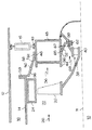
本発明の例示的な実施形態を、図1に概略的に、また図2により詳細に示している。ガスタービン又はターボファンエンジンのタービン部分10の一部は、エンジン内ケーシング14の外方に半径方向に間隔をおいて配置されたエンジン外ケーシング12を含む。環状のバイパス流路16は、エンジンの外ケーシング12と内ケーシング14との間を軸方向に延び、軸方向すなわち長手方向の中心軸線11のまわりに全て配置される。タービンブレード20は、タービン部分10内に高温の作動ガス流26を拘束するタービン流路22を横切って半径方向に延びる。タービンブレード20は、環状の先端シール24により囲まれる。本発明のガスタービンフレームを例示する後部タービンフレーム36は、後部軸受組立体38を支持し、ロータ40は、軸受組立体38に回転可能に取り付けられる。タービンブレード20は、ロータ40に駆動関係で作動的に連結される。リンク15は、後部タービンフレーム36とエンジンの内ケーシング14を、エンジンの外ケーシング12に構造的に連結する。
【0009】
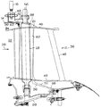
図1、図2及び図3は、本発明の第1の例示的な実施形態を示しており、ガスタービンエンジンの後部タービンフレーム36は、間をほぼ半径方向に延びる支柱48によりそれぞれ互いに接合される内側及び外側環状バンド44及び46を有する。支柱48はまた、周方向に傾斜し、すなわち傾けられているが、依然として慣習的に、半径方向に延びると言われるものである。半径方向外側の円錐形支持アーム50は、外側バンド46から半径方向外向きに延び、半径方向内側の円錐形支持アーム52は、内側バンド44から半径方向内向きに延びる。半径方向外側の円錐形支持アーム50は、環状の前部フランジ59と、外側バンド46に取り付けられた環状の外側フッタ61と、前部フランジと外側フッタとの間を延びる環状の円錐形外側シェル63とを有する。半径方向内側の円錐形支持アーム52は、環状の後部フランジ62と、内側バンド44に取り付けられた環状の内側フッタ65と、後部フランジと内側フッタとの間を延びる環状の円錐形内側シェル67とを有する。前部フランジ59は、エンジンの内ケーシング14にボルト締めされるように設計されており、環状の後部フランジ62は、軸受支持構造体69にボルト締めされるように設計されている。フレームの前部フランジ59は、フレーム36の内ケーシング14にボルト締めされ、リンク15は、外側バンド46の後部に配置され、外側バンド46をエンジン外ケーシング12に構造的に連結する。
【0010】
周方向に間隔をおいて配置される内側及び外側開口54及び56は、内側及び外側円錐形支持アーム52及び50の内側及び外側シェル67及び63にそれぞれ設けられる。支柱48の各々は、内側及び外側バンド44及び46を貫通して半径方向に延びる少なくとも1つの中空の通路60を有する。フレーム36は、単一片からなる一体の鋳造物である。内側及び外側の円錐形支持アーム52及び50は、周方向に間隔をおいて配置された等しい数の内側及び外側開口54及び56を有する。周方向に間隔をおいて配置される内側開口54は、等しい角度方向間隔で配置され、周方向に間隔をおいて配置される外側開口56は、等しい角度方向間隔で配置される。周方向に間隔をおいて配置される内側及び外側開口54及び56の各対は、対応する支柱48の1つにおける中空の通路60と直線上で整列する。本発明の他の実施形態は、内側の円錐形支持アーム52か、外側の円錐形支持アーム50のいずれか一方に、それぞれ周方向に間隔をおいて配置された内側開口54か、外側開口56のいずれかのみを備えるフレーム36を有する。
【0011】
中空の通路60は、サンプ連絡管28及び他の連絡ラインを通すために使用され、タービン部分10の設計によっては、タービン流路22と該タービン流路に存在する高温の作動ガス流26を横切って冷却空気を通すために使用される。連絡管28及び他の連絡ラインはまた、連絡ライン及び連絡管の取付けを容易にするために、外側開口56を通して配置することができる。ここには図示していないが、内側開口54を通して連絡ライン及び連絡管を配置することもできる。
【0012】
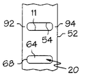
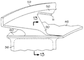
軸方向に延びるビーム90が、外側及び内側シェル63及び67の開口の間に配置され、シェルの前端96及び後端98のそれぞれの前部及び後部ヘッダー92及び94の間に延びる。ビーム90は、開口の寸法及び形状と、技術者が考慮に入れるであろう他の因子とに応じて、異なる形状及び寸法を有することができる。リンク15は、クレビス49にボルト締めされ、後部タービンフレーム36とエンジンの内ケーシング14を、エンジンの外ケーシング12に構造的に連結する。図2の例示的な実施形態では、クレビス49が、外側バンド46上に配置され、フレーム36と一体に鋳造されているところを示す。図4に示す別の実施形態では、クレビス49が、半径方向外側の円錐形支持アーム50上に配置され、フレーム36と一体に鋳造される。
【0013】
図3、図6、図7及び図9に示す本発明の第1の例示的な実施形態において、各開口は、前端68及び後端70にそれぞれ丸みのあるほぼ軸方向に細長い長方形のプラットフォーム形状64を有し、競馬場形と説明することもできる。
【0014】
図10には、外側開口56についての別の長方形の形状64を示しており、周方向に延びる幅74は、軸方向に延びる長さ76よりも大きい。環状の円錐形外側及び内側シェル63及び67は、断面が円形であり、ビーム90は、断面が長方形であり、半径方向内向き及び外向きに面する平坦面102及び104を有する。平坦なビームは、半径方向の可撓性をさらに高める。
【0015】
図8及び図11には、本発明の別の実施形態が示され、外側開口56は、隅80にフィレットが形成されたほぼ三角形のプラットフォーム形状78を有する。図11、図12、及び図13に示す別の設計では、対応する支柱48の1つにおける中空の通路60の前部97と直線上で整列するか、又はそれを覆うように配置されたビーム90を示す。
【0016】
図5には、タービン部分10が、低圧の第1及び第2ロータ40及び42をそれぞれ駆動する、低圧の前部第1及び後部タービン段18及び19を有する、本発明の別の実施形態を概略的に示す。後部タービン段19は、タービンブレード20の下流の第2ロータ42に取り付けられた後部低圧タービンブレード21を有する。低圧段の羽根43は、支柱48と低圧後部タービンブレード21との間でタービン流路22を横切るように配置される。中間軸受45は、低圧の第1ロータ40及び第2ロータ42のそれぞれの間に配置される。後部タービン段19は、フリータービンであっても良いし、出力タービンであっても良く、第2ロータ42は、リフトファン又は他の装置或いは機械を駆動するために使用される出力シャフト47を駆動するのに使用できる。
【0017】
ここでは、本発明の好ましくかつ例示的であると考えられる実施形態について説明してきたが、本発明の他の変更は、本明細書中の教示から当業者には明らかであり、したがって、本発明の技術思想及び技術的範囲に属するこれら変更の全てが、特許請求の範囲において保護される。従って、本特許出願によって保護されることを望むのは、付属の特許請求の範囲において記載している本発明である。なお、特許請求の範囲に記載された符号は、理解容易のためであってなんら発明の技術的範囲を実施例に限縮するものではない。
【図面の簡単な説明】
【図1】 本発明の例示的なタービンフレームを含む軸流ガスタービンエンジンの概略図。
【図2】 フレームの半径方向外側環状バンドとエンジン外ケーシングとの間を半径方向に延びるリンクを有する、図1に示すエンジン及びタービンフレームの一部のより詳細な断面図。
【図3】 図2に示すタービンフレームの斜視図。
【図4】 フレームの半径方向外側円錐形支持アームとエンジン外ケーシングとの間を半径方向に延びるリンクを有する、図1に示すエンジン及びタービンフレームの一部のより詳細な断面図。
【図5】 本発明のタービンフレームのタービン段後部すなわち下流部を含む別の軸流ガスタービンエンジンの概略図。
【図6】 フレームの半径方向内側の円錐形支持アームの、周方向に間隔をおいて配置された第1の例示的な内側開口の平面図。
【図7】 フレームの半径方向外側の円錐形支持アームの、周方向に間隔をおいて配置された第1の例示的な外側開口の平面図。
【図8】 フレームの半径方向外側の円錐形支持アームの、周方向に間隔をおいて配置された第2の例示的な三角形外側開口の平面図。
【図9】 フレームの半径方向外側の円錐形支持アームの、周方向に間隔をおいて配置された第1の例示的な外側開口の斜視図。
【図10】 図9に示す開口よりも幅の広い長方形のフレーム開口の間のビームに、半径方向内向き及び外向きに面する平坦な面を有する、半径方向外側の円錐形支持アームの、周方向に間隔をおいて配置された第3の例示的な外側開口の斜視図。
【図11】 図8に示す三角形の外側開口を有する、半径方向外側の円錐形支持アーム及びフレームの一部の斜視図。
【図12】 図11に示す外側円錐形支持アーム及びフレームの一部の、半径方向内向きに見た図。
【図13】 図11に示す外側円錐形支持アーム及びフレームの一部の、線13−13に沿って見た断面図。
【符号の説明】
12 外ケーシング
14 内ケーシング
15 リンク
16 バイパス流路
22 タービン流路
26 作動ガスの流れ
28 サンプ連絡管
36 タービンフレーム
38 軸受組立体
44 内側バンド
46 外側バンド
48 支柱
50 半径方向外側の円錐形支持アーム
52 半径方向内側の円錐形支持アーム
54 内側開口
56 外側開口
60 中空の通路[0001]
BACKGROUND OF THE INVENTION
The present invention relates to a gas turbine engine frame, and in particular to support of a turbine frame of a gas turbine engine by a radially outer casing.
[0002]
BACKGROUND OF THE INVENTION
Gas turbine engines, particularly aircraft gas turbine engines, support and accurately position an engine rotor in a stator by two or more structural assemblies known as frames. Each frame includes an inner ring and an outer ring connected by a number of radial struts extending between them and shaped to minimize interference with engine air flow. The outer ring is connected to the inner casing of the engine by a radially outer conical support arm, and the support of the radially inner conical support arm is used to support the bearing assembly. The support portion of the radially inner conical support arm is typically connected and used to support the sump of the bearing assembly. In some engine designs, the inner casing is attached by a link within and to the outer engine casing. In many cases, a hollow passage is provided in the strut, through which a communication line such as a sump connection pipe is passed, and sometimes across the hot working gas in the turbine flow path, inside and Cooling air flows between the outer ring and the radial struts.
[0003]
The radially outer and inner conical support arms are continuous hoop members that are exposed to high temperatures, transmit loads, and undergo hoop stress. Hoop stress is caused by large operating temperature differences between the frame and the bearing and between the frame and the inner casing. For conical support arms radially outside and inside the frame and turbine assembly, it is desirable to have a design that reduces or eliminates these hoop stresses in the support arms.
[0004]
SUMMARY OF THE INVENTION
In the exemplary embodiment of the invention shown here, the gas turbine frame has inner and outer annular bands that are joined together by struts extending generally radially therebetween. A radially outer conical support arm extends radially outward from the outer band, and a radially inner conical support arm extends radially inward from the inner band. Inner and outer openings are provided in the inner and outer conical support arms, respectively, spaced circumferentially. Each of the struts has at least one hollow passage extending radially through the inner and outer bands. The frame is a unitary casting made of a single piece. The inner and outer conical support arms have an equal number of inner and outer openings spaced circumferentially apart. Inner openings arranged at intervals in the circumferential direction are arranged at equal angular intervals, and outer openings arranged at intervals in the circumferential direction are arranged at equal angular intervals. Each pair of inner and outer openings spaced circumferentially is aligned in line with one hollow passage of the corresponding strut.
[0005]
In a particular one of the embodiments of the present invention, each opening has a generally rectangular platform shape with rounded front and back ends, and in another embodiment, each opening has a fillet formed in the corner. It has a substantially triangular platform shape.
[0006]
The frame of the present invention provides the structural coupling between the relatively cool engine casing and the inner sump of the bearing that traverses the relatively hot flow path, while avoiding the thermal hoop stress that has occurred in conventional designs. Avoid destructive levels. The present invention can also improve the castability of the single piece cast frame of the present invention by providing an opening in a narrow cavity between the band and the support arm. This feature facilitates manufacturing by investment casting. The present invention also improves castability by providing heat flexibility and reducing the tendency for hot cracks to occur during the solidification of the cast alloy. The cutout or opening also allows access to the strut end for inserting the sump connecting tube.
[0007]
DETAILED DESCRIPTION OF THE INVENTION
Aspects and features of the present invention are described in the following detailed description with reference to the accompanying drawings.
[0008]
An exemplary embodiment of the invention is shown schematically in FIG. 1 and in more detail in FIG. A portion of the
[0009]
FIGS. 1, 2 and 3 show a first exemplary embodiment of the present invention in which the
[0010]
Circumferentially spaced inner and
[0011]
The
[0012]
An axially extending
[0013]
In the first exemplary embodiment of the present invention shown in FIGS. 3, 6, 7 and 9, each opening has a generally axially elongated rectangular platform shape with rounded front and
[0014]
FIG. 10 shows another
[0015]
8 and 11 illustrate another embodiment of the present invention, wherein the
[0016]
FIG. 5 shows another embodiment of the invention in which the
[0017]
Although preferred and illustrative embodiments of the invention have been described herein, other modifications of the invention will be apparent to those skilled in the art from the teachings herein, and thus the invention All of these modifications within the technical concept and scope of this invention are protected by the following claims. Accordingly, what is desired to be secured by Letters Patent application is the invention as set forth in the appended claims. In addition, the code | symbol described in the claim is for easy understanding, and does not limit the technical scope of an invention to an Example at all.
[Brief description of the drawings]
FIG. 1 is a schematic diagram of an axial gas turbine engine including an exemplary turbine frame of the present invention.
2 is a more detailed cross-sectional view of a portion of the engine and turbine frame shown in FIG. 1 having a link extending radially between the radially outer annular band of the frame and the engine outer casing.
3 is a perspective view of the turbine frame shown in FIG. 2. FIG.
4 is a more detailed cross-sectional view of a portion of the engine and turbine frame shown in FIG. 1 having a link extending radially between the radially outer conical support arm of the frame and the outer casing of the engine.
FIG. 5 is a schematic view of another axial gas turbine engine including the turbine stage rear or downstream portion of the turbine frame of the present invention.
FIG. 6 is a plan view of a first exemplary inner opening, spaced circumferentially, of a conical support arm radially inward of the frame.
FIG. 7 is a plan view of a first exemplary outer opening spaced circumferentially of a conical support arm radially outward of the frame.
FIG. 8 is a plan view of a second exemplary triangular outer opening spaced circumferentially of a conical support arm radially outward of the frame.
FIG. 9 is a perspective view of a first exemplary outer opening spaced circumferentially of a conical support arm radially outward of the frame.
10 shows a radially outer conical support arm having a flat surface facing radially inward and outward in a beam between rectangular frame openings wider than the opening shown in FIG. 9; FIG. 6 is a perspective view of a third exemplary outer opening spaced circumferentially apart.
FIG. 11 is a perspective view of a portion of the radially outer conical support arm and frame with the triangular outer opening shown in FIG. 8;
12 is a radially inward view of a portion of the outer conical support arm and frame shown in FIG. 11;
13 is a cross-sectional view of the portion of the outer conical support arm and frame shown in FIG. 11, taken along line 13-13.
[Explanation of symbols]
12
Claims (12)
前記外側バンド(46)から半径方向外向きに延びる半径方向外側の円錐形支持アーム(50)と、
前記内側バンド(44)から半径方向内向きに延びる半径方向内側の円錐形支持アーム(52)と、
前記内側及び外側円錐形支持アーム(52及び50)に周方向に間隔をおいて形成された内側及び外側開口(54及び56)と、
を含むことを特徴とするガスタービンフレーム(36)。Radially inner and outer annular bands (44 and 46) joined together by struts (48) extending radially therebetween,
A radially outer conical support arm (50) extending radially outward from the outer band (46);
A radially inner conical support arm (52) extending radially inward from the inner band (44);
Inner and outer openings (54 and 56) circumferentially spaced in the inner and outer conical support arms (52 and 50);
A gas turbine frame (36) characterized by comprising:
前記外側バンド(46)から半径方向外向きに延びる半径方向外側の円錐形支持アーム(50)と、
周方向に間隔をおいて前記半径方向外側円錐形支持アーム(50)に形成された外側開口(56)と、
を含むことを特徴とするガスタービンフレーム(36)。Radially inner and outer annular bands (44 and 46) joined together by struts (48) extending radially therebetween,
A radially outer conical support arm (50) extending radially outward from the outer band (46);
An outer opening (56) formed in the radially outer conical support arm (50) at circumferentially spaced intervals;
A gas turbine frame (36) characterized by comprising:
前記内側バンド(44)から半径方向内向きに延びる半径方向内側の円錐形支持アーム(52)と、
前記半径方向内側円錐形支持アーム(52)に周方向に間隔をおいて形成された内側開口(54)と、
を含み、各開口が、前端及び後端(68及び70)に丸みのあるほぼ長方形のプラットフォーム形状(64)を有することを特徴とするガスタービンフレーム(36)。 A radially inner and outer ring-shaped bands (44 and 46) which are joined together by struts (48) extending radially between,
A radially inner conical support arm (52) extending radially inward from the inner band (44);
An inner opening (54) formed circumferentially spaced in the radially inner conical support arm (52);
A gas turbine frame (36) wherein each opening has a generally rectangular platform shape (64) with rounded front and rear ends (68 and 70).
前記内側バンド(44)から半径方向内向きに延びる半径方向内側の円錐形支持アーム(52)と、
前記半径方向内側円錐形支持アーム(52)に周方向に間隔をおいて形成された内側開口(54)と、
を含み、各開口が、隅(80)にフィレットが形成されたほぼ三角形のプラットフォーム形状(78)を有することを特徴とするガスタービンフレーム(36)。 Radially inner and outer annular bands (44 and 46) joined together by struts (48) extending radially therebetween,
A radially inner conical support arm (52) extending radially inward from the inner band (44);
An inner opening (54) formed circumferentially spaced in the radially inner conical support arm (52);
A gas turbine frame (36) wherein each opening has a generally triangular platform shape (78) with a fillet formed in a corner (80).
該ガスタービンフレーム(36)が内側でかつそれに取付けられたタービン外ケーシング(12)と、
前記半径方向内側の円錐形支持アーム(52)の内側に取付けられた軸受組立体(38)と、
を含むことを特徴とするガスタービン組立体。A gas turbine frame (36) according to any one of the preceding claims ,
An outer turbine casing (12) with the gas turbine frame (36) inside and attached thereto;
A bearing assembly (38) mounted inside the radially inner conical support arm (52);
A gas turbine assembly comprising:
Applications Claiming Priority (2)
| Application Number | Priority Date | Filing Date | Title |
|---|---|---|---|
| US09/827,850 US6547518B1 (en) | 2001-04-06 | 2001-04-06 | Low hoop stress turbine frame support |
| US09/827850 | 2001-04-06 |
Publications (3)
| Publication Number | Publication Date |
|---|---|
| JP2002317604A JP2002317604A (en) | 2002-10-31 |
| JP2002317604A5 JP2002317604A5 (en) | 2005-08-11 |
| JP4137486B2 true JP4137486B2 (en) | 2008-08-20 |
Family
ID=25250324
Family Applications (1)
| Application Number | Title | Priority Date | Filing Date |
|---|---|---|---|
| JP2002101965A Expired - Fee Related JP4137486B2 (en) | 2001-04-06 | 2002-04-04 | Turbine frame and turbine assembly |
Country Status (3)
| Country | Link |
|---|---|
| US (1) | US6547518B1 (en) |
| EP (1) | EP1247944B1 (en) |
| JP (1) | JP4137486B2 (en) |
Families Citing this family (56)
| Publication number | Priority date | Publication date | Assignee | Title |
|---|---|---|---|---|
| GB2402717B (en) * | 2003-06-10 | 2006-05-10 | Rolls Royce Plc | A vane assembly for a gas turbine engine |
| FR2860041B1 (en) * | 2003-09-22 | 2005-11-25 | Snecma Moteurs | REALIZING THE SEALING IN A TURBOJET FOR THE DOUBLE BALL TUBE COLLECTION |
| US7757768B2 (en) * | 2004-10-08 | 2010-07-20 | Halliburton Energy Services, Inc. | Method and composition for enhancing coverage and displacement of treatment fluids into subterranean formations |
| SE528948C2 (en) * | 2004-12-23 | 2007-03-20 | Volvo Aero Corp | Annular torque static component for an aircraft engine |
| SE528006C2 (en) * | 2004-12-23 | 2006-08-01 | Volvo Aero Corp | Static gas turbine component and method of repairing such component |
| EP1647576A1 (en) * | 2005-04-01 | 2006-04-19 | Huntsman Advanced Materials (Switzerland) GmbH | Composition comprising benzoxazine and epoxy resin |
| FR2891301B1 (en) * | 2005-09-29 | 2007-11-02 | Snecma Sa | STRUCTURAL CASING OF TURBOMOTEUR |
| US7914255B2 (en) * | 2006-04-21 | 2011-03-29 | General Electric Company | Apparatus and method of diaphragm assembly |
| US7730715B2 (en) * | 2006-05-15 | 2010-06-08 | United Technologies Corporation | Fan frame |
| US20100303608A1 (en) * | 2006-09-28 | 2010-12-02 | Mitsubishi Heavy Industries, Ltd. | Two-shaft gas turbine |
| US8726675B2 (en) * | 2007-09-07 | 2014-05-20 | The Boeing Company | Scalloped flexure ring |
| FR2933130B1 (en) * | 2008-06-25 | 2012-02-24 | Snecma | STRUCTURAL CASING FOR TURBOMACHINE |
| GB0904970D0 (en) | 2009-03-24 | 2009-05-06 | Rolls Royce Plc | A casing arrangement |
| US8313293B2 (en) * | 2009-05-15 | 2012-11-20 | Pratt & Whitney Canada Corp. | Turbofan mounting system |
| US8567202B2 (en) | 2009-05-15 | 2013-10-29 | Pratt & Whitney Canada Corp. | Support links with lockable adjustment feature |
| US8979491B2 (en) | 2009-05-15 | 2015-03-17 | Pratt & Whitney Canada Corp. | Turbofan mounting arrangement |
| US8511089B2 (en) * | 2009-07-31 | 2013-08-20 | Rolls-Royce Corporation | Relief slot for combustion liner |
| US9284887B2 (en) | 2009-12-31 | 2016-03-15 | Rolls-Royce North American Technologies, Inc. | Gas turbine engine and frame |
| US8753075B2 (en) * | 2010-07-20 | 2014-06-17 | Rolls-Royce Corporation | Fan case assembly and method |
| FR2975131B1 (en) * | 2011-05-09 | 2015-12-25 | Snecma | SUSPENSION OF THE COLD FLOW CHANNEL OF A TURBOJET ENGINE BY CONNECTING RODS AND RADIAL CHAPELS ON THE EXHAUST CASING |
| US8944753B2 (en) | 2011-11-09 | 2015-02-03 | Pratt & Whitney Canada Corp. | Strut mounting arrangement for gas turbine exhaust case |
| US8826669B2 (en) | 2011-11-09 | 2014-09-09 | Pratt & Whitney Canada Corp. | Gas turbine exhaust case |
| US9200537B2 (en) | 2011-11-09 | 2015-12-01 | Pratt & Whitney Canada Corp. | Gas turbine exhaust case with acoustic panels |
| EP2788585B1 (en) | 2011-12-08 | 2018-11-21 | GKN Aerospace Sweden AB | Gas turbine engine component |
| WO2013095202A1 (en) * | 2011-12-20 | 2013-06-27 | Volvo Aero Corporation | Method for manufacturing of a gas turbine engine component |
| US9689312B2 (en) | 2011-12-22 | 2017-06-27 | Gkn Aerospace Sweden Ab | Gas turbine engine component |
| US10012108B2 (en) | 2011-12-23 | 2018-07-03 | Gkn Aerospace Sweden Ab | Gas turbine engine component |
| JP5946543B2 (en) | 2011-12-23 | 2016-07-06 | ゲーコーエヌ エアロスペース スウェーデン アーベー | Gas turbine engine support structure |
| US9316117B2 (en) | 2012-01-30 | 2016-04-19 | United Technologies Corporation | Internally cooled spoke |
| US9140137B2 (en) | 2012-01-31 | 2015-09-22 | United Technologies Corporation | Gas turbine engine mid turbine frame bearing support |
| US9194296B2 (en) | 2012-05-18 | 2015-11-24 | Pratt & Whitney Canada Corp. | Inner bypass duct wall attachment |
| US9091173B2 (en) | 2012-05-31 | 2015-07-28 | United Technologies Corporation | Turbine coolant supply system |
| FR2994712B1 (en) * | 2012-08-27 | 2018-04-13 | Safran Aircraft Engines | METHOD FOR ASSEMBLING A TUBE AND AN EXHAUST HOUSING OF A TURBOMACHINE |
| FR2995344B1 (en) * | 2012-09-10 | 2014-09-26 | Snecma | METHOD FOR MANUFACTURING AN EXHAUST CASE OF COMPOSITE MATERIAL FOR A GAS TURBINE ENGINE AND AN EXHAUST CASE THUS OBTAINED |
| US11300003B2 (en) | 2012-10-23 | 2022-04-12 | General Electric Company | Unducted thrust producing system |
| EP2912270B1 (en) | 2012-10-23 | 2023-04-26 | General Electric Company | Unducted thrust producing system |
| US20150322815A1 (en) * | 2012-12-29 | 2015-11-12 | Pw Power Systems, Inc. | Cast steel frame for gas turbine engine |
| US9631517B2 (en) | 2012-12-29 | 2017-04-25 | United Technologies Corporation | Multi-piece fairing for monolithic turbine exhaust case |
| EP3011139B1 (en) * | 2013-06-17 | 2021-03-31 | Raytheon Technologies Corporation | Unitary one piece gas turbine hub |
| US9598981B2 (en) * | 2013-11-22 | 2017-03-21 | Siemens Energy, Inc. | Industrial gas turbine exhaust system diffuser inlet lip |
| US10072746B2 (en) * | 2015-05-05 | 2018-09-11 | Valeo Embrayages | Stator assembly of hydrokinetic torque converter, and method for making the same |
| CN104948301A (en) * | 2015-05-20 | 2015-09-30 | 西安交通大学 | Hot end bearing of gas turbine |
| US10247035B2 (en) | 2015-07-24 | 2019-04-02 | Pratt & Whitney Canada Corp. | Spoke locking architecture |
| WO2017015746A1 (en) | 2015-07-24 | 2017-02-02 | Pratt & Whitney Canada Corp. | Mid-turbine frame spoke cooling system and method |
| US10443449B2 (en) | 2015-07-24 | 2019-10-15 | Pratt & Whitney Canada Corp. | Spoke mounting arrangement |
| US11391298B2 (en) | 2015-10-07 | 2022-07-19 | General Electric Company | Engine having variable pitch outlet guide vanes |
| DE102016201581A1 (en) * | 2016-02-02 | 2017-08-03 | MTU Aero Engines AG | Rotor-stator composite for an axial flow machine and aircraft engine |
| US10113483B2 (en) * | 2016-02-23 | 2018-10-30 | General Electric Company | Sump housing for a gas turbine engine |
| US11174786B2 (en) | 2016-11-15 | 2021-11-16 | General Electric Company | Monolithic superstructure for load path optimization |
| US10837320B2 (en) | 2018-09-25 | 2020-11-17 | Honeywell International Inc. | Frangible strut for gas turbine engine |
| CN113356946B (en) * | 2021-07-22 | 2022-08-19 | 中国航发沈阳发动机研究所 | Interturbine casing structure of aircraft engine |
| US11492918B1 (en) | 2021-09-03 | 2022-11-08 | General Electric Company | Gas turbine engine with third stream |
| US11834995B2 (en) | 2022-03-29 | 2023-12-05 | General Electric Company | Air-to-air heat exchanger potential in gas turbine engines |
| US11834954B2 (en) | 2022-04-11 | 2023-12-05 | General Electric Company | Gas turbine engine with third stream |
| US11834992B2 (en) | 2022-04-27 | 2023-12-05 | General Electric Company | Heat exchanger capacity for one or more heat exchangers associated with an accessory gearbox of a turbofan engine |
| US11680530B1 (en) | 2022-04-27 | 2023-06-20 | General Electric Company | Heat exchanger capacity for one or more heat exchangers associated with a power gearbox of a turbofan engine |
Family Cites Families (12)
| Publication number | Priority date | Publication date | Assignee | Title |
|---|---|---|---|---|
| GB926947A (en) * | 1961-11-27 | 1963-05-22 | Rolls Royce | Improvements relating to gas turbine engine casings |
| US4571936A (en) | 1985-07-10 | 1986-02-25 | The United States Of America As Represented By The Secretary Of The Air Force | Length adjustable strut link with low aerodynamic drag |
| US4907946A (en) | 1988-08-10 | 1990-03-13 | General Electric Company | Resiliently mounted outlet guide vane |
| US4987736A (en) * | 1988-12-14 | 1991-01-29 | General Electric Company | Lightweight gas turbine engine frame with free-floating heat shield |
| US4989406A (en) | 1988-12-29 | 1991-02-05 | General Electric Company | Turbine engine assembly with aft mounted outlet guide vanes |
| US5160251A (en) * | 1991-05-13 | 1992-11-03 | General Electric Company | Lightweight engine turbine bearing support assembly for withstanding radial and axial loads |
| US5165850A (en) | 1991-07-15 | 1992-11-24 | General Electric Company | Compressor discharge flowpath |
| US5249921A (en) | 1991-12-23 | 1993-10-05 | General Electric Company | Compressor outlet guide vane support |
| US5272869A (en) | 1992-12-10 | 1993-12-28 | General Electric Company | Turbine frame |
| DE19615011A1 (en) * | 1995-07-19 | 1997-01-23 | Siemens Ag | Component for an exhaust pipe of a turbomachine, in particular a steam turbine |
| US5597286A (en) | 1995-12-21 | 1997-01-28 | General Electric Company | Turbine frame static seal |
| US5634767A (en) | 1996-03-29 | 1997-06-03 | General Electric Company | Turbine frame having spindle mounted liner |
-
2001
- 2001-04-06 US US09/827,850 patent/US6547518B1/en not_active Expired - Lifetime
-
2002
- 2002-04-04 JP JP2002101965A patent/JP4137486B2/en not_active Expired - Fee Related
- 2002-04-05 EP EP02252453A patent/EP1247944B1/en not_active Expired - Fee Related
Also Published As
| Publication number | Publication date |
|---|---|
| EP1247944A2 (en) | 2002-10-09 |
| US20030077166A1 (en) | 2003-04-24 |
| US6547518B1 (en) | 2003-04-15 |
| EP1247944B1 (en) | 2012-12-05 |
| EP1247944A3 (en) | 2009-04-08 |
| JP2002317604A (en) | 2002-10-31 |
Similar Documents
| Publication | Publication Date | Title |
|---|---|---|
| JP4137486B2 (en) | Turbine frame and turbine assembly | |
| JP5525119B2 (en) | Turbine assembly and turbine shroud thereof | |
| CA2513079C (en) | Lightweight annular interturbine duct | |
| CA2715596C (en) | Fabricated static vane ring | |
| US10370986B2 (en) | Nozzle and nozzle assembly for gas turbine engine | |
| JP4513000B2 (en) | Method and apparatus for assembling a gas turbine engine | |
| JP4856302B2 (en) | Compressor blisk flow path with reduced stress | |
| US5248240A (en) | Turbine stator vane assembly | |
| US20170016341A1 (en) | Shroud assembly for gas turbine engine | |
| JP2017040262A (en) | Cmc nozzles with split endwalls for gas turbine engines | |
| US10132197B2 (en) | Shroud assembly and shroud for gas turbine engine | |
| CA2935369A1 (en) | Method and system for interfacing a ceramic matrix composite component to a metallic component | |
| EP3101233B1 (en) | Methods for positioning neighboring nozzles of a gas turbine engine | |
| JP4402196B2 (en) | Low distortion shroud for turbines | |
| CA2728701A1 (en) | A structural frame for a turbomachine | |
| JP2016194297A (en) | Turbine frame and airfoil for turbine frame | |
| JP2016205390A5 (en) | ||
| US20090110548A1 (en) | Abradable rim seal for low pressure turbine stage | |
| EP3147459A2 (en) | Nozzle and nozzle assembly for gas turbine engine | |
| JP2008196327A (en) | Turbocharger |
Legal Events
| Date | Code | Title | Description |
|---|---|---|---|
| A521 | Written amendment |
Free format text: JAPANESE INTERMEDIATE CODE: A523 Effective date: 20050126 |
|
| A621 | Written request for application examination |
Free format text: JAPANESE INTERMEDIATE CODE: A621 Effective date: 20050126 |
|
| A131 | Notification of reasons for refusal |
Free format text: JAPANESE INTERMEDIATE CODE: A131 Effective date: 20070904 |
|
| A521 | Written amendment |
Free format text: JAPANESE INTERMEDIATE CODE: A523 Effective date: 20071203 |
|
| TRDD | Decision of grant or rejection written | ||
| A01 | Written decision to grant a patent or to grant a registration (utility model) |
Free format text: JAPANESE INTERMEDIATE CODE: A01 Effective date: 20080507 |
|
| A01 | Written decision to grant a patent or to grant a registration (utility model) |
Free format text: JAPANESE INTERMEDIATE CODE: A01 |
|
| A61 | First payment of annual fees (during grant procedure) |
Free format text: JAPANESE INTERMEDIATE CODE: A61 Effective date: 20080604 |
|
| R150 | Certificate of patent or registration of utility model |
Free format text: JAPANESE INTERMEDIATE CODE: R150 |
|
| FPAY | Renewal fee payment (event date is renewal date of database) |
Free format text: PAYMENT UNTIL: 20110613 Year of fee payment: 3 |
|
| FPAY | Renewal fee payment (event date is renewal date of database) |
Free format text: PAYMENT UNTIL: 20120613 Year of fee payment: 4 |
|
| FPAY | Renewal fee payment (event date is renewal date of database) |
Free format text: PAYMENT UNTIL: 20120613 Year of fee payment: 4 |
|
| FPAY | Renewal fee payment (event date is renewal date of database) |
Free format text: PAYMENT UNTIL: 20130613 Year of fee payment: 5 |
|
| R250 | Receipt of annual fees |
Free format text: JAPANESE INTERMEDIATE CODE: R250 |
|
| R250 | Receipt of annual fees |
Free format text: JAPANESE INTERMEDIATE CODE: R250 |
|
| R250 | Receipt of annual fees |
Free format text: JAPANESE INTERMEDIATE CODE: R250 |
|
| R250 | Receipt of annual fees |
Free format text: JAPANESE INTERMEDIATE CODE: R250 |
|
| LAPS | Cancellation because of no payment of annual fees |