JP4136751B2 - Whetstone with shaft - Google Patents
Whetstone with shaft Download PDFInfo
- Publication number
- JP4136751B2 JP4136751B2 JP2003089079A JP2003089079A JP4136751B2 JP 4136751 B2 JP4136751 B2 JP 4136751B2 JP 2003089079 A JP2003089079 A JP 2003089079A JP 2003089079 A JP2003089079 A JP 2003089079A JP 4136751 B2 JP4136751 B2 JP 4136751B2
- Authority
- JP
- Japan
- Prior art keywords
- grindstone
- abrasive
- notch
- shaft
- inclined surface
- Prior art date
- Legal status (The legal status is an assumption and is not a legal conclusion. Google has not performed a legal analysis and makes no representation as to the accuracy of the status listed.)
- Expired - Fee Related
Links
- 239000000463 material Substances 0.000 claims description 67
- 230000002093 peripheral effect Effects 0.000 claims description 24
- 239000006061 abrasive grain Substances 0.000 claims description 22
- 238000005553 drilling Methods 0.000 claims description 21
- 239000003082 abrasive agent Substances 0.000 claims description 13
- 230000000694 effects Effects 0.000 description 10
- 238000010586 diagram Methods 0.000 description 6
- 239000000919 ceramic Substances 0.000 description 4
- 239000011521 glass Substances 0.000 description 4
- 238000005336 cracking Methods 0.000 description 3
- 230000007423 decrease Effects 0.000 description 3
- 238000007599 discharging Methods 0.000 description 3
- 230000004323 axial length Effects 0.000 description 2
- 239000012530 fluid Substances 0.000 description 2
- 230000014759 maintenance of location Effects 0.000 description 2
- 238000003466 welding Methods 0.000 description 2
- PNEYBMLMFCGWSK-UHFFFAOYSA-N Alumina Chemical compound [O-2].[O-2].[O-2].[Al+3].[Al+3] PNEYBMLMFCGWSK-UHFFFAOYSA-N 0.000 description 1
- 230000015572 biosynthetic process Effects 0.000 description 1
- 229910003460 diamond Inorganic materials 0.000 description 1
- 239000010432 diamond Substances 0.000 description 1
- 238000004519 manufacturing process Methods 0.000 description 1
- 238000003672 processing method Methods 0.000 description 1
- 239000004575 stone Substances 0.000 description 1
Images


Landscapes
- Polishing Bodies And Polishing Tools (AREA)
Description
【0001】
【発明の属する技術分野】
本発明は、セラミックやガラス等の穴あけ加工等に用いられる軸付き砥石(コアドリル)に関する。
【0002】
【従来の技術】
セラミックやガラス等の穴あけ加工用として、軸部と砥材層とからなる軸付き砥石が用いられている。セラミックやガラスは、その硬くて脆い性質のために、加工に用いられる砥石の寿命が短く、被削材にチッピングやクラックが発生しやすい。
砥石寿命や砥石の強度は、軸付き砥石の先端形状によって影響を受ける。特に、穴あけ加工の初期において、被削材に接触する砥石の面積の大きさによって、砥石の寿命が大きく左右される傾向がある。
【0003】
被削材に接触する砥石の面積が大きいと、接触抵抗が大きくなり、被削材の溶着、目詰まりが多くなり、砥石寿命が低下する。その逆に、被削材に接触する砥石の面積が小さいと、被削材に作用する砥粒数が少なすぎたり、砥石強度が不足するなどして、砥石を十分に使いきることなく破損してしまう。
【0004】
また、チッピングやクラックの発生は、軸付き砥石を用いて、セラミックやガラスのように硬くて脆い被削材に対して貫通穴を開ける際に起こりやすい。砥石が被削材を抜け出る面ではチッピングが大きくなるため、初めに被削材の幅の中間の位置まで穴あけし、その後反転して逆側の面から穴あけすることによって、チッピングを小さくしている。
【0005】
【発明が解決しようとする課題】
しかし、このような加工方法では、作業性が悪いばかりでなく、チッピングの発生防止も十分ではない。
本発明は、このような事情を考慮してなされたもので、効率良く切粉を排出して切味と砥石寿命を向上するとともに、チッピングの発生を抑制して、良好な加工面が得られる軸付き砥石を提供することを目的とする。
【0006】
【課題を解決するための手段】
以上の課題を解決するために、本発明は、軸部の先端に砥材層が形成され、砥材層は砥粒をボンド材により固着して形成されている穴あけ加工用軸付き砥石において、前記砥材層の外周側に開口した扇状の切欠部が複数設けられ、前記切欠部の軸は砥材層の軸と一致するように形成され、前記切欠部は互いにその扇状の開口角度の大きさが異なることを特徴とする軸付き砥石である。
切欠部を扇形とすることによって、効率良く切粉を排出することができ、切味と砥石寿命が向上する。
切欠部の扇状の開口角度の大きさが互いに異なるようにすることによって、砥石の外周面と被削材との接触による接触抵抗に差を生じ、それぞれの切欠部が設けられた位置において、切味の差が生じる。この切味の差によって、砥石の回転時に強制的な振れが生じ、これによって砥石と被削材との間に隙間ができ、この隙間によって切粉の排出性が高まり、研削効率を向上させることができる。
【0007】
本発明の軸付き砥石においては、前記切欠部の扇状の開口角度が15°以上90°以下であることを特徴とする。
切欠部の扇状の開口角度が15°未満であると、開口角度が狭くなりすぎて切粉の排出効果が得にくくなって目詰まりを起こしやすい。一方、切欠部の扇状の開口角度が90°を超えると、研削時に切欠部による研削抵抗が大きくなるとともに、砥材層の体積が減少するため、十分な強度が得られなくなる。そのため、切欠部の扇状の開口角度は15°以上90°以下であることが好ましい。
【0008】
本発明の軸付き砥石においては、前記切欠部のうち開口角度が最大の切欠部によって形成される断面の断面積または切欠部の体積に対して、その他の切欠部によって形成される断面の断面積または切欠部の体積が80%以下であることを特徴とする
切欠部の大きさの差が上記の範囲外であると、切欠部の大きさの差による研削抵抗の差が小さすぎて、切欠部を異なる大きさとしたことによる効果が得られにくいためである。
【0009】
本発明の軸付き砥石においては、前記切欠部の軸方向の長さは、前記砥材層の軸方向の長さの50%以上100%以下であることを特徴とする。
切欠部の軸方向の長さが上記の範囲外であると、切粉の排出と研削液の供給を十分に行うことができないからである。
【0010】
本発明の軸付き砥石においては、前記砥材層の先端部に平坦部が形成されていることを特徴とする。
砥材層の先端部に平坦部を形成することにより、穴あけ加工の初期において砥石の点当たりを防止することができ、作用する砥粒数を増やして1砥粒当たりの負荷を軽減することができる。
この平坦部の面積は、穴あけ面積の20%以上80%以下であることが好ましい。20%未満であると平坦部を形成したことによる上記の効果が得られにくく、80%を超えると被削材との接触抵抗が過多となり、被削材の溶着、目詰まりによって切味が低下する。
【0011】
本発明の軸付き砥石においては、前記砥材層の外周側側面に傾斜面が形成されていることを特徴とする。
砥材層の外周側側面に傾斜面を形成したことにより、砥石が被削材から抜け出る際の被削材への負担を軽減することができ、この際の穴外周部でのチッピングやクラックの発生を防止することができる。
【0012】
この傾斜面は、前記平坦部に対して40°以上60°以下の傾斜角をなして形成されていることが好ましい。40°未満であると、穴が被削材中を貫通する際に、被削材に対して傾斜面に垂直な方向に作用する力が大きくなり、この力によって、砥石が被削材を抜け出る際に被削材を破損しやすい。その一方、60°を超えると、被削材に対して傾斜面に沿う方向に作用する力が大きくなり、この力によって、砥石が被削材を抜け出る際に被削材を破損しやすい。従って、傾斜面の傾斜角が平坦部に対して40°以上60°以下であるときに、被削材に対して傾斜面に沿う方向に作用する力と、被削材に対して傾斜面に沿う方向に作用する力とのバランスをとることができ、穴外周部でのチッピングやクラックの発生を防止しやすい。
【0013】
本発明の軸付き砥石においては、前記平坦部と前記傾斜面との接続部、および前記傾斜面と砥材層外周側面との接続部はいずれもR形状であることを特徴とする。
前記平坦部と前記傾斜面との接続部の曲率は砥粒粒径の3倍以上とすることが好ましく、前記傾斜面と砥材層外周側面との接続部の曲率は穴あけ半径の30%以上100%以下とすることが好ましい。
【0014】
前記平坦部と前記傾斜面との接続部の曲率が砥粒粒径の3倍未満であると、砥材層のコーナーにおける負荷に対する砥粒保持力が低下してしまう。この曲率を砥粒粒径の3倍以上とすることによって、砥粒保持力を維持することができ、穴あけ加工初期における砥粒の脱落によるコーナーだれを軽減して寿命を向上することができる。
また、前記傾斜面と砥材層外周側面との接続部の曲率を穴あけ半径の30%以上100%以下とすることによって、被削材に対する研削負荷を分散させることができ、砥石が被削材から抜け出る側の穴外周部のチッピングやクラックの発生を防止することができる。
【0015】
【発明の実施の形態】
以下、本発明の軸付き砥石をその実施の形態に基づいて説明する。
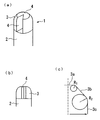
図1に、本発明の実施の形態に係る軸付き砥石を示す。図1(a)は軸付き砥石の斜視図であり、同図(b)は軸付き砥石の正面図である。また、同図(c)は軸付き砥石の部分拡大図である。
図1に示すように、軸付き砥石1は軸部2の先端に砥材層3を形成してなるものであり、砥材層3はダイヤモンド等からなる砥粒をボンド材により固着して形成されている。砥材層3の外周側に開口した扇状の切欠部4が複数設けられ、切欠部4は互いにその大きさが異なっている。
【0016】
砥材層3は図1(d)に示すように、砥材層3の先端部に平坦部3aが形成され、外周側側面に傾斜面3bが形成されている。平坦部3aと傾斜面3bとの接続部、および傾斜面3bと砥材層外周側面3cとの接続部はいずれもR形状となっている。
【0017】
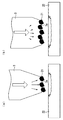
図2に、大きさが等しい2つの切欠部を設けたときと、大きさが異なる2つの切欠部を設けたときについて、研削時における被削材との接触による接触抵抗と、切粉の排出の様子を示す。図2において、曲線状の矢印は砥石の回転方向を示す。また、直線状の矢印は、切欠部における被削材との接触による接触抵抗の大きさと方向を示す。
図2(a)に、大きさが等しい2つの切欠部を設けた砥石を示し、図2(b)に、大きさが異なる2つの切欠部を設けた砥石を示す。
図2(a)では、切欠部の大きさが等しいために、研削時における被削材との接触による接触抵抗は、いずれの切欠部においても等しい。
【0018】
これに対し、図2(b)では、切欠部の大きさが異なるために、被削材との接触による接触抵抗は、大きい切欠部において大きくなる。その結果、それぞれの切欠部が設けられた位置において、切味の差が生じる。この切味の差によって、砥石の回転時に強制的な振れが生じ、これによって砥石と被削材との間に隙間11ができ、この隙間11によって切粉の排出性が高まり、研削効率を向上させることができる。
【0019】
大きさが等しい2つの切欠部を設けた砥石では、図2(a)に示すように、砥石と被削材との間に隙間11を生じないため、切粉12は切欠部によってのみ排出される。これに対し、大きさが異なる2つの切欠部を設けた砥石では、砥石と被削材との間に隙間11を生じるため、切粉12は切欠部ばかりでなく隙間11からも排出され、排出効率が高まる。
【0020】
図3は、砥材層の先端部に形成された平坦部の面積を変えたときに、被削材22に作用する力を示したものである。
砥材層3の先端部に平坦部3aを形成することにより、穴あけ加工の初期において砥石の点当たりを防止することができ、作用する砥粒数を増やして1砥粒当たりの負荷を軽減することができる。
【0021】
しかし、平坦部3aの面積が狭すぎると、図3(a)に示すように、各砥粒21にかかる負荷が大きくなって平坦部3aを設けた効果が得られにくい。
平坦部3aの面積が、穴あけ面積の20%以上80%以下であると、図3(b)に示すように、各砥粒21にかかる負荷が分散され、作用する砥粒数を増やして1砥粒当たりの負荷を軽減することが可能となる。
ただし、平坦部3aの面積が穴あけ面積の80%を超えると、被削材22との接触抵抗が過多となり、被削材の溶着、目詰まりによって切味が低下する。
【0022】
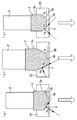
図4は、砥材層の外周側側面に傾斜面を形成し、傾斜面の傾斜角を変えたときに、被削材に対して作用する力の変化を示したものである。図4において、白抜きの矢印が、穴あけの方向を示し、黒い矢印が被削材に対して作用する力を示す。
図4(a)は、傾斜角を平坦部3aに対して40°未満とした場合であり、図4(b)は、傾斜角を平坦部3aに対して60°を超える値とした場合であり、図4(c)は、傾斜角を平坦部3aに対して40°以上60°以下とした場合である。
【0023】
図4(a)に示すように、傾斜角が40°未満であると、穴が被削材22中を貫通する際に、被削材22に対して、傾斜面3bに垂直な方向に作用する力faが大きくなり、この力によって、砥石が被削材22を抜け出る際に被削材22を破損しやすい。
図4(b)に示すように、傾斜角が60°を超えると、被削材22に対して、傾斜面3bに沿う方向に作用する力fbが大きくなり、この力によって、砥石が被削材22を抜け出る際に被削材を破損しやすい。
【0024】
図4(c)に示すように、傾斜角が40°以上60°以下であるときは、被削材22に対して傾斜面3bに沿う方向に作用する力fbと、被削材22に対して傾斜面3aに沿う方向に作用する力faとのバランスをとることができ、穴外周部でのチッピングやクラックの発生を防止しやすい。
【0025】
【実施例】
以下に、具体的な作製例を示す。
図5に、(a)切欠部を設けない場合、(b)大きさの等しい2つの切欠部を設けた場合、(c)大きさの異なる2つの切欠部を設けた場合について、砥石寿命の比較を行った。
図6に、それぞれの軸付き砥石の砥材層の先端部の形状を示す。(a)が切欠部を設けない砥石であり、(b)が大きさの等しい2つの切欠部を設けた砥石であり、(c)が大きさの異なる2つの切欠部を設けた砥石である。なお、(b)と(c)において、2つの切欠部の体積の合計が等しくなるように切欠部を形成した。また、(c)において、2つの切欠部の体積比は3対1とした。切欠部の開口角度はいずれも60°である。
【0026】
作製した軸付き砥石の仕様と、試験条件は以下の通りである。
砥材 SD #200M
形状 φ3.5D×10T×6E×40L
被削材寸法 100×100×4T
被削材材質 アルミナセラミック
主軸回転数 15000min-1
【0027】
図5からわかるように、大きさの異なる2つの切欠部を設けた砥石が最も穴加工数が多く、寿命が向上している。
図7に、上記の3種類の軸付き砥石について、穴加工数の増加に伴う研削抵抗の変化を示す。大きさの異なる2つの切欠部を設けた砥石は、穴加工数が増加しても、研削抵抗の増加は緩やかであり、研削による消費電力が最も少ないことがわかる。
【0028】
図8は、大きさの異なる2つの切欠部を設けた軸付き砥石について、傾斜面の傾斜角を変えたときに、被削材の表面でのチッピングの大きさを示したものである。
作製した軸付き砥石の仕様と、試験条件は以下の通りである。
【0029】
砥材 SD #200M
形状 φ3.5D×10T×6E×40L
被削材寸法 100×100×4T
被削材材質 ソーダガラス
主軸回転数 7000min-1
図8から、傾斜角を40°以上60°以下としたときに、チッピングが抑制される結果となった。
【0030】
【発明の効果】
以上説明したように、本発明によると、以下の効果を奏することができる。
(1)軸部と砥材層とからなる軸付き砥石において、砥材層の外周側に開口した扇状の切欠部が複数設けられたことによって、効率良く切粉を排出することができ、切味と砥石寿命が向上する。
また、切欠部の大きさが互いに異なるようにすることによって、砥石の外周面と被削材との接触による接触抵抗に差を生じ、それぞれの切欠部が設けられた位置において、切味の差が生じる。この切味の差によって、砥石の回転時に強制的な振れが生じ、これによって砥石と被削材との間に隙間ができ、この隙間によって切粉の排出性が高まり、研削効率を向上させることができる。
【0031】
(2)切欠部の扇状の開口角度を15°以上90°以下とすることにより、砥材層の強度を維持しながら、切粉の排出効果を高めることができる。
【0032】
(3)切欠部のうち最大の切欠部によって形成される断面の断面積または切欠部の体積に対して、その他の切欠部によって形成される断面の断面積または切欠部の体積を80%以下とすることによって、切欠部の大きさを互いに異ならせたことによる切粉の排出効果を高めることができる。
【0033】
(4)切欠部の軸方向の長さを砥材層の軸方向の長さの50%以上100%以下とすることにより、切粉の排出と研削液の供給を十分に行うことができる。
【0034】
(5)砥材層の先端部に平坦部を形成することにより、穴あけ加工の初期において砥石の点当たりを防止することができ、作用する砥粒数を増やして1砥粒当たりの負荷を軽減することができる。この平坦部の面積を、穴あけ面積の20%以上80%以下とすることにより、平坦部を設けたことの効果が得られやすい。
【0035】
(6)砥材層の外周側側面に傾斜面を形成したことにより、砥石が被削材から抜け出る際の被削材への負担を軽減することができ、この際の穴外周部でのチッピングやクラックの発生を防止することができる。この傾斜面の傾斜角を、平坦部に対して40°以上60°以下とすることにより、傾斜面を設けたことの効果が得られやすい。
【0036】
(7)平坦部と傾斜面との接続部、および傾斜面と砥材層外周側面との接続部をいずれもR形状とし、平坦部と傾斜面との接続部の曲率を砥粒粒径の3倍以上とし、傾斜面と砥材層外周側面との接続部の曲率を穴あけ半径の30%以上100%以下とすることにより、砥材層のコーナーにおける負荷に対する砥粒保持力を維持しつつ、被削材に対する研削負荷を分散させることができ、砥石が被削材から抜け出る側の穴外周部のチッピングやクラックの発生を防止することができる。
【図面の簡単な説明】
【図1】 本発明の実施の形態に係る軸付き砥石を示す図である。
【図2】 大きさが等しい2つの切欠部を設けたときと、大きさが異なる2つの切欠部を設けたときについて、研削時における被削材との接触による接触抵抗と、切粉の排出の様子を示す図である。
【図3】 砥材層の先端部に形成された平坦部の面積を変えたときに、被削材に作用する力を示す図である。
【図4】 砥材層の外周側側面に傾斜面を形成し、傾斜面の傾斜角を変えたときに、被削材に対して作用する力の変化を示す図である。
【図5】 (a)切欠部を設けない場合、(b)大きさの等しい2つの切欠部を設けた場合、(c)大きさの異なる2つの切欠部を設けた場合について、砥石寿命の比較を示す図である。
【図6】 軸付き砥石の砥材層の先端部の形状を示す図である。
【図7】 3種類の軸付き砥石について、穴加工数の増加に伴う研削抵抗の変化を示す図である。
【図8】 大きさの異なる2つの切欠部を設けた軸付き砥石について、傾斜面の傾斜角を変えたときに、被削材の表面でのチッピングの大きさを示す図である。
【符号の説明】
1 軸付き砥石
2 軸部
3 砥材層
3a 平坦部
3b 傾斜面
3c 砥材層外周側面
4 切欠部
11 隙間
12 切粉
21 砥粒
22 被削材[0001]
BACKGROUND OF THE INVENTION
The present invention relates to a grindstone with a shaft (core drill) used for drilling a ceramic or glass.
[0002]
[Prior art]
A grindstone with a shaft comprising a shaft portion and an abrasive layer is used for drilling a ceramic or glass. Ceramics and glass have a hard and brittle nature, so that the life of the grindstone used for processing is short, and chipping and cracks are likely to occur in the work material.
The wheel life and the strength of the wheel are affected by the tip shape of the wheel with a shaft. In particular, at the initial stage of drilling, the life of the grindstone tends to be greatly influenced by the size of the area of the grindstone that contacts the work material.
[0003]
When the area of the grindstone contacting the work material is large, the contact resistance increases, the work material is welded and clogged, and the life of the grindstone is shortened. Conversely, if the area of the grindstone that contacts the work material is small, the number of abrasive grains acting on the work material will be too small or the grindstone strength will be insufficient, resulting in damage without using the grindstone fully. End up.
[0004]
Further, chipping and cracking are likely to occur when a through hole is made in a hard and brittle work material such as ceramic or glass using a grindstone with a shaft. Chipping increases on the surface where the grindstone exits the work material, so the chipping is reduced by drilling to the middle position of the work material first, and then reversing and drilling from the opposite surface. .
[0005]
[Problems to be solved by the invention]
However, such a processing method not only has poor workability but also does not sufficiently prevent occurrence of chipping.
The present invention has been made in consideration of such circumstances, and efficiently discharges the chips to improve the sharpness and the life of the grindstone, and suppress the occurrence of chipping to obtain a good machined surface. It aims at providing a grindstone with a shaft.
[0006]
[Means for Solving the Problems]
In order to solve the above problems, the present invention provides a grinding wheel with a shaft for drilling, in which an abrasive layer is formed at the tip of a shaft portion , and the abrasive layer is formed by fixing abrasive grains with a bond material , A plurality of fan-shaped notches that are open on the outer peripheral side of the abrasive layer are provided, the axis of the notch is formed so as to coincide with the axis of the abrasive layer, and the notches have a large fan-shaped opening angle. It is a grindstone with a shaft characterized by having different lengths.
By making the notch into a fan shape, the chips can be discharged efficiently, and the sharpness and grindstone life are improved.
By making the fan-shaped opening angles of the notches different from each other, a difference occurs in the contact resistance due to contact between the outer peripheral surface of the grindstone and the work material, and at the positions where the notches are provided, A difference in taste occurs. Due to this difference in sharpness, forced wobbling occurs when the grindstone rotates, which creates a gap between the grindstone and the work material, and this gap increases chip discharge and improves grinding efficiency. Can do.
[0007]
In the grindstone with a shaft of the present invention, the fan-like opening angle of the notch is 15 ° or more and 90 ° or less.
If the fan-shaped opening angle of the notch is less than 15 °, the opening angle becomes too narrow and it becomes difficult to obtain a chip discharging effect, and clogging is likely to occur. On the other hand, if the fan-shaped opening angle of the notch exceeds 90 °, the grinding resistance due to the notch increases during grinding and the volume of the abrasive layer decreases, so that sufficient strength cannot be obtained. Therefore, it is preferable that the fan-shaped opening angle of the notch is 15 ° or more and 90 ° or less.
[0008]
In the grindstone with a shaft of the present invention, the cross-sectional area of the cross section formed by the notch with the maximum opening angle among the notches, or the cross-sectional area of the cross section formed by the other notch with respect to the volume of the notch Alternatively, the volume of the notch is 80% or less. If the difference in the size of the notch is outside the above range, the difference in grinding resistance due to the difference in the size of the notch is too small. This is because it is difficult to obtain the effect of different sizes of the parts.
[0009]
In the grindstone with a shaft of the present invention, the length in the axial direction of the notch is 50% to 100% of the length in the axial direction of the abrasive layer.
This is because if the length of the notch in the axial direction is out of the above range, it is not possible to sufficiently discharge the chips and supply the grinding fluid.
[0010]
In the grindstone with a shaft of the present invention, a flat portion is formed at the tip of the abrasive layer.
By forming a flat portion at the tip of the abrasive layer, it is possible to prevent the hitting of the grindstone at the initial stage of drilling, and to increase the number of acting abrasive grains and reduce the load per abrasive grain. it can.
The area of the flat portion is preferably 20% or more and 80% or less of the drilling area. If it is less than 20%, it is difficult to obtain the above effect due to the formation of the flat portion. If it exceeds 80%, the contact resistance with the work material becomes excessive, and the sharpness decreases due to welding or clogging of the work material. To do.
[0011]
In the grindstone with a shaft of the present invention, an inclined surface is formed on the outer peripheral side surface of the abrasive layer.
By forming an inclined surface on the outer peripheral side surface of the abrasive layer, it is possible to reduce the burden on the work material when the grindstone comes out of the work material, and chipping and cracking at the outer periphery of the hole at this time Occurrence can be prevented.
[0012]
This inclined surface is preferably formed with an inclination angle of 40 ° or more and 60 ° or less with respect to the flat portion. When the angle is less than 40 °, when the hole penetrates through the work material, a force acting on the work material in a direction perpendicular to the inclined surface increases, and this force causes the grindstone to exit the work material. It is easy to damage the work material. On the other hand, when the angle exceeds 60 °, the force acting on the work material in the direction along the inclined surface increases, and this force tends to damage the work material when the grindstone exits the work material. Therefore, when the inclination angle of the inclined surface is not less than 40 ° and not more than 60 ° with respect to the flat portion, the force acting in the direction along the inclined surface with respect to the work material and the inclined surface with respect to the work material It is possible to balance with the force acting in the direction along which it is easy to prevent the occurrence of chipping and cracks at the outer periphery of the hole.
[0013]
In the grindstone with a shaft according to the present invention, the connecting portion between the flat portion and the inclined surface and the connecting portion between the inclined surface and the outer peripheral side surface of the abrasive layer are all in an R shape.
The curvature of the connecting portion between the flat portion and the inclined surface is preferably 3 times or more of the grain size, and the curvature of the connecting portion between the inclined surface and the outer peripheral surface of the abrasive layer is 30% or more of the drilling radius. 100% or less is preferable.
[0014]
When the curvature of the connecting portion between the flat portion and the inclined surface is less than three times the abrasive grain size, the abrasive retention force against the load at the corner of the abrasive layer is reduced. By making this
Further, by setting the curvature of the connecting portion between the inclined surface and the abrasive layer outer peripheral side surface to be 30% or more and 100% or less of the drilling radius, the grinding load on the work material can be dispersed, and the grindstone can be used as the work material. Chipping and cracks can be prevented from occurring on the outer peripheral portion of the hole that exits from the hole.
[0015]
DETAILED DESCRIPTION OF THE INVENTION
Hereinafter, the grinding wheel with a shaft of the present invention is explained based on the embodiment.
In FIG. 1, the grindstone with a shaft which concerns on embodiment of this invention is shown. 1 (a) is a perspective view of the shaft with the grinding wheel, FIG. (B) is a front view of the shaft with the grinding wheel. Moreover, the figure ( c ) is the elements on larger scale of the grindstone with a shaft.
As shown in FIG. 1, a grindstone with a
[0016]
As shown in FIG. 1D, the
[0017]
In FIG. 2, when two notches having the same size are provided and when two notches having different sizes are provided, contact resistance due to contact with the work material during grinding and chip discharge The state of is shown. In FIG. 2, a curved arrow indicates the direction of rotation of the grindstone. Moreover, the linear arrow shows the magnitude and direction of contact resistance due to contact with the work material at the notch.
FIG. 2A shows a grindstone provided with two notches having the same size, and FIG. 2B shows a grindstone provided with two notches having different sizes.
In FIG. 2A, since the size of the notch is equal, the contact resistance due to contact with the work material during grinding is equal in any notch.
[0018]
On the other hand, in FIG.2 (b), since the magnitude | size of a notch part differs, the contact resistance by contact with a cut material becomes large in a large notch part. As a result, there is a difference in sharpness at the position where each notch is provided. Due to this difference in sharpness, forced wobbling occurs when the grindstone rotates, thereby creating a
[0019]
In the grindstone provided with two notches having the same size, as shown in FIG. 2 (a), no
[0020]
FIG. 3 shows the force acting on the
By forming the
[0021]
However, if the area of the
When the area of the
However, if the area of the
[0022]
FIG. 4 shows a change in the force acting on the work material when an inclined surface is formed on the outer peripheral side surface of the abrasive layer and the inclination angle of the inclined surface is changed. In FIG. 4, a white arrow indicates the direction of drilling, and a black arrow indicates the force acting on the work material.
FIG. 4A shows the case where the inclination angle is less than 40 ° with respect to the
[0023]
As shown in FIG. 4A, when the inclination angle is less than 40 °, when the hole passes through the
As shown in FIG. 4B, when the inclination angle exceeds 60 °, the force fb acting on the
[0024]
As shown in FIG. 4C, when the inclination angle is 40 ° or more and 60 ° or less, the force fb acting on the
[0025]
【Example】
Specific production examples are shown below.
In FIG. 5, (a) when no notch is provided, (b) when two notches having the same size are provided, and (c) when two notches having different sizes are provided, A comparison was made.
In FIG. 6, the shape of the front-end | tip part of the abrasive material layer of each grindstone with a shaft is shown. (A) is a grindstone not provided with a notch, (b) is a grindstone provided with two notches having the same size, and (c) is a grindstone provided with two notches having different sizes. . In addition, in (b) and (c), the notch part was formed so that the sum total of the volume of two notch parts might become equal. In (c), the volume ratio of the two notches was 3: 1. The opening angles of the notches are all 60 °.
[0026]
The specifications and test conditions of the manufactured wheel with a shaft are as follows.
Abrasive material SD # 200M
Shape φ3.5D × 10T × 6E × 40L
Work Material Alumina Ceramic Spindle Speed 15000min -1
[0027]
As can be seen from FIG. 5, the grindstone provided with two notches having different sizes has the largest number of holes and has a longer life.
FIG. 7 shows the change in grinding resistance associated with an increase in the number of holes drilled for the above three types of wheel with a shaft. It can be seen that the grinding stone provided with two notches of different sizes has a slow increase in grinding resistance even when the number of drilling holes increases, and the power consumption due to grinding is the smallest.
[0028]
FIG. 8 shows the magnitude of chipping on the surface of the work material when the inclination angle of the inclined surface is changed for the grindstone with a shaft provided with two notches having different sizes.
The specifications and test conditions of the manufactured wheel with a shaft are as follows.
[0029]
Abrasive material SD # 200M
Shape φ3.5D × 10T × 6E × 40L
Work Material Material Soda Glass Spindle Speed 7000min -1
From FIG. 8, when the inclination angle was set to 40 ° or more and 60 ° or less, chipping was suppressed.
[0030]
【The invention's effect】
As described above, according to the present invention, the following effects can be obtained.
(1) In a grindstone with a shaft composed of a shaft portion and an abrasive layer, by providing a plurality of fan-shaped notches opened on the outer peripheral side of the abrasive layer, chips can be discharged efficiently, Taste and wheel life are improved.
Also, by making the sizes of the notches different from each other, a difference occurs in the contact resistance due to the contact between the outer peripheral surface of the grindstone and the work material, and the difference in the sharpness at the position where each notch is provided. Occurs. Due to this difference in sharpness, forced wobbling occurs when the grindstone rotates, which creates a gap between the grindstone and the work material, and this gap increases chip discharge and improves grinding efficiency. Can do.
[0031]
(2) By setting the fan-shaped opening angle of the notch to 15 ° or more and 90 ° or less, the chip discharging effect can be enhanced while maintaining the strength of the abrasive layer.
[0032]
(3) The cross-sectional area of the cross section formed by the largest notch part or the volume of the notch part is 80% or less of the cross-sectional area of the cross section formed by other notch parts or the volume of the notch part. By doing this, it is possible to enhance the chip discharging effect due to the different sizes of the notches.
[0033]
(4) By setting the axial length of the notch to 50% or more and 100% or less of the axial length of the abrasive layer, it is possible to sufficiently discharge the chips and supply the grinding fluid.
[0034]
(5) By forming a flat portion at the tip of the abrasive layer, it is possible to prevent the hitting of the grindstone at the initial stage of drilling, and the number of acting abrasive grains is increased to reduce the load per abrasive grain. can do. By setting the area of the flat part to 20% or more and 80% or less of the drilling area, the effect of providing the flat part can be easily obtained.
[0035]
(6) By forming an inclined surface on the outer peripheral side surface of the abrasive layer, it is possible to reduce the burden on the work material when the grindstone comes out of the work material, and chipping at the outer periphery of the hole at this time And the generation of cracks can be prevented. By setting the inclination angle of the inclined surface to 40 ° or more and 60 ° or less with respect to the flat portion, the effect of providing the inclined surface can be easily obtained.
[0036]
(7) The connecting portion between the flat portion and the inclined surface, and the connecting portion between the inclined surface and the outer peripheral side surface of the abrasive layer are formed in an R shape, and the curvature of the connecting portion between the flat portion and the inclined surface is determined by the abrasive grain size. While maintaining the abrasive grain holding force against the load at the corners of the abrasive layer by setting the curvature of the connecting portion between the inclined surface and the outer peripheral side surface of the abrasive layer to be 30% or more and 100% or less of the drilling radius, it is 3 times or more. The grinding load on the work material can be dispersed, and the occurrence of chipping and cracks on the outer periphery of the hole on the side where the grindstone comes out of the work material can be prevented.
[Brief description of the drawings]
FIG. 1 is a diagram showing a grindstone with a shaft according to an embodiment of the present invention.
[Fig. 2] Contact resistance due to contact with the work material during grinding and discharge of chips when two notches with the same size are provided and when two notches with different sizes are provided. FIG.
FIG. 3 is a diagram showing a force acting on a work material when an area of a flat portion formed at a tip portion of an abrasive material layer is changed.
FIG. 4 is a diagram showing a change in force acting on a work material when an inclined surface is formed on an outer peripheral side surface of an abrasive material layer and an inclination angle of the inclined surface is changed.
FIG. 5 shows the life of the grindstone when (a) no notch is provided, (b) two notches having the same size, (c) two notches having different sizes are provided. It is a figure which shows a comparison.
FIG. 6 is a diagram showing a shape of a tip portion of an abrasive layer of a grindstone with a shaft.
FIG. 7 is a diagram showing a change in grinding resistance with an increase in the number of holes drilled for three types of grindstones with a shaft.
FIG. 8 is a diagram showing the size of chipping on the surface of a work material when the inclination angle of an inclined surface is changed for a grindstone with a shaft provided with two notches having different sizes.
[Explanation of symbols]
DESCRIPTION OF
Claims (10)
Priority Applications (1)
| Application Number | Priority Date | Filing Date | Title |
|---|---|---|---|
| JP2003089079A JP4136751B2 (en) | 2003-03-27 | 2003-03-27 | Whetstone with shaft |
Applications Claiming Priority (1)
| Application Number | Priority Date | Filing Date | Title |
|---|---|---|---|
| JP2003089079A JP4136751B2 (en) | 2003-03-27 | 2003-03-27 | Whetstone with shaft |
Publications (2)
| Publication Number | Publication Date |
|---|---|
| JP2004291185A JP2004291185A (en) | 2004-10-21 |
| JP4136751B2 true JP4136751B2 (en) | 2008-08-20 |
Family
ID=33403044
Family Applications (1)
| Application Number | Title | Priority Date | Filing Date |
|---|---|---|---|
| JP2003089079A Expired - Fee Related JP4136751B2 (en) | 2003-03-27 | 2003-03-27 | Whetstone with shaft |
Country Status (1)
| Country | Link |
|---|---|
| JP (1) | JP4136751B2 (en) |
Families Citing this family (1)
| Publication number | Priority date | Publication date | Assignee | Title |
|---|---|---|---|---|
| JP4671047B2 (en) * | 2006-10-27 | 2011-04-13 | 日本電気硝子株式会社 | Drill for drilling glass |
Family Cites Families (8)
| Publication number | Priority date | Publication date | Assignee | Title |
|---|---|---|---|---|
| JPH0746496Y2 (en) * | 1988-03-03 | 1995-10-25 | 有限会社吉野精機 | Rotary drill for small hole drilling |
| JPH0634082Y2 (en) * | 1989-04-05 | 1994-09-07 | 有限会社吉野精機 | Drill bit for drilling tool |
| JPH045367U (en) * | 1990-04-28 | 1992-01-17 | ||
| JP2515111Y2 (en) * | 1990-09-01 | 1996-10-30 | ノリタケダイヤ株式会社 | Diamond drill |
| JPH04159083A (en) * | 1990-10-24 | 1992-06-02 | Brother Ind Ltd | Rotary grinding tool |
| JP3953174B2 (en) * | 1997-02-06 | 2007-08-08 | 三京ダイヤモンド工業株式会社 | Diamond drill bit for dry drilling and manufacturing method thereof |
| JP2000254915A (en) * | 2000-01-01 | 2000-09-19 | Nikon Corp | Drill |
| JP2002066927A (en) * | 2000-08-25 | 2002-03-05 | Masahiko Fukui | Diamond tool for machining hard and brittle material and machining method using the same |
-
2003
- 2003-03-27 JP JP2003089079A patent/JP4136751B2/en not_active Expired - Fee Related
Also Published As
| Publication number | Publication date |
|---|---|
| JP2004291185A (en) | 2004-10-21 |
Similar Documents
| Publication | Publication Date | Title |
|---|---|---|
| JP4986854B2 (en) | Spiral groove end mill with multi-section cutting surface | |
| KR100433194B1 (en) | Grinding wheel with segment for preventing side abrasion | |
| JPWO2005102572A1 (en) | Ball end mill | |
| WO2013137021A1 (en) | Ball end mill comprising coolant holes | |
| CN100448579C (en) | Ball end mill | |
| US7618219B2 (en) | Ball endmill | |
| KR20100138359A (en) | Diamond tools | |
| JP2006212744A (en) | End mill | |
| JP4136751B2 (en) | Whetstone with shaft | |
| AU2001217334B2 (en) | Drill bit | |
| JPH07112311A (en) | Drill for high hard steel | |
| JPS6389212A (en) | End mill | |
| US7621699B2 (en) | Abrasive coated fluted bit with recesses | |
| JP3306443B2 (en) | Diamond core drill | |
| TW201039948A (en) | Drilling tool | |
| JP3639227B2 (en) | Drilling tools for brittle materials | |
| JP4484716B2 (en) | Drilling drill and method of machining torsion groove in drilling drill | |
| JP5186273B2 (en) | Grinding tool | |
| JP2001030107A (en) | Axially rotating cutting tool | |
| JP2005343013A (en) | Core drill | |
| JP2003053668A (en) | Vitrified bond grinding wheel | |
| JPH1076470A (en) | Grinding wheel for polishing | |
| JPH11285977A (en) | Rotary cutting grinding wheel | |
| JP2002079471A (en) | Drilling tool for hard and brittle material | |
| JP2004330551A (en) | Grinding/boring tool |
Legal Events
| Date | Code | Title | Description |
|---|---|---|---|
| A977 | Report on retrieval |
Free format text: JAPANESE INTERMEDIATE CODE: A971007 Effective date: 20060412 |
|
| A131 | Notification of reasons for refusal |
Free format text: JAPANESE INTERMEDIATE CODE: A131 Effective date: 20060704 |
|
| A521 | Written amendment |
Free format text: JAPANESE INTERMEDIATE CODE: A523 Effective date: 20060829 |
|
| A131 | Notification of reasons for refusal |
Free format text: JAPANESE INTERMEDIATE CODE: A131 Effective date: 20070403 |
|
| A521 | Written amendment |
Free format text: JAPANESE INTERMEDIATE CODE: A523 Effective date: 20070524 |
|
| A02 | Decision of refusal |
Free format text: JAPANESE INTERMEDIATE CODE: A02 Effective date: 20071106 |
|
| A521 | Written amendment |
Free format text: JAPANESE INTERMEDIATE CODE: A523 Effective date: 20080104 |
|
| A911 | Transfer to examiner for re-examination before appeal (zenchi) |
Free format text: JAPANESE INTERMEDIATE CODE: A911 Effective date: 20080110 |
|
| A131 | Notification of reasons for refusal |
Free format text: JAPANESE INTERMEDIATE CODE: A131 Effective date: 20080325 |
|
| A521 | Written amendment |
Free format text: JAPANESE INTERMEDIATE CODE: A523 Effective date: 20080407 |
|
| TRDD | Decision of grant or rejection written | ||
| A01 | Written decision to grant a patent or to grant a registration (utility model) |
Free format text: JAPANESE INTERMEDIATE CODE: A01 Effective date: 20080507 |
|
| A01 | Written decision to grant a patent or to grant a registration (utility model) |
Free format text: JAPANESE INTERMEDIATE CODE: A01 |
|
| A61 | First payment of annual fees (during grant procedure) |
Free format text: JAPANESE INTERMEDIATE CODE: A61 Effective date: 20080603 |
|
| R150 | Certificate of patent or registration of utility model |
Ref document number: 4136751 Country of ref document: JP Free format text: JAPANESE INTERMEDIATE CODE: R150 Free format text: JAPANESE INTERMEDIATE CODE: R150 |
|
| FPAY | Renewal fee payment (event date is renewal date of database) |
Free format text: PAYMENT UNTIL: 20110613 Year of fee payment: 3 |
|
| FPAY | Renewal fee payment (event date is renewal date of database) |
Free format text: PAYMENT UNTIL: 20110613 Year of fee payment: 3 |
|
| FPAY | Renewal fee payment (event date is renewal date of database) |
Free format text: PAYMENT UNTIL: 20120613 Year of fee payment: 4 |
|
| R250 | Receipt of annual fees |
Free format text: JAPANESE INTERMEDIATE CODE: R250 |
|
| FPAY | Renewal fee payment (event date is renewal date of database) |
Free format text: PAYMENT UNTIL: 20120613 Year of fee payment: 4 |
|
| FPAY | Renewal fee payment (event date is renewal date of database) |
Free format text: PAYMENT UNTIL: 20130613 Year of fee payment: 5 |
|
| R250 | Receipt of annual fees |
Free format text: JAPANESE INTERMEDIATE CODE: R250 |
|
| R250 | Receipt of annual fees |
Free format text: JAPANESE INTERMEDIATE CODE: R250 |
|
| R250 | Receipt of annual fees |
Free format text: JAPANESE INTERMEDIATE CODE: R250 |
|
| R250 | Receipt of annual fees |
Free format text: JAPANESE INTERMEDIATE CODE: R250 |
|
| R250 | Receipt of annual fees |
Free format text: JAPANESE INTERMEDIATE CODE: R250 |
|
| R250 | Receipt of annual fees |
Free format text: JAPANESE INTERMEDIATE CODE: R250 |
|
| R250 | Receipt of annual fees |
Free format text: JAPANESE INTERMEDIATE CODE: R250 |
|
| R250 | Receipt of annual fees |
Free format text: JAPANESE INTERMEDIATE CODE: R250 |
|
| R250 | Receipt of annual fees |
Free format text: JAPANESE INTERMEDIATE CODE: R250 |
|
| LAPS | Cancellation because of no payment of annual fees |