JP4136314B2 - Decoding information in audible signals - Google Patents
Decoding information in audible signals Download PDFInfo
- Publication number
- JP4136314B2 JP4136314B2 JP2000620622A JP2000620622A JP4136314B2 JP 4136314 B2 JP4136314 B2 JP 4136314B2 JP 2000620622 A JP2000620622 A JP 2000620622A JP 2000620622 A JP2000620622 A JP 2000620622A JP 4136314 B2 JP4136314 B2 JP 4136314B2
- Authority
- JP
- Japan
- Prior art keywords
- symbol
- signal
- code
- symbols
- message
- Prior art date
- Legal status (The legal status is an assumption and is not a legal conclusion. Google has not performed a legal analysis and makes no representation as to the accuracy of the status listed.)
- Expired - Lifetime
Links
Images


Classifications
-
- H—ELECTRICITY
- H04—ELECTRIC COMMUNICATION TECHNIQUE
- H04H—BROADCAST COMMUNICATION
- H04H20/00—Arrangements for broadcast or for distribution combined with broadcast
- H04H20/28—Arrangements for simultaneous broadcast of plural pieces of information
- H04H20/30—Arrangements for simultaneous broadcast of plural pieces of information by a single channel
- H04H20/31—Arrangements for simultaneous broadcast of plural pieces of information by a single channel using in-band signals, e.g. subsonic or cue signal
-
- G—PHYSICS
- G10—MUSICAL INSTRUMENTS; ACOUSTICS
- G10L—SPEECH ANALYSIS OR SYNTHESIS; SPEECH RECOGNITION; SPEECH OR VOICE PROCESSING; SPEECH OR AUDIO CODING OR DECODING
- G10L19/00—Speech or audio signals analysis-synthesis techniques for redundancy reduction, e.g. in vocoders; Coding or decoding of speech or audio signals, using source filter models or psychoacoustic analysis
- G10L19/018—Audio watermarking, i.e. embedding inaudible data in the audio signal
-
- H—ELECTRICITY
- H04—ELECTRIC COMMUNICATION TECHNIQUE
- H04H—BROADCAST COMMUNICATION
- H04H2201/00—Aspects of broadcast communication
- H04H2201/50—Aspects of broadcast communication characterised by the use of watermarks
Abstract
Description
【0001】
(発明の背景)
本発明は、符号化可聴信号(encoded audio signal)から情報信号を抽出する方法と、装置に関する。
【0002】
可聴信号に、いわゆる「透かし(watermarking)」を永久に、つまり消すことができないように組み込むためには、各種の動機付けが存在する。このような音響透かしは、例えば、そのようにマークが入れられた可聴信号の著作者、内容、作品の規模(lineage)、著作権の存在、などを表示する。代替方法として、信号自体に関する情報、または信号自体には無関係な他の情報を可聴信号に組み込んでもよい。信号自体に関連するか否かを問わず、識別番号、つまりアドレスやコマンドのように、いろいろな目的のために可聴信号に情報を組み込んでもよい。
【0003】
情報とともに可聴信号を符号化して、符号化しない当初の可聴信号とほぼ同じ知覚可能な特性を有する符号化可聴信号を発生することに非常に関心が集まっている。最近成功した手法は、人間の聴覚系の心理音響学的マスキング効果(psychoacoustic masking effect)を利用しており、この効果によれば、或る種の音は、他の音響と一緒に受信された場合、人間には知覚できないことが判っている。
【0004】
心理音響学的マスキング効果の利用に特に成功した一例は、米国特許第5,450,490号と第5,764,763号(Jensenほかによる)の中で説明されており、この説明の中の情報は、可聴信号のマスキング機能に基づいて可聴信号に組み込まれた多周波符号信号で表されている。符号化可聴信号は、録音および再生と同様、放送の送受信に適している。受信されると、可聴信号が処理されて多周波符号信号の存在が検出される。当初の可聴信号に挿入された多周波符号信号の一部だけ、例えば、いくつかの単一周波数符号成分が受信された可聴信号の中で検出されることが時々ある。十分満足する量の符号成分が検出されると、情報信号自体を復元することができる。
【0005】
一般に、振幅が低レベルの音響信号は最小の容量しかなく、まったく振幅がない場合は、情報信号を音響的にマスクする。そのような低レベルの振幅は、例えば、会話のポーズ中、演奏会の幕間の演奏(interlude)中、または或る種の音楽の中でさえ発生することがある。低レベルの振幅が長く続く間は、符号化可聴信号が音響的に知覚できるように当初の可聴信号と違えずに符号信号を可聴信号に組み込むことは困難かもしれない。
【0006】
さらなる問題点は、符号化可聴信号の送信中または再生中にバースト・エラーが発生することである。バースト・エラーは、時間的に連続した信号エラーのセグメント(temporally contiguous segments of signal error)として出現することがある。一般に、このようなエラーは予測不能であるうえ、符号化可聴信号の内容に重大な影響を及ぼす。一般にバースト・エラーは、例えば、各種送信チャネルからの信号がオーバーラップすること、システム電源のスパイクの発生、通常の送信動作における中断、(意図的なまたは意図的ではない)雑音による汚染の広がりなど、いくつかの外からの干渉による、送信チャネルまたは再生装置の不具合から発生する。伝送システムにおけるこのような環境(circumstances)では、送信された符号化可聴信号の一部がまったく受信不能になったり、著しく変わってしまう。符号化可聴信号が再送されない場合、符号化された可聴信号の影響を受けた一部はまったく復元されず、他の場合には、符号化可聴信号に対する変更によって、組み込まれた情報信号が検出不能になるかもしれない。ラジオ放送やテレビジョン放送など多くの用途では、符号化可聴信号のリアルタイムの再送を簡単に実行することはできない。
【0007】
媒体に記録された可聴信号を音響的に再生するシステムでは、各種要因のため、再生された音響信号にバースト・エラーを発生することがある。通常、損傷、障害物または摩耗によって生じる記録媒体の不規則性があると、記録された可聴信号の或る部分が再生不能であったり、再生すると著しく変わってしまう。同様に、記録媒体に関連する記録機構または再生機構の誤調整(misalignment)または妨害のため、記録された可聴信号の音響再生中にバースト型エラーが発生することがある。さらに聴取環境の音響特性とともに、スピーカの音響的制約のため、音響エネルギー分布において空間的不規則性が発生することがある。このような不規則性のため、受信された音響信号にバースト・エラーが発生し、符号の復元を妨害する。
【0008】
(本発明の目的と要約)
したがって、本発明の目的は、可聴信号中の符号記号(コード・シンボル)を検出して、低レベルの信号とバースト・エラーの時間によって発生する問題を緩和するシステムと方法を提供することである。
【0009】
本発明の他の目的は、不利な条件のもとで信頼しうる動作をするシステムと方法を提供することである。
【0010】
本発明のさらなる目的は、強靱(robust)なこのようなシステムと方法を提供することである。
【0011】
本発明の態様によれば、可聴信号中の複数の符号記号によって表された少なくとも1つのメッセージ記号(シンボル)を復号するシステムと方法が提供されている。これらのシステムと方法は、可聴信号の中の時間的に位置が変わる(being displaced in time in the audio signal)共通メッセージ記号を表す、第1と第2の符号記号を受信し、第1の符号記号を表す第1の信号値と、第2の符号記号を表す第2の信号値を累積(アキュムレート)し、さらに累積された第1と第2の信号値を調べて共通メッセージ記号を検出する手段とステップを含む。
【0012】
本発明の他の態様によれば、可聴信号中の複数の符号記号によって表された少なくとも1つのメッセージ記号を復号するシステムが提供される。このシステムは、可聴信号の中の時間的に位置が変わる共通メッセージ記号を表す、第1と第2の符号記号を受信する入力装置と、第1の符号記号を表す第1の信号値と第2の符号記号を表す第2の信号値を累積するようにプログラムされ、累積された第1と第2の信号値を調べて(examine)共通メッセージ記号を検出するようにプログラムされ、さらに入力装置と交信して入力装置から第1と第2の符号記号を表すデータを受信する、デジタルプロセッサとを含む。
【0013】
或る実施例では、値を別々に格納することによって第1と第2の信号値が累積され、これらの別々に格納された値の双方を調べることによって共通メッセージ記号が検出される。第1と第2の信号値は、例えば個別の符号周波数成分の値のような複数の他の信号値から取り出された信号値、または1つの符号周波数成分の大きさの尺度のような1つの信号値を表すことができる。さらに取り出された値は、重み付けされた値、または重み付けされない値の加算値のような複数の信号値の線形結合として、または前記値の非線形関数として求めることができる。
【0014】
さらなる実施例では、第1と第2の信号値は、第1と第2の信号値から取り出された第3の信号値を発生することによって累積される。いくつかの実施例では、第3の信号値は、重み付けされた値または重み付けされない値の加算値として、または前記値の非線形関数として、複数の信号値の線形結合を通じて取り出される。
【0015】
本発明による他の目的、特徴および利点は、添付の図面と関連して以下の詳細な説明を読めば容易に明らかになる。添付の図面中、同じ構成部品は同じ参照番号によって識別される。
【0016】
(有利な実施例の詳細な説明)
本発明は、情報を符号記号の冗長系列若しくはシークエンス(redundant sequences of code symbols)に変換する非常に強靱な符号化の使用に関する。或る実施例では、各符号記号がいろいろな所定の単一周波数符号信号の集合によって表されるが、他の実施例では、各種符号記号は、オプションとして、或る単一周波数符号信号を共用し、または、所定の記号に所定の周波数成分を割り当てない方法(methodology)で与えられることができる。記号の冗長系列は、可聴信号に組み込まれ、聴取者には知覚されないが、復元可能な符号化可聴信号を発生する。
【0017】
冗長符号記号系列は、多数の低振幅部分を有する可聴信号のようにマスキング容量が小さい可聴信号に組み込むのに非常に適している。その上、可聴信号に組み込まれると、符号記号の冗長系列は、時間的に連続する可聴信号に影響を及ぼすバースト・エラーによる品質劣化を阻止する。これまでに説明したように、このようなエラーは、可聴信号の不完全な記録、再生および/または記憶処理、損失および/または雑音のあるチャネルや音響空間における不規則性を介した可聴信号の送信や不完全な記録、再生及び/又は記憶などの結果になることがある。
【0018】
或る有利な実施例では、符号化された情報を復元するため、試みに符号化可聴信号を調べて、所定の単一周波数符号成分(single-frequency code components)の存在を検出する。符号化処理中に、いくつかの単一周波数符号成分は、或る信号間隔の可聴信号のマスキング容量が不十分なため、これらの信号間隔で可聴信号に組み込まれなかったかもしれない。符号化可聴信号の一部を破壊したバースト・エラーのため、或る符号記号が符号化可聴信号から除かれたり、雑音のようなエラー信号が符号化可聴信号に挿入されたりすることがありうる。このように符号化可聴信号を調べると、情報を表した単一周波数符号信号の集合の当初の系列の非常に歪んだ姿が明らかになるようである。
【0019】
符号信号として誤検出されたエラーを含む特別な信号とともに復元された単一周波数符号成分は、できれば符号記号の当初の系列を認識するため処理される。この符号記号検出動作と処理動作は、符号化方法の強さを利用することに特に適応している。結果として、本発明の検出と処理の方法は許容誤差を改善する。
【0020】
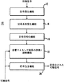
図1は、可聴信号符号器10の機能ブロック図である。符号器10は、オプションとしての記号発生機能12、記号系列発生機能4、記号符号化機能16、音響マスキング効果の評価/調整機能18および可聴信号包含機能20を実装している。望ましくは符号器10はソフトウエア制御コンピュータ・システムを含む。コンピュータは、符号化すべきアナログ可聴信号を標本化するアナログプロセッサを備えている。つまり、再標本化せずにアナログ信号を直接デジタル型式で入力することができる。代替方法として、符号器10は1つまたはそれ以上の個別の信号処理構成部品を含んでいてもよい。
【0021】
記号発生機能12を利用して、情報信号を符号記号の集合に変換する。この機能は、コンピュータ・システムの半導体EPROMのようなメモリ装置の使用によって実行され、このメモリ装置には情報信号に関するインデックスをつけるために適した符号記号のテーブルが予め格納されている。情報信号を或る種の用途のための符号記号に変換するためのテーブルの一例が図2に示されている。このテーブルは、ハードディスク装置またはコンピュータ・システムの他の適切な記憶装置に格納されてもよい。記号発生機能は、EPROMと関連する制御装置のような1つまたはそれ以上の個別部品、論理アレイ、特定用途向け集積回路、または他の適当な装置またはそれらの装置の組み合わせによって実行される。記号発生機能は、図1に示す機能の残りの1つまたはそれ以上の機能を実施する1つまたはそれ以上の装置によって実施されてもよい。
【0022】
記号系列発生機能14は、記号発生機能によって発生した(または符号器10に直接入力された)記号を、符号または情報記号の冗長系列にフォーマットする。フォーマット処理の一部として、或る実施例のマーカーおよび/または同期記号が符号記号の系列に加えられる。符号記号の冗長系列は、バースト・エラーと可聴信号の符号化処理に特に耐えられるように設計されている。或る実施例による符号記号の冗長系列の詳細な説明は、以下の図3A、3B、3Cの考察に関連して与えられている。望ましくは、発生機能14は、マイクロプロセッサ・システムのような処理装置で実施されるか、特定用途向け集積回路や論理アレイのような専用フォーマット装置か、複数の構成部品またはそれらの構成部品の組み合わせによって実施される。記号系列発生機能は、図1に示す機能の残りの1つまたはそれ以上の機能を実施する1つまたはそれ以上の装置によって実施されてもよい。
【0023】
上に注意したように、記号系列発生機能14はオプションである。例えば、符号化処理は、個別の記号発生機能や記号系列発生機能を実行せずに、情報信号が所定の記号系列に直接変換されるように実施される。
【0024】
このように発生した記号系列の各記号は、記号符号化機能16によって複数の単一周波数符号信号に変換される。或る有利な実施例では、記号符号化機能が、各記号に対応する単一周波数符号信号の集合が予め格納されている半導体EPROMのような、コンピュータ・システムのメモリ装置によって実行される。記号と対応する単一周波数符号信号の集合のテーブルの一例が図4に示されている。
【0025】
代替方法として、符号記号の集合は、コンピュータのハードディスク装置や他の適当な記憶装置に格納されてもよい。符号化機能は、EPROMや関連する制御装置のような1つまたはそれ以上の個別部品、論理アレイ、特定用途向け集積回路、または他の適当な装置またはそれらの装置の組み合わせによって実施されてもよい。符号化機能は、図1に示す機能の残りの1つまたはそれ以上の機能を実施する1つまたはそれ以上の装置によって実行されてもよい。
【0026】
代替方法では、個別に機能12、14、16を実行せずに、情報信号から符号化された系列を直接発生してもよい。
【0027】
音響マスキング効果の評価/調整機能18は、記号符号化機能16によって発生する単一周波数符号信号をマスクする入力可聴信号の容量を決定する。機能18は、可聴信号のマスキング能力の決定に基づいて調整パラメータを発生し、このような符号信号が可聴信号に組み込まれた場合、人間の聴取者によって聞きとることができないように、単一周波数符号信号の相対的な大きさを調整する。信号の振幅が小さいことや信号の他の特性のために、可聴信号のマスキング容量が小さいと決定されている場合、調整パラメータは、或る符号信号の大きさを極端に低レベルに、またはその信号を完全に消滅させることがある。反対に、可聴信号のマスキング容量が大きいと決定されている場合は、特定の符号信号のレベルを大きくする調整パラメータを発生して、このような容量を利用することができる。一般にレベルが大きい符号信号は雑音と区別しやすいので、復号装置で検出可能である。このような評価/調整機能の或る有利な実施例のさらなる詳細は、「可聴信号の符号と復号化を含むための装置と方法」というタイトルでJensenほかに交付された、米国特許第5,764,763号および第5,450,490号の中に記載されている。ここでこれらの特許に言及することによりこれらの特許の開示内容のすべてをここで本願に組み入れて援用する。
【0028】
或る実施例では、機能18は、調整パラメータを単一周波数符号信号に適用して、調整された単一周波数符号信号を発生する。この調整された符号信号は、機能20によって可聴信号の中に含められる。代替方法として、機能18は、調整のためと、機能20によって可聴信号に含むための単一周波数符号信号とともに調整パラメータを供給する。さらに別の実施例では、機能18は、機能12、14、16の1つまたはそれ以上と結合して、振幅が調整された(magnitude-adjusted)単一周波数符号信号を直接発生する。
【0029】
或る実施例では、音響マスキング効果の評価/調整機能18は、例えば、図1に示す1つまたはそれ以上の追加機能を実施できるマイクロプロセッサ・システムのような、処理装置の中に実装される。機能18は、特定用途向け集積回路や論理アレイのような専用装置か、複数の個別部品か、あるいはそれらの複数の個別部品の組み合わせによって実行されてもよい。
【0030】
符号包含機能(code inclusion function)20は、単一周波数符号成分と可聴信号を結合して符号化可聴信号を発生する。簡単な実施では、機能20は、単一周波数符号信号を可聴信号に直接加算するだけである。しかし、機能20は、可聴信号に符号信号を被せる(オーバーレイ)ことができる。代替方法として、変調器20は、音響マスキング効果の評価機能18からの入力に従って可聴信号の中の周波数の振幅を変更し、調整された符号信号を含む符号化可聴信号を発生してもよい。その上、符号包含機能は、時間領域または周波数領域のいずれかで実行されてもよい。符号包含機能20は、加算回路またはプロセッサによって実現されてもよい。この機能は、上に説明した、図1に示す機能の残りの1つまたはそれ以上の機能を実施する1つまたはそれ以上の装置によって実施されてもよい。
【0031】
機能12から機能20の1つまたはそれ以上は、1つの装置で実行されてもよい。或る有利な実施例では、機能12、14、16、18が1つのプロセッサで実行され、さらに他の実施例では、図1に示すすべての機能を1つのプロセッサが実行する。その上、機能12、14、16、18の2つまたはそれ以上は、適当な記憶装置で保守されている1つのテーブルによって実行されてもよい。
【0032】
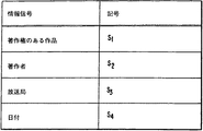
図2は、情報信号を符号記号に変換するための代表的な変換テーブルを示している。図示のように、情報信号には、特定の可聴信号の内容、特性、または他の関連のある要因に関する情報を含めることができる。例えば、オーディオ・プログラムの中に著作権を主張する聞きとれない表示を含めるためには、可聴信号を変更してもよいと考えられている。これに対応して、S1のような記号を使用して、特定の作品の著作権が主張されていることを示すことができる。同様に、ユニークな記号S2を用いて作者を識別できるし、ユニークな記号S3を用いて放送局を識別できる。さらに日付も記号S4で表すことができる。多数の他の種類の情報を情報信号に含めて記号に変換できることは勿論である。例えば、アドレス、コマンド、暗号キーなどの情報も、このような記号に符号化できる。代替方法として、個々の記号に加えてまたは個々の記号の代わりに、記号集合または記号系列を使用して、特定の型式の情報を表してもよい。他の代替方法として、完全な記号言語を実現すれば、いかなる型式の情報信号でも表すことができる。また符号化された情報が可聴信号に関連している必要はない。
【0033】
図3Aは、図1の記号発生機能12で発生しうる記号ストリームを示す模式図であり、図3B、3Cは、図3Aの記号ストリームに応答して、図1の記号系列発生機能14で発生する記号系列を示す模式図である。図3Aから図3Cの中のS1、S2、S3およびS4は、本発明の特徴を示す記号の例として使用されているのであって、本発明の適用可能性を制限することにはならない。例えば、他の記号のいずれか1つまたはそれ以上によって表される情報に関係なく、記号S1、S2、S3またはS4のいずれか1つまたはそれ以上を選択することができる。
【0034】
図3Bは、4つの記号、S1、S2、S3およびS4の入力集合を代表する記号の冗長系列のコア・ユニット(core unit)の一例である。このコア・ユニットは、系列またはマーカーの記号がSAである第1のメッセージ・セグメントで始まり、その後に4つの入力データ記号が続き、その後にそれぞれが系列またはマーカーの記号SBと4つの入力記号を含む、3つの繰り返しメッセージ・セグメントが続く。多くの用途の場合、このコア・ユニットだけで必要なレベルの生存可能性(survivability)を与えるので、十分に冗長性がある。代替方法として、このコア・ユニットは、生存可能性を大きくするようにそれ自体を繰り返えしてもよい。さらにコア・ユニットには、4つまたは5つの記号より多いか少ない記号を有するセグメントとともに、4つのメッセージ・セグメントより多いか少ないセグメントがあってもよい。
【0035】
この例から一般化すると、N個の記号S1, S2, S3 ..... SN-1, SN, は、後に(P-1)個のSB, S1, S2, S3 ..... SN-1, SNを含む繰り返しセグメントが続くSA, S1, S2, S3 ..... SN-1, SN, を含む記号の冗長系列によって表される。この例の中のように、このコア・ユニットは、生存可能性を大きくするようにそれ自体を繰り返すことができる。それだけでなく、復号器が各種セグメント中の対応する記号を認識するように配置されている限り、メッセージ・セグメント中の記号系列を、1セグメントづつ変えることができる。その上、各種のマーカー記号系列とそれらの記号系列の結合を使用し、データ記号に関するマーカーの位置を変えて配置することができる。例えば、系列は、S1, S2 .... SA ..... , SNの形またはS1, S2,, ... , SN, SAの形を取ることができる。
【0036】
図3Cは、4つのデータ記号、S1, S2, S3およびS4の入力集合を代表する冗長記号系列の有利なコア・ユニットの一例を示している。このコア・ユニットは、系列またはマーカーの記号SAで始まり、その後に4つの入力記号が続き、その後に、系列またはマーカーの記号SBが続き、その後に、
【外1】

【0037】
この例から一般化すると、N個の記号S1, S2, S3 ..... SN-1, SN, は、SA, S1, S2, S3 ..... SN-1, SN, SB,
【外2】
【外3】
【0038】
図3に示した冗長系列の著しい強みは、(a)入力記号の異なる配置、(b)入力記号の順番の再配置をしてもしなくても、入力記号の1つまたはそれ以上の代わりに他の記号を含む記号配置、あるいは(c)入力記号と異なる配置、が後に続く、当初の順番で入力記号を使用することである。配置(b)(c)は特に強靱である。何故ならば、記号が符号化されるとき、単一周波数符号信号の多様性が大きくなるからである。入力記号が符号信号の第1のグループの中から一括して符号化されると想定すると、配置(b)(c)は、第1のグループと或る程度オーバーラップしない符号信号の他のグループに符号化される。一般に符号信号の多様性(diversity)がより大きいことは、いくつかの符号信号が可聴信号のマスキング容量内にある可能性を大きくする。
【0039】
図4のテーブルは、系列またはマーカーの記号SA、系列またはマーカーの記号SB、およびN個のデータ記号、S1, S2, S3 ..... SN-1, SNを、M個の単一周波数符号信号、f1x, f2x, f3x, ... f{M-1}x, fMxの対応する集合に変換する代表的な例を示している。ここで、xは特定の記号の識別用下付き文字である。単一周波数符号信号は可聴信号の全周波数範囲にわたって発生するとともに、或る程度、このような周波数範囲の外側で発生するが、この実施例の符号信号は、500Hzから5500Hzまでの周波数範囲内にあるが、異なる周波数範囲として選択されてもよい。一実施例では、M個の単一周波数符号信号の諸々の集合は、或る単一周波数符号信号を共用(share)することができる。しかし、好適実施例では、単一周波数符号信号は、完全に非オーバーラップになっている。その上、全記号が同数の周波数成分によって表される必要はない。
【0040】
図5は、複数ステージの可聴信号符号化システム50を示している。このシステムは、可聴信号52が代表的な可聴信号分配ネットワークに沿って移動していくように、複数の可聴信号符号器を設置して可聴信号を符号化することに成功している。分配の各ステージにおいて、特定のステージに関連のある情報信号とともに可聴信号を符号化することに成功している。望ましくは、それぞれの情報信号を逐次符号化すると、周波数がオーバーラップする符号信号が発生しない。しかしながら、符号化方法の強靱な特性のため、それぞれの符号化された情報信号の周波数成分の間の部分的なオーバーラップは許容可能である。システム50は、記録設備54、放送業者66、中継局76、可聴信号符号器58、70、80、可聴信号記録装置62、聴取者設備86および可聴信号復号器88を含む。
【0041】
記録設備54は、可聴信号を受信して符号化し、符号化可聴信号(encoded audio signal)を記録媒体に記録する装置を含む。詳細には、記録設備54は、可聴信号符号器58と可聴信号記録装置62を含む。可聴信号符号器58は、可聴信号供給(audio signal feed)52と記録情報信号(recording information signal)56を受信し、情報信号56とともに可聴信号を符号化して、符号化可聴信号60を発生する。可聴信号供給52は、例えば、マイクロフォン、記録された可聴信号を再生する装置等のような何らかの従来の可聴信号の発生源によって発生することができる。記録情報信号56は、著作者、内容、作品の規模、著作権の存在、など可聴信号供給52に関する情報を含むことが望ましい。代替方法として、記録情報信号56はいかなる型式のデータを含んでいてもよい。
【0042】
記録装置62は、1つまたはそれ以上の放送業者66に配給することに適している記憶媒体に符号化可聴信号60を記録する従来の装置である。代替方法として、可聴信号記録装置62を完全に省略してもよい。符号化可聴信号60は、記録された記憶媒体の配給を介して、または通信リンク64を介して配給されてもよい。通信リンク64は記録設備54と放送業者66の間を結ぶとともに、放送チャネル、マイクロウエーブ・リンク、有線または光ファイバ接続などが含まれていることが望ましい。
【0043】
放送業者66は、符号化可聴信号60を受信し、放送業者情報信号68とともに符号化可聴信号60をさらに符号化して、2回符号化された(twice-encoded)可聴信号72を発生し、送信経路74に沿って、2回符号化された可聴信号72を放送する。放送業者66は、記録設備54から符号化可聴信号60と放送業者情報信号68を受信する可聴信号符号器70を含む。放送業者情報信号68は、識別符号のような放送業者66に関する情報、あるいは放送の時間、日付または特性のような放送プロセスに関する情報、意図された放送信号の受信者などを含むことができる。符号器70は、放送業者情報信号68とともに符号化可聴信号60を符号化して、2回符号化された可聴信号72を発生する。放送業者66と中継局76の間を結ぶ送信経路(パス)74には、放送チャネル、マイクロウエーブ・リンク、有線または光ファイバ接続などが含まれる。
【0044】
中継局76は、放送業者66から2回符号化された可聴信号72を受信し、中継局情報信号78とともにその信号をさらに符号化し、送信経路84を介して3回符号化された可聴信号82を聴取者設備86に送信する。中継局76は、放送業者66から2回符号化された可聴信号72と中継局情報信号78を受信する可聴信号符号器80を含む。中継局情報信号78は、識別符号のような中継局76に関する情報、または放送時間、日付または特性のような放送信号を中継するプロセスに関する情報、意図された中継した信号の受信者など、を含むことが望ましい。符号器80は、中継局情報信号78とともに2回符号化された可聴信号72を符号化して、3回符号化された可聴信号82を発生する。送信経路84は、中継局76と聴取者設備86との間を結び、放送チャネル、マイクロウエーブ・リンク、有線または光ファイバ接続などを含むことができる。オプションとして、送信経路84は音響送信経路であってもよい。
【0045】
聴取者設備86は、中継局76から3回符号化された可聴信号82を受信する。聴取者推定の用途(オウディエンス・エスティメイト・アプリケーション)では、聴取者設備86は聴取者である人間が可聴信号82の音響再生を知覚することができる場所に配置される。可聴信号82が電磁信号として送信される場合、聴取者設備86は聴取者である人間のためにその信号を音響的に再生する装置を含むことが望ましい。しかし、可聴信号82が記憶媒体に格納される場合は、聴取者設備86は記憶媒体から信号82を再生する装置を含むことが望ましい。
【0046】
音楽の識別やコマーシャルのモニタのような他の用途の場合、聴取者設備86ではなく、モニタ設備が採用される。このようなモニタ設備の場合、可聴信号82を処理して、音響を再生せずに符号化されたメッセージを受信することが望ましい。
【0047】
可聴信号復号器88は、可聴信号、またはオプションで音波信号として3回符号化された可聴信号82を受信することができる。復号器88は、可聴信号82を復号して、可聴信号に符号化された1つまたはそれ以上の情報信号を復元することができる。望ましくは、復元した情報信号は、聴取者設備86で処理されるか、後で処理するために記憶媒体に記録される。
【0048】
代替方法として、聴取者への視覚表示として復元した情報信号を画像に変換してもよい。
【0049】
或る代替実施例では、記録設備54がシステム50から省略されている。例えば、オーディオの生演奏を表す可聴信号供給52が、符号化と放送のため、直接放送業者66に提供される。したがって、放送業者情報信号68は、著作者、内容、作品の規模、著作権の存在、など可聴信号供給52に関する情報をさらに含むことができる。
【0050】
他の代替実施例では、中継局76がシステム50から省略されている。放送業者66は、放送業者66と聴取者設備86の間を結ぶように改造されている送信経路74を介して、2回符号化された可聴信号72を聴取者設備86に直接提供する。さらなる代替方法として、記録設備54と中継局76の双方がシステム50から省略されている。
【0051】
他の代替実施例では、放送業者66と中継局76がシステム50から省略されている。オプションとして、通信リンク64は、記録設備54と聴取者設備86の間を結ぶように改造され、両者の間を符号化可聴信号60を運ぶ。望ましくは、可聴信号記録装置62は、後で聴取者設備86に送られる記憶媒体に符号化可聴信号60を記録する。聴取者設備86にあるオプションとしての再生装置は、復号化および/または音響再生のために、記憶媒体から符号化可聴信号を再生する。
【0052】
図6は、聴取者を推定する用途に使用する個人用携帯計器40の一例を提供している。計器90は、点線(phantom line)で示されていて、聴取者の一人で運べる大きさと形状をしたハウジング92を含む。例えば、この容器は、ページャー装置と同じ大きさと形状にしてもよい。
【0053】
マイクロフォン93はハウジング92の中にあり、受信した符号化可聴信号を含む音響エネルギーをアナログ電気信号に変換する。アナログ・デジタル変換器でアナログ信号がデジタルに変換されると、このデジタル信号はデジタル信号処理プロセッサ(DSP)95に供給される。DSP95は、マイクロフォン93で受信された音響エネルギーの中の所定の符号の存在を検出して、人が運ぶ個人用携帯計器90が或る局またはチャネルの放送に露出されていたことを示すため、本発明による復号器を実装している。そうなっていると、DSP95は、関連する時間信号とともにそのような検出を表す信号をDSPの中のメモリに格納する。
【0054】
計器90は、DSP95に結合された赤外線送信器/受信器97のようなデータ送信器/受信器を含む。送信器/受信器97は、DSP95が、例えば、新しい聴取者調査を実行するために計器90を設定する命令やデータを受信するとともに、複数の計器90からのそのようなデータを処理して、聴取者の推定値を発生する設備に処理したデータを提供することを可能にする。
【0055】
本発明の或る有益な実施例による復号器は、図7の機能ブロック図で示されている。上に説明したように、複数の符号記号とともに符号化される可聴信号は、入力102で受信される。受信した可聴信号は、放送、インターネットまたはそれ以外の伝達された信号か、再生された信号であってもよい。その信号は直接結合された信号か、音響的に結合された信号であってもよい。添付の図面に関連した次の説明から、復号器100が上で開示したフォーマットに配置された符号のほかに符号を検出することができることは理解できるであろう。
【0056】
時間領域で受信された可聴信号の場合、復号器100は、機能106によってそのような信号を周波数領域に変換する。機能106は高速フーリエ変換(FFT)を実行するデジタルプロセッサによって実行されることが望ましいが、代替方法では、離散的コサイン変換(DCT)、チャープ変換(chirp transform)、またはウイノグラード変換アルゴリズム(WFTA)を使用してもよい。このほか、これらの変換機能の代わりに、必要な解を与える時間領域から周波数領域への変換機能ならばどれを使用してもよい。或る実施方法(implementations)では、アナログフィルタやデジタルフィルタ、特定用途向け集積回路、その他の適当な装置またはそれら装置の組み合わせによって機能106を実行することができる。機能106は、図7に示す機能の残りの1つまたはそれ以上の機能を実施する、1つまたはそれ以上の装置によって実施されてもよい。
【0057】
周波数領域に変換された可聴信号は、記号値抽出機能(symbol value derivation function)110の中で処理され、受信した可聴信号に含まれていた各符号記号ごとに記号値のストリームを発生する。発生した記号値は、絶対値または相対値として瞬間的にまたは或る時間にわたって測定された、例えば、信号エネルギー、パワー、音圧レベル、振幅などを表すことができ、さらに1つの値または複数の値として表されてもよい。それぞれが所定の周波数を有する単一周波数成分のグループとして記号が符号化される場合は、これらの記号値が、単一周波数成分の値か、単一周波数成分の値に基づく1つまたはそれ以上の値のいずれかを表すことが望ましい。
【0058】
機能110は、機能110の他の機能のいくつかまたはすべてを有利に実行するデジタル信号処理プロセッサ(DSP)のような、デジタルプロセッサによって実行されてもよい。しかし、機能110は特定用途向け集積回路、または他の適当な装置またはそれら装置の組み合わせによって実行されてもよく、復号器100の残りの機能を実施する手段とは別の装置で実行されてもよい。
【0059】
機能110によって発生した記号値のストリームは、機能116で示されているように、1記号づつ適当な記憶装置の中で時間に対して(over time)累積される。特に機能116は、発生しうる各種記号の記号値を周期的に累積することにより、周期的に繰り返す符号化された記号の復号に使用するときに優れている。例えば、所定の記号がX秒ごとに反復することが予測されると、機能116は、nX秒(n>1)の時間のあいだ記号値のストリームを格納し、格納したnX秒間続く1つまたはそれ以上の記号値ストリームの格納した値に加算する役目をするので、徐々に記号のピーク値(peak symbol values)が累積し、格納した値の信号対雑音比を改善する。
【0060】
機能116は、復号器100の他の機能のいくつかまたはすべてを有利に実行するDSPのような、デジタルプロセッサによって実行される。しかし、機能110は、そのようなプロセッサと離れているメモリ装置を使用して実行されてもよく、あるいは特定用途向け集積回路、他の適当な装置またはそれらの装置の組み合わせによって実行されてもよく、復号器100の残りの機能を実施する手段とは別の装置で実行されてもよい。
【0061】
機能116によって格納された累積記号値は、機能120によって調べられ、符号化されたメッセージの存在を検出し、検出したメッセージを出力126に出力する。機能120は、相関手法または他のパターン一致手法のいずれかによって、格納した累積値または累積値を処理した値と格納されているパターンを一致させることにより実行される。しかし、機能120は、累積記号値のピーク値とそれらのピーク値の相対時間を調べることにより有利に実行され、累積記号値の符号化されたメッセージを再構築することができる。この機能は、機能116によって記号値の第1のストリームが格納された後、および/または各後続ストリームが第1のストリームに加算された後に実行されるので、格納された記号値の累積ストリームの信号対雑音比が有効なメッセージ・パターンを表すと、メッセージが検出される。
【0062】
図8は、DSPによって実行される本発明の優れた一実施例による復号器の流れ図である。ステップ130は、例えば、アナログ信号が(図6の実施例のような)マイクロフォンまたはRF受信器で拾われる場合に、符号化可聴信号がアナログの型式で受信される用途のために設けられている。
【0063】
図8の復号器は、それぞれが1000Hzから3000Hzまでの周波数範囲の中の複数の所定の周波数成分、例えば10個の内容を含む符号記号を検出することに特に良く適応している。この復号器は、図3Cに示されている各記号が0.5秒の間隔を占める記号系列を有するメッセージを検出するように、特別に設計されている。この代表的実施例では、記号の集合は12個の記号を含み、各記号は10個の所定の周波数成分を有し、これらの周波数成分のどれもがこの記号集合の他の記号によって共用されないと想定する。図8の復号器は、各種周波数帯域に配置された成分とともに、いろいろな数の符号記号、いろいろな数の成分、各種記号系列および記号継続時間を検出するように容易に改造できることは理解できるであろう。
【0064】
各種成分を分離するために、DSPは、連続する所定の間隔に入る可聴信号の標本(サンプル)に繰り返しFFTを実行する。間隔はオーバーラップしてもよいが、これは要求されていない。代表的実施例では、復号器動作の1秒間ごとにオーバーラップするFFTが10回実行される。したがって、各記号時間のエネルギーは5回のFFT内に入る。FFTをウインドウにすることができるが、復号器を簡単にするために省略されている。ステップ134、138で示されるように、標本が格納され、必要を満たす十分な数が使用可能になると、新しいFFTが実行される。
【0065】
この実施例では、周波数成分の値は相対的につくられる。つまり、各成分の値は、次のように作られる信号対雑音比(SNR)として表される。FFTの各周波数ビンの中にはどの記号の周波数成分で入ることができるが、このビンの中のエネルギーは、対応する各SNRの分子になる。各SNRの分母は、隣接するビンの値の平均値として決定される。例えば、周囲の8つのビンのエネルギーの値のうち、7つの平均値を使用できると、例えば、その符号の周波数成分の近くにある可聴信号成分から生じるかもしれない大きなビンのエネルギー値の影響を避けるため、その8個のうちの最大値が無視される。例えば、雑音または可聴信号成分のため、符号成分のビンの中に現れる大きなエネルギー値が与えられると、SNRは適切に制限される。この実施例では、SNR≧6.0であれば、SNRは6.0に制限されるが、これとは違う最大値が選択されるかもしれない。
【0066】
ステップ142に示されているとともに図9に模式的に示されているように、各FFTと、存在するかもしれない各記号に対応する10個のSNRが結合されて記号SNRを形成すると、これらのSNRは循環型(circular)記号SNRバッファに格納される。或る実施例では、所定の記号の10個のSNRが単純に加算されるが、他の方法を使用してSNRを結合してもよい。
【0067】
図9で示すように、A、Bおよび0から9の12個の記号ごとの記号SRNは、別々の系列、つまり50回のFFTの各FFTごとに1つの記号SNRとして、記号SNRバッファに格納される。以下に説明するように、50回のFFTで発生した値を記号SNRバッファに格納してしまうと、新しい記号SNRと前に格納した値が結合される。
【0068】
記号SNRバッファが一杯になると、ステップ146で検出される。或る有利な実施例では、ステップ152は多くの用途ではオプションであるが、このステップで格納したSNRが調整され、雑音の影響を小さくする。このオプションのステップでバッファが一杯になるたびに、それぞれの列に格納された全記号SNRの平均値を求めることにより、バッファの各記号(列)ごとに雑音が求められる。次に、雑音の効果を補償するために、この平均値つまり「雑音」の値が、対応する列に格納された記号SNRのそれぞれから減算される。このように、短時間だけ現れるので有効に検出されなかった「記号」は、或る時間にわたって(over time)平均される。図3を参照すると、復号器の雑音を大きくすることをさけるため、望ましくは、メッセージの最初の半分の中で(つまり、記号系列、SA、S1、S2、S3、S4の中で)同じ記号が2回出現しないように、符号化方法に制約が加えられる。
【0069】
雑音レベルを減算することにより、記号SNRの調整が終わっていると、ステップ156で、復号器はバッファの中の最大SNR値のパターンを調べることにより、メッセージを復元しようと試みる。或る実施例では、各記号ごとの最大SNR値は、逐次重み付け(6 10 10 10 6)に正比例する系列の中の値に重み付けし、重み付けされたSNRを加算して、系列の中の第3のSNRの時間の中央にある比較用SNR(comparison SNR)を発生することにより、5個の隣接するSNRのグループを連続して結合する処理に入れられる。この処理は、各記号の50回のFFTの全時間中、段階的(progressibly)に実行される。例えば、FFT時間(ピリオド)1からFFT時間5までの時間で、記号「A」の5個のSNRの第1のグループが重み付けされて加算され、FFT時間3の比較用SNRを発生する。次に、FFT時間2からFFT時間6のSNRを使用して別の比較用SNRを発生するというように、FFT時間3からFFT時間48まで、中心にある比較用SNRが求められるまで上記動作が続けられる。しかし、他の手段を使用してメッセージを復元してもよい。例えば、5個のSNRより多いか少ないSNRを結合してもよく、重み付けをせずに、あるいは非線形的にそれらのSNRを結合してもよい。
【0070】
比較用SNR値が得られていると、復号器はメッセージ・パターンを求めるために比較用SNRの値を調べる。最初に、マーカー符号記号SAとSBが配置される。この情報が得られると、復号器は、データ記号のピーク値を検出しようと試みる。第1セグメントの各データ記号と、第2セグメントの対応するデータ記号との間の所定のオフセットの使用は、検出したメッセージの有効性をチェックすることができる。つまり、両マーカーが検出され、第1セグメントの各データ記号と、それらのデータ記号に対応する第2セグメントの中のデータ記号との間で同じオフセットが観察されると、有効なメッセージが受信されているに違いないと考えてもよい。
【0071】
図3Cと図9の双方を参照すると、バッファの先頭は、メッセージの先頭に対応し(通常はこうならない)、図示のように、記号「A」の比較用SNRのピーク値Pは、第3のFFT時間に出現するはずである。次に復号器は、8回目のFFT時間中に第1のデータ記号「0」から「9」に対応する位置に次のピーク値が現れることを予測する。この例では、第1のデータ記号が「3」であると想定する。最後のデータ記号が「4」で、δの値が2だとすると、図9に示すように、復号器は、FFT時間48で記号「6」のピーク値を見つける。ステップ162、166に示すように、このようにメッセージが検出されるとすれば、(つまり、予測したところに現れたデータ記号と、終始、同じオフセットによりマーカーが検出されると)メッセージは記録されるか出力されて、SNRバッファはクリアされる。
【0072】
しかし、メッセージが見つからないとすれば、可聴信号の次の部分について、オーバラップするFFTがさらに50回実行され、それで発生する記号SNRは、既に循環型バッファの中にある記号SNRに加算される。雑音の調整処理が前と同様に実行されると、復号器は再びメッセージ・パターンを検出しようと試みる。この処理は、メッセージが検出されるまで連続して繰り返される。代替方法では、限定された回数だけ処理が実行される。
【0073】
本発明の趣旨を逸脱することなく、メッセージの構造、タイミング、信号経路、検出モードなどに依存して復号器の動作を改造できることは、前述の説明から明らかである。例えば、メッセージを検出するために、SNRを格納する代わりに、FFTの結果を直接格納してもよい。
【0074】
図10は、同様にDSPによって実装される、さらに優れた実施例による他の復号器の流れ図である。図10の復号器は、4個のデータ記号が続くマーカー記号を含む5個の符号記号系列の繰り返しを検出することに特に適応しており、各符号記号は複数の所定の周波数成分を有して、メッセージ系列の中に0.5秒の継続時間を有する。各記号は10個のユニークな周波数成分によって表され、記号の集合は、図3Cの符号の中のように、A、Bおよび0から9までの12個の異なる記号を含むと想定する。しかし、図9の実施例は、各記号が1つまたはそれ以上の周波数成分で表されるいかなる数の記号でも検出するように容易に改造されることは、理解できるであろう。
【0075】
図10に示す復号化処理に使用されるいくつかのステップは図8の復号化処理に対応しており、同じ参照番号で示されているので、これらのステップの説明はしない。図10の実施例は、12個の記号幅掛ける150回のFFTの時間長の循環型(サーキュラー)バッファを使用する。バッファが一杯になると、最も古い記号SNRの値と新しい記号SNRが入れ替わる。実際に、バッファは記号SNRの値の15秒間のウィンドウを格納する。
【0076】
ステップ174に示すように、循環型バッファが一杯になると、ステップ178でバッファの内容が調べられ、メッセージ・パターンの存在を検出する。一杯になると、FFTを実行するたびに1回、ステップ178のパターン探索を実行できるように、バッファは常に一杯のままになっている。
【0077】
各5個の記号メッセージは、21/2秒ごとに繰り返すので、各記号は21/2秒の間隔または25回のFFTごとに繰り返す。バースト・エラーなどの効果を補償するために、SNRのR1からR150は、繰り返しメッセージの対応する値を加算することによって結合され、次に示すように、25個の結合されたSNRの値、SNRn、n=1,2...25が得られる。
このように、バースト・エラーが信号間隔iの損失になると、6個のメッセージ間隔の1つだけが失われているので、結合されたSNRの値の本質的な性質は、この事象によって影響されないようである。
【0079】
結合されたSNRの値が決定されると、復号器は、その結合されたSNRの値によって示されるマーカー記号のピーク値の位置を検出し、マーカーの位置とデータ記号のピーク値に基づいてデータ記号系列を取り出す。
【0080】
ステップ182、183で示されるように、メッセージが形成されると、そのメッセージは記録される。しかし、図8の実施例と異なり、バッファはクリアされない。その代わり、復号器はSNRのさらなる集合をバッファにロードして、メッセージの探索を継続する。
【0081】
図8の復号器と同様、本発明の範囲を逸脱することなく、各種メッセージの構造、メッセージのタイミング、信号経路、検出モードなどのために図10の復号器を改造することは、前述の説明から明らかである。例えば、図10の実施例のバッファは、他の適当な記憶装置と置き換えてもよく、バッファの大きさを変えてもよく、SNR値のウィンドウの大きさを変えてもよく、および/または記号の反復時間を変えてもよい。また或る優れた実施例では、信号のSNRを計算し格納して、それぞれの記号値を表す代わりに、発生しうる他の記号に関連する各記号の値の尺度、例えば、発生しうる各記号の大きさの順位付けが使用される。
【0082】
聴取者測定の用途で特に有用な変更では、比較的多数のメッセージ間隔が別々に格納され、聴取者の内容の後ろ向きの分析(retrospective analysis)をしてチャネル変更を検出できるようにする。他の実施例では、図8の復号方法に使用するために複数のバッファが使用され、各バッファは異なる数の間隔のデータを累積する。例えば、1つのバッファは、1つのメッセージ間隔、他の2つの累積された間隔、第3の4つの間隔および第4の8個の間隔を格納することができる。各バッファの内容に基づく別々の検出は、チャネル変更を検出するために使用される。
【0083】
以上、本発明の実施例と、その各種改造を詳細に説明してきたが、この発明は、これらの精緻な実施例と各種変更に限定されるものではなく、特許請求の範囲で定義されているように、本発明の範囲と趣旨を逸脱することなく、当業者によって他の改造や変更を実行できることを理解すべきである。
【図面の簡単な説明】
【図1】 符号化装置の機能ブロック図を示す図。
【図2】 可聴信号の中で情報を符号化する方法を説明するときに引用するテーブルを示す図。
【図3A】 可聴信号を符号化する方法を示す模式的ブロック図を示す図。
【図3B】 可聴信号を符号化する方法を示す模式的ブロック図を示す図。
【図3C】 可聴信号を符号化する方法を示す模式的ブロック図を示す図。
【図4】 可聴信号を符号化する方法を示す他の模式的ブロック図を示す図。
【図5】 複数ステージ可聴信号符号化システムを示すブロック図を示す図。
【図6】 個人用携帯計器の機能ブロック図を示す図。
【図7】 復号化装置を示す機能ブロック図を示す図。
【図8】 符号化されたデータから情報符号を検索する方法を示す流れ図を示す図。
【図9】 図8の方法を実行するときに使用される循環型SNRバッファの模式図を示す図。
【図10】 符号化されたデータから情報符号を検索する他の方法を示す流れ図を示す図。[0001]
(Background of the Invention)
The present invention relates to a method and apparatus for extracting an information signal from an encoded audio signal.
[0002]
There are various motivations to incorporate so-called “watermarking” in the audible signal permanently, ie in such a way that it cannot be erased. Such an acoustic watermark displays, for example, the author, content, lineage of the work, existence of copyright, etc. of the audible signal so marked. Alternatively, information about the signal itself or other information unrelated to the signal itself may be incorporated into the audible signal. Information may be incorporated into the audible signal for a variety of purposes, such as identification numbers, ie addresses and commands, whether or not related to the signal itself.
[0003]
There is great interest in encoding an audible signal with information to generate a coded audible signal having substantially the same perceptible characteristics as the original audible signal that is not encoded. A recently successful technique uses the psychoacoustic masking effect of the human auditory system, which allows certain sounds to be received along with other sounds. It is known that humans cannot perceive it.
[0004]
An example of a particularly successful use of the psychoacoustic masking effect is described in US Pat. Nos. 5,450,490 and 5,764,763 (by Jensen et al.), And the information in this description includes the ability to mask audible signals. Is represented by a multi-frequency code signal incorporated in an audible signal. The encoded audible signal is suitable for transmission / reception of a broadcast as well as recording and reproduction. When received, the audible signal is processed to detect the presence of the multi-frequency code signal. Sometimes only a portion of the multi-frequency code signal inserted into the original audible signal, eg some single frequency code components, are detected in the received audible signal. When a sufficiently satisfactory amount of code components is detected, the information signal itself can be restored.
[0005]
In general, an acoustic signal with a low level of amplitude has minimal capacity, and if there is no amplitude at all, the information signal is acoustically masked. Such low level amplitudes may occur, for example, during conversation pauses, during interludes of a concert, or even in some types of music. While the low level amplitude lasts for a long time, it may be difficult to incorporate the code signal into the audible signal without being different from the original audible signal so that the encoded audible signal can be perceived acoustically.
[0006]
A further problem is that burst errors occur during transmission or playback of the encoded audible signal. Burst errors may appear as temporally contiguous segments of signal error. In general, such errors are unpredictable and have a significant effect on the content of the encoded audible signal. Burst errors typically include, for example, overlapping signals from various transmission channels, occurrences of system power spikes, interruptions in normal transmission operations, spread of contamination due to (intentional or unintentional) noise, etc. Arising from malfunctions of the transmission channel or playback device due to some external interference. In such a circumstance in a transmission system, some of the transmitted encoded audible signal becomes completely unreceivable or changes significantly. If the encoded audible signal is not retransmitted, the affected part of the encoded audible signal is not restored at all, otherwise changes to the encoded audible signal make it impossible to detect the embedded information signal Might be. In many applications, such as radio broadcasting and television broadcasting, real-time retransmission of encoded audible signals cannot be easily performed.
[0007]
In a system for acoustically reproducing an audible signal recorded on a medium, a burst error may occur in the reproduced acoustic signal due to various factors. Usually, irregularities in the recording medium caused by damage, obstacles or wear will make certain parts of the recorded audible signal unreproducible or remarkably change. Similarly, burst type errors may occur during sound reproduction of recorded audible signals due to misalignment or obstruction of the recording or playback mechanism associated with the recording medium. In addition to the acoustic characteristics of the listening environment, spatial irregularities may occur in the acoustic energy distribution due to acoustic limitations of the speakers. Due to such irregularities, a burst error occurs in the received acoustic signal, hindering code recovery.
[0008]
(Objectives and summary of the present invention)
Accordingly, it is an object of the present invention to provide a system and method that detects code symbols in an audible signal to mitigate problems caused by low level signals and burst error times. .
[0009]
It is another object of the present invention to provide a system and method that operates reliably under adverse conditions.
[0010]
It is a further object of the present invention to provide such a system and method that is robust.
[0011]
In accordance with aspects of the present invention, systems and methods are provided for decoding at least one message symbol (symbol) represented by a plurality of code symbols in an audible signal. These systems and methods receive first and second code symbols representing a common message symbol being displaced in time in the audio signal, and the first code The first signal value representing the symbol and the second signal value representing the second code symbol are accumulated (accumulated), and the accumulated first and second signal values are examined to detect a common message symbol. Means and steps.
[0012]
According to another aspect of the invention, a system is provided for decoding at least one message symbol represented by a plurality of code symbols in an audible signal. The system includes an input device that receives first and second code symbols that represent a common message symbol that changes position in time in an audible signal, a first signal value that represents the first code symbol, and a first signal value. Programmed to accumulate a second signal value representing two code symbols, programmed to examine the accumulated first and second signal values to detect a common message symbol, and further to an input device And a digital processor for receiving data representing the first and second code symbols from the input device.
[0013]
In one embodiment, the first and second signal values are accumulated by storing the values separately, and the common message symbol is detected by examining both of these separately stored values. The first and second signal values are, for example, signal values taken from a plurality of other signal values such as individual code frequency component values, or a single measure of the magnitude of one code frequency component. A signal value can be represented. Furthermore, the retrieved value can be determined as a linear combination of a plurality of signal values, such as a weighted value or a sum of unweighted values, or as a non-linear function of the values.
[0014]
In a further embodiment, the first and second signal values are accumulated by generating a third signal value derived from the first and second signal values. In some embodiments, the third signal value is retrieved through a linear combination of signal values as a weighted or unweighted sum or as a non-linear function of the values.
[0015]
Other objects, features and advantages of the present invention will become readily apparent upon reading the following detailed description in conjunction with the accompanying drawings. In the accompanying drawings, the same components are identified by the same reference numerals.
[0016]
Detailed Description of Advantageous Embodiments
The present invention relates to the use of very robust coding that converts information into redundant sequences of code symbols. In some embodiments, each code symbol is represented by a different set of single frequency code signals, while in other embodiments, various code symbolsIsAs an option,Share a single frequency signalOrGiven a method that does not assign a given frequency component to a given symbolIsCan. The redundant sequence of symbols is embedded in the audible signal and is not perceived by the listener, but generates a reconstructable encoded audible signal.
[0017]
The redundant code symbol sequence is very suitable for incorporation into an audible signal having a small masking capacity, such as an audible signal having a large number of low amplitude portions. Moreover, when incorporated into an audible signal, the redundant sequence of code symbols prevents quality degradation due to burst errors that affect the temporally audible signal. As explained so far, such errors can be caused by incomplete recording of the audible signal, reproduction and / or storage processing, loss and / or irregularities in the noisy channel or acoustic space. This may result in transmission, incomplete recording, playback and / or storage.
[0018]
In an advantageous embodiment, in order to recover the encoded information, the encoded audio signal is examined in an attempt to detect the presence of predetermined single-frequency code components. During the encoding process, some single frequency code components may not have been incorporated into the audible signal at these signal intervals due to insufficient masking capacity of the audible signal at certain signal intervals. Due to a burst error that destroys part of the encoded audible signal, certain code symbols may be removed from the encoded audible signal, or error signals such as noise may be inserted into the encoded audible signal. . Examining the encoded audible signal in this way appears to reveal a very distorted appearance of the original sequence of sets of single frequency code signals representing information.
[0019]
The single frequency code component reconstructed with a special signal containing an error erroneously detected as a code signal is preferably processed to recognize the original sequence of code symbols. The code symbol detection operation and the processing operation are particularly adapted to use the strength of the encoding method. As a result, the detection and processing method of the present invention improves tolerance.
[0020]
FIG. 1 is a functional block diagram of an
[0021]
The
[0022]
The symbol
[0023]
As noted above, the symbol
[0024]
Each symbol of the generated symbol sequence is converted into a plurality of single frequency code signals by the
[0025]
Alternatively, the set of code symbols may be stored on a computer hard disk drive or other suitable storage device. The encoding function can be achieved by one or more individual components, such as EPROM and associated control devices, logic arrays, application specific integrated circuits, or other suitable devices or combinations of these devices.May be implemented. The encoding function is performed by one or more devices that perform one or more of the remaining functions shown in FIG.May be executed.
[0026]
In an alternative method, the encoded sequence may be generated directly from the information signal without performing the
[0027]
The acoustic masking effect evaluation /
[0028]
In some embodiments,
[0029]
In some embodiments, the acoustic masking effect assessment /
[0030]
A
[0031]
One or more of
[0032]
FIG. 2 shows a typical conversion table for converting information signals into code symbols. As shown, the information signal may include information regarding the content, characteristics, or other relevant factors of a particular audible signal. For example, it is contemplated that the audible signal may be changed to include an inaudible display claiming copyright in the audio program. Correspondingly, S1Can be used to indicate that the copyright of a particular work is claimed. Similarly, the unique symbol S2Can be used to identify the author and the unique symbol SThreeCan be used to identify broadcast stations. The date is also a symbol SFourCan be expressed as Of course, many other types of information can be included in the information signal and converted into symbols. For example, information such as an address, a command, and an encryption key can be encoded into such a symbol. Alternatively, in addition to or in place of individual symbols, symbol sets or symbol sequences may be used to represent a particular type of information. As another alternative, any type of information signal can be represented if a complete symbolic language is implemented. Also, the encoded information need not be related to the audible signal.
[0033]
3A is a schematic diagram showing a symbol stream that can be generated by the
[0034]
FIG. 3B shows four symbols, S1, S2, SThreeAnd SFourThis is an example of a core unit of a redundant series of symbols representing the input set. This core unit has a series or marker symbol of SAStarting with the first message segment, followed by four input data symbols, each of which is a sequence or marker symbol SBFollowed by three repeated message segments. For many applications, this core unit alone provides the required level of survivability and is sufficiently redundant. As an alternative, the core unit may repeat itself to increase viability. In addition, the core unit may have more or fewer segments than four message segments, as well as segments with more or fewer than four or five symbols.
[0035]
Generalizing from this example, N symbols S1, S2, SThree ..... SN-1, SN, Later (P-1) SB, S1, S2, SThree ..... SN-1, SNFollowed by a repeating segment containingA, S1, S2, SThree ..... SN-1, SN, Is represented by a redundant sequence of symbols containing. As in this example, this core unit can repeat itself to increase its viability. In addition, as long as the decoder is arranged to recognize the corresponding symbols in the various segments, the symbol sequence in the message segment can be changed one segment at a time. In addition, various marker symbol sequences and combinations of these symbol sequences can be used to place the markers relative to the data symbols. For example, the series is S1, S2 .... SA ....., SNShape or S1, S2 ,, ..., SN, SACan take the form of
[0036]
FIG. 3C shows four data symbols, S1, S2, SThreeAnd SFourAn example of an advantageous core unit of a redundant symbol sequence representative of a set of inputs is shown. This core unit is a series or marker symbol SAFollowed by four input symbols, followed by a series or marker symbol SBFollowed by
[Outside 1]
[0037]
Generalizing from this example, N symbols S1, S2, SThree ..... SN-1, SN, SA, S1, S2, SThree ..... SN-1, SN, SB,
[Outside 2]
[Outside 3]
[0038]
The redundant sequence shown in FIG.Remarkable strength(A) a different arrangement of input symbols, (b) a symbol arrangement that includes other symbols in place of one or more of the input symbols, with or without rearrangement of the order of the input symbols, or ( c) Use the input symbols in the original order, followed by an arrangement different from the input symbols. Arrangements (b) and (c) are particularly tough. This is because the diversity of a single frequency code signal increases when symbols are encoded. Assuming that the input symbols are collectively encoded from the first group of code signals, the arrangements (b) and (c) are other groups of code signals that do not overlap to some extent with the first group. Is encoded. In general, the greater diversity of code signals means that some code signals are within the masking capacity of the audible signal.possibilityIncrease
[0039]
The table of FIG. 4 shows a sequence or marker symbol SA, a sequence or marker symbol SB, and N data symbols, S1, S2, S3 ..... SN-1, SN, M single frequencies A representative example of conversion into a corresponding set of code signals, f1x, f2x, f3x,... F {M-1} x, fMx is shown. Here, x is a subscript for identifying a specific symbol. A single frequency code signal occurs over the entire frequency range of the audible signal and to some extent outside such a frequency range, but the code signal of this embodiment is within the frequency range of 500 Hz to 5500 Hz. There are different frequency ranges selectedMay. In one embodiment, various sets of M single frequency code signals can share a single frequency code signal. However, in the preferred embodiment, the single frequency code signals are completely non-overlapping. Moreover, all symbols need not be represented by the same number of frequency components.
[0040]
FIG. 5 shows a multi-stage audible
[0041]
The
[0042]
The
[0043]
[0044]
[0045]
The
[0046]
For other applications, such as music identification and commercial monitoring, monitor equipment is employed rather than
[0047]
The
[0048]
As an alternative, the information signal restored as a visual display to the listener may be converted into an image.
[0049]
In some alternative embodiments, the
[0050]
In other alternative embodiments, the
[0051]
In other alternative embodiments,
[0052]
FIG. 6 provides an example of a personal portable instrument 40 used for the purpose of estimating the listener.
[0053]
Microphone 93 is in
[0054]
[0055]
A decoder according to an advantageous embodiment of the invention is illustrated in the functional block diagram of FIG. As explained above, an audible signal encoded with a plurality of code symbols is received at
[0056]
For audible signals received in the time domain, the decoder 100 converts such signals to the frequency domain by
[0057]
The audible signal converted to the frequency domain is processed in a symbol
[0058]
[0059]
The stream of symbol values generated by
[0060]
[0061]
The accumulated symbol value stored by
[0062]
FIG. 8 is a flow diagram of a decoder according to a preferred embodiment of the present invention executed by a DSP. Step 130 is provided for applications in which the encoded audible signal is received in an analog form, for example when the analog signal is picked up by a microphone or RF receiver (such as the embodiment of FIG. 6). .
[0063]
The decoder of FIG. 8 is particularly well adapted to detecting code symbols each containing a plurality of predetermined frequency components, for example 10 contents, each in the frequency range from 1000 Hz to 3000 Hz. This decoder is specially designed to detect messages with a symbol sequence in which each symbol shown in FIG. 3C occupies an interval of 0.5 seconds. In this exemplary embodiment, the set of symbols includes 12 symbols, each symbol10Suppose that it has a predetermined frequency component and none of these frequency components are shared by other symbols in this symbol set. Of FIG.RecoveryIt will be appreciated that the encoder can easily be modified to detect various numbers of code symbols, various numbers of components, various symbol sequences and symbol durations, as well as components located in various frequency bands.
[0064]
In order to separate the various components, the DSP repeatedly performs FFT on a sample (sample) of an audible signal that falls within a predetermined predetermined interval. The intervals may overlap, but this is not required. In an exemplary embodiment, 10 FFTs are performed that overlap every second of the decoder operation. Therefore, the energy of each symbol time falls within 5 FFTs. The FFT can be windowed but is omitted for simplicity of the decoder. As shown in
[0065]
In this embodiment, the value of the frequency component is relatively generated. That is, the value of each component is expressed as a signal-to-noise ratio (SNR) created as follows. Any symbol frequency component can be entered in each frequency bin of the FFT, but the energy in this bin becomes the numerator of each corresponding SNR. The denominator of each SNR is determined as the average value of adjacent bin values. For example, if seven average values of the surrounding eight bin energy values can be used, for example, the effect of large bin energy values that may result from audible signal components near the frequency component of the sign. To avoid it, the maximum of the 8 is ignored. For example, given the large energy values that appear in the bins of the code component due to noise or audible signal components, the SNR is appropriately limited. In this embodiment, if SNR ≧ 6.0, the SNR is limited to 6.0, but a different maximum value may be selected.
[0066]
As shown in
[0067]
As shown in FIG. 9, the symbol SRN for each of the twelve symbols A, B and 0 to 9 is stored in the symbol SNR buffer as one symbol SNR for each FFT of a separate sequence, ie, 50 FFTs. Is done. As will be described below, if a value generated in 50 FFTs is stored in the symbol SNR buffer, the new symbol SNR and the previously stored value are combined.
[0068]
When the symbol SNR buffer is full, it is detected at
[0069]
When the symbol SNR adjustment has been completed by subtracting the noise level, in
[0070]
Once the comparison SNR value has been obtained, the decoder examines the comparison SNR value to determine the message pattern. First, the marker code symbol SAAnd SBIs placed. Once this information is obtained, the decoder attempts to detect the peak value of the data symbol. The use of a predetermined offset between each data symbol of the first segment and the corresponding data symbol of the second segment can check the validity of the detected message. That is, if both markers are detected and the same offset is observed between each data symbol in the first segment and the data symbol in the second segment corresponding to those data symbols, a valid message is received. You may think that it must be.
[0071]
Referring to both FIG. 3C and FIG. 9, the head of the buffer corresponds to the head of the message (which is not usually the case), and as shown, the peak value P of the comparison SNR of symbol “A” is the third Should appear at the FFT time. Next, the decoder predicts that the next peak value will appear at the position corresponding to the first data symbol “0” to “9” during the eighth FFT time. In this example, it is assumed that the first data symbol is “3”. Assuming that the last data symbol is “4” and the value of δ is 2, the decoder finds the peak value of symbol “6” at
[0072]
However, if the message is not found, the overlapping FFT is performed 50 more times for the next part of the audible signal, and the resulting symbol SNR is added to the symbol SNR already in the circular buffer. . Noise adjustment processingBeforeThe decoder will attempt to detect the message pattern again. This process is repeated continuously until a message is detected. In the alternative method, the process is performed a limited number of times.
[0073]
It will be apparent from the foregoing description that the decoder operation can be modified depending on the message structure, timing, signal path, detection mode, etc. without departing from the spirit of the invention. For example, in order to detect a message, instead of storing the SNR, the result of the FFT may be directly stored.
[0074]
FIG. 10 is a flowchart of another decoder according to a further preferred embodiment, also implemented by a DSP. The decoder of FIG. 10 is particularly adapted to detect a repetition of 5 code symbol sequences including a marker symbol followed by 4 data symbols, each code symbol having a plurality of predetermined frequency components. Thus, the message sequence has a duration of 0.5 seconds. Assume that each symbol is represented by 10 unique frequency components, and that the set of symbols includes A, B, and 12 different symbols from 0 to 9, as in the code of FIG. 3C. However, it will be appreciated that the embodiment of FIG. 9 can be readily modified to detect any number of symbols, each symbol represented by one or more frequency components.
[0075]
Some steps used in the decoding process shown in FIG. 10 correspond to the decoding process in FIG. 8 and are denoted by the same reference numerals, so these steps will not be described. The embodiment of FIG. 10 uses 12 symbol widths multiplied by 150 FFT time length circular buffers. When the buffer is full, the oldest symbol SNR value and the new symbol SNR are swapped. In practice, the buffer stores a 15 second window of the value of the symbol SNR.
[0076]
As shown in
[0077]
Each of the 5 symbol messages is 21/2Each symbol is 2 because it repeats every second1/2Repeat every second or every 25 FFTs. SNR R to compensate for effects such as burst errors1To R150Are combined by adding the corresponding values of the repetitive message and, as shown below, 25 combined SNR values, SNRn, N = 1,2 ... 25 is obtained.
Thus, when a burst error results in a loss of signal interval i, the intrinsic nature of the combined SNR value is not affected by this event since only one of the six message intervals is lost. It seems.
[0079]
Once the combined SNR value is determined, the decoder detects the peak value position of the marker symbol indicated by the combined SNR value, and the data is based on the marker position and the peak value of the data symbol. Extract a symbol series.
[0080]
As shown in
[0081]
Similar to the decoder of FIG. 8, modifying the decoder of FIG. 10 for various message structures, message timings, signal paths, detection modes, etc. without departing from the scope of the present invention is described above. It is clear from For example, the buffer of the embodiment of FIG. 10 may be replaced with other suitable storage, the buffer size may be changed, the SNR value window size may be changed, and / or the symbol The repetition time of may be changed. Also, in one advantageous embodiment, instead of calculating and storing the signal's SNR to represent the respective symbol value, a measure of the value of each symbol relative to other symbols that may occur, e.g. Symbol size ranking is used.
[0082]
In a particularly useful change in listener measurement applications, a relatively large number of message intervals are stored separately, allowing retrospective analysis of the listener's content to detect channel changes. In another embodiment, multiple buffers are used for use in the decoding method of FIG. 8, with each buffer accumulating a different number of intervals. For example, one buffer can store one message interval, the other two accumulated intervals, a third four intervals, and a fourth eight intervals. Separate detection based on the contents of each buffer is used to detect channel changes.
[0083]
Although the embodiments of the present invention and various modifications thereof have been described in detail above, the present invention is not limited to these precise embodiments and various modifications, but is defined by the claims. Thus, it should be understood that other modifications and variations can be made by those skilled in the art without departing from the scope and spirit of the invention.
[Brief description of the drawings]
FIG. 1 is a functional block diagram of an encoding apparatus.
FIG. 2 is a diagram showing a table cited when explaining a method of encoding information in an audible signal.
FIG. 3A is a schematic block diagram illustrating a method for encoding an audible signal.
FIG. 3B is a schematic block diagram illustrating a method for encoding an audible signal.
FIG. 3C is a schematic block diagram illustrating a method for encoding an audible signal.
FIG. 4 shows another schematic block diagram illustrating a method of encoding an audible signal.
FIG. 5 is a block diagram illustrating a multi-stage audible signal encoding system.
FIG. 6 is a functional block diagram of a personal portable instrument.
FIG. 7 is a functional block diagram showing a decoding device.
FIG. 8 is a flowchart illustrating a method for retrieving an information code from encoded data.
9 is a diagram showing a schematic diagram of a cyclic SNR buffer used when executing the method of FIG. 8;
FIG. 10 is a flowchart illustrating another method for retrieving an information code from encoded data.
Claims (16)
可聴信号が再生されて聞かれる際に複数のメッセージシンボルが非可聴となるように該可聴信号中に組み込まれた該可聴信号を受信する手段(マイクロフォン93,入力102)であって、前記所定メッセージシンボルは、該可聴信号中に、繰り返し組み込まれ、時間的にずらされた、少なくとも第1の符号シンボル(S1)および第2の符号シンボル(次順目のS1オフセット)によって表され、当該第1の符号シンボル(S1)および当該第2の符号シンボル(次順目のS1オフセット)は、異なるとともに、共通のメッセージシンボルを表しており、かつマーカーシンボルが該可聴信号中に組み込まれているとともに、前記第1の符号シンボル(S1)および前記第2の符号シンボル(次順目のS1オフセット)の時間内に置かれている、前記受信する手段と、
前記所定メッセージシンボル(S1)を表わす前記第1の符号シンボル(S1)の第1の信号値(S1の記号SNR)および前記所定メッセージシンボル(S1)を表わす前記第2の符号シンボル(次順目のS1オフセット)の第2の信号値(S1オフセットの記号SNR)をそれぞれ累積する手段(機能116)と、及び
前記それぞれ累積された信号値を調べて第1及び第2の符号シンボルによって表わされた前記所定メッセージシンボル(S1)を検出する手段(機能120)と、
を含む前記システム。A system for decoding a predetermined message symbol (S1) among a plurality of message symbols (S1, S2, S3, S4) embedded in an audible signal,
Means for receiving the audio signal in which a plurality of message symbols have been incorporated in the audio signal so as to be inaudible when the audio signal is heard being played (microphone 93, input 102), before Symbol predetermined message symbols in said audio signal, repeatedly embedded, were displaced in time, represented by at least the first code symbol (S1) and a second code symbols (S1 offset of the next order th), the second The one code symbol (S1) and the second code symbol (next S1 offset) are different and represent a common message symbol, and a marker symbol is incorporated in the audible signal. , The first code symbol (S1) and the second code symbol (next-order S1 offset). And said means for receiving,
The first signal value (S1 symbol SNR of) and said predetermined message said second code symbols representing a symbol (S1) (following order th predetermined message symbol the representative of the (S1) a first code symbol (S1) Table by the second signal value (means for accumulating S1 offset symbol SNR), respectively (function 116), and first and second code symbols examines the signal values the are respectively accumulated in S1 offset) of Means (function 120) for detecting the predetermined message symbol (S1) ,
Including said system.
前記累積する手段は、前記第1の信号値(S1の記号SNR)を累積すると共に前記第2の信号値(次順目のS1オフセットの記号SNR)を累積し、
前記検出する手段は、前記マーカーシンボルの存在を検出するとともに、前記検出したマーカーシンボルの存在に基づいて前記少なくとも1つのデータシンボルを検出することにより前記メッセージを検出する、前記システム。3. The system of claim 2, wherein the plurality of message symbols (S1, S2, S3, S4) are each a plurality of sets of the first and second code symbols (sets consisting of S1 and S1 offsets, S2 and S2 is represented by a collection, etc.) consisting of the offset, each set are each one message symbol (S1 system S1, S2 system represents S2), at least one marker symbol (SA or SB) with at least It has a predetermined sequence (“SA, S1, S2, S3, S4”, “SB, S1 offset, S2 offset, S3 offset, S4 offset”) including two data symbols (S1, S2,... Or SN). These sets are arranged as
The accumulating unit accumulates the first signal value (symbol SNR of S1) and the second signal value (symbol SNR of the next S1 offset) ,
Said means for detecting is configured to detect the presence of the marker symbol, detects the message by detecting the at least one data symbol based on the presence of the detected marker symbol, said system.
可聴信号が再生されて聞かれる際に複数のメッセージシンボルが非可聴となるように該可聴信号中に組み込まれた該可聴信号であって、前記所定メッセージシンボルは、該可聴信号中に、繰り返し組み込まれ、時間的にずらされた、少なくとも第1の符号シンボル(S1)および第2の符号シンボル(次順目のS1オフセット)によって表され、当該第1の符号シンボル(S1)および当該第2の符号シンボル(次順目のS1オフセット)は、異なるとともに、共通のメッセージシンボルを表しており、かつマーカーシンボルが該可聴信号中に組み込まれているとともに、前記第1の符号シンボル(S1)および前記第2の符号シンボル(次順目のS1オフセット)の時間内に置かれている、前記可聴信号を受信することと、
前記所定メッセージシンボル(S1)を表わす前記第1の符号シンボル(S1)の第1の信号値(S1の記号SNR)および前記所定メッセージシンボル(S1)を表わす前記第2の符号シンボル(次順目のS1オフセット)の第2の信号値(S1オフセットの記号SNR)をそれぞれ累積することと、及び
前記それぞれ累積された信号値を調べて第1及び第2の符号シンボルによって表わされた前記所定メッセージシンボル(S1)を検出することと、
を含む前記方法。A method for decoding a predetermined message symbol (S1) among a plurality of message symbols (S1, S2, S3, S4) incorporated in an audible signal,
Audible signal is a said audible signal in which a plurality of message symbols have been incorporated in the audio signal so as to be inaudible when heard being played, before Symbol predetermined message symbol is present in the audio signal, repeatedly The first code symbol (S1) and the second code symbol (S1) and the second code symbol (S1) and the second code symbol (next S1 offset) that are incorporated and time-shifted Code symbols (S1 offset in the next order) are different and represent a common message symbol, and a marker symbol is incorporated in the audible signal, and the first code symbol (S1) and Receiving the audible signal located within the time of the second code symbol (next S1 offset) ;
The first signal value (S1 symbol SNR of) and said predetermined message said second code symbols representing a symbol (S1) (following order th predetermined message symbol the representative of the (S1) a first code symbol (S1) S1 offset) of the second signal value (S1 offset symbol SNR) , respectively , and examining the respective accumulated signal values to represent the predetermined signal represented by the first and second code symbols. Detecting a message symbol (S1) ;
Including said method.
可聴信号が再生されて聞かれる際に複数のメッセージシンボルが非可聴となるように該可聴信号中に組み込まれた該可聴信号を受信する入力装置(マイクロフォン93)であって、前記所定メッセージシンボルは、前記可聴信号中に繰り返し組み込まれ、時間的にずらされた、少なくとも第1の符号シンボル(S1)および第2の符号シンボル(次順目のS1オフセット)によって表され、当該第1の符号シンボル(S1)および当該第2の符号シンボル(次順目のS1オフセット)は、異なるとともに、共通のメッセージシンボル を表しており、かつマーカーシンボルが該可聴信号中に組み込まれているとともに、前記第1の符号シンボル(S1)および前記第2の符号シンボル(次順目のS1オフセット)の時間内に置かれている、前記入力装置と、
該入力装置から前記可聴信号を受信するデジタルプロセッサ(デジタル信号処理プロセッサ95)であって、前記第1の符号シンボル(S1)を表わす第1の信号値(S1の記号SNR)および前記第2の符号シンボル(次順目のS1オフセット)を表わす第2の信号値(S1オフセットの記号SNR)をそれぞれ累積するようにプログラムされて、更に前記それぞれ累積された信号値を調べて前記所定メッセージシンボル(S1)を検出するようにプログラムされている前記デジタルプロセッサと
を含む前記システム。A system for decoding a predetermined message symbol (S1) among a plurality of message symbols (S1, S2, S3, S4) incorporated in an audible signal,
An input device (microphone 93) for receiving the audible signal embedded in the audible signal such that a plurality of message symbols become inaudible when the audible signal is reproduced and heard, wherein the predetermined message symbol is The first code symbol represented by at least a first code symbol (S1) and a second code symbol (next S1 offset), which are repeatedly incorporated in the audible signal and shifted in time. (S1) and the second code symbol (S1 offset in the next order) are different, represent a common message symbol , and a marker symbol is incorporated in the audible signal, and the first of code symbols (S1) and the second code symbol is placed in time (S1 offset of the next order th), the And power equipment,
A digital processor (digital signal processor 95) for receiving the audible signal from the input device, the first signal value (symbol SNR of S1) representing the first code symbol (S1) and the second signal code symbol is programmed to accumulate a second signal value representing the (S1 offset of the next order th) to (symbol SNR of S1 offset), respectively, by examining the further signal values said are respectively accumulated the predetermined message symbol ( And said digital processor programmed to detect S1) .
Applications Claiming Priority (3)
| Application Number | Priority Date | Filing Date | Title |
|---|---|---|---|
| US09/318,045 US6871180B1 (en) | 1999-05-25 | 1999-05-25 | Decoding of information in audio signals |
| US09/318,045 | 1999-05-25 | ||
| PCT/US2000/014057 WO2000072309A1 (en) | 1999-05-25 | 2000-05-22 | Decoding of information in audio signals |
Related Child Applications (1)
| Application Number | Title | Priority Date | Filing Date |
|---|---|---|---|
| JP2008087232A Division JP4864037B2 (en) | 1999-05-25 | 2008-03-28 | Decoding information in audible signals |
Publications (3)
| Publication Number | Publication Date |
|---|---|
| JP2003500702A JP2003500702A (en) | 2003-01-07 |
| JP2003500702A5 JP2003500702A5 (en) | 2008-05-08 |
| JP4136314B2 true JP4136314B2 (en) | 2008-08-20 |
Family
ID=23236391
Family Applications (2)
| Application Number | Title | Priority Date | Filing Date |
|---|---|---|---|
| JP2000620622A Expired - Lifetime JP4136314B2 (en) | 1999-05-25 | 2000-05-22 | Decoding information in audible signals |
| JP2008087232A Expired - Lifetime JP4864037B2 (en) | 1999-05-25 | 2008-03-28 | Decoding information in audible signals |
Family Applications After (1)
| Application Number | Title | Priority Date | Filing Date |
|---|---|---|---|
| JP2008087232A Expired - Lifetime JP4864037B2 (en) | 1999-05-25 | 2008-03-28 | Decoding information in audible signals |
Country Status (28)
| Country | Link |
|---|---|
| US (2) | US6871180B1 (en) |
| EP (1) | EP1228504B1 (en) |
| JP (2) | JP4136314B2 (en) |
| KR (1) | KR100490289B1 (en) |
| CN (1) | CN1282152C (en) |
| AT (1) | ATE488921T1 (en) |
| AU (1) | AU5038400A (en) |
| BR (1) | BR0010723A (en) |
| CA (1) | CA2371414C (en) |
| CH (1) | CH693695A5 (en) |
| CY (1) | CY1111624T1 (en) |
| CZ (1) | CZ304746B6 (en) |
| DE (2) | DE10084633B3 (en) |
| DK (2) | DK1228504T3 (en) |
| ES (1) | ES2354347T3 (en) |
| FI (1) | FI120329B (en) |
| GB (1) | GB2369977B (en) |
| HK (1) | HK1050068B (en) |
| IL (2) | IL146134A0 (en) |
| MX (1) | MXPA01011840A (en) |
| MY (1) | MY124752A (en) |
| NO (1) | NO318581B1 (en) |
| PL (1) | PL198972B1 (en) |
| PT (1) | PT1228504E (en) |
| SE (1) | SE524325C2 (en) |
| TW (1) | TW484294B (en) |
| WO (1) | WO2000072309A1 (en) |
| ZA (1) | ZA200110472B (en) |
Families Citing this family (125)
| Publication number | Priority date | Publication date | Assignee | Title |
|---|---|---|---|---|
| US6944298B1 (en) * | 1993-11-18 | 2005-09-13 | Digimare Corporation | Steganographic encoding and decoding of auxiliary codes in media signals |
| US7313251B2 (en) * | 1993-11-18 | 2007-12-25 | Digimarc Corporation | Method and system for managing and controlling electronic media |
| US5748763A (en) * | 1993-11-18 | 1998-05-05 | Digimarc Corporation | Image steganography system featuring perceptually adaptive and globally scalable signal embedding |
| US6614914B1 (en) | 1995-05-08 | 2003-09-02 | Digimarc Corporation | Watermark embedder and reader |
| US6760463B2 (en) * | 1995-05-08 | 2004-07-06 | Digimarc Corporation | Watermarking methods and media |
| US20030056103A1 (en) * | 2000-12-18 | 2003-03-20 | Levy Kenneth L. | Audio/video commerce application architectural framework |
| US6381341B1 (en) * | 1996-05-16 | 2002-04-30 | Digimarc Corporation | Watermark encoding method exploiting biases inherent in original signal |
| US7412072B2 (en) * | 1996-05-16 | 2008-08-12 | Digimarc Corporation | Variable message coding protocols for encoding auxiliary data in media signals |
| US7644282B2 (en) | 1998-05-28 | 2010-01-05 | Verance Corporation | Pre-processed information embedding system |
| US6871180B1 (en) * | 1999-05-25 | 2005-03-22 | Arbitron Inc. | Decoding of information in audio signals |
| US6947893B1 (en) * | 1999-11-19 | 2005-09-20 | Nippon Telegraph & Telephone Corporation | Acoustic signal transmission with insertion signal for machine control |
| US6737957B1 (en) | 2000-02-16 | 2004-05-18 | Verance Corporation | Remote control signaling using audio watermarks |
| US7127744B2 (en) * | 2000-03-10 | 2006-10-24 | Digimarc Corporation | Method and apparatus to protect media existing in an insecure format |
| US7346776B2 (en) * | 2000-09-11 | 2008-03-18 | Digimarc Corporation | Authenticating media signals by adjusting frequency characteristics to reference values |
| US6952485B1 (en) * | 2000-09-11 | 2005-10-04 | Digimarc Corporation | Watermark encoding and decoding in imaging devices and imaging device interfaces |
| US6674876B1 (en) * | 2000-09-14 | 2004-01-06 | Digimarc Corporation | Watermarking in the time-frequency domain |
| US8572640B2 (en) | 2001-06-29 | 2013-10-29 | Arbitron Inc. | Media data use measurement with remote decoding/pattern matching |
| US6862355B2 (en) | 2001-09-07 | 2005-03-01 | Arbitron Inc. | Message reconstruction from partial detection |
| WO2003036624A1 (en) * | 2001-10-25 | 2003-05-01 | Koninklijke Philips Electronics N.V. | Method of transmission of wideband audio signals on a transmission channel with reduced bandwidth |
| US7020304B2 (en) * | 2002-01-22 | 2006-03-28 | Digimarc Corporation | Digital watermarking and fingerprinting including synchronization, layering, version control, and compressed embedding |
| US7471987B2 (en) * | 2002-03-08 | 2008-12-30 | Arbitron, Inc. | Determining location of an audience member having a portable media monitor |
| US7460827B2 (en) * | 2002-07-26 | 2008-12-02 | Arbitron, Inc. | Radio frequency proximity detection and identification system and method |
| US7239981B2 (en) | 2002-07-26 | 2007-07-03 | Arbitron Inc. | Systems and methods for gathering audience measurement data |
| US20120203363A1 (en) * | 2002-09-27 | 2012-08-09 | Arbitron, Inc. | Apparatus, system and method for activating functions in processing devices using encoded audio and audio signatures |
| US9711153B2 (en) | 2002-09-27 | 2017-07-18 | The Nielsen Company (Us), Llc | Activating functions in processing devices using encoded audio and detecting audio signatures |
| US7222071B2 (en) * | 2002-09-27 | 2007-05-22 | Arbitron Inc. | Audio data receipt/exposure measurement with code monitoring and signature extraction |
| US20130138231A1 (en) * | 2011-11-30 | 2013-05-30 | Arbitron, Inc. | Apparatus, system and method for activating functions in processing devices using encoded audio |
| US8959016B2 (en) | 2002-09-27 | 2015-02-17 | The Nielsen Company (Us), Llc | Activating functions in processing devices using start codes embedded in audio |
| ES2507642T3 (en) | 2002-10-15 | 2014-10-15 | Verance Corporation | Media supervision, management and information system |
| US6845360B2 (en) | 2002-11-22 | 2005-01-18 | Arbitron Inc. | Encoding multiple messages in audio data and detecting same |
| US7174151B2 (en) * | 2002-12-23 | 2007-02-06 | Arbitron Inc. | Ensuring EAS performance in audio signal encoding |
| US7483835B2 (en) | 2002-12-23 | 2009-01-27 | Arbitron, Inc. | AD detection using ID code and extracted signature |
| MXPA05014162A (en) | 2003-06-20 | 2006-03-13 | Nielsen Media Res Inc | Signature-based program identification apparatus and methods for use with digital broadcast systems. |
| US20060239501A1 (en) | 2005-04-26 | 2006-10-26 | Verance Corporation | Security enhancements of digital watermarks for multi-media content |
| US7480393B2 (en) * | 2003-11-19 | 2009-01-20 | Digimarc Corporation | Optimized digital watermarking functions for streaming data |
| US8738763B2 (en) | 2004-03-26 | 2014-05-27 | The Nielsen Company (Us), Llc | Research data gathering with a portable monitor and a stationary device |
| US7483975B2 (en) * | 2004-03-26 | 2009-01-27 | Arbitron, Inc. | Systems and methods for gathering data concerning usage of media data |
| US8140848B2 (en) | 2004-07-01 | 2012-03-20 | Digimarc Corporation | Digital watermark key generation |
| EP1684265B1 (en) * | 2005-01-21 | 2008-07-16 | Unlimited Media GmbH | Method of embedding a digital watermark in a useful signal |
| US8020004B2 (en) | 2005-07-01 | 2011-09-13 | Verance Corporation | Forensic marking using a common customization function |
| US8781967B2 (en) | 2005-07-07 | 2014-07-15 | Verance Corporation | Watermarking in an encrypted domain |
| WO2007056624A2 (en) | 2005-10-21 | 2007-05-18 | Nielsen Media Research, Inc. | Methods and apparatus for metering portable media players |
| JP4899416B2 (en) * | 2005-10-27 | 2012-03-21 | 大日本印刷株式会社 | Network connection device |
| US20070294705A1 (en) | 2005-12-20 | 2007-12-20 | Gopalakrishnan Vijoy K | Methods and systems for conducting research operations |
| US20070149114A1 (en) * | 2005-12-28 | 2007-06-28 | Andrey Danilenko | Capture, storage and retrieval of broadcast information while on-the-go |
| US8254308B1 (en) * | 2006-01-05 | 2012-08-28 | Sprint Spectrum L.P. | Method and system for acoustically triggering electronic coupon retrieval |
| WO2007126992A2 (en) | 2006-03-27 | 2007-11-08 | Nielsen Media Research, Inc. | Methods and systems to meter media content presented on a wireless communication device |
| US7612275B2 (en) * | 2006-04-18 | 2009-11-03 | Nokia Corporation | Method, apparatus and computer program product for providing rhythm information from an audio signal |
| CA2658979A1 (en) | 2006-07-12 | 2008-01-17 | Arbitron Inc. | Methods and systems for compliance confirmation and incentives |
| JP4396683B2 (en) * | 2006-10-02 | 2010-01-13 | カシオ計算機株式会社 | Speech coding apparatus, speech coding method, and program |
| US10885543B1 (en) | 2006-12-29 | 2021-01-05 | The Nielsen Company (Us), Llc | Systems and methods to pre-scale media content to facilitate audience measurement |
| JP4024285B1 (en) * | 2007-01-11 | 2007-12-19 | 有 小山 | Alarm display system |
| WO2008091697A1 (en) | 2007-01-25 | 2008-07-31 | Arbitron, Inc. | Research data gathering |
| EP1959406A1 (en) | 2007-02-16 | 2008-08-20 | Deutsche Post AG | Locker facility, logistics system and method for operating the locker facility |
| AU2008218716B2 (en) | 2007-02-20 | 2012-05-10 | The Nielsen Company (Us), Llc | Methods and apparatus for characterizing media |
| WO2008137385A2 (en) | 2007-05-02 | 2008-11-13 | Nielsen Media Research, Inc. | Methods and apparatus for generating signatures |
| US9124378B2 (en) | 2007-10-06 | 2015-09-01 | The Nielsen Company (Us), Llc | Gathering research data |
| JP5104200B2 (en) * | 2007-10-23 | 2012-12-19 | 大日本印刷株式会社 | Network connection device |
| AU2012241085B2 (en) * | 2007-11-12 | 2014-10-23 | The Nielsen Company (Us), Llc | Methods and apparatus to perform audio watermarking and watermark detection and extraction |
| WO2009064561A1 (en) * | 2007-11-12 | 2009-05-22 | Nielsen Media Research, Inc. | Methods and apparatus to perform audio watermarking and watermark detection and extraction |
| WO2009088477A1 (en) | 2007-12-31 | 2009-07-16 | Arbitron, Inc. | Survey data acquisition |
| US8930003B2 (en) * | 2007-12-31 | 2015-01-06 | The Nielsen Company (Us), Llc | Data capture bridge |
| US8457951B2 (en) | 2008-01-29 | 2013-06-04 | The Nielsen Company (Us), Llc | Methods and apparatus for performing variable black length watermarking of media |
| CN102982810B (en) * | 2008-03-05 | 2016-01-13 | 尼尔森(美国)有限公司 | Generate the method and apparatus of signature |
| US9667365B2 (en) * | 2008-10-24 | 2017-05-30 | The Nielsen Company (Us), Llc | Methods and apparatus to perform audio watermarking and watermark detection and extraction |
| US8359205B2 (en) | 2008-10-24 | 2013-01-22 | The Nielsen Company (Us), Llc | Methods and apparatus to perform audio watermarking and watermark detection and extraction |
| US8121830B2 (en) | 2008-10-24 | 2012-02-21 | The Nielsen Company (Us), Llc | Methods and apparatus to extract data encoded in media content |
| US20100205628A1 (en) | 2009-02-12 | 2010-08-12 | Davis Bruce L | Media processing methods and arrangements |
| US8508357B2 (en) | 2008-11-26 | 2013-08-13 | The Nielsen Company (Us), Llc | Methods and apparatus to encode and decode audio for shopper location and advertisement presentation tracking |
| US9160988B2 (en) | 2009-03-09 | 2015-10-13 | The Nielsen Company (Us), Llc | System and method for payload encoding and decoding |
| US20100268573A1 (en) * | 2009-04-17 | 2010-10-21 | Anand Jain | System and method for utilizing supplemental audio beaconing in audience measurement |
| US20100268540A1 (en) * | 2009-04-17 | 2010-10-21 | Taymoor Arshi | System and method for utilizing audio beaconing in audience measurement |
| US10008212B2 (en) * | 2009-04-17 | 2018-06-26 | The Nielsen Company (Us), Llc | System and method for utilizing audio encoding for measuring media exposure with environmental masking |
| CA3094520A1 (en) | 2009-05-01 | 2010-11-04 | The Nielsen Company (Us), Llc | Methods, apparatus and articles of manufacture to provide secondary content in association with primary broadcast media content |
| US8548810B2 (en) | 2009-11-04 | 2013-10-01 | Digimarc Corporation | Orchestrated encoding and decoding multimedia content having plural digital watermarks |
| US20110153391A1 (en) * | 2009-12-21 | 2011-06-23 | Michael Tenbrock | Peer-to-peer privacy panel for audience measurement |
| US20130232198A1 (en) * | 2009-12-21 | 2013-09-05 | Arbitron Inc. | System and Method for Peer-to-Peer Distribution of Media Exposure Data |
| US8768713B2 (en) * | 2010-03-15 | 2014-07-01 | The Nielsen Company (Us), Llc | Set-top-box with integrated encoder/decoder for audience measurement |
| US8732605B1 (en) | 2010-03-23 | 2014-05-20 | VoteBlast, Inc. | Various methods and apparatuses for enhancing public opinion gathering and dissemination |
| US9134875B2 (en) | 2010-03-23 | 2015-09-15 | VoteBlast, Inc. | Enhancing public opinion gathering and dissemination |
| US8355910B2 (en) * | 2010-03-30 | 2013-01-15 | The Nielsen Company (Us), Llc | Methods and apparatus for audio watermarking a substantially silent media content presentation |
| US8676570B2 (en) | 2010-04-26 | 2014-03-18 | The Nielsen Company (Us), Llc | Methods, apparatus and articles of manufacture to perform audio watermark decoding |
| US8838977B2 (en) | 2010-09-16 | 2014-09-16 | Verance Corporation | Watermark extraction and content screening in a networked environment |
| US8731076B2 (en) * | 2010-11-01 | 2014-05-20 | Landis+Gyr Technologies, Llc | Variable symbol period assignment and detection |
| US8923548B2 (en) | 2011-11-03 | 2014-12-30 | Verance Corporation | Extraction of embedded watermarks from a host content using a plurality of tentative watermarks |
| US9696336B2 (en) | 2011-11-30 | 2017-07-04 | The Nielsen Company (Us), Llc | Multiple meter detection and processing using motion data |
| US9323902B2 (en) | 2011-12-13 | 2016-04-26 | Verance Corporation | Conditional access using embedded watermarks |
| US8977194B2 (en) | 2011-12-16 | 2015-03-10 | The Nielsen Company (Us), Llc | Media exposure and verification utilizing inductive coupling |
| US8538333B2 (en) | 2011-12-16 | 2013-09-17 | Arbitron Inc. | Media exposure linking utilizing bluetooth signal characteristics |
| US9172952B2 (en) * | 2012-06-25 | 2015-10-27 | Cisco Technology, Inc. | Method and system for analyzing video stream accuracy in a network environment |
| US8909517B2 (en) * | 2012-08-03 | 2014-12-09 | Palo Alto Research Center Incorporated | Voice-coded in-band data for interactive calls |
| US9571606B2 (en) | 2012-08-31 | 2017-02-14 | Verance Corporation | Social media viewing system |
| US8869222B2 (en) | 2012-09-13 | 2014-10-21 | Verance Corporation | Second screen content |
| US9106964B2 (en) | 2012-09-13 | 2015-08-11 | Verance Corporation | Enhanced content distribution using advertisements |
| US9368123B2 (en) * | 2012-10-16 | 2016-06-14 | The Nielsen Company (Us), Llc | Methods and apparatus to perform audio watermark detection and extraction |
| US9992729B2 (en) | 2012-10-22 | 2018-06-05 | The Nielsen Company (Us), Llc | Systems and methods for wirelessly modifying detection characteristics of portable devices |
| CN104520719B (en) | 2012-11-30 | 2017-12-08 | 尼尔森(美国)有限公司 | Use more gauge checks of exercise data and processing |
| US9158760B2 (en) | 2012-12-21 | 2015-10-13 | The Nielsen Company (Us), Llc | Audio decoding with supplemental semantic audio recognition and report generation |
| US9195649B2 (en) | 2012-12-21 | 2015-11-24 | The Nielsen Company (Us), Llc | Audio processing techniques for semantic audio recognition and report generation |
| US9183849B2 (en) | 2012-12-21 | 2015-11-10 | The Nielsen Company (Us), Llc | Audio matching with semantic audio recognition and report generation |
| US9317872B2 (en) | 2013-02-06 | 2016-04-19 | Muzak Llc | Encoding and decoding an audio watermark using key sequences comprising of more than two frequency components |
| US9262794B2 (en) | 2013-03-14 | 2016-02-16 | Verance Corporation | Transactional video marking system |
| US9325381B2 (en) | 2013-03-15 | 2016-04-26 | The Nielsen Company (Us), Llc | Methods, apparatus and articles of manufacture to monitor mobile devices |
| US9251549B2 (en) | 2013-07-23 | 2016-02-02 | Verance Corporation | Watermark extractor enhancements based on payload ranking |
| US20150039321A1 (en) | 2013-07-31 | 2015-02-05 | Arbitron Inc. | Apparatus, System and Method for Reading Codes From Digital Audio on a Processing Device |
| US9711152B2 (en) | 2013-07-31 | 2017-07-18 | The Nielsen Company (Us), Llc | Systems apparatus and methods for encoding/decoding persistent universal media codes to encoded audio |
| US9208334B2 (en) | 2013-10-25 | 2015-12-08 | Verance Corporation | Content management using multiple abstraction layers |
| US8768710B1 (en) | 2013-12-05 | 2014-07-01 | The Telos Alliance | Enhancing a watermark signal extracted from an output signal of a watermarking encoder |
| US8768005B1 (en) | 2013-12-05 | 2014-07-01 | The Telos Alliance | Extracting a watermark signal from an output signal of a watermarking encoder |
| US8768714B1 (en) | 2013-12-05 | 2014-07-01 | The Telos Alliance | Monitoring detectability of a watermark message |
| US9824694B2 (en) | 2013-12-05 | 2017-11-21 | Tls Corp. | Data carriage in encoded and pre-encoded audio bitstreams |
| US8918326B1 (en) | 2013-12-05 | 2014-12-23 | The Telos Alliance | Feedback and simulation regarding detectability of a watermark message |
| US9426525B2 (en) | 2013-12-31 | 2016-08-23 | The Nielsen Company (Us), Llc. | Methods and apparatus to count people in an audience |
| US9596521B2 (en) | 2014-03-13 | 2017-03-14 | Verance Corporation | Interactive content acquisition using embedded codes |
| US9418395B1 (en) | 2014-12-31 | 2016-08-16 | The Nielsen Company (Us), Llc | Power efficient detection of watermarks in media signals |
| US9130685B1 (en) | 2015-04-14 | 2015-09-08 | Tls Corp. | Optimizing parameters in deployed systems operating in delayed feedback real world environments |
| US9454343B1 (en) | 2015-07-20 | 2016-09-27 | Tls Corp. | Creating spectral wells for inserting watermarks in audio signals |
| US9626977B2 (en) | 2015-07-24 | 2017-04-18 | Tls Corp. | Inserting watermarks into audio signals that have speech-like properties |
| US10115404B2 (en) | 2015-07-24 | 2018-10-30 | Tls Corp. | Redundancy in watermarking audio signals that have speech-like properties |
| US10102602B2 (en) | 2015-11-24 | 2018-10-16 | The Nielsen Company (Us), Llc | Detecting watermark modifications |
| CN107371090B (en) * | 2016-05-13 | 2020-09-04 | 矽统科技股份有限公司 | Audio processing code locking method and radio receiving device |
| US10347262B2 (en) | 2017-10-18 | 2019-07-09 | The Nielsen Company (Us), Llc | Systems and methods to improve timestamp transition resolution |
| US10276175B1 (en) | 2017-11-28 | 2019-04-30 | Google Llc | Key phrase detection with audio watermarking |
| US11336970B2 (en) | 2018-11-27 | 2022-05-17 | The Nielsen Company (Us), Llc | Flexible commercial monitoring |
| US11234050B2 (en) | 2019-06-18 | 2022-01-25 | Roku, Inc. | Use of steganographically-encoded data as basis to control dynamic content modification as to at least one modifiable-content segment identified based on fingerprint analysis |
Family Cites Families (151)
| Publication number | Priority date | Publication date | Assignee | Title |
|---|---|---|---|---|
| US2470240A (en) | 1945-07-31 | 1949-05-17 | Rca Corp | Limiting detector circuits |
| US2662168A (en) | 1946-11-09 | 1953-12-08 | Serge A Scherbatskoy | System of determining the listening habits of wave signal receiver users |
| US2573279A (en) | 1946-11-09 | 1951-10-30 | Serge A Scherbatskoy | System of determining the listening habits of wave signal receiver users |
| US2660662A (en) | 1947-10-24 | 1953-11-24 | Nielsen A C Co | Search signal apparatus for determining the listening habits of wave signal receiver users |
| US2660511A (en) | 1947-10-24 | 1953-11-24 | Nielsen A C Co | Lockout and recycling device for an apparatus for determining the listening habits of wave signal receiver users |
| US2630525A (en) | 1951-05-25 | 1953-03-03 | Musicast Inc | System for transmitting and receiving coded entertainment programs |
| US2766374A (en) | 1951-07-25 | 1956-10-09 | Internat Telementer Corp | System and apparatus for determining popularity ratings of different transmitted programs |
| US3004104A (en) | 1954-04-29 | 1961-10-10 | Muzak Corp | Identification of sound and like signals |
| NL154378B (en) | 1965-01-08 | 1977-08-15 | Frederik Adolf Nauta En Freder | SYSTEM AND DEVICE FOR RECORDING LISTENING AND / OR VIEWING DATA. |
| US3492577A (en) | 1966-10-07 | 1970-01-27 | Intern Telemeter Corp | Audience rating system |
| US3845391A (en) | 1969-07-08 | 1974-10-29 | Audicom Corp | Communication including submerged identification signal |
| JPS5619141B1 (en) | 1970-10-24 | 1981-05-06 | ||
| JPS5221852B2 (en) | 1971-10-19 | 1977-06-14 | ||
| US3919479A (en) | 1972-09-21 | 1975-11-11 | First National Bank Of Boston | Broadcast signal identification system |
| CA1056504A (en) * | 1975-04-02 | 1979-06-12 | Visvaldis A. Vitols | Keyword detection in continuous speech using continuous asynchronous correlation |
| US4025851A (en) | 1975-11-28 | 1977-05-24 | A.C. Nielsen Company | Automatic monitor for programs broadcast |
| DE2757171C3 (en) | 1977-12-22 | 1980-07-10 | Standard Elektrik Lorenz Ag, 7000 Stuttgart | Method and arrangement for the transmission of two different pieces of information in a single transmission channel with a given bandwidth on a carrier wave |
| US4225967A (en) | 1978-01-09 | 1980-09-30 | Fujitsu Limited | Broadcast acknowledgement method and system |
| US4230990C1 (en) | 1979-03-16 | 2002-04-09 | John G Lert Jr | Broadcast program identification method and system |
| US4306308A (en) * | 1979-09-14 | 1981-12-15 | Rca Corporation | Symbols communication system |
| US4425642A (en) | 1982-01-08 | 1984-01-10 | Applied Spectrum Technologies, Inc. | Simultaneous transmission of two information signals within a band-limited communications channel |
| JPS58198934A (en) | 1982-05-17 | 1983-11-19 | Sony Corp | Secret talk device |
| FR2529040B1 (en) * | 1982-06-18 | 1986-04-11 | Thomson Csf | RADIOCOMMUNICATION SYSTEM WITH FREQUENCY HOPPING, WITH INTER-STAGE REDUNDANCY |
| US4450531A (en) | 1982-09-10 | 1984-05-22 | Ensco, Inc. | Broadcast signal recognition system and method |
| US4639779A (en) | 1983-03-21 | 1987-01-27 | Greenberg Burton L | Method and apparatus for the automatic identification and verification of television broadcast programs |
| US4547804A (en) | 1983-03-21 | 1985-10-15 | Greenberg Burton L | Method and apparatus for the automatic identification and verification of commercial broadcast programs |
| US4805020A (en) | 1983-03-21 | 1989-02-14 | Greenberg Burton L | Television program transmission verification method and apparatus |
| US4967273A (en) | 1983-03-21 | 1990-10-30 | Vidcode, Inc. | Television program transmission verification method and apparatus |
| US4703476A (en) | 1983-09-16 | 1987-10-27 | Audicom Corporation | Encoding of transmitted program material |
| FR2559002B1 (en) | 1984-01-27 | 1986-09-05 | Gam Steffen | METHOD AND DEVICE FOR DETECTING AUDIOVISUAL INFORMATION BROADCASTED BY A TRANSMITTER |
| US4613904A (en) | 1984-03-15 | 1986-09-23 | Control Data Corporation | Television monitoring device |
| US4599732A (en) * | 1984-04-17 | 1986-07-08 | Harris Corporation | Technique for acquiring timing and frequency synchronization for modem utilizing known (non-data) symbols as part of their normal transmitted data format |
| US4697209A (en) | 1984-04-26 | 1987-09-29 | A. C. Nielsen Company | Methods and apparatus for automatically identifying programs viewed or recorded |
| CA1208761A (en) | 1984-06-06 | 1986-07-29 | Cablovision Alma Inc. | Method and device for remotely identifying tv receivers displaying a given channel by means of an identification signal |
| US4618995A (en) | 1985-04-24 | 1986-10-21 | Kemp Saundra R | Automatic system and method for monitoring and storing radio user listening habits |
| US4677466A (en) | 1985-07-29 | 1987-06-30 | A. C. Nielsen Company | Broadcast program identification method and apparatus |
| US4626904A (en) | 1985-11-12 | 1986-12-02 | Control Data Corporation | Meter for passively logging the presence and identity of TV viewers |
| US4739398A (en) | 1986-05-02 | 1988-04-19 | Control Data Corporation | Method, apparatus and system for recognizing broadcast segments |
| GB8611014D0 (en) | 1986-05-06 | 1986-06-11 | Emi Plc Thorn | Signal identification |
| US4718106A (en) | 1986-05-12 | 1988-01-05 | Weinblatt Lee S | Survey of radio audience |
| DE3703143A1 (en) | 1987-02-03 | 1988-08-11 | Thomson Brandt Gmbh | METHOD FOR TRANSMITTING AN AUDIO SIGNAL |
| DE3720882A1 (en) | 1987-06-24 | 1989-01-05 | Media Control Musik Medien | METHOD AND CIRCUIT ARRANGEMENT FOR THE AUTOMATIC RECOGNITION OF SIGNAL SEQUENCES |
| US4843562A (en) | 1987-06-24 | 1989-06-27 | Broadcast Data Systems Limited Partnership | Broadcast information classification system and method |
| US5394274A (en) | 1988-01-22 | 1995-02-28 | Kahn; Leonard R. | Anti-copy system utilizing audible and inaudible protection signals |
| DE3806411C2 (en) | 1988-02-29 | 1996-05-30 | Thomson Brandt Gmbh | Method of transmitting a sound signal and an additional signal |
| US4945412A (en) | 1988-06-14 | 1990-07-31 | Kramer Robert A | Method of and system for identification and verification of broadcasting television and radio program segments |
| US4955070A (en) | 1988-06-29 | 1990-09-04 | Viewfacts, Inc. | Apparatus and method for automatically monitoring broadcast band listening habits |
| US5213337A (en) | 1988-07-06 | 1993-05-25 | Robert Sherman | System for communication using a broadcast audio signal |
| US4930011A (en) | 1988-08-02 | 1990-05-29 | A. C. Nielsen Company | Method and apparatus for identifying individual members of a marketing and viewing audience |
| US5023929A (en) | 1988-09-15 | 1991-06-11 | Npd Research, Inc. | Audio frequency based market survey method |
| GB8824969D0 (en) | 1988-10-25 | 1988-11-30 | Emi Plc Thorn | Identification codes |
| NL8901032A (en) | 1988-11-10 | 1990-06-01 | Philips Nv | CODER FOR INCLUDING ADDITIONAL INFORMATION IN A DIGITAL AUDIO SIGNAL WITH A PREFERRED FORMAT, A DECODER FOR DERIVING THIS ADDITIONAL INFORMATION FROM THIS DIGITAL SIGNAL, AN APPARATUS FOR RECORDING A DIGITAL SIGNAL ON A CODE OF RECORD. OBTAINED A RECORD CARRIER WITH THIS DEVICE. |
| US4943973A (en) | 1989-03-31 | 1990-07-24 | At&T Company | Spread-spectrum identification signal for communications system |
| FR2646977B1 (en) * | 1989-05-10 | 1994-07-29 | Thomson Csf | METHOD AND DEVICE FOR TRANSMITTING INFORMATION BETWEEN RADIO TRANSCEIVERS OF THE SAME NETWORK OPERATING IN FREQUENCY ESCAPE |
| US4972471A (en) | 1989-05-15 | 1990-11-20 | Gary Gross | Encoding system |
| WO1991011062A1 (en) | 1990-01-18 | 1991-07-25 | Young Alan M | Method and apparatus for broadcast media audience measurement |
| CA2036205C (en) | 1990-06-01 | 1996-11-19 | Russell J. Welsh | Program monitoring unit |
| US5214793A (en) | 1991-03-15 | 1993-05-25 | Pulse-Com Corporation | Electronic billboard and vehicle traffic control communication system |
| US5191593A (en) * | 1991-05-31 | 1993-03-02 | Motorola, Inc. | Conference call feature for spread spectrum cordless telephone |
| FR2681997A1 (en) * | 1991-09-30 | 1993-04-02 | Arbitron Cy | METHOD AND DEVICE FOR AUTOMATICALLY IDENTIFYING A PROGRAM COMPRISING A SOUND SIGNAL |
| US5319735A (en) * | 1991-12-17 | 1994-06-07 | Bolt Beranek And Newman Inc. | Embedded signalling |
| IL103620A0 (en) * | 1992-11-03 | 1993-04-04 | Rafael Armament Dev Authority | Spread-spectrum,frequency-hopping radiotelephone system |
| US5436653A (en) | 1992-04-30 | 1995-07-25 | The Arbitron Company | Method and system for recognition of broadcast segments |
| US5311541A (en) * | 1992-05-08 | 1994-05-10 | Axonn Corporation | Frequency agile radio |
| GB9221678D0 (en) | 1992-10-15 | 1992-11-25 | Taylor Nelson Group Limited | Identifying a received programme stream |
| CA2147835C (en) | 1992-11-16 | 2006-01-31 | Victor A. Aijala | Method and apparatus for encoding/decoding broadcast or recorded segments and monitoring audience exposure thereto |
| CA2106143C (en) | 1992-11-25 | 2004-02-24 | William L. Thomas | Universal broadcast code and multi-level encoded signal monitoring system |
| US5379345A (en) | 1993-01-29 | 1995-01-03 | Radio Audit Systems, Inc. | Method and apparatus for the processing of encoded data in conjunction with an audio broadcast |
| US5483276A (en) | 1993-08-02 | 1996-01-09 | The Arbitron Company | Compliance incentives for audience monitoring/recording devices |
| US5481294A (en) | 1993-10-27 | 1996-01-02 | A. C. Nielsen Company | Audience measurement system utilizing ancillary codes and passive signatures |
| US5612741A (en) | 1993-11-05 | 1997-03-18 | Curtis Mathes Marketing Corporation | Video billboard |
| US5510828A (en) | 1994-03-01 | 1996-04-23 | Lutterbach; R. Steven | Interactive video display system |
| US5450490A (en) | 1994-03-31 | 1995-09-12 | The Arbitron Company | Apparatus and methods for including codes in audio signals and decoding |
| WO1995027349A1 (en) | 1994-03-31 | 1995-10-12 | The Arbitron Company, A Division Of Ceridian Corporation | Apparatus and methods for including codes in audio signals and decoding |
| US5404377A (en) | 1994-04-08 | 1995-04-04 | Moses; Donald W. | Simultaneous transmission of data and audio signals by means of perceptual coding |
| US5758315A (en) | 1994-05-25 | 1998-05-26 | Sony Corporation | Encoding/decoding method and apparatus using bit allocation as a function of scale factor |
| US5461390A (en) | 1994-05-27 | 1995-10-24 | At&T Ipm Corp. | Locator device useful for house arrest and stalker detection |
| US5526427A (en) * | 1994-07-22 | 1996-06-11 | A.C. Nielsen Company | Universal broadcast code and multi-level encoded signal monitoring system |
| US5594934A (en) | 1994-09-21 | 1997-01-14 | A.C. Nielsen Company | Real time correlation meter |
| US5541585A (en) | 1994-10-11 | 1996-07-30 | Stanley Home Automation | Security system for controlling building access |
| DE19539538A1 (en) * | 1994-10-31 | 1996-05-02 | Tektronix Inc | Inaudible insertion of information into an audio signal |
| US6571279B1 (en) | 1997-12-05 | 2003-05-27 | Pinpoint Incorporated | Location enhanced information delivery system |
| US5737025A (en) | 1995-02-28 | 1998-04-07 | Nielsen Media Research, Inc. | Co-channel transmission of program signals and ancillary signals |
| US5737026A (en) | 1995-02-28 | 1998-04-07 | Nielsen Media Research, Inc. | Video and data co-channel communication system |
| AUPN220795A0 (en) | 1995-04-06 | 1995-05-04 | Marvel Corporation Pty Ltd | Audio/visual marketing device |
| US5768680A (en) | 1995-05-05 | 1998-06-16 | Thomas; C. David | Media monitor |
| US6154484A (en) | 1995-09-06 | 2000-11-28 | Solana Technology Development Corporation | Method and apparatus for embedding auxiliary data in a primary data signal using frequency and time domain processing |
| EP0843920B1 (en) | 1995-10-04 | 2013-12-11 | Koninklijke Philips N.V. | Receiver and method for providing data in an improved format |
| US5687191A (en) * | 1995-12-06 | 1997-11-11 | Solana Technology Development Corporation | Post-compression hidden data transport |
| US5761240A (en) * | 1996-02-06 | 1998-06-02 | Ericsson Inc. | Method and apparatus for determining an optical communications channel without loss of channel messages on a current communications channel |
| JPH09214636A (en) * | 1996-02-07 | 1997-08-15 | Tateba Syst Kk | Method and device for voice communication imbedded with data |
| US5809013A (en) * | 1996-02-09 | 1998-09-15 | Interactive Technologies, Inc. | Message packet management in a wireless security system |
| US6148020A (en) * | 1996-03-22 | 2000-11-14 | Sanyo Electric Co., Ltd. | Method and device for frequency hopping communication by changing a carrier frequency |
| US5960048A (en) * | 1996-03-26 | 1999-09-28 | Telefonaktiebolaget Lm Ericsson | Method and an arrangement for receiving a symbol sequence |
| US5828325A (en) | 1996-04-03 | 1998-10-27 | Aris Technologies, Inc. | Apparatus and method for encoding and decoding information in analog signals |
| US5848391A (en) | 1996-07-11 | 1998-12-08 | Fraunhofer-Gesellschaft Zur Forderung Der Angewandten Forschung E.V. | Method subband of coding and decoding audio signals using variable length windows |
| US6647548B1 (en) | 1996-09-06 | 2003-11-11 | Nielsen Media Research, Inc. | Coded/non-coded program audience measurement system |
| JP3496411B2 (en) * | 1996-10-30 | 2004-02-09 | ソニー株式会社 | Information encoding method and decoding device |
| US6002443A (en) * | 1996-11-01 | 1999-12-14 | Iggulden; Jerry | Method and apparatus for automatically identifying and selectively altering segments of a television broadcast signal in real-time |
| US5848129A (en) | 1996-11-05 | 1998-12-08 | Baker; Earl | Electronic billboard with telephone call-in control |
| DE19647041A1 (en) * | 1996-11-14 | 1998-05-28 | Ziegler Horst | Process for the transmission of data |
| US6005598A (en) * | 1996-11-27 | 1999-12-21 | Lg Electronics, Inc. | Apparatus and method of transmitting broadcast program selection control signal and controlling selective viewing of broadcast program for video appliance |
| US6958710B2 (en) | 2002-12-24 | 2005-10-25 | Arbitron Inc. | Universal display media exposure measurement |
| US7607147B1 (en) | 1996-12-11 | 2009-10-20 | The Nielsen Company (Us), Llc | Interactive service device metering systems |
| US6675383B1 (en) * | 1997-01-22 | 2004-01-06 | Nielsen Media Research, Inc. | Source detection apparatus and method for audience measurement |
| JP3088964B2 (en) * | 1997-03-18 | 2000-09-18 | 興和株式会社 | Vibration wave encoding method and decoding method, and vibration wave encoding device and decoding device |
| US5940135A (en) | 1997-05-19 | 1999-08-17 | Aris Technologies, Inc. | Apparatus and method for encoding and decoding information in analog signals |
| DE19730130C2 (en) | 1997-07-14 | 2002-02-28 | Fraunhofer Ges Forschung | Method for coding an audio signal |
| EP0895387A1 (en) * | 1997-07-28 | 1999-02-03 | Deutsche Thomson-Brandt Gmbh | Detection of the transmission mode of a DVB signal |
| JPH1188549A (en) * | 1997-09-10 | 1999-03-30 | Toyo Commun Equip Co Ltd | Voice coding/decoding device |
| JPH11110913A (en) * | 1997-10-01 | 1999-04-23 | Sony Corp | Voice information transmitting device and method and voice information receiving device and method and record medium |
| US5945932A (en) | 1997-10-30 | 1999-08-31 | Audiotrack Corporation | Technique for embedding a code in an audio signal and for detecting the embedded code |
| US6286005B1 (en) | 1998-03-11 | 2001-09-04 | Cannon Holdings, L.L.C. | Method and apparatus for analyzing data and advertising optimization |
| US5966696A (en) | 1998-04-14 | 1999-10-12 | Infovation | System for tracking consumer exposure and for exposing consumers to different advertisements |
| DE69830423D1 (en) | 1998-05-12 | 2005-07-07 | Nielsen Media Res Inc | Device for recording the ratings of digital television |
| US5974299A (en) * | 1998-05-27 | 1999-10-26 | Massetti; Enrico Emilio | Audience rating system for digital television and radio |
| US6252522B1 (en) | 1998-05-28 | 2001-06-26 | Solana Technology Development Corporation | Billboard consumption measurement system |
| AUPP392498A0 (en) * | 1998-06-04 | 1998-07-02 | Innes Corporation Pty Ltd | Traffic verification system |
| US6272176B1 (en) | 1998-07-16 | 2001-08-07 | Nielsen Media Research, Inc. | Broadcast encoding system and method |
| US6266442B1 (en) | 1998-10-23 | 2001-07-24 | Facet Technology Corp. | Method and apparatus for identifying objects depicted in a videostream |
| US6519769B1 (en) * | 1998-11-09 | 2003-02-11 | General Electric Company | Audience measurement system employing local time coincidence coding |
| US6360167B1 (en) | 1999-01-29 | 2002-03-19 | Magellan Dis, Inc. | Vehicle navigation system with location-based multi-media annotation |
| US6396413B2 (en) | 1999-03-11 | 2002-05-28 | Telephonics Corporation | Personal alarm monitor system |
| US6871180B1 (en) | 1999-05-25 | 2005-03-22 | Arbitron Inc. | Decoding of information in audio signals |
| US20030055707A1 (en) | 1999-09-22 | 2003-03-20 | Frederick D. Busche | Method and system for integrating spatial analysis and data mining analysis to ascertain favorable positioning of products in a retail environment |
| US6546257B1 (en) | 2000-01-31 | 2003-04-08 | Kavin K. Stewart | Providing promotional material based on repeated travel patterns |
| US6507802B1 (en) | 2000-02-16 | 2003-01-14 | Hrl Laboratories, Llc | Mobile user collaborator discovery method and apparatus |
| US6484148B1 (en) | 2000-02-19 | 2002-11-19 | John E. Boyd | Electronic advertising device and method of using the same |
| US6879652B1 (en) | 2000-07-14 | 2005-04-12 | Nielsen Media Research, Inc. | Method for encoding an input signal |
| US6647269B2 (en) | 2000-08-07 | 2003-11-11 | Telcontar | Method and system for analyzing advertisements delivered to a mobile unit |
| US6580916B1 (en) | 2000-09-15 | 2003-06-17 | Motorola, Inc. | Service framework for evaluating remote services based upon transport characteristics |
| US20020107027A1 (en) | 2000-12-06 | 2002-08-08 | O'neil Joseph Thomas | Targeted advertising for commuters with mobile IP terminals |
| US20020097193A1 (en) | 2001-01-23 | 2002-07-25 | Freecar Media | System and method to increase the efficiency of outdoor advertising |
| US6934508B2 (en) | 2001-03-19 | 2005-08-23 | Navigaug Inc. | System and method for obtaining comprehensive vehicle radio listener statistics |
| US7006982B2 (en) | 2001-05-15 | 2006-02-28 | Sorensen Associates Inc. | Purchase selection behavior analysis system and method utilizing a visibility measure |
| US8572640B2 (en) | 2001-06-29 | 2013-10-29 | Arbitron Inc. | Media data use measurement with remote decoding/pattern matching |
| US6862355B2 (en) | 2001-09-07 | 2005-03-01 | Arbitron Inc. | Message reconstruction from partial detection |
| US6837427B2 (en) | 2001-11-21 | 2005-01-04 | Goliath Solutions, Llc. | Advertising compliance monitoring system |
| US7038619B2 (en) | 2001-12-31 | 2006-05-02 | Rdp Associates, Incorporated | Satellite positioning system enabled media measurement system and method |
| US6720876B1 (en) | 2002-02-14 | 2004-04-13 | Interval Research Corporation | Untethered position tracking system |
| US7181159B2 (en) | 2002-03-07 | 2007-02-20 | Breen Julian H | Method and apparatus for monitoring audio listening |
| US7353184B2 (en) | 2002-03-07 | 2008-04-01 | Hewlett-Packard Development Company, L.P. | Customer-side market segmentation |
| US7471987B2 (en) | 2002-03-08 | 2008-12-30 | Arbitron, Inc. | Determining location of an audience member having a portable media monitor |
| US7015817B2 (en) | 2002-05-14 | 2006-03-21 | Shuan Michael Copley | Personal tracking device |
| US7627872B2 (en) | 2002-07-26 | 2009-12-01 | Arbitron Inc. | Media data usage measurement and reporting systems and methods |
| US7222071B2 (en) * | 2002-09-27 | 2007-05-22 | Arbitron Inc. | Audio data receipt/exposure measurement with code monitoring and signature extraction |
| US6845360B2 (en) | 2002-11-22 | 2005-01-18 | Arbitron Inc. | Encoding multiple messages in audio data and detecting same |
| US7592908B2 (en) | 2003-08-13 | 2009-09-22 | Arbitron, Inc. | Universal display exposure monitor using personal locator service |
| US7672677B2 (en) | 2004-01-16 | 2010-03-02 | Compasscom Software Corporation | Method and system to transfer and to display location information about an object |
| US8229469B2 (en) | 2004-03-15 | 2012-07-24 | Arbitron Inc. | Methods and systems for mapping locations of wireless transmitters for use in gathering market research data |
| CN1993700B (en) | 2004-07-02 | 2012-03-14 | 尼尔逊媒介研究股份有限公司 | Methods and apparatus for mixing compressed digital bit streams |
-
1999
- 1999-05-25 US US09/318,045 patent/US6871180B1/en not_active Expired - Lifetime
-
2000
- 2000-05-22 DK DK00932696.8T patent/DK1228504T3/en active
- 2000-05-22 MX MXPA01011840A patent/MXPA01011840A/en active IP Right Grant
- 2000-05-22 CA CA2371414A patent/CA2371414C/en not_active Expired - Lifetime
- 2000-05-22 GB GB0128172A patent/GB2369977B/en not_active Expired - Lifetime
- 2000-05-22 WO PCT/US2000/014057 patent/WO2000072309A1/en active IP Right Grant
- 2000-05-22 AT AT00932696T patent/ATE488921T1/en active
- 2000-05-22 DE DE10084633.5T patent/DE10084633B3/en not_active Expired - Lifetime
- 2000-05-22 CZ CZ2001-4166A patent/CZ304746B6/en not_active IP Right Cessation
- 2000-05-22 EP EP00932696A patent/EP1228504B1/en not_active Expired - Lifetime
- 2000-05-22 KR KR10-2001-7015155A patent/KR100490289B1/en active IP Right Grant
- 2000-05-22 PT PT00932696T patent/PT1228504E/en unknown
- 2000-05-22 AU AU50384/00A patent/AU5038400A/en not_active Abandoned
- 2000-05-22 CH CH02166/01A patent/CH693695A5/en not_active IP Right Cessation
- 2000-05-22 ES ES00932696T patent/ES2354347T3/en not_active Expired - Lifetime
- 2000-05-22 PL PL352804A patent/PL198972B1/en unknown
- 2000-05-22 CN CNB008107327A patent/CN1282152C/en not_active Expired - Lifetime
- 2000-05-22 DE DE60045252T patent/DE60045252D1/en not_active Expired - Lifetime
- 2000-05-22 BR BR0010723-9A patent/BR0010723A/en not_active Application Discontinuation
- 2000-05-22 IL IL14613400A patent/IL146134A0/en active IP Right Grant
- 2000-05-22 JP JP2000620622A patent/JP4136314B2/en not_active Expired - Lifetime
- 2000-05-24 TW TW089110028A patent/TW484294B/en not_active IP Right Cessation
- 2000-05-24 MY MYPI20002286A patent/MY124752A/en unknown
-
2001
- 2001-10-23 IL IL146134A patent/IL146134A/en not_active IP Right Cessation
- 2001-11-22 NO NO20015709A patent/NO318581B1/en not_active IP Right Cessation
- 2001-11-23 DK DKPA200101747A patent/DK176885B1/en not_active IP Right Cessation
- 2001-11-23 SE SE0103910A patent/SE524325C2/en unknown
- 2001-11-23 FI FI20012297A patent/FI120329B/en not_active IP Right Cessation
- 2001-12-20 ZA ZA200110472A patent/ZA200110472B/en unknown
-
2003
- 2003-03-20 HK HK03102049.4A patent/HK1050068B/en unknown
-
2007
- 2007-03-22 US US11/726,762 patent/USRE42627E1/en not_active Expired - Lifetime
-
2008
- 2008-03-28 JP JP2008087232A patent/JP4864037B2/en not_active Expired - Lifetime
-
2011
- 2011-02-09 CY CY20111100151T patent/CY1111624T1/en unknown
Also Published As
Similar Documents
| Publication | Publication Date | Title |
|---|---|---|
| JP4136314B2 (en) | Decoding information in audible signals | |
| AU2006203639B2 (en) | Decoding of information in audio signals | |
| US8959016B2 (en) | Activating functions in processing devices using start codes embedded in audio | |
| AU2001251274B2 (en) | System and method for adding an inaudible code to an audio signal and method and apparatus for reading a code signal from an audio signal | |
| US6584138B1 (en) | Coding process for inserting an inaudible data signal into an audio signal, decoding process, coder and decoder | |
| CN101115124B (en) | Method and apparatus for identifying media program based on audio watermark | |
| US6879652B1 (en) | Method for encoding an input signal | |
| US9711153B2 (en) | Activating functions in processing devices using encoded audio and detecting audio signatures | |
| AU2007200368B2 (en) | System and method for encoding an audio signal, by adding an inaudible code to the audio signal, for use in broadcast programme identification systems | |
| AU2004242522B2 (en) | Decoding of information in audio signals |
Legal Events
| Date | Code | Title | Description |
|---|---|---|---|
| A601 | Written request for extension of time |
Free format text: JAPANESE INTERMEDIATE CODE: A601 Effective date: 20031226 |
|
| A602 | Written permission of extension of time |
Free format text: JAPANESE INTERMEDIATE CODE: A602 Effective date: 20040109 |
|
| A521 | Request for written amendment filed |
Free format text: JAPANESE INTERMEDIATE CODE: A523 Effective date: 20040326 |
|
| A02 | Decision of refusal |
Free format text: JAPANESE INTERMEDIATE CODE: A02 Effective date: 20040709 |
|
| A521 | Request for written amendment filed |
Free format text: JAPANESE INTERMEDIATE CODE: A821 Effective date: 20050118 |
|
| RD02 | Notification of acceptance of power of attorney |
Free format text: JAPANESE INTERMEDIATE CODE: A7422 Effective date: 20060905 |
|
| RD04 | Notification of resignation of power of attorney |
Free format text: JAPANESE INTERMEDIATE CODE: A7424 Effective date: 20060905 |
|
| A521 | Request for written amendment filed |
Free format text: JAPANESE INTERMEDIATE CODE: A523 Effective date: 20080313 |
|
| A524 | Written submission of copy of amendment under article 19 pct |
Free format text: JAPANESE INTERMEDIATE CODE: A524 Effective date: 20080313 |
|
| A01 | Written decision to grant a patent or to grant a registration (utility model) |
Free format text: JAPANESE INTERMEDIATE CODE: A01 |
|
| A61 | First payment of annual fees (during grant procedure) |
Free format text: JAPANESE INTERMEDIATE CODE: A61 Effective date: 20080603 |
|
| R150 | Certificate of patent or registration of utility model |
Free format text: JAPANESE INTERMEDIATE CODE: R150 Ref document number: 4136314 Country of ref document: JP Free format text: JAPANESE INTERMEDIATE CODE: R150 |
|
| FPAY | Renewal fee payment (event date is renewal date of database) |
Free format text: PAYMENT UNTIL: 20110613 Year of fee payment: 3 |
|
| FPAY | Renewal fee payment (event date is renewal date of database) |
Free format text: PAYMENT UNTIL: 20110613 Year of fee payment: 3 |
|
| FPAY | Renewal fee payment (event date is renewal date of database) |
Free format text: PAYMENT UNTIL: 20120613 Year of fee payment: 4 |
|
| R250 | Receipt of annual fees |
Free format text: JAPANESE INTERMEDIATE CODE: R250 |
|
| FPAY | Renewal fee payment (event date is renewal date of database) |
Free format text: PAYMENT UNTIL: 20120613 Year of fee payment: 4 |
|
| FPAY | Renewal fee payment (event date is renewal date of database) |
Free format text: PAYMENT UNTIL: 20130613 Year of fee payment: 5 |
|
| R250 | Receipt of annual fees |
Free format text: JAPANESE INTERMEDIATE CODE: R250 |
|
| R250 | Receipt of annual fees |
Free format text: JAPANESE INTERMEDIATE CODE: R250 |
|
| R250 | Receipt of annual fees |
Free format text: JAPANESE INTERMEDIATE CODE: R250 |
|
| R250 | Receipt of annual fees |
Free format text: JAPANESE INTERMEDIATE CODE: R250 |
|
| S111 | Request for change of ownership or part of ownership |
Free format text: JAPANESE INTERMEDIATE CODE: R313113 |
|
| S531 | Written request for registration of change of domicile |
Free format text: JAPANESE INTERMEDIATE CODE: R313531 |
|
| S533 | Written request for registration of change of name |
Free format text: JAPANESE INTERMEDIATE CODE: R313533 |
|
| R350 | Written notification of registration of transfer |
Free format text: JAPANESE INTERMEDIATE CODE: R350 |
|
| R250 | Receipt of annual fees |
Free format text: JAPANESE INTERMEDIATE CODE: R250 |
|
| R250 | Receipt of annual fees |
Free format text: JAPANESE INTERMEDIATE CODE: R250 |
|
| R250 | Receipt of annual fees |
Free format text: JAPANESE INTERMEDIATE CODE: R250 |
|
| R250 | Receipt of annual fees |
Free format text: JAPANESE INTERMEDIATE CODE: R250 |
|
| EXPY | Cancellation because of completion of term |