JP4135200B2 - Front-wheel drive device for power farm equipment - Google Patents
Front-wheel drive device for power farm equipment Download PDFInfo
- Publication number
- JP4135200B2 JP4135200B2 JP36095097A JP36095097A JP4135200B2 JP 4135200 B2 JP4135200 B2 JP 4135200B2 JP 36095097 A JP36095097 A JP 36095097A JP 36095097 A JP36095097 A JP 36095097A JP 4135200 B2 JP4135200 B2 JP 4135200B2
- Authority
- JP
- Japan
- Prior art keywords
- power
- transmission
- hydraulic
- speed
- front wheels
- Prior art date
- Legal status (The legal status is an assumption and is not a legal conclusion. Google has not performed a legal analysis and makes no representation as to the accuracy of the status listed.)
- Expired - Lifetime
Links
Images


Description
【0001】
【発明の属する技術分野】
本発明はトラクタや田植機、芝刈機等の動力農機の前輪駆動装置に関するものであり、特に、走行系のギヤ式変速装置から動力を分岐して前輪へ伝達するとともに、これとは別に油圧式変速装置からの動力を伝達して前輪を駆動するように構成された動力農機の前輪駆動装置に関するものである。
【0002】
【従来の技術】
トラクタや田植機、芝刈機等の動力農機に於いて、エンジンの動力をギヤ式変速装置を介して後輪に伝達するとともに、該ギヤ式変速装置から動力を分岐して前輪を駆動可能にした構成が知られている。斯かる構成の場合、4WDクラッチにより前輪への動力伝達を入切りし、四輪駆動の切り換えを行っている。
【0003】
また、前記ギヤ式変速装置とは別に前輪への動力伝達軸に変速ギヤを設け、車体の旋回時には該変速ギヤによって前輪の回転を増速し、前輪の周速度を後輪より高くして車体の旋回時間を短縮する、所謂前輪増速旋回制御を行う動力農機も知られている。
【0004】
【発明が解決しようとする課題】
従来の前輪増速旋回制御では、車体の旋回時に後輪の周速度に対して予め設定した増速比率(例えば後輪の2倍)で前輪を高速回転で駆動する。ここで、旋回時の車速の高低により前輪のグリップ力が異なるので、車速に応じて増速比率を増減させることができれば、車体の旋回時間をより短くしたり、或いは前輪の過回転による圃場の荒れを防止することができる。また、車体が後進しながら旋回するときに、前輪が高速回転で駆動されると車体が急旋回して危険である。しかし、従来の前輪駆動装置では変速ギヤの組合せを変更しないかぎり増速比率は一定であり、前輪の周速度を増減させることはできなかった。
【0005】
そこで、車体の旋回時に前輪を高速回転で駆動することにより旋回時間を短縮するとともに、車速の高低や前後進の状況に応じて前輪の増速比率を変化できるようにするために解決すべき技術的課題が生じてくるのであり、本発明はこの課題を解決することを目的とする。
【0006】
【課題を解決するための手段】
本発明は上記目的を達成するために提案されたものであり、エンジン(11)の動力をギヤ式変速装置(22)を介して後輪(18)に伝達するとともに、該ギヤ式変速装置(22)から動力を分岐して前輪(20)を駆動する経路を備え、車体の旋回操作を検出する手段と、車速を検出する手段(59)を設けた動力農機であって、前記ギヤ式変速装置(22)から前輪(20)を駆動する経路とは別に、可変式油圧ポンプ(32)を有する油圧式変速装置(31)の動力を伝達して前輪(20)を駆動する経路を備え、車体の旋回時には前輪(20)の駆動を前記ギヤ式変速装置(22)の経路から油圧式変速装置(31)の経路へ切り換える切換装置(29)を設け、且つ、車体の旋回開始時の車速に応じて前記油圧式変速装置(31)による前輪(20)の駆動量を変更するように構成した動力農機の前輪駆動装置(27)に於いて、
上記エンジン(11)の回転数を検出する手段として設けられたエンジン回転センサ(61)の検出値からエンジン回転数を算出し、エンジン(11)がアイドリングの回転になったとき、コントローラ(70)から上記可変式油圧ポンプ(32)の吐出量を増減する電動モータ(85)への制御信号を調整して該可変式油圧ポンプ(32)の吐出量をゼロにすることによって、低回転時の油圧式変速装置(31)の作動を牽制するように構成して成る動力農機の前輪駆動装置を提供するものである。
【0007】
【発明の実施の形態】
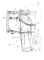
以下、本発明の実施の形態を図面に従って詳述する。図1は動力農機の一例としてトラクタ10を示し、車体の前部にエンジン11が載置されてフード12で被蔽されている。キャビン13の内部にはシート14を装着してあり、ステアリングハンドル15や変速レバー16及び各種操作スイッチ等が設けられている。エンジン11の動力はミッションケース17内に収められたギヤ式変速装置を介して後輪18に伝達されるとともに、ギヤ式変速装置から分岐された動力を前輪動力伝達軸19から前輪20に伝達できるように構成されている。尚、前輪20の駆動部近傍には後述する油圧ポンプ32が設けられており、エンジン11の動力で該油圧ポンプ32が駆動され、油圧モータ33へ作動油が供給される。
【0008】
図2は走行系の動力伝達ブロック図であり、エンジン11の動力は主クラッチ21により入切りされ、ギヤ式変速装置22である前後進切換機23、主変速機24、副変速機25により順次変向或いは変速された後に、差動装置26を経て左右の後輪18へ伝達される。左右の後輪18には夫々ブレーキ装置65,66が設けられており、左右のブレーキペダル(図示せず)により独立してブレーキ操作ができるように構成されている。
【0009】
また、前記ギヤ式変速装置22から動力を分岐し、前輪駆動装置27を経て前輪20を駆動できるように形成されている。前記ギヤ式変速装置22から分岐された動力は、後述するコントローラ70の指令によって4WDクラッチ28で入切りされ、前輪動力伝達軸19に接続した切換装置29へ入力される。そして、この動力は切換装置29から差動装置30を介して前輪20へ伝達される。
【0010】
一方、前輪駆動装置27には、前記ギヤ式変速装置22からの動力で前輪20を駆動する経路とは別に、油圧式変速装置31の動力で前輪20を駆動する経路が設けられている。該油圧式変速装置31は可変式油圧ポンプ32を有し、この油圧ポンプ32によって駆動される油圧モータ33の回転を前記切換装置29へ入力するように構成されている。
【0011】
ここで、前記切換装置29は、ギヤ式変速装置22から分岐された動力の経路と、油圧式変速装置31の動力の経路の何れか一方を選択し、該選択された経路の動力を差動装置30を経て前輪20へ伝達するものである。前記切換装置29には、車体の旋回時に油圧式変速装置31からの動力を優先して伝達する手段が設けられおり、該優先伝達手段としては、例えばワンウェイクラッチを使用する。
【0012】
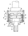
図3はワンウェイクラッチ34を示し、前輪動力伝達軸19に接続されたフルタイム駆動輪35には、台形状の数個のカム36,36…を前面に設けた回転壁37が前後方向中間部から外方へ延設されており、更に、フルタイム駆動輪35を遊転保持するクラッチ軸38の後位置には、多数の小爪39,39…を後面に設けた従動輪40がスプライン等を介して取り付けられる。
【0013】
このフルタイム駆動輪35と従動輪40は互いに独立した状態となっており、この両者間にクラッチ部41が取り付けられている。該クラッチ部41の後面には前記カム36,36…に係合する従動カム42,42…が設けられ、且つ、該クラッチ部41の前面には前記小爪39,39…に噛み合う駆動小爪43,43…が突設されている。
【0014】
44は押圧バネであり、前記クラッチ部41をフルタイム駆動輪35のカム36側へ押圧するように付勢している。また、45は収納ケースであって、フルタイム駆動輪35と一体に回転するとともに、機枠側に当接するブレーキ具46,46…により、その回転に抵抗を与えている。これらフルタイム駆動輪35とクラッチ部41と従動輪40とにより、ワンウェイクラッチ34が構成される。
【0015】
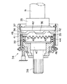
いま、前記ギヤ式変速装置22から分岐された動力が、前輪動力伝達軸19からワンウェイクラッチ34に入力されると、フルタイム駆動輪35が回転して回転壁37のカム36によりクラッチ部41の従動カム42にスラスト力が作用し、クラッチ部41が前方(同図中左方向)へ押圧される。従って、図4に示すように、クラッチ部41の駆動小爪43が従動輪40の小爪39に噛み合って、フルタイム駆動輪35の回転がクラッチ部41を介して従動輪40へ伝わる。斯くして、従動輪40にスプライン嵌合したクラッチ軸38が駆動され、前輪の差動装置30へギヤ式変速装置22からの動力が伝達されて、前輪20が後輪18と同じ周速度で駆動される。
【0016】
ここで、ギヤ式変速装置の動力で前輪20が駆動されている場合は、図4に示すように、ワンウェイクラッチ34が入り状態となってフルタイム駆動輪35と従動輪40が等速で回転するが、このとき、前記油圧式変速装置31からの動力が切換装置29に入力された場合は、油圧モータ33の回転によりクラッチ軸38が駆動される。そして、従動輪40の回転がフルタイム駆動輪35より高くなると、小爪39が駆動小爪43より速く回転してクラッチ部41を高速で回転させ、次に、押圧バネ44の作用によってクラッチ部41全体が後方へ移動し、図3に示したように、従動輪40とクラッチ部41が離間する。
【0017】
従って、ギヤ式変速装置22の動力で前輪20が駆動されている場合であっても、油圧式変速装置31からの動力が切換装置29に入力されたときは、前記ワンウェイクラッチ34が切り状態となって従動輪40が空転する。即ち、油圧式変速装置31からの動力が優先して前輪20へ伝達され、前輪20が油圧モータ33の回転速度に応じた周速度で駆動される。
【0018】
尚、前記優先伝達手段としては、前述したワンウェイクラッチ34のほか、図示は省略するが、ギヤ式変速装置22の動力の経路と油圧式変速装置31の動力の経路に夫々クラッチを設けておき、コントローラ70によっていずれかのクラッチを択一的に入切りするように構成することもできる。
【0019】
図5は制御系のブロック図であり、ポテンショメータ51によりポジションレバーの操作位置を検出し、ポテンショメータ52により変速レバーのシフト位置を検出する。また、ポテンショメータ53によりリフトアームの回動角即ち後部作業機の高さを検出し、ポテンショメータ54,55により夫々左右のブレーキペダルの踏み込み位置を検出する。
【0020】
一方、後進検出スイッチ56は前後進切換機23を後進位置に切り換えたときにオンとなり、クラッチペダルスイッチ57は主クラッチ21を切るためにクラッチペダルを踏み込んだときにオンになる。また、車体の旋回時に油圧式変速装置31の動力により前輪増速旋回制御する場合は、予め制御入切スイッチ58をオンにする。更に、車速を検出する手段として車速センサ59を設ける。車速センサ59の構成としては、例えばドップラ式のセンサにより車体と地面との相対速度を検出して車速を演算するほか、前輪20または後輪18の回転から車速を算出したり、或いは、ギヤ式変速装置22の変速ギヤまたは変速軸等の回転から車速を算出するように構成してもよい。
【0021】
ここで、ステアリングハンドル15の操舵に伴う前輪20の旋回量を検出する手段として前輪切れ角センサ60を設け、エンジン11の回転数を検出する手段としてエンジン回転センサ61を設ける。尚、車体の旋回操作を検出する手段としては、前記前輪切れ角センサ60によって前輪20の操舵角を直接的に検出する他に、ステアリングハンドル15の回転角度やステアリングハンドル15の操作速度を測定したり、パワーステアリング装置の油圧シリンダのピストン伸縮量を検出する方法などもある。
【0022】
また、タイヤのスリップを検出する手段として前輪回転センサ62及び後輪回転センサ63を設け、該前輪回転センサ62及び後輪回転センサ63によって前輪20と後輪18の回転数を検出し、この回転差をコントローラ70へ入力してタイヤのスリップ率を演算する。更に、車体の傾斜を検出する手段として傾斜センサ64を設け、該傾斜センサ64によって車体のローリング角を検出する。
【0023】
前記各検出信号はコントローラ70へ入力され、例えばポテンショメータ51の検出信号に基づいてポジョンレバーの操作位置を判別し、作業機昇降用のリフトシリンダを作動すべく、電磁制御弁の作業機上昇用ソレノイド81または作業機下降用ソレノイド82へ指令信号を出力する。或いは、例えばポテンショメータ54,55の検出信号に基づいて左右のブレーキペダルの踏み込み位置を判別し、その操作力の大小に応じて後輪のブレーキシリンダを作動すべく、電磁制御弁の左ブレーキ用ソレノイド83または右ブレーキ用ソレノイド84へ指令信号を出力する。
【0024】
更に、後述する制御手順に従って、油圧ポンプ32の吐出量を変更するアクチュエータである電動モータ85へ制御信号を出力し、該油圧ポンプ32の吐出量を増減することによって油圧モータ33の回転速度を変化させる。従って、油圧式変速装置31による前輪20の駆動量が変化し、作業モードダイヤル59によって設定した増速比率、若しくは制御目標の増速比率となるように前輪20の周速度を制御する。
【0025】
図6は油圧回路を示し、前記油圧式変速装置31には可変式の油圧ポンプ32が設けられている。該油圧ポンプ32から吐出される作動油は電磁制御弁90によって制御され、前述した制御入切スイッチ58がオフのときは、該電磁制御弁90がノーマル位置(イ)にあって油圧モータ33は駆動されない。そして、制御入切スイッチ58をオンにしたときは、該電磁制御弁90がオフセット位置(ロ)に切り換わり、油圧ポンプ32の吐出油が油圧モータ33へ導出される。
【0026】
ここで、電動モータ85を駆動してトラニオン軸を回転すれば、油圧ポンプ32の斜板若しくは斜軸の角度即ち傾転角が変化し、該油圧ポンプ32の吐出量が増減する。従って、油圧モータ33の流量が変わり、該油圧モータ33の回転速度を任意に調整できる。尚、図示は省略するが可変式の油圧モータを使用し、電動モータによって該油圧モータの傾転角を変化させることにより、油圧モータの流量を変更して回転速度を任意に調整するように構成してもよい。
【0027】
前述したように、たとえ4WDクラッチ28が作動してギヤ式変速装置22から分岐された動力が前輪動力伝達軸19へ伝達されている場合であっても、油圧式変速装置31の動力が切換装置29に入力されたときは、該油圧式変速装置31からの動力が優先して前輪20へ伝達される。
【0028】
尚、同図に於いて符号95a,95bは他の油圧ポンプであり、油圧ポンプ95aから吐出される作動油は電磁制御弁96によって制御され、前記コントローラ70から作業機上昇用ソレノイド81または作業機下降用ソレノイド82へ指令信号が出力されたときに、油圧ポンプ95aの作動油がリフトシリンダ97へ供給されて作業機が昇降する。一方、油圧ポンプ95bから吐出される作動油は、減圧弁98を介してパワーステアリング回路99へ供給され、ステアリングシリンダ100が駆動されて前輪20が回向する。
【0029】
また、減圧弁98から分岐した作動油は、電磁制御弁101,102を介して左右のブレーキシリンダ103,104に導出されるとともに、その他の油圧回路へ供給される。前記コントローラ70から左ブレーキ用ソレノイド83または右ブレーキ用ソレノイド84へ指令信号が出力されたときは、該指令信号の大きさに応じて電磁制御弁101または102が開放し、ブレーキシリンダ103,104が駆動されて左または右のブレーキ装置65,66が作動し、後輪18,18が夫々独立して制動される。
【0030】
ここで、前記油圧式変速装置31の油圧ポンプ32はエンジン11の動力で駆動されるが、前輪増速時には油圧ポンプ32の駆動によってエンジン11への負荷が高くなる。従って、エンジン11がアイドリング等の低回転のときに油圧式変速装置31を作動すると、他の油圧ポンプ95a,95bの吐出量が低下して作動油の供給量が不足し、他の油圧機器が作動不良を起こす虞がある。また、エンジン11への負荷が著しく高くなるとエンストを起こすこともある。
【0031】
このため、前記エンジン回転センサ61の検出値からエンジン回転数を算出し、エンジン11がアイドリング等の低回転になったときは、コントローラ70から前記電動モータ85への制御信号を調整して油圧ポンプの32の吐出量をゼロにすることにより、低回転時の油圧式変速装置31の作動を牽制する。
【0032】
また、エンジン11がアイドリング状態のときに油圧式変速装置31が作動すると、オペレータの意に反して車体が暴走する危険があるが、前述したように、エンジン11のアイドリング時は油圧ポンプの32の吐出量をゼロにすることにより、油圧式変速装置31の不慮作動を防止できる。或いは、コントローラ70の指令によって前記電磁制御弁90をノーマル位置(イ)位置にし、油圧モータ33への作動油の供給を停止することによって油圧モータ33の回転を阻止すれば、前輪20の高速駆動が防止されて安全性を確保できる。
【0033】
ここで、前記油圧式変速装置31の動力によって前輪20を駆動したときの前輪の増速比率(以下、単に「増速比率」という)は、コントローラ70から電動モータ85へ制御信号を出力して油圧ポンプ32の吐出量を調整することによって変更できるが、本発明では、図7の実線A乃至Dで示すように、車体の旋回開始時の車速或いは変速レバーのシフト位置に応じて、増速比率を変更(即ち前輪の駆動量を変更)するように制御する。
【0034】
例えば、前記ギヤ式変速装置22の変速レバーが第1速(低速)位置にシフトされているときは、同図の実線Aで示すように増速比率を比較的低めに設定する。そして、変速レバーが第2速位置にシフトされているときは実線Bで示すように増速比率をやや高く設定し、更に第3速位置或いは第4速位置と変速レバーが高速位置にシフトされているときは、実線CまたはDで示すように夫々増速比率を高く設定する。また、各変速位置に於いては、車体の旋回開始時の車速が高くなるのに伴って、増速比率が大きくなるように制御する。この増速比率の変動ラインは、車体の転倒防止などの安全性を考慮して予め設定される。
【0035】
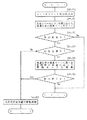
次に、図8のフロチャートに従って、前輪駆動装置27の制御手順について説明する。先ず、各種センサやダイヤルの状態をコントローラ70へ読み込む(ステップ1)。続いて、ポテンショメータ52の検出値から変速レバーのシフト位置を判別し、このシフト位置に応じて、図7に示した増速比率の変動ラインの何れかをセットする。(ステップ2)。
【0036】
いま、前輪の切れ角センサ60の検出値からステアリングハンドル15が所定角度以上に操作されたとき、或いはポテンショメータ54,55の検出値から片ブレーキ操作があったとき、若しくはポテンショメータ51または53の検出値から作業機を上昇させたとき等、車体が旋回を開始したとコントローラ70が判断したときであって(ステップ3)、且つ、後進検出スイッチ56の信号がオフで前後進切換機23が前進位置であるときは(ステップ4)、予め設定された増速比率の変動ラインに基づいて油圧式変速装置31からの動力で前輪20を駆動すべく、コントローラ70から前記電動モータ85へ制御信号を出力する(ステップ5)。
【0037】
従って、変速レバーのシフト位置及び旋回開始時の車速に応じて、油圧式変速装置31の油圧ポンプ32の吐出量が調整され、前輪20の周速度が制御目標の増速比率となるように油圧モータ33の回転数が制御される。前述したように、前輪駆動装置27の切換装置29にギヤ式変速装置22からの動力と油圧式変速装置31からの動力が同時に入力された場合は、油圧式変速装置31からの動力が優先して前輪20へ伝達されるため、変速レバーのシフト位置及び車速に応じて最適の増速比率で前輪20が駆動される。斯くして、車体の旋回時間を短縮することができる。
【0038】
そして、車体の旋回中はこの制御を繰り返し(ステップ6)、車体の旋回が終了して直進状態に復帰したときは、油圧式変速装置31の動力による前輪増速旋回制御を牽制する(ステップ6→7)。然るときは、油圧モータ33の回転が停止して、前記ギヤ式変速装置22から分岐された動力が切換装置29から差動装置30へ伝達され、前輪20は前記ギヤ式変速装置22からの動力により後輪18と同じ周速度で駆動される。
【0039】
ここで、ステップ4に於いて前後進切換機23が後進位置であるときは、たとえ車体の旋回中であっても、油圧式変速装置31の動力による前輪増速旋回制御を牽制する(ステップ4→7)。或いは、設定された増速比率の変動ラインに基づく制御目標値よりも、増速比率を一定値(約1.0〜1.5程度)まで低下させてもよい。斯くして、車体が後進しながら旋回するときは、油圧式変速装置31による前輪20の駆動量が減少若しくは停止されるため、後進時の急旋回がなくなって車体の暴走や転倒などの事故を防止できる。
【0040】
尚、本発明は、本発明の精神を逸脱しない限り種々の改変を為すことができ、そして、本発明が該改変されたものに及ぶことは当然である。
【0041】
【発明の効果】
以上説明したように、本発明ではエンジンの動力をギヤ式変速装置から分岐して前輪へ伝達する経路と、油圧式変速装置からの動力を前輪へ伝達する経路を設け、車体の旋回時には前記油圧式変速装置の動力による前輪の駆動量を旋回開始時の車速に応じて変更する。
【0042】
従って、車速の高低や前後進の状況に応じて最適の増速比率で前輪を駆動でき、前輪のグリップ力を確保しつつ旋回時間を短縮するとともに、前輪の過回転による圃場の荒れを防止できる。
また、エンジン(11)がアイドリングの回転になったとき、コントローラ(70)から上記可変式油圧ポンプ(32)の吐出量を増減する電動モータ(85)への制御信号を調整して該可変式油圧ポンプ(32)の吐出量をゼロにすることによって、低回転時の油圧式変速装置(31)の作動を牽制するように構成したので、油圧式変速装置31が不慮作動することを防止することができる。
【図面の簡単な説明】
図は本発明の実施の形態を示すものである。
【図1】トラクタの側面図。
【図2】走行系の動力伝達ブロック図。
【図3】ワンウェイクラッチが切り状態の縦断面図。
【図4】ワンウェイクラッチが入り状態の縦断面図。
【図5】制御系のブロック図。
【図6】油圧回路図。
【図7】旋回開始時の車速及び変速レバーのシフト位置と増速比率との関係を示すグラフ。
【図8】前輪駆動装置の制御手順を示すフローチャート。
【符号の説明】
10 トラクタ
11 エンジン
18 後輪
20 前輪
22 ギヤ式変速装置
23 前後進切換機
27 前輪駆動装置
29 切換装置
31 油圧式変速装置
32 油圧ポンプ
33 油圧モータ
58 制御入切スイッチ
59 車速センサ
60 前輪切れ角センサ
61 エンジン回転センサ
62 前輪回転センサ
63 後輪回転センサ
70 コントローラ
85 電動モータ[0001]
BACKGROUND OF THE INVENTION
The present invention relates to a front wheel drive device for a power farm machine such as a tractor, a rice transplanter, or a lawn mower, and in particular, the power is branched from a gear transmission of a traveling system and transmitted to the front wheel. The present invention relates to a front wheel drive device for a power agricultural machine configured to transmit power from a transmission to drive a front wheel.
[0002]
[Prior art]
In power farm equipment such as tractors, rice transplanters, lawn mowers, etc., the engine power is transmitted to the rear wheels via a gear transmission, and the front wheels can be driven by branching the power from the gear transmission. The configuration is known. In such a configuration, the power transmission to the front wheels is turned on and off by the 4WD clutch to switch the four-wheel drive.
[0003]
In addition to the gear-type transmission, a transmission gear is provided on the power transmission shaft to the front wheels. When the vehicle body turns, the rotation speed of the front wheels is increased by the transmission gear so that the peripheral speed of the front wheels is higher than that of the rear wheels. There is also known a power farm machine that performs so-called front-wheel-accelerated turning control that shortens the turning time.
[0004]
[Problems to be solved by the invention]
In the conventional front wheel acceleration turning control, the front wheels are driven at high speed rotation at a speed increase ratio (for example, twice that of the rear wheels) set in advance with respect to the peripheral speed of the rear wheels when the vehicle is turning. Here, since the grip force of the front wheels varies depending on the vehicle speed at the time of turning, if the speed increase ratio can be increased or decreased according to the vehicle speed, the turn time of the vehicle body can be shortened or the field of the field due to over rotation of the front wheels can be reduced. Roughness can be prevented. Further, when the vehicle body turns while moving backward, if the front wheels are driven at a high speed, the vehicle body turns suddenly, which is dangerous. However, in the conventional front wheel drive device, the speed increasing ratio is constant unless the transmission gear combination is changed, and the peripheral speed of the front wheels cannot be increased or decreased.
[0005]
Therefore, the technology to be solved in order to shorten the turning time by driving the front wheels at high speed when turning the vehicle body, and to change the speed increase ratio of the front wheels according to the level of the vehicle speed and the forward / backward traveling situation The present invention aims to solve this problem.
[0006]
[Means for Solving the Problems]
The present invention has been proposed to achieve the above object, and transmits the power of the engine (11) to the rear wheels (18) via the gear transmission (22). 22) A power farm machine having a path for branching power from 22) to drive the front wheels (20), and provided with means for detecting a turning operation of the vehicle body and means (59) for detecting the vehicle speed. In addition to the path for driving the front wheels (20) from the device (22), a path for transmitting the power of the hydraulic transmission (31) having the variable hydraulic pump (32) to drive the front wheels (20) is provided. A switching device (29) for switching the driving of the front wheels (20) from the path of the gear type transmission (22) to the path of the hydraulic transmission (31) at the time of turning of the vehicle body is provided, and the vehicle speed at the start of turning of the vehicle body Depending on the hydraulic transmission (31 In front wheel drive configuration the power agricultural equipment so as to change the driving amount of the (20) (27) by,
It calculates the engine speed from the detected value of the engine the engine speed sensor provided as a means for detecting the rotational speed of (11) (61), when the engine (11) becomes rotation of idling, the controller ( 70) to adjust the control signal to the electric motor (85) that increases or decreases the discharge amount of the variable hydraulic pump (32) to reduce the discharge amount of the variable hydraulic pump (32) to zero. Provided is a front wheel drive device for a power agricultural machine configured to check the operation of the hydraulic transmission (31) at the time.
[0007]
DETAILED DESCRIPTION OF THE INVENTION
Hereinafter, embodiments of the present invention will be described in detail with reference to the drawings. FIG. 1 shows a
[0008]
FIG. 2 is a power transmission block diagram of the traveling system. The power of the
[0009]
Further, the power is branched from the
[0010]
On the other hand, the front
[0011]
Here, the
[0012]
FIG. 3 shows a one-
[0013]
The full-time driving
[0014]
[0015]
Now, when the power branched from the
[0016]
Here, when the
[0017]
Accordingly, even when the
[0018]
As the priority transmission means, in addition to the one-way clutch 34 described above, although not shown, a clutch is provided in each of the power path of the
[0019]
FIG. 5 is a block diagram of the control system. The potentiometer 51 detects the position lever operating position, and the potentiometer 52 detects the shift lever shift position. Further, the rotation angle of the lift arm, that is, the height of the rear working machine is detected by the potentiometer 53, and the depression positions of the left and right brake pedals are detected by the potentiometers 54 and 55, respectively.
[0020]
On the other hand, the reverse detection switch 56 is turned on when the forward /
[0021]
Here, a front wheel break angle sensor 60 is provided as means for detecting the turning amount of the
[0022]
Further, a front wheel rotation sensor 62 and a rear wheel rotation sensor 63 are provided as means for detecting tire slip, and the front wheel rotation sensor 62 and the rear wheel rotation sensor 63 detect the rotational speeds of the
[0023]
Each of the detection signals is input to the
[0024]
Further, according to the control procedure described later, a control signal is output to the
[0025]
FIG. 6 shows a hydraulic circuit, and the
[0026]
Here, when the
[0027]
As described above, even if the
[0028]
In the figure,
[0029]
The hydraulic oil branched from the
[0030]
Here, the
[0031]
For this reason, the engine speed is calculated from the detection value of the engine rotation sensor 61, and when the
[0032]
Further, if the
[0033]
Here, the speed increase ratio of the front wheels when the
[0034]
For example, when the shift lever of the gear-
[0035]
Next, the control procedure of the front
[0036]
Now, when the
[0037]
Accordingly, the discharge amount of the
[0038]
Then, this control is repeated while the vehicle body is turning (step 6). When the vehicle body turns and returns to the straight-ahead state, the front wheel acceleration turning control by the power of the
[0039]
Here, when the forward /
[0040]
It should be noted that the present invention can be variously modified without departing from the spirit of the present invention, and the present invention naturally extends to the modified ones.
[0041]
【The invention's effect】
As described above, according to the present invention, a path for branching engine power from the gear transmission to the front wheels and a path for transmitting power from the hydraulic transmission to the front wheels are provided. The driving amount of the front wheels by the power of the transmission is changed according to the vehicle speed at the start of turning.
[0042]
Therefore, it is possible to drive the front wheels at an optimal speed increase ratio according to the level of the vehicle speed and the forward / backward travel, shorten the turning time while ensuring the grip force of the front wheels, and prevent the field from being rough due to over rotation of the front wheels .
Further, when the engine (11) becomes rotation of idling, by adjusting the control signal to the controller electric motor (85) from (70) to increase or decrease the discharge amount of the variable hydraulic pump (32) the Since the discharge amount of the variable hydraulic pump (32) is set to zero so that the operation of the hydraulic transmission (31) at the time of low rotation is controlled, the
[Brief description of the drawings]
The figure shows an embodiment of the present invention.
FIG. 1 is a side view of a tractor.
FIG. 2 is a power transmission block diagram of a traveling system.
FIG. 3 is a longitudinal sectional view showing a state in which a one-way clutch is disengaged.
FIG. 4 is a longitudinal sectional view showing a state in which a one-way clutch is engaged.
FIG. 5 is a block diagram of a control system.
FIG. 6 is a hydraulic circuit diagram.
FIG. 7 is a graph showing the relationship between the vehicle speed at the start of turning, the shift position of the shift lever, and the speed increase ratio.
FIG. 8 is a flowchart showing a control procedure of the front wheel drive device.
[Explanation of symbols]
DESCRIPTION OF
Claims (1)
上記エンジン(11)の回転数を検出する手段として設けられたエンジン回転センサ(61)の検出値からエンジン回転数を算出し、エンジン(11)がアイドリングの回転になったとき、コントローラ(70)から上記可変式油圧ポンプ(32)の吐出量を増減する電動モータ(85)への制御信号を調整して該可変式油圧ポンプ(32)の吐出量をゼロにすることによって、低回転時の油圧式変速装置(31)の作動を牽制するように構成して成ることを特徴とする動力農機の前輪駆動装置。The power of the engine (11) is transmitted to the rear wheels (18) via the gear transmission (22), and a path for branching the power from the gear transmission (22) to drive the front wheels (20) is provided. A power farm machine provided with means for detecting a turning operation of the vehicle body and means (59) for detecting the vehicle speed, separately from the path for driving the front wheels (20) from the gear transmission (22), A path for transmitting the power of a hydraulic transmission (31) having a variable hydraulic pump (32) to drive the front wheels (20) is provided, and the front wheels (20) are driven when the vehicle body is turning. 22) and a switching device (29) for switching from the route of the hydraulic transmission (31) to the route of the hydraulic transmission (31), and the front wheel (20) by the hydraulic transmission (31) according to the vehicle speed at the start of turning of the vehicle body. Dynamics configured to change the drive amount In front wheel drive system of agricultural machinery (27),
It calculates the engine speed from the detected value of the engine the engine speed sensor provided as a means for detecting the rotational speed of (11) (61), when the engine (11) becomes rotation of idling, the controller ( 70) to adjust the control signal to the electric motor (85) that increases or decreases the discharge amount of the variable hydraulic pump (32) to reduce the discharge amount of the variable hydraulic pump (32) to zero. A front-wheel drive device for a power agricultural machine, characterized in that the operation of the hydraulic transmission (31) during operation is restrained.
Priority Applications (1)
| Application Number | Priority Date | Filing Date | Title |
|---|---|---|---|
| JP36095097A JP4135200B2 (en) | 1997-12-26 | 1997-12-26 | Front-wheel drive device for power farm equipment |
Applications Claiming Priority (1)
| Application Number | Priority Date | Filing Date | Title |
|---|---|---|---|
| JP36095097A JP4135200B2 (en) | 1997-12-26 | 1997-12-26 | Front-wheel drive device for power farm equipment |
Publications (2)
| Publication Number | Publication Date |
|---|---|
| JPH11189057A JPH11189057A (en) | 1999-07-13 |
| JP4135200B2 true JP4135200B2 (en) | 2008-08-20 |
Family
ID=18471586
Family Applications (1)
| Application Number | Title | Priority Date | Filing Date |
|---|---|---|---|
| JP36095097A Expired - Lifetime JP4135200B2 (en) | 1997-12-26 | 1997-12-26 | Front-wheel drive device for power farm equipment |
Country Status (1)
| Country | Link |
|---|---|
| JP (1) | JP4135200B2 (en) |
Families Citing this family (2)
| Publication number | Priority date | Publication date | Assignee | Title |
|---|---|---|---|---|
| JP4684790B2 (en) * | 2005-07-29 | 2011-05-18 | 富士重工業株式会社 | Torque distribution device |
| JP4923126B2 (en) * | 2010-04-09 | 2012-04-25 | 本田技研工業株式会社 | Control method for four-wheel drive vehicle |
-
1997
- 1997-12-26 JP JP36095097A patent/JP4135200B2/en not_active Expired - Lifetime
Also Published As
| Publication number | Publication date |
|---|---|
| JPH11189057A (en) | 1999-07-13 |
Similar Documents
| Publication | Publication Date | Title |
|---|---|---|
| US9283951B2 (en) | Speed change system for work vehicle | |
| US7540825B2 (en) | Drive system of a working vehicle | |
| KR101375957B1 (en) | Transmission switch-over apparatus and speed control apparatus for working vehicle | |
| JP2011149496A (en) | Vehicle speed control structure of work vehicle | |
| JP4300723B2 (en) | Tractor | |
| JP3950273B2 (en) | Switch operation of work vehicle | |
| JP4135200B2 (en) | Front-wheel drive device for power farm equipment | |
| US6112842A (en) | Working vehicle | |
| JP5745227B2 (en) | Shifting operation structure of work vehicle | |
| JP3876498B2 (en) | Turning control device for work vehicle | |
| JP3982037B2 (en) | Front-wheel drive device for power farm equipment | |
| JP4796432B2 (en) | Work vehicle travel stop control device | |
| JP2021107689A (en) | Work vehicle | |
| JP3982036B2 (en) | Front-wheel drive device for power farm equipment | |
| JP3982035B2 (en) | Front-wheel drive device for power farm equipment | |
| JP2003185006A (en) | Transmission control device of working vehicle | |
| JP5261407B2 (en) | Information display structure of work vehicle | |
| JP3731282B2 (en) | Steering control device for work vehicle | |
| CA2687379A1 (en) | Momentary activation of mechanical front wheel drive | |
| JP3134462B2 (en) | Travel turning control device of combine | |
| JP3516723B2 (en) | Paddy working machine | |
| JP3903551B2 (en) | Steering control device for work vehicle | |
| JP3622217B2 (en) | 4WD lock control device for tractor | |
| JP2021107165A (en) | Work vehicle | |
| JP2021107690A (en) | Work vehicle |
Legal Events
| Date | Code | Title | Description |
|---|---|---|---|
| A621 | Written request for application examination |
Free format text: JAPANESE INTERMEDIATE CODE: A621 Effective date: 20040304 |
|
| A977 | Report on retrieval |
Free format text: JAPANESE INTERMEDIATE CODE: A971007 Effective date: 20061026 |
|
| A131 | Notification of reasons for refusal |
Free format text: JAPANESE INTERMEDIATE CODE: A131 Effective date: 20061205 |
|
| A521 | Written amendment |
Free format text: JAPANESE INTERMEDIATE CODE: A523 Effective date: 20070122 |
|
| A131 | Notification of reasons for refusal |
Free format text: JAPANESE INTERMEDIATE CODE: A131 Effective date: 20070612 |
|
| A521 | Written amendment |
Free format text: JAPANESE INTERMEDIATE CODE: A523 Effective date: 20070720 |
|
| TRDD | Decision of grant or rejection written | ||
| A01 | Written decision to grant a patent or to grant a registration (utility model) |
Free format text: JAPANESE INTERMEDIATE CODE: A01 Effective date: 20080513 |
|
| A01 | Written decision to grant a patent or to grant a registration (utility model) |
Free format text: JAPANESE INTERMEDIATE CODE: A01 |
|
| A61 | First payment of annual fees (during grant procedure) |
Free format text: JAPANESE INTERMEDIATE CODE: A61 Effective date: 20080526 |
|
| R150 | Certificate of patent or registration of utility model |
Free format text: JAPANESE INTERMEDIATE CODE: R150 |
|
| FPAY | Renewal fee payment (event date is renewal date of database) |
Free format text: PAYMENT UNTIL: 20110613 Year of fee payment: 3 |
|
| FPAY | Renewal fee payment (event date is renewal date of database) |
Free format text: PAYMENT UNTIL: 20110613 Year of fee payment: 3 |
|
| FPAY | Renewal fee payment (event date is renewal date of database) |
Free format text: PAYMENT UNTIL: 20140613 Year of fee payment: 6 |
|
| EXPY | Cancellation because of completion of term |