JP4134897B2 - Robot control method, control apparatus, and robot system - Google Patents
Robot control method, control apparatus, and robot system Download PDFInfo
- Publication number
- JP4134897B2 JP4134897B2 JP2003418375A JP2003418375A JP4134897B2 JP 4134897 B2 JP4134897 B2 JP 4134897B2 JP 2003418375 A JP2003418375 A JP 2003418375A JP 2003418375 A JP2003418375 A JP 2003418375A JP 4134897 B2 JP4134897 B2 JP 4134897B2
- Authority
- JP
- Japan
- Prior art keywords
- control point
- robot
- control
- cube
- interference
- Prior art date
- Legal status (The legal status is an assumption and is not a legal conclusion. Google has not performed a legal analysis and makes no representation as to the accuracy of the status listed.)
- Expired - Fee Related
Links
Images


Description
本発明は、産業用ロボットを用いて作業を行う場合、当該産業用ロボットと他の外部機器(または、他のロボット)との干渉回避方法に関するものである。 The present invention relates to a method for avoiding interference between an industrial robot and other external devices (or other robots) when working with the industrial robot.
産業用ロボットと他の外部機器(あるいは他の産業用ロボット)と協同して作業を行う場合、当該産業用ロボットと前記外部機器との干渉を回避するため、一定の干渉領域(一般に立方体で領域を定義するので、キューブと呼ばれる)を設定し、前記干渉領域内に当該産業用ロボットの制御点が存在する時は、前記外部機器の前記干渉領域への侵入を禁止し、逆に前記外部機器が前記干渉領域にある時は、当該産業用ロボットの前記干渉用領域への侵入を禁止していた(例えば、特許文献1)。
しかしながら、従来の干渉回避方法では、産業用ロボットの制御点の位置として、指令位置を用いて、前記制御点が前記制御領域の内部にあるか否かを判断していた。しかし、指令位置と実際の位置(ロボットの各関節軸のエンコーダからフィードバックされる回転角度から得られる位置なので、フィードバック位置と呼ばれる)は、0.3秒以上のタイムラグがあり、1000mm/sで制御点が移動している場合には、速度を乗じたものを位置ループゲイン(一般的には10〜15)で除した値が指令位置とフィードバック位置の間にずれとして生じるので、70〜100mm程度のずれが生じる。
そのため、実際には既に前記制御点が前記干渉領域に侵入しているにも関わらず、侵入していないと誤認して、産業用ロボットと外部機器の干渉が発生するという問題があった。また、この問題を解決するために、前記干渉領域を大きく設定すると、前記干渉領域から離脱するための移動距離が大きくなるので、無駄時間が生じ、能率が低下するという問題があった。
本発明は、これらの問題に鑑みてなされたものであり、最小限の干渉領域で、産業用ロボットと外部機器等の干渉を確実に回避するとともに、干渉回避のために生じる無駄時間を最小に留め、作業能率の高い産業用ロボットの干渉回避方法を提供することを目的とするものである。
However, in the conventional interference avoidance method, the command position is used as the position of the control point of the industrial robot to determine whether or not the control point is inside the control region. However, the command position and the actual position (referred to as the feedback position because it is a position obtained from the rotation angle fed back from the encoder of each joint axis of the robot) has a time lag of 0.3 seconds or more and is controlled at 1000 mm / s. When the point is moving, a value obtained by dividing the product of the speed by the position loop gain (generally 10 to 15) is generated as a deviation between the command position and the feedback position, so about 70 to 100 mm. Deviation occurs.
Therefore, in practice, not already though the control points are invading the interference region, and misidentified as not invade, interfere of an industrial robot and an external device is disadvantageously generated. Further, in order to solve this problem, if the interference area is set to be large, the moving distance for moving away from the interference area becomes large, so that there is a problem that dead time occurs and efficiency is lowered.
The present invention has been made in view of these problems, a minimum with a minimum of interference region, in together when reliably avoid interference such as an industrial robot and an external device, the dead time caused due to interference avoidance Therefore, an object of the present invention is to provide an interference avoidance method for an industrial robot with high work efficiency.
上記問題を解決するために、本発明は次のように構成したのである。
請求項1に記載の発明は、位置検出手段が出力する位置情報をフィードバックしてロボットの制御点(2)の現在位置を求め、前記制御点(2)の現在位置に応じて前記制御点(2)の位置指令を出力することにより、前記制御点(2)を所望の位置に制御するフィードバック制御手段と、予め設定された干渉領域(4)にロボットの制御点(2)が存在することを判別して、外部機器または他のロボット(3)の前記干渉領域への侵入を禁止する禁止手段と、を備えたロボットの制御装置において、前記禁止手段は、前記制御点(2)が前記干渉領域(4)に侵入するときは、前記制御点(2)の指令位置が前記干渉領域(4)内に入った時をもって「侵入」と判断し、前記制御点(2)が前記干渉領域(4)を離脱するときは、前記制御点(2)の現在位置が前記干渉領域(4)を出た時をもって「離脱」と判断することを特徴とするものである。
また、請求項2に記載の発明は、位置検出手段が出力する位置情報をフィードバックしてロボットの制御点(2)の現在位置を求め、前記制御点(2)の現在位置に応じて前記制御点(2)の位置指令を出力することにより、前記制御点(2)を所望の位置に制御するフィードバック制御手段と、予め設定された干渉領域(4)にロボットの制御点(2)が存在することを判別して、外部機器または他のロボット(3)の前記干渉領域への侵入を禁止する手段と、を備えたロボットの制御装置において、前記制御点(2)が前記干渉領域(4)に侵入するときは、前記制御点(2)の指令位置が前記干渉領域(4)内に入った時をもって「侵入」と判断し、前記制御点(2)が前記干渉領域(4)を離脱するときは、前記制御点(2)の現在位置が前記干渉領域(4)を出た時をもって「離脱」と判断する判断手段を備えたことを特徴とするものである。
また、請求項3に記載の発明は、請求項2記載のロボットの制御装置と、前記制御装置によって制御されるロボットと、を備えたことを特徴とするものである。
In order to solve the above problem, the present invention is configured as follows.
According to the first aspect of the present invention , the current position of the control point (2) of the robot is obtained by feeding back the position information output by the position detecting means, and the control point (2) is determined according to the current position of the control point (2). by outputting a position command 2), and feedback control means and said control points (2) is controlled to a desired position, the control point of the robot (2) present in the pre-set interference region (4) it was determined, in the control apparatus of a robot and a prohibiting means for prohibiting intrusion into the interference region of the external device or another robot (3), said inhibiting means, said control point (2) There when entering the interference region (4), with when the command position of the control point (2) enters the interference region (4) in determining the "penetration", the control point (2) of the when leaving the interference area (4), the control (2) the current position of have when leaving the interference area (4) is characterized in that it is determined that "leaving".
According to a second aspect of the present invention, the current position of the control point (2) of the robot is obtained by feeding back the position information output by the position detection means, and the control is performed according to the current position of the control point (2). by outputting a position command of point (2), and feedback control means and said control points (2) is controlled to a desired position, the control point of the robot to a preset interference region (4) (2) determine the present, the interference means for prohibiting the entry into the area, the control apparatus of a robot wherein the control point (2) of the interference region of the external device or another robot (3) (4) when entering the have when the command position of the control point (2) enters the interference region (4) in determining the "penetration", the control point (2) of the interference region (4 ) when leaving the the current of the control point (2) Have when location exits said interference region (4) is characterized in that it comprises a determining means for determining a "leaving".
The invention according to
本発明によれば、干渉領域に侵入するときは制御点の指令位置で「侵入」を判断し、干渉領域から離脱するときは制御点のフィードバック位置で「離脱」を判断するので、指令位置と現実の位置にずれがあっても、確実かつ安全に干渉を回避できる効果がある。また、干渉領域の大きさを小さく出来るので、干渉回避のために生じる無駄時間を最小に留め、作業能率を高める効果がある。 According to the present invention, when entering the interference area, “ intrusion ” is determined at the command position of the control point, and when leaving from the interference area, “separation” is determined at the feedback position of the control point. Even if there is a deviation in the actual position, there is an effect that interference can be avoided reliably and safely. In addition, since the size of the interference area can be reduced, there is an effect of minimizing dead time for avoiding interference and increasing work efficiency.
以下、本発明の具体的実施例を図に基づいて説明する。 Hereinafter, specific embodiments of the present invention will be described with reference to the drawings.
図1は、本発明の実施例を示す産業用ロボットと外部機器の協同作業の説明図である。図において、1はいわゆる垂直多関節型の産業用ロボットであり、2は産業用ロボット1の制御点である。制御点2は産業用ロボット1の先端に設定された基準点であり、図示しないロボット制御装置は制御点2を所定の位置に位置決めし、所定の軌跡をトレースし、あるいは所定の速度で移動するように制御する。3は外部機器であり、図の左右方向に移動位置決めして所定の作業を行う機器である。4はキューブである。キューブ4は、産業用ロボット1と外部機器3の間に設定した仮想の立方体であり、この立方体の内部に産業用ロボット1と外部機器3が同時に侵入すると、両者が干渉する恐れのある領域つまり干渉領域である。
FIG. 1 is an explanatory diagram of cooperative work between an industrial robot and an external device according to an embodiment of the present invention. In the figure, 1 is a so-called vertical articulated industrial robot, and 2 is a control point of the industrial robot 1. The
図1(a)の状態にあっては、産業用ロボット1および外部機器3はいずれもキューブ4の外にあるので、互いに干渉しない。図1(b)に示すように、産業用ロボット1の制御点2がキューブ4の中に侵入すると、外部機器3がキューブ4の中に侵入することが禁止される。また、図1(c)に示すように、産業用ロボット1の制御点2がキューブ4のから離脱すると、外部機器3がキューブ4の中に侵入することが許可されるので、外部機器3は右に移動してキューブ4の中に侵入する。また、外部機器3がキューブ4の中にある間は、産業用ロボット1の制御点2はキューブ4の中に侵入することを禁止される。
In the state of FIG. 1A, the industrial robot 1 and the
図2は本発明の実施例を示す産業用ロボットの制御系のブロック図である。図において、5は産業用ロボットの作業プログラム6を作成編集するマンマシンインターフェイス(MMI)である。マンマシンインターフェイス15で作成された作業プログラム6はインタプリタ7に読み込まれる。インタプリタ7にて読み取った作業プログラム6の中の動作命令に基づいて、補間演算部8にて補間処理・座標変換を行い、各軸移動指令量を算出する。そして、キューブチェック処理部9にてキューブ内外のチェックを行い、各軸を駆動するサーボドライバ10に指令を送る。
FIG. 2 is a block diagram of an industrial robot control system showing an embodiment of the present invention. In the figure, 5 is a man-machine interface (MMI) for creating and editing an industrial
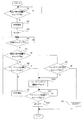
図3は本発明の実施例を示すキューブチェック処理のアルゴリズムを示すフローチャートであり、図1(a)の状態から図1(b)の状態へ動作する(初期状態から産業用ロボット1がキューブ4内へ動作する)時にキューブチェック処理部9が移動指令の分配周期ごとに実施する処理として本アルゴリズムを実施する。但し、実装に当たっては各周期毎に呼び出されるため時間計測処理状態を実現するための考慮が必要となる。以下、図に付したステップ番号を引用して説明する。
(ステップS1)まず、産業用ロボット1の作業プログラム6をインタプリタ7にて読み、読み取った作業プログラムの移動指令より補間演算部8にて移動指令量を算出する。そして移動位置指令が出されると、キューブチェック処理部9ではまず、産業用ロボット1の現在の指令位置がキューブ4内であるかどうかをチェックする。キューブ4内ではないと判断されたとき、キューブ内に入るまでキューブ内4に入ったかどうかのチェックを行う。
(ステップS2)ステップS1にて、キューブ4内であると判断されたとき計時を開始する(例えば0.5s)。
(ステップS3)産業用ロボット1の制御位置がキューブ内に入ったため、「侵入」と判断して、外部機器3に対して動作禁止を指令する信号をオンとして、外部機器3の動作を禁止する。
(ステップS4)指定された時間になるまで、計時を行う。
(ステップS5)ステップS4にて計時タイムアップと判断されたとき、産業用ロボット1の現在の指令位置がキューブ4内であるかどうかをチェックする。
(ステップS6)ステップS5にてキューブ4内であると判断されたとき、産業用ロボット1のフィードバック位置がキューブ4内であるかチェックする。
(ステップS7)ステップS6にて産業用ロボット1のフィードバック位置がキューブ4に入っていないと判断されたとき、もう一度計時を開始する。
FIG. 3 is a flowchart showing an algorithm of a cube check process according to the embodiment of the present invention. The cube check process operates from the state of FIG. 1A to the state of FIG. This algorithm is executed as a process that the cube
(Step S1) First, the
(Step S2) When it is determined in Step S1 that it is in the cube 4, time counting is started (for example, 0.5 s).
(Step S3) Since the control position of the industrial robot 1 has entered the cube, it is determined as “ intrusion”, and the signal for commanding the operation prohibition to the
(Step S4) Time is measured until the designated time is reached.
(Step S5) When it is determined in step S4 that the time is up, it is checked whether or not the current command position of the industrial robot 1 is within the cube 4.
(Step S6) When it is determined in step S5 that it is in the cube 4, it is checked whether the feedback position of the industrial robot 1 is in the cube 4.
(Step S7) When it is determined in Step S6 that the feedback position of the industrial robot 1 is not in the cube 4, the time measurement is started again.
(ステップS8)ステップS5にてキューブ4内に産業用ロボット1の指令位置が入っていないと判断されたとき、産業用ロボット1の指令位置は1度キューブ4内に侵入しているため、フィードバック位置がキューブ4内であるかどうかチェックする。この場合は計時している短い間に、産業用ロボット1の指令位置がキューブ4に侵入し離脱しているので、産業用ロボット1がキューブ4をかすめた状態となる。
(ステップS9)ステップS8にてフィードバック位置がキューブ4内に入っていないと判断されたとき、指令位置、フィードバック位置の両方がキューブ4に入っていないため「離脱」と判断され、外部機器3に対して動作禁止を指令する信号をオフとして、外部機器3の動作を許可する。
(ステップS10)ステップS6、ステップS8にて産業用ロボット1のフィードバック位置がキューブ4内に入っていると判断されたとき、産業用ロボット1のキューブ4からの離脱をフィードバック位置にてチェックする。
(ステップS11)そして、産業用ロボット1の制御点がキューブ4から出たかどうかを前記フィードバック位置を基準に判断する。
(ステップS12)ステップS11にてキューブ4から産業用ロボット1の制御点のフィードバック位置が出たと判断されたときは「離脱」と判断され、外部機器3に対して動作禁止を指令する信号をオフとして、外部機器3の動作を許可する。
以上の処理によって、産業用ロボット1の制御点がキューブ4の中にないときは指令位置にてチェックし(ステップS1)、キューブ4の中にあるときはフィードバック位置にてチェックする(ステップS6、S8、S10)。
(Step S8) when it is determined that the command position of the industrial robot 1 is not in the cube 4 in step S5, since the command position of the industrial robot 1 is intruded into the once cube 4, Feedback Check if the position is in the cube 4. In this case, since the command position of the industrial robot 1 enters and leaves the cube 4 during a short period of time keeping, the industrial robot 1 is in a state of grazing the cube 4.
(Step S9) When it is determined in Step S8 that the feedback position is not in the cube 4, it is determined that the command position and the feedback position are not in the cube 4, so that it is “leaving”. On the other hand, the operation command of the
(Step S10) When it is determined in Steps S6 and S8 that the feedback position of the industrial robot 1 is in the cube 4, the separation of the industrial robot 1 from the cube 4 is checked at the feedback position.
(Step S11) Then, whether or not the control point of the industrial robot 1 has come out of the cube 4 is determined based on the feedback position.
(Step S12) When it is determined in Step S11 that the feedback position of the control point of the industrial robot 1 has come out of the cube 4, it is determined as “leaving” and the signal for instructing the
By the above processing, when the control point of the industrial robot 1 is not in the cube 4, it is checked at the command position (step S1), and when it is in the cube 4, it is checked at the feedback position (step S6, S8, S10).
本発明は、産業用ロボットを用いて作業を行う場合の当該産業用ロボットと他の外部機器(または、他のロボット)との干渉回避方法として有用である。 INDUSTRIAL APPLICABILITY The present invention is useful as a method for avoiding interference between an industrial robot and other external devices (or other robots) when working using the industrial robot.
1 産業用ロボット
2 制御点
3 外部機器
4 キューブ
5 マンマシンインターフェイス
6 作業プログラム
7 インタプリタ
8 補間演算部
9 キューブチェック処理部
10 サーボドライバ
DESCRIPTION OF SYMBOLS 1
Claims (3)
予め設定された干渉領域(4)にロボットの制御点(2)が存在することを判別して、外部機器または他のロボット(3)の前記干渉領域への侵入を禁止する禁止手段と、を備えたロボットの制御装置において、
前記禁止手段は、前記制御点(2)が前記干渉領域(4)に侵入するときは、前記制御点(2)の指令位置が前記干渉領域(4)内に入った時をもって「侵入」と判断し、
前記制御点(2)が前記干渉領域(4)を離脱するときは、前記制御点(2)の現在位置が前記干渉領域(4)を出た時をもって「離脱」と判断することを特徴とするロボットの制御方法。 Feedback of position information output from the position detection means to obtain the current position of the control point (2) of the robot, and output a position command of the control point (2) according to the current position of the control point (2) Feedback control means for controlling the control point (2) to a desired position by:
Preset interference region (4) in the B control point Bot (2) to determine the presence of, and inhibiting means for inhibiting the entry into the interference region of the external device or another robot (3) In a robot control device equipped with
It said inhibiting means, when said control points (2) penetrates into the interference region (4), with when the command position of the control point (2) enters the interference region (4) in the "penetration" Judgment
When the control point (2) leaves the interference area (4) , it is determined that the current position of the control point (2 ) has left the interference area (4). method of controlling the to Carlo bot.
予め設定された干渉領域(4)にロボットの制御点(2)が存在することを判別して、外部機器または他のロボット(3)の前記干渉領域への侵入を禁止する手段と、を備えたロボットの制御装置において、
前記制御点(2)が前記干渉領域(4)に侵入するときは、前記制御点(2)の指令位置が前記干渉領域(4)内に入った時をもって「侵入」と判断し、
前記制御点(2)が前記干渉領域(4)を離脱するときは、前記制御点(2)の現在位置が前記干渉領域(4)を出た時をもって「離脱」と判断する判断手段を備えたことを特徴とするロボットの制御装置。 Feedback of position information output from the position detection means to obtain the current position of the control point (2) of the robot, and output a position command of the control point (2) according to the current position of the control point (2) Feedback control means for controlling the control point (2) to a desired position by:
It was determined that preset interference region (4) in the B control points of bots (2) present, a means for inhibiting entry into said interference region of the external device or another robot (3), In a robot control device equipped with
When the control point (2) penetrates into the interference region (4), with when the command position of the control point (2) enters the interference region (4) in determining that "intrusion"
When the control point (2) leaves the interference area (4) , the control point (2) includes a determination unit that determines that the current position of the control point (2) leaves the interference area (4). controller features and to Carlo bot that was.
前記制御装置によって制御されるロボットと、を備えたことを特徴とするロボットシステム。 A control device for robot according to claim 2,
Robot system is characterized in that and a Carlo bot is controlled by the control device.
Priority Applications (1)
| Application Number | Priority Date | Filing Date | Title |
|---|---|---|---|
| JP2003418375A JP4134897B2 (en) | 2003-12-16 | 2003-12-16 | Robot control method, control apparatus, and robot system |
Applications Claiming Priority (1)
| Application Number | Priority Date | Filing Date | Title |
|---|---|---|---|
| JP2003418375A JP4134897B2 (en) | 2003-12-16 | 2003-12-16 | Robot control method, control apparatus, and robot system |
Publications (3)
| Publication Number | Publication Date |
|---|---|
| JP2005177875A JP2005177875A (en) | 2005-07-07 |
| JP2005177875A5 JP2005177875A5 (en) | 2006-09-21 |
| JP4134897B2 true JP4134897B2 (en) | 2008-08-20 |
Family
ID=34780601
Family Applications (1)
| Application Number | Title | Priority Date | Filing Date |
|---|---|---|---|
| JP2003418375A Expired - Fee Related JP4134897B2 (en) | 2003-12-16 | 2003-12-16 | Robot control method, control apparatus, and robot system |
Country Status (1)
| Country | Link |
|---|---|
| JP (1) | JP4134897B2 (en) |
-
2003
- 2003-12-16 JP JP2003418375A patent/JP4134897B2/en not_active Expired - Fee Related
Also Published As
| Publication number | Publication date |
|---|---|
| JP2005177875A (en) | 2005-07-07 |
Similar Documents
| Publication | Publication Date | Title |
|---|---|---|
| US10695909B2 (en) | Robot system and robot control method | |
| JP6351900B2 (en) | Robot controller | |
| JP4736607B2 (en) | Robot controller | |
| JP5768828B2 (en) | Robot system and control method of robot system | |
| JPH103308A (en) | Interference avoiding method for industrial robot | |
| JP2005293098A (en) | Robot teaching apparatus | |
| US9895769B2 (en) | Laser processing device having function for avoiding interference at the time of nozzle approach | |
| JP4461030B2 (en) | Numerical control apparatus and numerical control method | |
| JP2016159367A (en) | Robot control device for automatically switching operation mode of robot | |
| WO2012101789A1 (en) | Numerical control device | |
| JP2018062026A (en) | Robot control device with function for restricting speed and acceleration of robot | |
| JP6478771B2 (en) | Avoidance trajectory generation apparatus and avoidance trajectory generation method for industrial robot | |
| JPH11347983A (en) | Manipulator action limiting device | |
| JP6490031B2 (en) | Robot control apparatus and control method | |
| JP4134897B2 (en) | Robot control method, control apparatus, and robot system | |
| JP2010231737A (en) | Numerical control device having interference check function | |
| JP2020003958A (en) | Numerical control device | |
| JP7384602B2 (en) | robot control device | |
| JP2000052076A (en) | Laser processing device and processing head driving method | |
| JPH0337701A (en) | Method and device for robot control | |
| JP2008148449A (en) | Motor position control method | |
| JP3868579B2 (en) | Laser processing method and apparatus | |
| JP2007249671A (en) | Method for preventing collision in machine tool | |
| JP7028083B2 (en) | Robot control device and robot system | |
| JP6549648B2 (en) | Numerical control device |
Legal Events
| Date | Code | Title | Description |
|---|---|---|---|
| A521 | Written amendment |
Free format text: JAPANESE INTERMEDIATE CODE: A523 Effective date: 20060803 |
|
| A621 | Written request for application examination |
Free format text: JAPANESE INTERMEDIATE CODE: A621 Effective date: 20060803 |
|
| A977 | Report on retrieval |
Free format text: JAPANESE INTERMEDIATE CODE: A971007 Effective date: 20080121 |
|
| A131 | Notification of reasons for refusal |
Free format text: JAPANESE INTERMEDIATE CODE: A131 Effective date: 20080129 |
|
| A521 | Written amendment |
Free format text: JAPANESE INTERMEDIATE CODE: A523 Effective date: 20080312 |
|
| TRDD | Decision of grant or rejection written | ||
| A01 | Written decision to grant a patent or to grant a registration (utility model) |
Free format text: JAPANESE INTERMEDIATE CODE: A01 Effective date: 20080507 |
|
| A01 | Written decision to grant a patent or to grant a registration (utility model) |
Free format text: JAPANESE INTERMEDIATE CODE: A01 |
|
| A61 | First payment of annual fees (during grant procedure) |
Free format text: JAPANESE INTERMEDIATE CODE: A61 Effective date: 20080520 |
|
| R150 | Certificate of patent or registration of utility model |
Free format text: JAPANESE INTERMEDIATE CODE: R150 |
|
| FPAY | Renewal fee payment (event date is renewal date of database) |
Free format text: PAYMENT UNTIL: 20110613 Year of fee payment: 3 |
|
| FPAY | Renewal fee payment (event date is renewal date of database) |
Free format text: PAYMENT UNTIL: 20120613 Year of fee payment: 4 |
|
| FPAY | Renewal fee payment (event date is renewal date of database) |
Free format text: PAYMENT UNTIL: 20130613 Year of fee payment: 5 |
|
| FPAY | Renewal fee payment (event date is renewal date of database) |
Free format text: PAYMENT UNTIL: 20140613 Year of fee payment: 6 |
|
| LAPS | Cancellation because of no payment of annual fees |