JP4134500B2 - Optical fiber cable manufacturing method and manufacturing apparatus - Google Patents
Optical fiber cable manufacturing method and manufacturing apparatus Download PDFInfo
- Publication number
- JP4134500B2 JP4134500B2 JP2000283517A JP2000283517A JP4134500B2 JP 4134500 B2 JP4134500 B2 JP 4134500B2 JP 2000283517 A JP2000283517 A JP 2000283517A JP 2000283517 A JP2000283517 A JP 2000283517A JP 4134500 B2 JP4134500 B2 JP 4134500B2
- Authority
- JP
- Japan
- Prior art keywords
- optical fiber
- assembly
- cable
- fiber material
- traveling direction
- Prior art date
- Legal status (The legal status is an assumption and is not a legal conclusion. Google has not performed a legal analysis and makes no representation as to the accuracy of the status listed.)
- Expired - Lifetime
Links
Images


Description
【0001】
【発明の属する技術分野】
本発明は、複数本の光ファイバ心線を撚り合わせ、その周囲に繊維材料を撚合わせてなる光ファイバケーブルの製造方法および製造装置に関するものである。
【0002】
【従来の技術】
支持線とケーブル本体がシースによって一体化された自己支持型光ファイバケーブルを架空に懸架する際には、支持線の両端を電柱に固定することで、ケーブル本体が保持される。このケーブルの利点は、支持線とケーブル本体が一体化されているために支持線を単独で架渉する必要がなく、架渉作業が1回で済むという作業効率の良さにある。しかし、自己支持型光ファイバケーブルが懸架された状態では、支持線にかかる張力は数百kgfになり、その伸び率は0.2%程度になる。光ファイバ心線に0.2%程度の伸びが常時加わることは、長期信頼性の観点から大きな問題となる。
【0003】
この問題点を解決する自己支持型光ファイバケーブルの一例を図4〜図6に示す。図中、1は支持線、2はケーブル本体、3a,3bはシース、3cは首部、4はスリット、5は支持線部、6はケーブル本体部である。この自己支持型光ファイバケーブルは、支持線1とケーブル本体2とが共通シースで一体的に被覆されて連結されている。すなわち、シース3aで支持線1が被覆された支持線部5と、シース3bでケーブル本体2が被覆されたケーブル本体部6が、シース3a,3bと一体の首部3cによって連結されている。支持線部5の外径に比べて、光ファイバ本体部6の外径が大きいのが普通であり、したがって、共通シースは、瓢箪型のシースとなっている。この瓢箪型シースの首部3cには、間欠的にスリット4が形成されている。図4では、自己支持型光ファイバケーブルが架設されて支持線1に張力が加えられて伸ばされた状態であり、ケーブル本体部2は、支持線部5に並行している。支持線1に張力が加えられない状態においては、図5に示すように、支持線部5に対してケーブル本体部6は余長をもっており、下方から見ると、図6に示すように、ケーブル本体部6は支持線部5に対して蛇行している。
【0004】
この瓢箪型シースを施した自己支持型光ファイバケーブルのケーブル本体部の中心部に光ファイバ集合体があり、その外側が保護材料として用いた複数本の繊維材料のクッション性充填物で完全に覆われ、その外側にシースが設けられた光ファイバケーブルを用いたものが知られている。
【0005】
図7は、このような繊維材料を保護材料として用いた自己支持型光ファイバケーブルの一例の断面図である。図中、図5,図6と同様の部分には同じ符号を付して説明を省略する。2aはテープ状光ファイバ心線、2bは繊維材料、7は鋼線、8は引き裂き紐である。この例では、光ファイバ集合体として複数本のテープ状光ファイバ心線2aを集合したものを用いた。集合されたテープ状光ファイバ心線2aは撚り合わされて、旋回された状態で設けられ、繊維材料2bは、集合されたテープ状光ファイバ心線2aの周囲に撚り合わされるようにして設けられている。鋼線7は、ケーブル本体部6の縮みを防止するために設けられたもので、ケーブル本体部6に圧縮力が加えられると、上下に配置された鋼線7の弾性によって、吊り下げられたケーブル本体部6は左右方向に蛇行し、局部的な曲げを生じることも避けられるが、鋼線7には、支持線に対抗できる程度の抗張力線としての作用はない。また、引き裂き紐8を設けないものもある。
【0006】
図7で説明したようなケーブル本体を有し、その上にシースが施された光ファイバケーブルは、光ファイバ心線を集合して繊維材料を撚り合わせた後、一旦巻取ってから、シースを被覆する工程に移されるのが一般的で、シースが施されるのは光ファイバ心線を集合する工程とは別工程であった。このような従来の製造方法での品質上の問題は、繊維材料が光ファイバの集合体の周囲で不均一になり、中の光ファイバが繊維材料から飛び出してしまうこともある。飛び出さないまでも、繊維材料が偏り、シースがきれいな円形にならないなど、均一に繊維材料を設けることが困難であった。繊維材料の配列乱れは、光ファイバに有害な歪みを与える原因となり、また、繊維材料の伸びの差が長手方向での不均一な伸縮を起こしロス増を生じさせることもあった。
【0007】
光ファイバを集合させる工程と繊維材料を撚り合わせる工程を一工程で行なう製造方法、さらには、シースを被覆する工程まで連続させて、全体の工程を一工程で行なう製造方法でも、集合させた光ファイバの上に繊維材料を撚り合わせる工程に入る前に、集合させた光ファイバがばらけてしまうと、均一に繊維材料を撚り合わせることができないという問題がある。
【0008】
光ファイバおよび繊維材料は、回転ケージで撚り合わされるが、同じケージ内に光ファイバと繊維材料を配置した場合、光ファイバと繊維材料の撚り合わせピッチと撚り合わせ方向が常に同じとなってしまう。光ファイバを撚り合わせるケージの前方に繊維材料のケージを配置する場合、光ファイバを撚り合わせてから繊維材料を撚り合わせるまでに距離が長く、光ファイバの配列乱れが生じたり、外傷を生じる可能性がある。
【0009】
【発明が解決しようとする課題】
本発明は、上述した事情に鑑みてなされたもので、集合工程で集合させた光ファイバ心線の上に繊維材料を撚り合わせる工程に入る前に、集合させた光ファイバ心線がばらけてしまうことや、配列の乱れ、外傷が生じることを防止できる光ファイバケーブルの製造方法および製造装置を提供することを目的とするものである。
【0010】
【課題を解決するための手段】
請求項1に記載の発明は、複数本の光ファイバ心線を集合して光ファイバ心線集合体を形成し、該光ファイバ心線集合体の周囲に繊維材料を集合したケーブル本体にシースを被覆した光ファイバケーブルの製造方法であって、光ファイバ心線の集合点の前記光ファイバ心線集合体の進行方向側に近接して繊維材料の集合点を配置し、前記繊維材料を集合したケーブル本体をほぼ直線状態で押出機に供給して連続的にシースを被覆する光ファイバケーブルの製造方法において、前記光ファイバ心線の集合点と前記繊維材料の集合点との距離が0.1m以上、1.5m以下であることを特徴とするものである。
【0012】
請求項2に記載の発明は、請求項1に記載の光ファイバケーブルの製造方法において、前記繊維材料は、供給源から出た繊維材料の方向と光ファイバ心線集合体の進行方向とがなす角度が、ほぼ90゜またはそれ以下となる角度で前記光ファイバ心線集合体の進行方向と逆行する方向に向けて供給され、前記繊維材料の集合点の手前から、前記光ファイバ心線集合体の進行方向に向けて進行方向を変更されて集合されることを特徴とするものである。
【0013】
請求項3に記載の発明は、複数本の光ファイバ心線を集合して光ファイバ心線集合体を形成し、該光ファイバ心線集合体の周囲に繊維材料を集合したケーブル本体にシースを被覆した光ファイバケーブルの製造装置であって、光ファイバ心線を集合させる集合ガイドまたは集合ダイスの前記光ファイバ心線集合体の進行方向側に近接して繊維材料を集合させる集合ガイドまたは集合ダイスを配置するとともに、前記繊維材料を集合したケーブル本体をほぼ直線状態で連続的にシースを被覆するように押出機を配置した光ファイバケーブルの製造装置において、前記光ファイバ心線を集合させる集合ガイドまたは集合ダイスと前記繊維材料を集合させる集合ガイドまたは集合ダイスとの距離が0.1m以上、1.5m以下であることを特徴とするものである。
【0015】
請求項4に記載の発明は、請求項3に記載の光ファイバケーブルの製造装置において、前記繊維材料は、供給源から出た繊維材料の方向と光ファイバ心線集合体の進行方向とがなす角度が、ほぼ90゜またはそれ以下となる角度で前記光ファイバ心線集合体の進行方向と逆行する方向に向けて供給され、前記繊維材料の集合点の手前から、前記光ファイバ心線集合体の進行方向に向けて進行方向を変更されて前記繊維材料を集合させる集合ガイドまたは集合ダイスに導入されることを特徴とするものである。
【0016】
【発明の実施の形態】
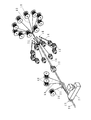
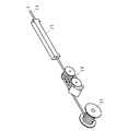
図1,図2は、本発明の光ファイバケーブルの製造方法を自己支持型光ファイバケーブルの製造に適用した実施の形態を説明するための生産ラインの説明図であり、図1のA点と図2のA点でつながる1つの図を分割して図示したものである。図中、10は光ファイバ心線、11は光ファイバ心線供給リール、12は光ファイバ心線集合体、13は繊維材料供給リール、14は繊維材料、15はガイドローラ、16はケーブル本体、17は粗巻き糸、18は鋼線供給リール、19は鋼線、20は支持線供給リール、21は支持線、22は押出機、23はクロスヘッド、24は自己支持型光ファイバケーブル、25は冷却水槽、26は引取キャプスタン、27は巻取装置である。この製造ラインは、図7で説明した自己支持型光ファイバケーブルを製造するものとして説明する。
【0017】
光ファイバ心線10は、回転ケージ上に設けられた光ファイバ心線供給リール11より供給され、旋回されて撚り合わされながら集合されて、光ファイバ心線集合体12となる。この例では、光ファイバ心線10としてテープ状光ファイバ心線を用いて、10本のテープ状光ファイバ心線を集合させたが、集合させるテープ状光ファイバ心線の数や集合形状に応じて、テープ状光ファイバ心線を2段で集合させてもよく、また、3段以上で集合させてもよい。また、本発明では、光ファイバ心線はテープ状光ファイバ心線に限られるものではなく、単線の光ファイバ心線を用いてもよいものである。光ファイバ心線集合体12の上に、回転ケージ上に設けられた繊維材料供給リール13から供給されたクッション層を形成する繊維材料14が撚り合わされて、ケーブル本体16が形成される。1つの繊維材料供給リール13からは、1本または複数本の繊維材料が供給される。繊維材料14としては、ポリプロピレン繊維を用いたが、これに限られるものではない。また、繊維材料は、単繊維でも、単繊維を撚り合わせて糸状にしたものでもよい。繊維材料14は、後述するように、回転ケージ上に設けられた溝付きのガイドローラ15によって方向を変更されて光ファイバ集合体12に撚り合わされる。ガイドローラ15に代えて、回転しないピン部材など、繊維材料14の走行方向を変更できる部材であればよい。繊維材料14の撚り合わせ方向は、光ファイバ集合体12の旋回方向に対して同方向に撚り合わされる。繊維材料14の撚り合わせ方向を、光ファイバ集合体12の旋回方向に対して逆方向としてもよい。繊維材料14の撚り合わせのピッチは、光ファイバ集合体12の旋回のピッチと同一のピッチとする方法、あるいは、繊維材料14の撚り合わせのピッチを光ファイバ集合体12の旋回のピッチに対して大きいピッチまたは小さいピッチとする方法が採用できる。これらのようにして、繊維材料14を撚り合わせることによって、光ファイバ集合体12に繊維材料14が食い込むことがなく、保護層が形成されるとともに、光ファイバ集合体12の集合状態が崩れてばらけた状態となることを防止できる。ケーブル本体16は、必要に応じて、次の工程で、ナイロン糸等の粗巻き糸17でバインドされる。
【0018】
このようにして形成されたケーブル本体16は、直線状態を保ったまま押出機22のクロスヘッド23に導かれる。クロスヘッド23には、ケーブル本体16のシース部分に挿入される鋼線19と支持線21が同時に導入される。鋼線19は、例えば直径0.4〜1.0mm程度の単線であり、ケーブル本体16に加えられる圧縮歪みを軽減するために設けられるものである。鋼線供給リール18から供給され、クロスヘッド23に導入される。支持線21は支供線供給リール20から供給され、プリテンションを与えられてクロスヘッド23に導入される。
【0019】
ケーブル本体16,鋼線19,支持線21が導入されたクロスヘッド23において、熱可塑性樹脂等による共通シースが施され、かつ、図4〜図7で説明したように、間欠的にスリットが形成された瓢箪型の断面形状の自己支持型光ファイバケーブル24が出来上がる。クロスヘッド23を出たところでは、共通シースは硬化していない状態であり、冷却水槽25を通って冷却され、引取キャプスタン26で引き取られ、巻取装置27で巻き取られる。
【0020】
このように、光ファイバ心線と繊維材料を集合し、そのままシース押出機に導くようにした。しかも、この間はローラに巻き付くなどさせることなく、直線状態を保つようにした。なお、直線状態とは、必ずしも直線でなければならないものではなく、多少の曲がりがあってもよいが、曲がりがある場合には、曲げ半径を2m以上にすることが必要である。したがって、本明細書でいう直線状態とは、曲げ半径が2m以上の曲げ状態をいう。もちろん、曲げ半径が無限大の直線が含まれることは当然であり、むしろ、直線の場合が望ましいのである。
【0021】
直線状態でシースが施された後は、冷却され引き取られ、巻き取られる。したがって、従来のように、光ファイバ心線と繊維材料を集合した後に、一旦巻取って、再度くり出すことによって、繊維材料の包囲が乱れて配列乱れの原因になるようなことはない。
【0022】
このように、集合された光ファイバ心線上に、次の工程で繊維材料が撚り合わされる。この場合、集合された光ファイバ心線の集合位置から繊維材料が撚り合わされる位置までの距離が大きいと集合された光ファイバ心線の集合状態が僅かに崩れることがあっても、繊維材料の包囲にムラが生じて、繊維材料を均一に撚り合わせることができないことが分かった。
【0023】
したがって、本発明では、繊維材料の集合は、光ファイバ心線の集合の直後に行なうようにした。すなわち、光ファイバ心線の撚り合わせ集合点の後(光ファイバ集合体の進行方向側)に近接して繊維材料の集合点を配置するようにした。
【0024】
繊維材料の集合と光ファイバ心線の集合とは、それぞれ回転ケージを用いて行なわれるから、繊維材料の集合点と光ファイバ心線の集合点を近づけるには限度がある。
【0025】
図1で説明したように、繊維材料14を回転ケージ上に設けられた溝付きのガイドローラ15によって方向を変更されて光ファイバ集合体12に撚り合わされるようにしたことによって、繊維材料の集合点を光ファイバ心線の集合点の直後にもってくることが容易となる。
【0026】
図3は、繊維材料の集合点と光ファイバ心線の集合方法の説明図である。図中、図1と同様の部分には同じ符号を付して説明を省略する。光ファイバ心線10はP点で集合される。P点において、光ファイバ心線10は、仮想の円錘体の側面に沿って集合される。仮想の円錘体の頂角の1/2の角θ1 を集合角と呼べば、θ1 については、θ1 が45゜を超えると、集合に用いるガイドやダイスによって光ファイバ心線に外傷が生じやすくなるので、θ1 は45゜以下とするのがよい。
【0027】
P点の前方のQ点において繊維材料14が光ファイバ心線集合体12に撚り合わされるようにして集合される。繊維材料14も、仮想の円錘体の側面に沿うようにしてQ点に導かれる。この仮想の円錘体の頂角の1/2の角θ2 も45゜以下でとするのがよい。θ2 が45゜を超えると、繊維材料14が光ファイバ心線集合体12を締め付けやすくなり、光ファイバ心線集合体12の損失を増加させるという問題を生じる。
【0028】
P点とQ点との間の距離Lを小さくするために、繊維材料14が、ガイドローラ15によって方向を変更されるようにしてQ点に導かれることは上述したが、繊維材料供給リール13から方向変更点であるガイドローラ15に至るパスラインと光ファイバ心線集合体12の進行方向との間の角度θは、ほぼ90゜またはそれ以下とするのがよい。すなわち、繊維材料供給リール13から出た繊維材料14と光ファイバ心線集合体12の進行方向がなす角度θは、ほぼ90゜またはそれ以下とするのがよい。90゜を超えると、繊維材料供給リール13を装填した回転ケージを、光ファイバ心線供給リール11を装填した回転ケージと干渉しないように配置するようにすると、Q点をP点に近接させることができないことになるからである。この角度θをもって繊維材料供給リール13から出た繊維材料14は、ガイドローラ15によって方向を光ファイバ心線集合体12の進行方向側に変更されてQ点において、光ファイバ心線集合体12に集合される。光ファイバ心線10の集合点であるP点と繊維材料14の撚り合わせ点であるQ点との距離Lが大きいと、繊維材料14が撚り合わされる前に、光ファイバ心線がバラけたり、一部の心線がたるんで縄跳び現象を起こすことがある。したがって、Q点をP点に近接させるようにする。Q点をP点に近接させることによって、光ファイバ心線を整列して撚り合わされた状態で繊維材料14を集合させることができる。近接させる具体的な範囲としては、P点とQ点との距離Lが、0.1mより小さいと段取り作業などに問題があり、1.5mを超えると撚り合わせた光ファイバ心線がバラけたりする現象が生じやすくなることから、0.1m以上、1.5m以下にするのがよい。
【0029】
なお、光ファイバ心線を複数段の集合位置で集合させる場合には、最終段の集合位置がP点に相当する。
【0030】
上述した実施の形態では、自己支持型の光ファイバケーブルについて説明したが、本発明は、自己支持型の光ファイバケーブルに限られるものではなく、複数本の光ファイバ心線を撚り合わせ、その周囲に繊維材料を撚合わせる光ファイバケーブルの複数本を集合する光ファイバケーブル、さらに、その上にシースが施される光ファイバケーブル、あるいは、それらの複数本を抗張力体の周囲に集合する光ファイバケーブルなど、適宜の構造の光ファイバケーブルに適用できるものである。
【0031】
このように本発明は、光ファイバ心線の集合点と繊維材料の集合点とが近接されていることにより、集合工程で集合させた光ファイバ心線の上に繊維材料を撚り合わせる工程に入る前に、集合させた光ファイバ心線がばらけてしまうことを防止でき、さらには、シースを施す工程を含めてこれらを直線状態で、かつ、一工程で行なうことを可能にして、コストを低下させるとともに、好適な条件で製造を行ない、品質を良好かつ安定に保ち得る光ファイバケーブルを製造することができる。
【0032】
【発明の効果】
以上の説明から明らかなように、請求項1または3に記載の発明によれば、光ファイバ心線の配列やピッチの乱れを防ぐことができ、断面配列が安定した状態で繊維材料を撚り合わせることができる。
【0033】
請求項2または4に記載の発明によれば、光ファイバ心線の撚り合わせ集合点の前方の0.1m以上、1.5m以下の距離に繊維材料の集合点を配置することが容易となるという効果がある。
【図面の簡単な説明】
【図1】本発明の光ファイバケーブルの製造方法を自己支持型光ファイバケーブルの製造に適用した実施の形態を説明するための生産ラインの一部の説明図である。
【図2】本発明の光ファイバケーブルの製造方法を自己支持型光ファイバケーブルの製造に適用した実施の形態を説明するための生産ラインの一部の説明図である。
【図3】繊維材料の集合点と光ファイバ心線の集合方法の説明図である。
【図4】自己支持型光ファイバケーブルの一例を説明するための斜視図である。
【図5】自己支持型光ファイバケーブルの一例を説明するための斜視図である。
【図6】自己支持型光ファイバケーブルの一例の説明図である。
【図7】自己支持型光ファイバケーブルの一例の断面図である。
【符号の説明】
1…支持線、2…ケーブル本体、2a…テープ状光ファイバ心線、2b…繊維材料、3a,3b…シース、3c…首部、4…スリット、5…支持線部、6…ケーブル本体部、7…鋼線、8…引き裂き紐、10…光ファイバ心線、11…光ファイバ心線供給リール、12…光ファイバ心線集合体、13…繊維材料供給リール、14…繊維材料、15…ガイドローラ、16…ケーブル本体、17…粗巻き糸、18…鋼線供給リール、19…鋼線、20…支持線供給リール、21…支持線、22…押出機、23…クロスヘッド、24…自己支持型光ファイバケーブル、25…冷却水槽、26…引取キャプスタン、27…巻取装置。[0001]
BACKGROUND OF THE INVENTION
The present invention relates to a method and an apparatus for manufacturing an optical fiber cable in which a plurality of optical fiber cores are twisted and a fiber material is twisted around the core.
[0002]
[Prior art]
When a self-supporting optical fiber cable in which a support line and a cable body are integrated by a sheath is suspended in an aerial space, the cable body is held by fixing both ends of the support line to a power pole. The advantage of this cable is that the support wire and the cable main body are integrated, so that it is not necessary to negotiate the support wire alone, and the work efficiency is such that only one negotiation work is required. However, when the self-supporting optical fiber cable is suspended, the tension applied to the support line is several hundred kgf, and the elongation is about 0.2%. It is a big problem from the viewpoint of long-term reliability that an elongation of about 0.2% is constantly applied to the optical fiber core.
[0003]
An example of a self-supporting optical fiber cable that solves this problem is shown in FIGS. In the figure, 1 is a support wire, 2 is a cable body, 3a and 3b are sheaths, 3c is a neck portion, 4 is a slit, 5 is a support wire portion, and 6 is a cable body portion. In this self-supporting optical fiber cable, the
[0004]
There is an optical fiber assembly at the center of the cable body of the self-supporting optical fiber cable with the saddle-shaped sheath, and the outside is completely covered with a cushioning filler of a plurality of fiber materials used as a protective material. However, there is known one using an optical fiber cable provided with a sheath on the outside thereof.
[0005]
FIG. 7 is a cross-sectional view of an example of a self-supporting optical fiber cable using such a fiber material as a protective material. In the figure, the same parts as those in FIGS. 2a is a tape-shaped optical fiber, 2b is a fiber material, 7 is a steel wire, and 8 is a tear string. In this example, an assembly of a plurality of tape-shaped optical fibers 2a is used as an optical fiber assembly. The assembled tape-shaped optical fiber 2a is twisted and provided in a swiveled state, and the fiber material 2b is provided so as to be twisted around the assembled tape-shaped optical fiber 2a. Yes. The
[0006]
The optical fiber cable having the cable body as described in FIG. 7 and having the sheath provided thereon is assembled by twisting the fiber material and twisting the fiber material, and then winding the sheath once. Generally, the process is shifted to a coating process, and the sheath is applied in a process separate from the process of assembling the optical fiber core wires. The quality problem in such a conventional manufacturing method is that the fiber material becomes non-uniform around the assembly of optical fibers, and the optical fiber inside may jump out of the fiber material. Even if it does not jump out, it is difficult to provide the fiber material uniformly because the fiber material is biased and the sheath does not become a clean circle. The disordered arrangement of the fiber material may cause harmful distortion to the optical fiber, and the difference in the elongation of the fiber material may cause uneven stretching in the longitudinal direction, resulting in an increase in loss.
[0007]
Even in the manufacturing method in which the process of assembling the optical fiber and the process of twisting the fiber material are performed in one step, and further in the manufacturing method in which the entire process is performed in one step continuously until the step of covering the sheath, the collected light If the assembled optical fibers are scattered before entering the step of twisting the fiber material on the fiber, there is a problem that the fiber material cannot be twisted uniformly.
[0008]
The optical fiber and the fiber material are twisted together by a rotating cage. However, when the optical fiber and the fiber material are arranged in the same cage, the twisting pitch and the twisting direction of the optical fiber and the fiber material are always the same. When the fiber material cage is placed in front of the optical fiber twisting cage, there is a long distance from twisting the optical fiber to twisting the fiber material, which may cause optical fiber misalignment or trauma. There is.
[0009]
[Problems to be solved by the invention]
The present invention has been made in view of the above-described circumstances, and the assembled optical fiber cores are scattered before entering the step of twisting the fiber material onto the optical fiber cores assembled in the assembly process. It is an object of the present invention to provide an optical fiber cable manufacturing method and manufacturing apparatus that can prevent the occurrence of damage, disorder of arrangement, and damage.
[0010]
[Means for Solving the Problems]
According to the first aspect of the present invention, a plurality of optical fiber cores are assembled to form an optical fiber core assembly, and a sheath is attached to a cable body in which fiber materials are assembled around the optical fiber core assembly. a method of manufacturing a coated optical fiber cables, in close proximity to the traveling direction of the optical fiber assembly of the set point of the optical fiber is arranged a set point of the fiber material, assembled with the fiber material In a method of manufacturing an optical fiber cable in which a cable body is supplied to an extruder in a substantially straight state to continuously cover a sheath, a distance between an assembly point of the optical fiber core wires and an assembly point of the fiber material is 0.1 m. As mentioned above, it is 1.5 m or less .
[0012]
According to a second aspect of the present invention, in the method for manufacturing an optical fiber cable according to the first aspect , the fiber material has a direction of the fiber material coming from a supply source and a traveling direction of the optical fiber core assembly. An angle of about 90 ° or less is supplied in a direction opposite to the traveling direction of the optical fiber core assembly, and the optical fiber core assembly is provided before the assembly point of the fiber material. The traveling direction is changed toward the traveling direction, and the assembly is performed.
[0013]
According to a third aspect of the present invention, an optical fiber core assembly is formed by assembling a plurality of optical fiber cores, and a sheath is attached to a cable body in which fiber materials are assembled around the optical fiber core assembly. an apparatus for producing a coated optical fiber cable, a set guide or collectively die in proximity to the traveling direction of the optical fiber assembly of the set guide or collection die to assemble the optical fiber is set fiber material And an assembly guide for assembling the optical fiber cores in an apparatus for manufacturing an optical fiber cable in which an extruder is disposed so as to continuously cover the sheath of the cable body in which the fiber materials are assembled in a substantially straight state. or the distance between the set guide or collection die to assemble a set die the fiber material 0.1m or more, to wherein a is 1.5m or less It is intended.
[0015]
According to a fourth aspect of the present invention, in the optical fiber cable manufacturing apparatus according to the third aspect , the fiber material has a direction of the fiber material coming from the supply source and a traveling direction of the optical fiber core assembly. An angle of about 90 ° or less is supplied in a direction opposite to the traveling direction of the optical fiber core assembly, and the optical fiber core assembly is provided before the assembly point of the fiber material. The traveling direction is changed toward the traveling direction, and the fiber material is introduced into a collecting guide or a collecting die that collects the fiber materials.
[0016]
DETAILED DESCRIPTION OF THE INVENTION
1 and 2 are explanatory views of a production line for explaining an embodiment in which the method for producing an optical fiber cable of the present invention is applied to the production of a self-supporting type optical fiber cable. FIG. 3 is a diagram in which one figure connected at point A in FIG. 2 is divided. In the figure, 10 is an optical fiber core, 11 is an optical fiber core supply reel, 12 is an optical fiber core assembly, 13 is a fiber material supply reel, 14 is a fiber material, 15 is a guide roller, 16 is a cable body, 17 is a coarsely wound yarn, 18 is a steel wire supply reel, 19 is a steel wire, 20 is a support wire supply reel, 21 is a support wire, 22 is an extruder, 23 is a crosshead, 24 is a self-supporting optical fiber cable, 25 Is a cooling water tank, 26 is a take-up capstan, and 27 is a winding device. This manufacturing line will be described on the assumption that the self-supporting optical fiber cable described in FIG. 7 is manufactured.
[0017]
The
[0018]
The
[0019]
In the
[0020]
In this way, the optical fiber core and the fiber material were assembled and guided to the sheath extruder as it was. Moreover, during this time, the straight state was maintained without wrapping around the roller. Note that the straight state does not necessarily have to be a straight line and may have some bends, but if there is a bend, the bend radius needs to be 2 m or more. Therefore, the straight state in the present specification means a bent state having a bending radius of 2 m or more. Of course, it is natural that a straight line having an infinite bending radius is included. Rather, a straight line is desirable.
[0021]
After the sheath is applied in a straight state, it is cooled, taken up and wound up. Therefore, unlike the conventional case, the optical fiber core and the fiber material are gathered, and then wound up once and then pulled out again, so that the surrounding of the fiber material is not disturbed and the arrangement is not disturbed.
[0022]
In this way, the fiber material is twisted on the assembled optical fiber core wires in the next step. In this case, even if the assembled state of the assembled optical fiber cores may be slightly collapsed if the distance from the assembly position of the assembled optical fiber cores to the position where the fiber material is twisted is large, the fiber material It was found that the surroundings were uneven and the fiber material could not be twisted together.
[0023]
Therefore, in the present invention, the assembly of the fiber material is performed immediately after the assembly of the optical fiber core wires. That is, the fiber material assembly point is arranged in the vicinity of the twisted assembly point of the optical fiber core wires (on the traveling direction side of the optical fiber assembly).
[0024]
Since the assembly of the fiber material and the assembly of the optical fiber cores are respectively performed using a rotating cage, there is a limit in bringing the assembly point of the fiber material and the assembly point of the optical fiber core wires close to each other.
[0025]
As described with reference to FIG. 1, the
[0026]
FIG. 3 is an explanatory diagram of a method for assembling a fiber material aggregation point and an optical fiber core wire. In the figure, the same parts as those in FIG. The
[0027]
The
[0028]
As described above, in order to reduce the distance L between the point P and the point Q, the
[0029]
Note that when the optical fiber cores are assembled at a plurality of stages of gathering positions, the last stage gathering position corresponds to the point P.
[0030]
In the above-described embodiments, the self-supporting optical fiber cable has been described. However, the present invention is not limited to the self-supporting optical fiber cable, and a plurality of optical fiber cores are twisted together and their surroundings are arranged. An optical fiber cable that collects a plurality of optical fiber cables in which fiber materials are twisted together, and an optical fiber cable that is sheathed thereon, or an optical fiber cable that collects a plurality of them around a tensile body The present invention can be applied to an optical fiber cable having an appropriate structure.
[0031]
As described above, the present invention enters the step of twisting the fiber material on the optical fiber cores assembled in the assembly process because the assembly point of the optical fiber cores and the assembly point of the fiber materials are close to each other. It is possible to prevent the assembled optical fiber cores from being scattered before, and further, it is possible to perform these in a straight line and a single process including the process of applying the sheath, thereby reducing the cost. It is possible to manufacture an optical fiber cable that can be reduced and manufactured under suitable conditions to maintain good and stable quality.
[0032]
【The invention's effect】
As is apparent from the above description, according to the invention described in
[0033]
According to invention of
[Brief description of the drawings]
FIG. 1 is an explanatory view of a part of a production line for explaining an embodiment in which the method for producing an optical fiber cable of the present invention is applied to the production of a self-supporting optical fiber cable.
FIG. 2 is an explanatory view of a part of a production line for explaining an embodiment in which the method for producing an optical fiber cable of the present invention is applied to the production of a self-supporting optical fiber cable.
FIG. 3 is an explanatory diagram of a method of assembling fiber material assembly points and optical fiber core wires.
FIG. 4 is a perspective view for explaining an example of a self-supporting optical fiber cable.
FIG. 5 is a perspective view for explaining an example of a self-supporting optical fiber cable.
FIG. 6 is an explanatory diagram of an example of a self-supporting optical fiber cable.
FIG. 7 is a cross-sectional view of an example of a self-supporting optical fiber cable.
[Explanation of symbols]
DESCRIPTION OF
Claims (4)
前記光ファイバ心線の集合点と前記繊維材料の集合点との距離が0.1m以上、1.5m以下であることを特徴とする光ファイバケーブルの製造方法。 An optical fiber cable manufacturing method in which a plurality of optical fiber cores are assembled to form an optical fiber core assembly, and a fiber body is assembled around the optical fiber core assembly to cover a cable body with a sheath. The fiber material assembly point is arranged on the traveling direction side of the optical fiber core assembly with respect to the assembly point of the optical fiber cores, and the cable body assembled with the fiber material is supplied to the extruder in a substantially straight state. In the manufacturing method of the optical fiber cable which coat | covers a sheath continuously,
A method of manufacturing an optical fiber cable, wherein a distance between an aggregation point of the optical fiber cores and an aggregation point of the fiber material is 0.1 m or more and 1.5 m or less.
前記光ファイバ心線を集合させる集合ガイドまたは集合ダイスと前記繊維材料を集合させる集合ガイドまたは集合ダイスとの距離が0.1m以上、1.5m以下であることを特徴とする光ファイバケーブルの製造装置。 An optical fiber cable manufacturing apparatus in which a plurality of optical fiber cores are assembled to form an optical fiber core assembly, and a fiber body is assembled around the optical fiber core assembly to cover a cable body with a sheath. The assembly guide or assembly die for assembling the fiber material is arranged on the traveling direction side of the assembly of the optical fiber core wires of the assembly guide or assembly die for assembling the optical fiber core wires, and the cable is formed by assembling the fiber materials. In an optical fiber cable manufacturing apparatus in which an extruder is arranged so as to continuously cover a sheath in a substantially straight state,
Manufacturing of an optical fiber cable, wherein a distance between an assembly guide or assembly die for assembling the optical fiber core wires and an assembly guide or assembly die for assembling the fiber material is 0.1 m or more and 1.5 m or less apparatus.
Priority Applications (1)
| Application Number | Priority Date | Filing Date | Title |
|---|---|---|---|
| JP2000283517A JP4134500B2 (en) | 2000-09-19 | 2000-09-19 | Optical fiber cable manufacturing method and manufacturing apparatus |
Applications Claiming Priority (1)
| Application Number | Priority Date | Filing Date | Title |
|---|---|---|---|
| JP2000283517A JP4134500B2 (en) | 2000-09-19 | 2000-09-19 | Optical fiber cable manufacturing method and manufacturing apparatus |
Publications (2)
| Publication Number | Publication Date |
|---|---|
| JP2002090598A JP2002090598A (en) | 2002-03-27 |
| JP4134500B2 true JP4134500B2 (en) | 2008-08-20 |
Family
ID=18767869
Family Applications (1)
| Application Number | Title | Priority Date | Filing Date |
|---|---|---|---|
| JP2000283517A Expired - Lifetime JP4134500B2 (en) | 2000-09-19 | 2000-09-19 | Optical fiber cable manufacturing method and manufacturing apparatus |
Country Status (1)
| Country | Link |
|---|---|
| JP (1) | JP4134500B2 (en) |
Cited By (1)
| Publication number | Priority date | Publication date | Assignee | Title |
|---|---|---|---|---|
| JPH079494U (en) * | 1993-07-23 | 1995-02-10 | 三協フロンテア株式会社 | Circulation-type purification toilet tank using bacteria |
Families Citing this family (1)
| Publication number | Priority date | Publication date | Assignee | Title |
|---|---|---|---|---|
| WO2004011983A1 (en) * | 2002-07-30 | 2004-02-05 | Fujikura Ltd. | Optical fiber cable, and method of manufacturing the optical fiber cable |
-
2000
- 2000-09-19 JP JP2000283517A patent/JP4134500B2/en not_active Expired - Lifetime
Cited By (1)
| Publication number | Priority date | Publication date | Assignee | Title |
|---|---|---|---|---|
| JPH079494U (en) * | 1993-07-23 | 1995-02-10 | 三協フロンテア株式会社 | Circulation-type purification toilet tank using bacteria |
Also Published As
| Publication number | Publication date |
|---|---|
| JP2002090598A (en) | 2002-03-27 |
Similar Documents
| Publication | Publication Date | Title |
|---|---|---|
| JP3578076B2 (en) | Self-supporting cable and method of manufacturing the same | |
| JP7307859B2 (en) | fiber optic cable | |
| JP2015129887A (en) | Air pressure feed optical fiber cable | |
| JP2775966B2 (en) | Optical fiber unit | |
| WO2022004362A1 (en) | Optical cable and optical-cable manufacturing method | |
| JP2023073421A (en) | Optical fiber cable and method of producing cable core | |
| JP6462472B2 (en) | Optical fiber unit, optical fiber cable, and optical fiber unit manufacturing method | |
| JP4134500B2 (en) | Optical fiber cable manufacturing method and manufacturing apparatus | |
| JP5159648B2 (en) | Slot core, manufacturing method thereof, and optical fiber cable using the slot core | |
| WO2023079932A1 (en) | Optical fiber cable and method for laying optical fiber cable | |
| JP2013195744A (en) | Manufacturing device and manufacturing method for optical cable | |
| JPH10148739A (en) | Aerial assembled outdoor optical cable | |
| US6788857B2 (en) | Optical fiber cable, a method of manufacturing the optical fiber cable, and an installation for implementing the method | |
| JP2005091616A (en) | Optical fiber cable and method for manufacturing the same | |
| WO2013065625A1 (en) | Self-supporting optical fiber cable and mid-span access method | |
| JP2005055704A (en) | Optical fiber cable and method for manufacturing the same | |
| JP6782112B2 (en) | How to manufacture optical fiber cable | |
| GB1576339A (en) | Manufacture of elongate optical fibre waveguide structures | |
| JP3254386B2 (en) | Manufacturing method of self-supporting optical cable with extra length with slit | |
| JP2003027384A (en) | Rope for extending cable and method for producing the same | |
| JPS6273216A (en) | Optical fiber cable and its manufacture | |
| JP2867867B2 (en) | Manufacturing method of optical fiber cable with suspension wire | |
| JP2015114412A (en) | Optical cable and method of manufacturing the same | |
| JP2022190317A (en) | Optical fiber cable | |
| JP2023028559A (en) | Intermittently adhering optical fiber ribbon and optical fiber cable |
Legal Events
| Date | Code | Title | Description |
|---|---|---|---|
| A621 | Written request for application examination |
Free format text: JAPANESE INTERMEDIATE CODE: A621 Effective date: 20061026 |
|
| A977 | Report on retrieval |
Free format text: JAPANESE INTERMEDIATE CODE: A971007 Effective date: 20080131 |
|
| A131 | Notification of reasons for refusal |
Free format text: JAPANESE INTERMEDIATE CODE: A131 Effective date: 20080305 |
|
| A521 | Written amendment |
Free format text: JAPANESE INTERMEDIATE CODE: A523 Effective date: 20080423 |
|
| TRDD | Decision of grant or rejection written | ||
| A01 | Written decision to grant a patent or to grant a registration (utility model) |
Free format text: JAPANESE INTERMEDIATE CODE: A01 Effective date: 20080507 |
|
| A01 | Written decision to grant a patent or to grant a registration (utility model) |
Free format text: JAPANESE INTERMEDIATE CODE: A01 |
|
| A61 | First payment of annual fees (during grant procedure) |
Free format text: JAPANESE INTERMEDIATE CODE: A61 Effective date: 20080520 |
|
| R150 | Certificate of patent or registration of utility model |
Free format text: JAPANESE INTERMEDIATE CODE: R150 Ref document number: 4134500 Country of ref document: JP Free format text: JAPANESE INTERMEDIATE CODE: R150 |
|
| FPAY | Renewal fee payment (event date is renewal date of database) |
Free format text: PAYMENT UNTIL: 20110613 Year of fee payment: 3 |
|
| FPAY | Renewal fee payment (event date is renewal date of database) |
Free format text: PAYMENT UNTIL: 20110613 Year of fee payment: 3 |
|
| FPAY | Renewal fee payment (event date is renewal date of database) |
Free format text: PAYMENT UNTIL: 20120613 Year of fee payment: 4 |
|
| FPAY | Renewal fee payment (event date is renewal date of database) |
Free format text: PAYMENT UNTIL: 20130613 Year of fee payment: 5 |
|
| R250 | Receipt of annual fees |
Free format text: JAPANESE INTERMEDIATE CODE: R250 |
|
| R250 | Receipt of annual fees |
Free format text: JAPANESE INTERMEDIATE CODE: R250 |
|
| R250 | Receipt of annual fees |
Free format text: JAPANESE INTERMEDIATE CODE: R250 |
|
| R250 | Receipt of annual fees |
Free format text: JAPANESE INTERMEDIATE CODE: R250 |
|
| R250 | Receipt of annual fees |
Free format text: JAPANESE INTERMEDIATE CODE: R250 |
|
| R250 | Receipt of annual fees |
Free format text: JAPANESE INTERMEDIATE CODE: R250 |
|
| R250 | Receipt of annual fees |
Free format text: JAPANESE INTERMEDIATE CODE: R250 |
|
| EXPY | Cancellation because of completion of term |