JP4133375B2 - desk - Google Patents
desk Download PDFInfo
- Publication number
- JP4133375B2 JP4133375B2 JP2003020839A JP2003020839A JP4133375B2 JP 4133375 B2 JP4133375 B2 JP 4133375B2 JP 2003020839 A JP2003020839 A JP 2003020839A JP 2003020839 A JP2003020839 A JP 2003020839A JP 4133375 B2 JP4133375 B2 JP 4133375B2
- Authority
- JP
- Japan
- Prior art keywords
- top plate
- desktop panel
- support
- support member
- end portion
- Prior art date
- Legal status (The legal status is an assumption and is not a legal conclusion. Google has not performed a legal analysis and makes no representation as to the accuracy of the status listed.)
- Expired - Fee Related
Links
Images


Landscapes
- Tables And Desks Characterized By Structural Shape (AREA)
- Furniture Connections (AREA)
Description
【0001】
【発明の属する技術分野】
本発明は、天板の側縁に沿って配置されるサイドデスクトップパネルを設けるようにしたデスクに関するものである。
【0002】
【従来の技術】
オフィス等で使用されるデスクには、天板の側端部に沿ってサイドデスクトップパネルを取り付けるようにしたものがある。そして、このようなサイドデスクトップパネルによって、複数のデスクを天板の側縁同士を突き合わせて隣接配置した場合に、各天板の上方空間を区画するようにしている。このようなデスクの従来品としては、天板の反使用端に沿ってフロントデスクトップパネルを配置し、このフロントデスクトップパネルの側端部にサイドデスクトップパネルの後端部を保持させるとともに、サイドデスクトップパネルの下端部を天板に支持させた構成のものが挙げられる(例えば、特許文献1参照)。
【0003】
【特許文献1】
特開平11−127966号公報(第3図等)
【0004】
【発明が解決しようとする課題】
ところが、このような構成のデスクにおいて天板の反使用縁側における下方空間に配線ダクト等を設けている場合、天板を一時的に前方へ引き出してこの配線ダクトを上方へ開放し配線コードを出し入れすることができるようにするための天板移動機構を設けることがあるが、サイドデスクトップパネルがフロントデスクトップパネルと天板の両方に支持されている構成であるため、天板のみを前方へ引き出すことができず、一旦サイドデスクトップパネルを完全に取り外し、配線コードの配線ダクトへの収納後に天板を元の位置に戻してから再びサイドデスクトップパネルを取り付けなければならないために、配線作業が不便であるという問題がある。
【0005】
この他にも、天板の側端面にサイドデスクトップパネルを取り付けるように構成したものも考えられているが、このようなものであると、隣接配置したデスクの天板の側縁同士間にサイドデスクトップパネルが配置されることになって、天板の側縁同士を突き当てたデスクの隣接配置が不可能であり、複数のデスクを隣接配置した後でサイドデスクトップパネルの着脱をするためには、少なくとも1台のデスク自体を当該隣接配置位置から移動させるという面倒な作業が必須となる。
【0006】
そこで本発明は、以上のような問題に鑑みて、隣接配置されるデスクの一方の天板のみの使用領域を不当に狭めることなく、フロントデスクトップパネルの有無に関わりなく、且つ少なくとも後端部においては天板と縁を切った状態でサイドデスクトップパネルを取り付け得るようにしたデスクを提供しようとするものである。
【0007】
【課題を解決するための手段】
すなわち本発明のデスクは、天板と、天板を下方から支持する天板受けと、天板受けを下方から支持する脚体とを具備し、天板の側縁部に沿ってサイドデスクトップパネルを配置し、天板の反使用縁に沿ってフロントデスクトップパネルを配置するようにしたものであって、サイドデスクトップパネルの後端部を、天板受けの後端部に着脱可能に取り付けられるサイドデスクトップパネル用支持部材に回動可能且つ着脱可能に支持させるように構成し、前記サイドデスクトップパネルの後端部を、前記天板の反使用縁の後方位置において天板の側縁を通る直線上で回動可能且つ着脱可能に支持するものであり、前記サイドデスクトップパネル用支持部材と、フロントデスクトップパネルの側端部を支持するフロントデスクトップパネル用支持部材とが、前記天板受けにそれぞれ着脱可能に取り着けられるものであるてなることを特徴とするものである。
【0008】
このような構成のデスクであれば、サイドデスクトップパネルを、天板受けに取り付けたサイドデスクトップパネル用支持部材に対して直接的又は間接的に着脱可能に支持させていることから、複数のデスクを隣接させて配置した後でも必要に応じてサイドデスクトップパネルを着脱することが可能となるため、作業性が著しく向上する。サイドデスクトップパネルは、サイドデスクトップパネル用支持部材に対して回動可能に設けられているため、例えば2台のデスクを隣接配置している際に、天板を一時的に前方へ引き出して反使用端部側の配線ダクト等を上方へ開放し配線コードを出し入れする場合などには、サイドデスクトップパネルを取り外さずに一方の天板側へ回動させることによって退避させれば他方の天板の前後動作が可能となる。また、隣接配置されるデスクの一方にのみサイドデスクトップパネルを取り付ければよいので、部品点数の削減やコストダウンを図ることも可能である。さらに、隣接配置されるデスクの両方の天板の上方空間に対して、それらの側縁に沿ってサイドデスクトップパネルの厚み寸法の半分ずつ略均等に配置することができるので、天板の側縁同士を突き当てた場合に何れか一方のみの天板の使用領域を狭めるということがない。
【0009】
また、サイドデスクトップパネルは天板とは直接関係なく天板受けに支持されているため、天板を天板受けに対して所定範囲内で前後方向に移動させ得る天板移動機構をこのデスクに設けたとしても、少なくともサイドデスクトップパネルの後端部側においては天板の移動を妨げることがなく、天板の移動時にサイドデスクトップパネルを完全に天板受けから取り外す必要もない。この場合、特にサイドデスクトップパネルの下縁を天板の上面から離間させることで、サイドデスクトップパネルの存在による天板の前後移動への干渉をさらに低減することができる。
【0010】
具体的に、サイドデスクトップパネルをサイドデスクトップパネル用支持部材に対して容易に回動可能且つ着脱可能とするためには、サイドデスクトップパネルの後端部を、当該後端部と前記サイドデスクトップパネル用支持部材との間に介在させた後部支持軸によって着脱可能に支持させるように構成することが好ましい。この場合、後部支持軸を回動中心としてサイドデスクトップパネルを水平回動可能とすれば、上述したように複数のデスクを隣接配置した場合に、サイドデスクトップパネルを一時的に一方のデスクの天板側へ回動により移動させておき、他方の天板を前後移動させて配線作業を行うことが容易に実現できるので、このような配線作業が非常に便利となる。
【0011】
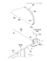
さらに、サイドデスクトップパネルの前端部側における支持構造の一例としては、天板の使用端部において隣接配置される他のデスクの天板との境界部位となる前記天板の側縁上にクランプ部材を着脱可能に取り付けるとともに、このクランプ部材に支持させた前部支持軸によってサイドデスクトップパネルの前端部を着脱可能に支持させるように構成したものが挙げられる。この場合、クランプ部材における天板への挟持部を緩めた状態とすれば、サイドデスクトップパネルを取り外さなくても、サイドデスクトップパネルをクランプ部材と共に後部支持軸を中心とする回動動作によって一方の天板側へ退避させることができるため、天板の前後移動を伴う配線作業をより簡便に行うことができるようになる。
【0012】
以上の構成に加えて、天板受けに対するサイドデスクトップパネル用支持部材の着脱作業の容易化を図るには、サイドデスクトップパネル用支持部材を、天板受けに対して下方から着脱可能とすることが望ましい。
【0013】
また、サイドデスクトップパネルの前端部側における支持構造は、上述のようなクランプ部材を用いたものに限らず、後端部側の支持構造と同様に、サイドデスクトップパネルの前端部を天板受けの前端部に着脱可能に取り付けられるサイドデスクトップパネル用支持部材に支持させた前部支持軸によって支持させるようにしたものとすることもできる。
【0014】
このようなサイドデスクトップパネルを備えたデスクにおいては、天板の反使用端部に沿ってフロントデスクトップパネルを配置し得るように構成することも可能である。特に、フロントデスクトップパネルの両側端部を、天板受けに着脱可能に取り付けられるフロントデスクトップパネル用支持部材に支持される側部支持軸によって支持させるように構成すれば、サイドデスクトップパネルと同様の構成によってフロントデスクトップパネルの配置が可能となる。
【0015】
この場合、フロントデスクトップパネル用支持部材の着脱作業をも容易化するには、フロントデスクトップパネル用支持部材を、天板受けに対して下方から着脱可能とすることが好ましい。具体的に、サイドデスクトップパネル及びフロントデスクトップパネルの支持構造をコンパクトにとりまとめて、省スペース化を図るためには、サイドデスクトップパネル用支持部材に隣接させてフロントデスクトップパネルを配置し得るように構成するとよい。
【0016】
【発明の実施の形態】
以下、本発明の一実施形態を、図面を参照して説明する。
【0017】
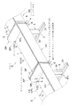
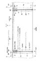
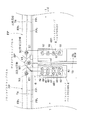
図1に斜視図、図2に正面図、図3に平面図をそれぞれ示す本実施形態は、オフィス等において執務用に使用されるデスクDである。このデスクDは主として、天板1と、この天板1を支持する一対の天板受け2、及び各天板受け2を支持する一対の脚体3によって構成されており、天板1の反使用縁1aに沿ってフロントデスクトップパネルFPを、天板1の側縁1bに沿ってサイドデスクトップパネルSPを配置し得るようにしている。なお、図1〜図3は、同種の複数のデスクDを、それらの天板1の側縁1b同士を突き合わせて隣接配置した状態を示しており、サイドデスクトップパネルSPは、その厚み方向の中央部を隣接配置される天板1、1同士の境界となる側縁1b、1b上に位置付けて配置している。また図4は、1台のデスクDのみを示す側面図である。以下に、各部の具体的構成について説明する。
【0018】
まず天板1は、所定の幅寸法、奥行き寸法及び厚み寸法を有し概略矩形状をなすものである。本実施形態では天板1として、木製のものを適用しているが、必ずしもこの限りではなく、金属製その他の一般的な天板に適用される素材であれば適宜のものが利用できる。なお、天板1は天板受け2に対して前後方向へスライド移動可能とされており、そのためにこのデスクDには天板移動機構Xを設けているが、この点については後述する。
【0019】
天板受け2は、天板1の両側端部1bに沿ってその下面側に配置され、天板1を下方から支持するものである。本実施形態においてこれら天板受け2は、天板1の奥行き方向に長手方向を合致させた、例えばアルミダイキャスト等により形成される長尺な部材であり、奥行き方向中央部を通り天板1の幅方向と平行な鉛直面を境にして前後面対称に形成してあって、天板1の側端部1bの左右を問わず使用できるようにしている。詳述すると、図5、図6及び図7に示すようにこの天板受け2は、主として左右に対をなす内側壁21及び外側壁22、前後に対をなす前壁23及び後壁24、並びに底壁(図示省略)によって構成され、上方へ開放した中空の部材である。また、内側壁21と外側壁22との間には、前壁23から後壁24に亘って前後に延びる一対の縦リブ25、25を底壁から起立させて設けるとともに、これら縦リブ25、25を横断するように複数の横リブ26を底壁から起立させて設けることによって天板受け2の強度向上を図っている。なお、各リブ25、26は、内側壁21及び外側壁22よりも高さ寸法を小さくしてある。また、これらリブ25、26に付帯させて複数箇所に、後述する天板移動機構Xを構成する移動ガイド部材X1を固定するために利用されるタップ孔2aや、この天板受け2を脚体3に固定するために利用されるタップ孔2bを形成している。天板受け2にはこの他にも、天板1の反使用端部1aに沿って配置されるフロントデスクトップパネルや側端部1bに沿って配置されるサイドデスクトップパネルを天板受け2に取り付ける際に利用されるタップ孔2c、2dも左右に並べて且つ下方に開口させて形成している。さらに、前端部及び後端部には、一対の縦リブ25、25間に亘って部分的に肉厚を設けた厚肉部27を形成しており、この厚肉部27に上下方向に亘って底壁24をも貫通させた貫通孔27aを形成している。また、内側壁21の前端部及び後端部においてちょうど前記厚肉部27の真横に該当する位置には、上縁の一部を矩形状に切り欠いた切欠部21aを形成している。この切欠部21aは、天板受け2に配線トレイ用ブラケットを取り付けるために利用されるものであるが、ここでは詳述を省略する。なお、内側壁21の奥行き方向中央部には、内向きに突出する角状突起部28が設けられており、左右の天板受け2の角状突起部28に角パイプ状をなす横桟29の両側端部を挿入してビス止めすることにより、左右の天板受け2を連結するようにしている。
【0020】
ここで、天板移動機構Xについて説明する。本実施形態において天板移動機構Xは、図5に示すように、天板1を天板受け2に対して所定範囲で前後にスライド移動させるためのものである。そのために、天板移動機構Xを、天板受け2に設けられる移動ガイド部材X1及びスライダX2、横桟29に設けられるローラX3及びストッパX4、天板2の下面側に設けられるスライド部材X5及び天板2の下面に形成されるストッパ係合孔X6によって構成している。
【0021】
移動ガイド部材X1は、金属板を折り曲げ加工して上片X11及び左右一対の側片X12を形成したものであり、左右の天板受け2にそれぞれ奥行き方向中央部を挟んで前後に対をなして2つずつ設けている。すなわち移動ガイド部材X1は、各側片X12、X12をそれぞれ内側壁21と一方の縦リブ25との間、外側壁22と他方の縦リブ25との間に挿入するとともに、上片X11を縦リブ25に載置して、上片X11の前端部及び後端部にそれぞれ2つずつ形成した貫通孔X13を前記タップ孔2aとそれぞれ合致させた位置でこれら貫通孔X13及びタップ孔2aに挿入されるビスX14により固定される。また、上片X11には前後方向に延びる長孔X15が形成してあり、この長孔X15の前後方向への開口長の範囲内で天板1を前後に移動させられるようにしている。なお、この長孔X15の前端部は、他の部位よりも広く開口させてある。これに対してスライド部材X5は、移動ガイド部材X1の長孔X15に対応して天板1の両側端部にそれぞれ前後に対をなして下面側から取り付けられるものであり、長孔と係合するスライド部材本体X51と、このスライド部材本体X51から上方へ突出させたネジ軸X52とからなり、ネジ軸X52を天板1の下面に螺合させている。スライド部材本体X51は、長孔X15の前端部の開口幅よりも小さく且つそれ以外の部位よりも大きい下部分と、移動ガイド部材X1の上片X11に載り長孔X15の各部よりも大きい円盤状をなす上部分とからなり、下部分と上部分とを移動ガイド部材X1の肉厚分程度離間させている。そして、天板1に取り付けたスライド部材X5の下部分を、天板受け2に取り付けた移動ガイド部材X1の長孔X15に対してその前端部から下方へ挿入することで、天板1を長孔X15に沿ってその開口長手寸法の範囲でスライド移動可能としている。
【0022】
ストッパX4は、横桟29の長手方向中央部においてその前面に取り付けられるストッパ本体X42に、図示しない押しボタン等の操作部を下方から押圧することで天板1の下面に対して上下に突没する係合片X41を備えた構成を有している。一方、天板1の下面における幅方向中央部には、上述した可動範囲において図3に示すように、天板1を最も手前(使用端1c側)へ引き出した引出位置Pと最も奥方(反使用端1a側)へ押し込んだ押込位置Qにおいて前記ストッパX4の係合片X41と対応するように、当該下面に穿設したストッパ係合孔X6を形成している。すなわち、天板1を引出位置P又は押込位置QにおいてストッパX4の操作部を操作して係合片X41を上動させてストッパ係合孔X6に挿入すれば、それらの位置P,Qで天板1を移動不能に固定することができ、操作部への操作により係合片X41を下降させておくと、係合片X41とストッパ係合孔X6との係合が解除されて天板1が前後方向にスライド移動し得る状態となる。
【0023】
また、スライダX2及びローラX3は、天板1の移動をスムーズに行うための構成部材である。まずスライダX2は、表面が滑らかな合成樹脂製の円柱状をなすスライダ本体X21と、このスライダ本体X21の下面から下方に突出させたネジ軸X22とからなり、ネジ軸X22を天板受け2の前端部における厚肉部27の貫通孔27aに螺合させることによって天板受け2に取り付けられ、スライダ本体X21の上面を天板1の下面に添接させて天板1の滑らかなスライド移動を実現するものである。ローラX3は、横桟29の長手方向中央部においてストッパX4の左右にそれぞれ1つずつ取り付けたものである。すなわち、水平軸を有する取付部材X31を横桟29の背面に取り付けて、水平軸に転動可能に支持させたローラ本体X32を横桟29の上面よりもやや上方に突出させている。そして、ローラ本体X32を天板1の下面に添接させており、天板1の前後移動時にローラ本体X32が水平軸回りに回転することによって、天板1のスムーズなスライド移動を実現するようにしている。なお、このような天板移動機構Xを設けた二台のデスクDを、天板1の反使用端1a同士を対面させて対面式で配置した場合、天板1同士の衝突による衝撃を緩和するために、各天板1の後向面の両側端部には、後方へ突出させた例えば合成樹脂製等の緩衝部材11、11をビス止めなどによって取り付けている。
【0024】
一対の脚体3、3は、いずれも同一構成を有するとともに、奥行き方向中央部を通る鉛直面を境に前後に面対称となるように形成したものであるので、左右を問わずに使用できるものである。また、これら脚体3、3は、天板受け2、2及び横桟29と共に門形の脚構造体を構成している。この脚体3は主として、床面に接地される脚ベース31と、脚ベース31の上面に立設され前後一対の鉛直中空部を有する支柱カバー32と、支柱カバー32の各鉛直中空部に挿入され下方から天板受け2を支持する前後一対の支柱33、33とから構成されており、支柱カバー32に対して支柱33、33を上下にスライド移動させることによって天板1の高さを変更し得る高さ調節機構Yを備えている。この高さ調節機構Yは、支柱カバー32の鉛直中空部内において脚ベース31に立設させた図示しない一対の芯材と支柱33、33とを、予め設定された複数の天板高さのうちから選択される一の天板高さにおいてビス止め等により係合させることにより、天板1の高さ変更を可能とするものである。
【0025】
サイドデスクトップパネルSPは、後端部を天板受け2の後端部に取り付けられるサイドデスクトップパネル用支持部材4に支持させた後部支持軸M1に支持させ、且つ前端部を天板1の使用縁部1aに取り付けられるクランプ部材6に支持させた前部支持軸M2に支持させた状態で配置される。以下、これら各部材の具体的構造及びサイドデスクトップパネルSPの支持構造について説明する。
【0026】
まず、サイドデスクトップパネルSPは、図6、図7、図8、図9、図11及び図12に示すように、前端部側の上端部に丸みを帯びさせた概略矩形板状をなすものであり、前端部側の下端部を矩形上に切り欠いた凹部SP3を形成している。このようなサイドデスクトップパネルSPは、上述した全体形状に対応した芯材SP1と、その両表面側を被覆するようにそれぞれ取り付けられる表面板SP2、SP2の合計3枚の板材を貼り合わせた構造を有するものである。そして、サイドデスクトップパネルSPの底面に開口させてその後端部及び前端部に、芯材SP1及び表面板SP2、SP2に亘る円筒状の孔部SP4、SP5を形成している。特に前端部側の孔部SP5は、前記凹部SP3の下向面に開口させてある。
【0027】
このようなサイドデスクトップパネルSPの後端部を支持するサイドデスクトップパネル用支持部材4は、例えばアルミダイキャスト等による起立板状をなす一体成形品であり、図6、図7、図8及び図9に示すように後端部側を外側方に向けて湾曲させている。サイドデスクトップパネル用支持部材4の後端部には、後部支持軸M1の下端部を上方から挿入させるための支持孔41を形成している。また、前後方向中央部から前端部に亘る領域には、上下に貫通させた貫通孔42を略一直線状に並べて複数形成している。そして、いずれか一つの貫通孔42を天板受け2の後端部に形成した外側のタップ孔2cに下方から一致させ、下方から貫通孔42に挿入したボルト4B1をタップ孔2cに締着することによって、このサイドデスクトップパネル用支持部材4を天板受け2に取り付けている。その際、サイドデスクトップパネル用支持部材4を天板受け2に隙間なく取り付けるために、サイドデスクトップパネル用支持部材4の上面は天板受け2の底壁及び後壁24の外面形状に対応させて、前端部側を低く且つ後端部側を高くしてその境界を滑らかに湾曲させて連続した形状としている。またこのとき、支持孔41の中心を、天板1の反使用縁1aの後方位置において天板1の側縁1bを通る直線上に位置付けるようにしている。後部支持軸M1は、このようにして天板受け2に取り付けられたサイドデスクトップパネル用支持部材4の後端部の支持孔41に下端部を挿入した状態で配置される金属製軸状部材である。そして、この後部支持軸M1の上端部をサイドデスクトップパネルSPの前端部側の孔部SP4に挿入することによって、サイドデスクトップパネルSPの後端部側を支持している。したがって、サイドデスクトップパネルSPは、その厚み方向の中央部が、隣接する天板1、1同士の境界となる側縁1b、1b上に位置付けられていることになる。
【0028】
サイドデスクトップパネルSPの前端部側を支持するクランプ部材5は、図11及び図12に示すように、天板1を上下に挟み込むことができる上片511及び下片512を具備する挟持部51と、天板1よりも上方に位置付けられ上方に開口する円筒部52を備え、図示しない操作部に対する操作によって挟持部51の上片511と下片512とを近接又は離反させて天板1を強く挟みつけ、或いは緩めることができるようにした通常の構成を有するものである。本実施形態では、サイドデスクトップパネルSPをその厚み方向の中央部を天板1の側縁1b上に位置付けるために、このクランプ部材5を隣接配置した天板1、1の前端部同士に跨って取り付けている。そして、円筒部52に金属製軸状部材である前部支持軸M2の下端部を上方挿入させた状態で、この前部支持軸M2の上端部をサイドデスクトップパネルSPの前端部における孔部SP5に下方から挿入することによって、サイドデスクトップパネルSPを起立姿勢となるように支持している。そしてこの状態で、サイドデスクトップパネルSPの下縁SP6は、天板1の上面よりも上方に位置付けるようにしている。このような支持構造では、クランプ部材5の挟持部51における上片511及び512による天板1の挟み込みを緩めた場合、クランプ部材5及び前部支持軸M2ごとサイドデスクトップパネルSPの前端部を左右に振れば、サイドデスクトップパネルSPは後部支持軸M1を回動中心とした水平回動動作を行い得ることになる。
【0029】
フロントデスクトップパネルFPは、両側端部を天板受け2の後端部に取り付けられるサイドデスクトップパネル用支持部材6に支持させた側部支持軸N1、N1に支持させた状態で配置される。以下、これら各部材の具体的構造及びフロントデスクトップパネルFPの支持構造について説明する。
【0030】
まず、フロントデスクトップパネルFPは、図6、図7、図8及び図10に示すように、全体として概略矩形板状をなすものであり、矩形板状をなす芯材FP1と、その両表面側を被覆するようにそれぞれ取り付けられる表面板FP2、FP2の合計3枚の板材を貼り合わせた構造を有するものである。そして、フロントデスクトップパネルSPの底面に開口させてその両側端部に、芯材FP1及び表面板FP2、FP2に亘る円筒状の孔部FP3、FP3を形成している。
【0031】
このようなフロントデスクトップパネルFPの両側端部を支持するフロントデスクトップパネル用支持部材6は、例えばアルミダイキャスト等による起立板状をなす一体成形品であり、サイドデスクトップパネル用支持部材とは異なり全体が略直線状の形状をなしている。フロントデスクトップパネル用支持部材6の後端部には、側部支持軸N1の下端部を上方から挿入させるための支持孔61を形成している。また、前後方向中央部から前端部に亘る領域には、上下に貫通させた貫通孔62を略一直線状に並べて複数形成している。そして、いずれか一つの貫通孔62を天板受け2の後端部に形成した内側のタップ孔2dに下方から一致させ、下方から貫通孔62に挿入したボルト6B1をタップ孔2dに締着することによって、このフロントデスクトップパネル用支持部材6をサイドデスクトップパネル用支持部材4の内側方に並べた状態で天板受け2に取り付けている。その際、フロントデスクトップパネル用支持部材6を天板受け2に隙間なく取り付けるために、フロントデスクトップパネル用支持部材6の上面は天板受け2の底壁及び後壁24の外面形状に対応させて、前端部側を低く且つ後端部側を高くしてその境界を滑らかに湾曲させて連続した形状としている。またこのとき、支持孔61の中心は、天板1の反使用縁1aの後方に位置付けられるようにしている。側部支持軸N1は、このようにして天板受け2に取り付けられたフロントデスクトップパネル用支持部材6の後端部の支持孔61に下端部を挿入した状態で配置される金属製軸状部材である。そして、フロントデスクトップパネルFPの両側端部において、この側部支持軸N1、N1の上端部をフロントデスクトップパネルFPの左右の孔部FP3、FP3にそれぞれ挿入することによって、フロントデスクトップパネルFPを起立姿勢で支持している。そしてこの状態で、フロントデスクトップパネルFP及びサイドデスクトップパネルSPの上縁同士及び下縁同士をそれぞれ同一の高さ位置に位置付けている。
【0032】
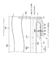
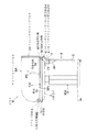
なお、このような構成のデスクにおいては、図13に示すように、天板1の反使用縁1b側において、天板1上のパーソナルコンピュータPC等の機器類の配線コードCを収容し案内する配線トレイ7や、天板1の下方空間を隠蔽するための幕板8等を設けることができる。本実施形態では、サイドデスクトップパネル用支持部材4やフロントデスクトップパネル用支持部材6に干渉させることなく、配線トレイ7を天板受け2に着脱可能に取り付けられる配線トレイ用ブラケット71を介して取り付け、幕板8を配線トレイ用ブラケット71に取り付けられる幕板用ブラケット71を介して取り付けるようにしているため、サイドデスクトップパネルSPやフロントデスクトップパネルFPの着脱、サイドデスクトップパネル用支持部材4やフロントデスクトップパネル用支持部材6の着脱、或いは天板1の天板移動機構Xを介した前後移動及びそれに伴うサイドデスクトップパネルSPの回動動作には、配線トレイ7及び幕板8の存在並びにこれらの取付構造は一切干渉しない。
【0033】
以上に説明したように、本実施形態のデスクDでは、サイドデスクトップパネルSPを天板受け2にサイドデスクトップパネル用支持部材6及び後部支持軸M1を介して且つこの後部支持軸M1を中心に回動可能に支持させており、さらにサイドデスクトップパネルSPを天板1の上方に離間させて配置しているため、図1に想像線で示すように、クランプ部材5を移動させない側の天板1の前縁1aに沿ってサイドデスクトップパネルSPと共に移動させるだけで、サイドデスクトップパネルSPを天板受け2から取り外すことなく前端部側を回動動作させて一方の天板1側へ一時的に退避させることによって、他方の天板1の前後移動を簡単に行い、配線作業を効率的にことができる。さらに、隣接配置されるデスクD、Dの天板1、1同士の境界となる側縁1b、1b上に幅方向中央部を合致させて、一方のデスクDにのみ付帯させてサイドデスクトップパネルSPを配置するようにしているため、これら隣接する何れか一方の天板1のみの使用領域が不当に狭められることがなく、いずれの天板1も等しく適当な広さで使用することができる。特に天板1は、天板移動機構Xによって前後にスライド移動させる構成を採用しており、反使用縁1b側に配線トレイ7を設ける場合には前方へ天板1を移動させることによって配線トレイ7を上方へ開放し配線コードCを出し入れする作業を行うことができるようにしている。また、フロントデスクトップパネルFPもサイドデスクトップパネルSPと同様に、フロントデスクトップパネル用支持部材6及び側部支持部材N1を介してコンパクトに天板受け2に取り付けているので、サイドデスクトップパネルSPの回動動作や天板1の前後動作に支障を来すことがない。さらに、このような構成とすることで、複数のデスクDを隣接配置した後で、サイドデスクトップパネルSP及びフロントデスクトップパネルFPを配置又は取り外すことができるため、これらの必要に応じた着脱動作を容易に行うことができる。
【0034】
なお、本発明のデスクは上述した実施形態に限られるものではない。例えばサイドデスクトップパネルの前端部は、クランプ部材以外の部材を用いて天板受けに支持させることができる。例えばサイドデスクトップパネルの前端部を天板の使用縁の前方に位置付けるようなものとするとともに、当該前端部に下方へ開口する支持孔を形成する一方、天板受けの前端部には後端部に取り付けられるサイドデスクトップパネル用支持部材と同様のものをその前端部が天板の前縁よりも前方に位置付けられるように取り付け、サイドデスクトップパネルの前端部及び後端部共に同様の支持軸を介して天板の側縁上に配置するようにしてもよい。また、フロントデスクトップパネルの支持構造も上述したものに限らず適宜の構成とすることができる。その他、サイドデスクトップパネルやフロントデスクトップパネルの、これらを支持する支持部材及び支持軸等の各部の具体的形状や構成についても上記実施形態に限られるものではなく、本発明の趣旨を逸脱しない範囲で種々変形が可能である。
【0035】
【発明の効果】
本発明は、以上に詳述したように、例えば隣接配置される天板の上方空間同士を間仕切りするためにサイドデスクトップパネルを設けるに際して、天板受けの後端部に取り付けられるサイドデスクトップパネル用支持部材及びこのサイドデスクトップパネル用支持部材に対して着脱可能且つ回動可能にサイドデスクトップパネルの後端部を支持させ、その状態でサイドデスクトップパネルを天板の側縁上に位置付けるように構成したものである。このため、デスクに天板を前後スライドさせる天板移動機構を設けたとしても、サイドデスクトップパネルの少なくとも後端部側の支持構造を干渉させずに天板を容易に移動させることができるので、このようなデスクを複数隣接配置した場合に、サイドデスクトップパネルを一方の天板側へ一時的に回動することにより退避させておけば、他方の天板の前後動作を容易に行うことができ、配線作業などの簡便さをも向上することができる。そのうえ、一方のデスクにのみサイドデスクトップパネルを取り付ければ、隣接する天板同士を効果的に区画できるので、部品点数の削減やコストダウンを図ることも可能である。さらに、サイドデスクトップパネルを天板やフロントデスクトップパネルにではなく、天板受けに支持させていることから、隣接配置後のデスクにサイドデスクトップパネルを後付けし又は撤去する作業性を格段に向上することができる。しかも、隣接配置されるデスクの一方の天板側に偏ることなく両方の天板に対して略均等にサイドデスクトップパネルを配置することができるので、いずれの天板においても適正な使用領域を確保することができる。また、デスクにフロントデスクトップパネルをサイドデスクトップパネルと直接的な関わりなく設けることによって、サイドデスクトップパネル単独の着脱を容易に行うことが可能である。
【図面の簡単な説明】
【図1】本発明の一実施形態のデスクを複数台隣接配置した状態を示す後方斜視図。
【図2】同正面図。
【図3】同平面図。
【図4】同デスクを示す側面図。
【図5】同デスクの天板移動機構を示す部分分解後方斜視図。
【図6】同デスクの反使用端側における構造を示す部分分解後方斜視図。
【図7】同組立状態を示す部分後方斜視図。
【図8】同部分拡大斜視図。
【図9】同デスクのサイドデスクトップパネルの後端部側における取付構造を示す部分断面図。
【図10】同デスクのフロントデスクトップパネルの位置側端部側における取付構造を示す部分断面図。
【図11】同デスクの使用端側における構造を示す部分分解斜視図。
【図12】同組立状態を示す部分斜視図。
【図13】同デスクに配線トレイ及び幕板を取り付けた状態を示す側面図。
【符号の説明】
D…デスク
FP…フロントデスクトップパネル
SP…サイドデスクトップパネル
M1…後部支持軸
M2…前部支持軸
N1…側部支持軸
X…天板移動機構
1…天板
1a…反使用縁
1b…側縁
1c…使用縁
2…天板受け
3…脚体
4…サイドデスクトップパネル用支持部材
5…クランプ部材
6…フロントデスクトップパネル用支持部材[0001]
BACKGROUND OF THE INVENTION
The present invention relates to a desk provided with a side desktop panel arranged along a side edge of a top board.
[0002]
[Prior art]
Some desks used in offices have side desktop panels attached along the side edges of the top board. Then, with such a side desktop panel, when a plurality of desks are arranged adjacent to each other with the side edges of the top plates being brought into contact with each other, the upper space of each top plate is partitioned. As a conventional product of such a desk, a front desktop panel is arranged along the counter-use end of the top plate, and the side desktop panel holds the rear end of the side desktop panel at the side edge of the front desktop panel. The thing of the structure which made the top plate support the lower end part of this is mentioned (for example, refer patent document 1).
[0003]
[Patent Document 1]
Japanese Patent Laid-Open No. 11-127966 (FIG. 3 etc.)
[0004]
[Problems to be solved by the invention]
However, in the desk with such a configuration, when a wiring duct or the like is provided in the lower space on the opposite side of the top plate, the top plate is temporarily pulled forward, the wiring duct is opened upward, and the wiring cord is taken in and out. The top desktop movement mechanism may be provided so that the side desktop panel is supported by both the front desktop panel and the top plate, so that only the top plate is pulled forward. Wiring work is inconvenient because the side desktop panel must be completely removed, the top panel must be returned to its original position after the wiring cord is stored in the wiring duct, and the side desktop panel must be attached again. There is a problem.
[0005]
In addition to this, a configuration in which a side desktop panel is attached to the side end surface of the top plate is also considered, but in such a case, the side between the side edges of the desk top plates arranged adjacent to each other is considered. Because the desktop panel is arranged, it is impossible to arrange the desks adjacent to each other on the side edges of the top board. To attach and detach the side desktop panel after arranging multiple desks adjacent to each other The troublesome work of moving at least one desk itself from the adjacent arrangement position is essential.
[0006]
Therefore, in view of the above problems, the present invention does not unduly narrow the use area of only one top plate of the adjacent desk, regardless of the presence or absence of the front desktop panel, and at least at the rear end. Is intended to provide a desk that can be fitted with a side desktop panel with the top plate cut off.
[0007]
[Means for Solving the Problems]
That is, the desk of the present invention includes a top plate, a top plate support that supports the top plate from below, and a leg that supports the top plate support from below, and a side desktop panel along the side edge of the top plate. Place And place the front desktop panel along the counter-use edge of the top plate The rear end portion of the side desktop panel is configured to be rotatably and detachably supported by a side desktop panel support member that is detachably attached to the rear end portion of the top plate receiver. Shi The rear end of the side desktop panel is supported so as to be rotatable and detachable on a straight line passing through the side edge of the top plate at a position behind the counter-use edge of the top plate. A support member and a front desktop panel support member for supporting a side end portion of the front desktop panel are detachably attached to the top plate receiver, respectively. It is characterized by.
[0008]
In the case of a desk having such a configuration, the side desktop panel is supported so as to be detachable directly or indirectly with respect to the support member for the side desktop panel attached to the top plate holder. Since the side desktop panel can be attached and detached as necessary even after being arranged adjacent to each other, workability is remarkably improved. Since the side desktop panel is provided so as to be rotatable with respect to the support member for the side desktop panel, for example, when two desks are arranged adjacent to each other, the top plate is temporarily pulled forward to be reused. When opening the wiring duct etc. on the end side and inserting / removing the wiring cord, if the side desktop panel is retracted by rotating it to one top plate without removing it, the front and back of the other top plate Operation is possible. Further, since the side desktop panel only needs to be attached to one of the desks arranged adjacent to each other, the number of parts can be reduced and the cost can be reduced. Furthermore, it is possible to arrange almost half of the thickness of the side desktop panel along the side edges of the top desks of both adjacent desks. When they are brought into contact with each other, the use area of only one of the top plates is not narrowed.
[0009]
In addition, since the side desktop panel is supported by the top plate receiver without being directly related to the top plate, this desk has a top plate moving mechanism that can move the top plate in the front-rear direction within a predetermined range with respect to the top plate receiver. Even if provided, the movement of the top plate is not hindered at least on the rear end side of the side desktop panel, and it is not necessary to completely remove the side desktop panel from the top plate holder when the top plate is moved. In this case, in particular, by separating the lower edge of the side desktop panel from the top surface of the top plate, interference with the back-and-forth movement of the top plate due to the presence of the side desktop panel can be further reduced.
[0010]
Specifically, in order to make the side desktop panel pivotable and detachable with respect to the side desktop panel support member, the rear end portion of the side desktop panel is connected to the rear end portion and the side desktop panel. It is preferable that the rear support shaft interposed between the support member and the support member is detachably supported. In this case, if the side desktop panel can be horizontally rotated with the rear support shaft as the center of rotation, the side desktop panel can be temporarily placed on the top plate of one desk when a plurality of desks are arranged adjacently as described above. Such wiring work is very convenient because it is possible to easily perform the wiring work by moving it to the side and moving the other top plate back and forth.
[0011]
Furthermore, as an example of the support structure on the front end side of the side desktop panel, a clamp member is provided on the side edge of the top plate that becomes a boundary portion with the top plate of another desk disposed adjacent to the use end of the top plate. And a structure in which the front end of the side desktop panel is detachably supported by the front support shaft supported by the clamp member. In this case, if the clamping part of the clamp member to the top plate is loosened, the side desktop panel can be moved together with the clamp member by the pivoting operation around the rear support shaft without removing the side desktop panel. Since it can be retracted to the board side, the wiring work accompanied by the back-and-forth movement of the top board can be performed more easily.
[0012]
In addition to the above configuration, in order to facilitate the attaching / detaching operation of the side desktop panel support member to the top plate receiver, the side desktop panel support member may be detachable from the top plate receiver from below. desirable.
[0013]
In addition, the support structure on the front end side of the side desktop panel is not limited to the one using the clamp member as described above, and the front end portion of the side desktop panel is the top plate support in the same manner as the support structure on the rear end side. It can also be made to be supported by a front support shaft supported by a side desktop panel support member that is detachably attached to the front end.
[0014]
In a desk provided with such a side desktop panel, the front desktop panel can be arranged along the counter-use end portion of the top plate. In particular, if both side ends of the front desktop panel are supported by side support shafts supported by front desktop panel support members that are detachably attached to the top plate holder, the same configuration as the side desktop panel Allows the placement of the front desktop panel.
[0015]
In this case, in order to facilitate the attaching / detaching operation of the front desktop panel support member, it is preferable that the front desktop panel support member be attachable / detachable from below with respect to the top plate support. Specifically, in order to make the support structure of the side desktop panel and the front desktop panel compact and to save space, the front desktop panel can be arranged adjacent to the side desktop panel support member. Good.
[0016]
DETAILED DESCRIPTION OF THE INVENTION
Hereinafter, an embodiment of the present invention will be described with reference to the drawings.
[0017]
1 is a perspective view, FIG. 2 is a front view, and FIG. 3 is a plan view. This embodiment is a desk D used for office work in an office or the like. The desk D mainly includes a
[0018]
First, the
[0019]
The
[0020]
Here, the top plate moving mechanism X will be described. In the present embodiment, the top plate moving mechanism X is for sliding the
[0021]
Moving guide member X 1 The upper piece X by bending the metal plate 11 And a pair of left and right side pieces X 12 And two pairs are provided on the left and right
[0022]
Stopper X Four The stopper body X is attached to the front surface of the
[0023]
Also, slider X 2 And Laura X Three Is a component for smoothly moving the
[0024]
The pair of
[0025]
The side desktop panel SP has a rear end supported by a rear support shaft M1 supported by a side desktop
[0026]
First, as shown in FIGS. 6, 7, 8, 9, 11, and 12, the side desktop panel SP has a substantially rectangular plate shape with a rounded upper end on the front end side. There is a recess SP with the lower end on the front end side cut out into a rectangle. Three Is forming. Such a side desktop panel SP is a core SP corresponding to the overall shape described above. 1 And a surface plate SP to be attached so as to cover both surface sides thereof 2 , SP 2 A total of three plate materials are bonded together. And it opens to the bottom face of side desktop panel SP, and core material SP is provided in the rear end part and the front end part. 1 And surface plate SP 2 , SP 2 Cylindrical hole SP Four , SP Five Is forming. Especially the hole SP on the front end side Five Is the recess SP Three It is opened on the downward surface.
[0027]
The side desktop
[0028]
As shown in FIGS. 11 and 12, the
[0029]
The front desktop panel FP is disposed in a state where both side ends are supported by side support shafts N1 and N1 supported by a side desktop
[0030]
First, as shown in FIGS. 6, 7, 8, and 10, the front desktop panel FP has a generally rectangular plate shape as a whole, and a core material FP that forms a rectangular plate shape. 1 And a surface plate FP attached to cover both surfaces 2 , FP 2 A total of three plate materials are bonded together. And it opens to the bottom face of front desktop panel SP, and core material FP is formed in the both ends. 1 And face plate FP 2 , FP 2 Cylindrical hole FP Three , FP Three Is forming.
[0031]
The front desktop
[0032]
In the desk having such a configuration, as shown in FIG. 13, the wiring code C of the equipment such as the personal computer PC on the
[0033]
As described above, in the desk D of the present embodiment, the side desktop panel SP is rotated to the
[0034]
The desk of the present invention is not limited to the above-described embodiment. For example, the front end portion of the side desktop panel can be supported by the top plate receiver using a member other than the clamp member. For example, the front end portion of the side desktop panel is positioned in front of the use edge of the top plate, and a support hole that opens downward is formed in the front end portion, while the rear end portion is formed in the front end portion of the top plate receiver. A side desktop panel support member that is attached to the side desktop panel is attached so that its front end portion is positioned forward of the front edge of the top plate, and both the front and rear end portions of the side desktop panel are connected via the same support shaft. It may be arranged on the side edge of the top plate. Further, the support structure of the front desktop panel is not limited to the above-described structure, and an appropriate configuration can be adopted. In addition, the specific shapes and configurations of the respective parts of the side desktop panel and the front desktop panel, such as the support member and the support shaft that support them, are not limited to the above-described embodiments, and do not depart from the spirit of the present invention. Various modifications are possible.
[0035]
【The invention's effect】
As described in detail above, the present invention provides a support for the side desktop panel that is attached to the rear end portion of the top plate holder, for example, when the side desktop panel is provided to partition the upper spaces of the adjacent top plates. The rear end portion of the side desktop panel is supported so as to be detachable and turnable with respect to the member and the support member for the side desktop panel, and the side desktop panel is positioned on the side edge of the top plate in that state. It is. For this reason, even if a top plate moving mechanism that slides the top plate back and forth on the desk is provided, the top plate can be easily moved without interfering with the support structure on at least the rear end side of the side desktop panel. When a plurality of such desks are arranged adjacent to each other, if the side desktop panel is retracted by temporarily rotating to one top plate side, the other top plate can be easily moved back and forth. In addition, the convenience of wiring work can be improved. In addition, if the side desktop panel is attached to only one of the desks, the adjacent top plates can be partitioned effectively, so the number of parts can be reduced and the cost can be reduced. Furthermore, since the side desktop panel is supported not by the top plate or the front desktop panel but by the top plate support, the workability of retrofitting or removing the side desktop panel to the desk after adjacent placement is greatly improved. Can do. In addition, the side desktop panel can be placed almost evenly on both top panels without being biased toward one of the top desks that are placed adjacent to each other. can do. Further, by providing the front desktop panel on the desk without being directly related to the side desktop panel, it is possible to easily attach and detach the side desktop panel alone.
[Brief description of the drawings]
FIG. 1 is a rear perspective view showing a state in which a plurality of desks according to an embodiment of the present invention are arranged adjacent to each other.
FIG. 2 is a front view of the same.
FIG. 3 is a plan view of the same.
FIG. 4 is a side view showing the desk.
FIG. 5 is a partially exploded rear perspective view showing a top plate moving mechanism of the desk.
FIG. 6 is a partially exploded rear perspective view showing the structure of the desk on the non-use end side.
FIG. 7 is a partial rear perspective view showing the assembled state.
FIG. 8 is an enlarged perspective view of the same part.
FIG. 9 is a partial cross-sectional view showing a mounting structure on the rear end side of the side desktop panel of the desk.
FIG. 10 is a partial cross-sectional view showing a mounting structure on the position side end portion side of the front desktop panel of the desk.
FIG. 11 is a partially exploded perspective view showing the structure on the use end side of the desk.
FIG. 12 is a partial perspective view showing the assembled state.
FIG. 13 is a side view showing a state where a wiring tray and a curtain are attached to the desk.
[Explanation of symbols]
D ... Desk
FP ... Front desktop panel
SP ... Side desktop panel
M1 ... Rear support shaft
M2 ... Front support shaft
N1 ... Side support shaft
X ... Top plate moving mechanism
1 ... top plate
1a ... Anti-use edge
1b ... side edge
1c ... Use edge
2 ... top plate holder
3 ... Legs
4. Support member for side desktop panel
5 ... Clamp member
6. Front desktop panel support member
Claims (12)
サイドデスクトップパネルの後端部を、天板受けの後端部に着脱可能に取り付けられるサイドデスクトップパネル用支持部材に対して回動可能且つ着脱可能に支持させるように構成し、
前記サイドデスクトップパネル用支持部材が、前記サイドデスクトップパネルの後端部を、前記天板の反使用縁の後方位置において天板の側縁を通る直線上で回動可能且つ着脱可能に支持するものであり、
前記サイドデスクトップパネル用支持部材と、フロントデスクトップパネルの側端部を支持するフロントデスクトップパネル用支持部材とが、前記天板受けにそれぞれ着脱可能に取り着けられるものであることを特徴とするデスク。A top plate, a top plate support that supports the top plate from below, and legs that support the top plate support from below; a side desktop panel is disposed along a side edge of the top plate; The front desktop panel is arranged along the counter-use edge ,
The rear end portion of the side desktop panel is configured to be rotatably and detachably supported with respect to the side desktop panel support member that is detachably attached to the rear end portion of the top plate receiver .
The support member for the side desktop panel supports the rear end portion of the side desktop panel so as to be rotatable and detachable on a straight line passing through the side edge of the top plate at a position behind the counter-use edge of the top plate. And
The desk according to claim 1, wherein the side desktop panel support member and the front desktop panel support member for supporting a side end portion of the front desktop panel are detachably attached to the top plate receiver .
Priority Applications (1)
| Application Number | Priority Date | Filing Date | Title |
|---|---|---|---|
| JP2003020839A JP4133375B2 (en) | 2003-01-29 | 2003-01-29 | desk |
Applications Claiming Priority (1)
| Application Number | Priority Date | Filing Date | Title |
|---|---|---|---|
| JP2003020839A JP4133375B2 (en) | 2003-01-29 | 2003-01-29 | desk |
Publications (2)
| Publication Number | Publication Date |
|---|---|
| JP2004229825A JP2004229825A (en) | 2004-08-19 |
| JP4133375B2 true JP4133375B2 (en) | 2008-08-13 |
Family
ID=32950361
Family Applications (1)
| Application Number | Title | Priority Date | Filing Date |
|---|---|---|---|
| JP2003020839A Expired - Fee Related JP4133375B2 (en) | 2003-01-29 | 2003-01-29 | desk |
Country Status (1)
| Country | Link |
|---|---|
| JP (1) | JP4133375B2 (en) |
Families Citing this family (2)
| Publication number | Priority date | Publication date | Assignee | Title |
|---|---|---|---|---|
| JP6675153B2 (en) * | 2015-04-30 | 2020-04-01 | 株式会社オカムラ | Top plate lifting fixtures |
| JP2016209140A (en) * | 2015-04-30 | 2016-12-15 | 株式会社岡村製作所 | Top board elevation type furniture |
-
2003
- 2003-01-29 JP JP2003020839A patent/JP4133375B2/en not_active Expired - Fee Related
Also Published As
| Publication number | Publication date |
|---|---|
| JP2004229825A (en) | 2004-08-19 |
Similar Documents
| Publication | Publication Date | Title |
|---|---|---|
| US6481586B1 (en) | Reversible shelving unit | |
| NO844839L (en) | ADJUSTABLE WORKSTATION AND EQUIPMENT FOR THIS | |
| JP2008062011A (en) | Furniture | |
| JP4133374B2 (en) | desk | |
| JP6787805B2 (en) | Storage device and installation method of storage device | |
| JP4133375B2 (en) | desk | |
| KR20110004902U (en) | Reading prop wihh monitor support structure | |
| JP2005034553A (en) | Desk having shelf device | |
| KR100532681B1 (en) | Receiving device structure for receiving computer peripherals and computer main body | |
| JP5304014B2 (en) | Desktop panel mounting device | |
| JPH0522Y2 (en) | ||
| JP4543642B2 (en) | Furniture with auxiliary top | |
| GB2413478A (en) | Demountable combination drawer cabinet | |
| JP4911465B2 (en) | Table system | |
| JP2009261841A5 (en) | ||
| JP4325582B2 (en) | Storage cabinet | |
| JP2015012973A (en) | Sliding storage device | |
| CN216464530U (en) | Can dismantle folding removal tool holder fast | |
| KR200192786Y1 (en) | A desk structure having slide type a drawer | |
| JP2004105487A (en) | Drawer table of kitchen cabinet and kitchen cabinet device | |
| EP1116088A4 (en) | Self-sustaining computer | |
| JP2705660B2 (en) | Drawer mounting structure | |
| JP3473326B2 (en) | Cabinet installation structure | |
| JP2001321229A (en) | Computer desk | |
| JP2005052296A6 (en) | Desk with shelf device |
Legal Events
| Date | Code | Title | Description |
|---|---|---|---|
| A621 | Written request for application examination |
Free format text: JAPANESE INTERMEDIATE CODE: A621 Effective date: 20050728 |
|
| A977 | Report on retrieval |
Free format text: JAPANESE INTERMEDIATE CODE: A971007 Effective date: 20080118 |
|
| A131 | Notification of reasons for refusal |
Free format text: JAPANESE INTERMEDIATE CODE: A131 Effective date: 20080212 |
|
| A521 | Written amendment |
Free format text: JAPANESE INTERMEDIATE CODE: A523 Effective date: 20080409 |
|
| TRDD | Decision of grant or rejection written | ||
| A01 | Written decision to grant a patent or to grant a registration (utility model) |
Free format text: JAPANESE INTERMEDIATE CODE: A01 Effective date: 20080513 |
|
| A01 | Written decision to grant a patent or to grant a registration (utility model) |
Free format text: JAPANESE INTERMEDIATE CODE: A01 |
|
| A61 | First payment of annual fees (during grant procedure) |
Free format text: JAPANESE INTERMEDIATE CODE: A61 Effective date: 20080602 |
|
| FPAY | Renewal fee payment (event date is renewal date of database) |
Free format text: PAYMENT UNTIL: 20110606 Year of fee payment: 3 |
|
| R150 | Certificate of patent or registration of utility model |
Free format text: JAPANESE INTERMEDIATE CODE: R150 |
|
| FPAY | Renewal fee payment (event date is renewal date of database) |
Free format text: PAYMENT UNTIL: 20110606 Year of fee payment: 3 |
|
| FPAY | Renewal fee payment (event date is renewal date of database) |
Free format text: PAYMENT UNTIL: 20120606 Year of fee payment: 4 |
|
| FPAY | Renewal fee payment (event date is renewal date of database) |
Free format text: PAYMENT UNTIL: 20120606 Year of fee payment: 4 |
|
| FPAY | Renewal fee payment (event date is renewal date of database) |
Free format text: PAYMENT UNTIL: 20130606 Year of fee payment: 5 |
|
| LAPS | Cancellation because of no payment of annual fees |