JP4133373B2 - Continuous wall waterproofing device - Google Patents
Continuous wall waterproofing device Download PDFInfo
- Publication number
- JP4133373B2 JP4133373B2 JP2003020774A JP2003020774A JP4133373B2 JP 4133373 B2 JP4133373 B2 JP 4133373B2 JP 2003020774 A JP2003020774 A JP 2003020774A JP 2003020774 A JP2003020774 A JP 2003020774A JP 4133373 B2 JP4133373 B2 JP 4133373B2
- Authority
- JP
- Japan
- Prior art keywords
- continuous wall
- receiving
- waterproof
- flange
- bent
- Prior art date
- Legal status (The legal status is an assumption and is not a legal conclusion. Google has not performed a legal analysis and makes no representation as to the accuracy of the status listed.)
- Expired - Fee Related
Links
Images


Landscapes
- Bulkheads Adapted To Foundation Construction (AREA)
Description
【0001】
【発明の属する技術分野】
本発明は連続壁の防水装置、特にH形鋼やI形鋼などの芯材が埋め込まれた連続壁の防水装置に関するものである。
【0002】
【従来の技術】
ソイルセメント柱列壁または泥水固化壁など(以下連続壁と称する)は仮設用の山留め壁や止水壁として構築され、その中に芯材としてH形鋼やI形鋼が埋め込まれている。この連続壁は構造物の地下を掘削する前に地下に施工され、その後の掘削により上記連続壁の芯材の前端部までを露出させることにより、地下空間を構築せしめている。
【0003】
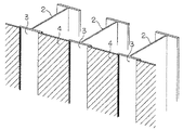
連続壁中に埋め込まれている芯材は本体構造物である地下外壁の構築後に地盤内に埋め殺しされるのが一般的であったが、近年においては、芯材を本体構造物の一部として有効利用するため、芯材のフランジ面にスタッドボルトを打設して外壁と一体化した合成壁工法を用いているが、上記スタッドボルトのため、連続壁の全面に防水シートを貼り付けて防水をはかることができない。そのため上記連続壁の芯材の前端部における防水は、従来においては図14及び図15に示すように、上記連続壁1に埋め込まれた各隣り合うH形鋼の芯材2の前端部のフランジ3間に鋼板4を溶接したり、図16に示すように、芯材2の前端部の全面に防水シート5を貼り付けていた。
【0004】
なお、公知例として特開平5−222741号公報、特開平8−296247号公報、特開平7−90875号公報、特開平9−242089号公報、特開平11−336109号公報、特開平11−293918号公報、特開平11−229413号公報、特開平11−50445号公報、特開2001−159146号公報、特開2001−200548号公報、特開2001−241054号がある。
【0005】
【発明が解決しようとする課題】
然しながら、従来の防水方法では、以下のような問題があった。
【0006】
(1)漏水を防止するため、各芯材のフランジへの鋼板の溶接は、全長に亘ってかつ確実に行う必要があり、施工に時間が掛かる。
【0007】
(2)ソイルセメントまたは泥水中への芯材の落とし込みの精度が十分に確保できないため、隣り合う芯材のフランジ面が必ずしも平行になっておらず、捩れ等が生じている。したがって、隣り合う芯材のフランジへの鋼板の取り付け及び溶接が困難である。
【0008】
(3)連続壁の前面への防水シートの貼り付けは、漏水のない芯材のフランジ面も覆うこととなるため、経済性を損なうこととなる。
【0009】
本発明は上記のような欠点を除くようにしたものである。
【0010】
【課題を解決するための手段】
本発明の連続壁の防水装置は、連続壁に埋め込まれる、少なくともその前端部にフランジを有する複数の芯材と、この各芯材のフランジの両側に設けた受け部と、互いに隣接する芯材の互いに隣接する上記受け部に夫々その両端折り曲げ部が挿入される防水板と、上記フランジの側面と、これに対応する上記防水板の折り曲げ端面間に嵌合される弾性体とよりなることを特徴とする。
【0012】
上記受け部が受け材によって形成され、この受け材の端部は、折り曲げられており、この折り曲げ角度と、上記防水板の上記折り曲げ角度が夫々90度以上であることを特徴とする。
【0014】
上記受け部は、C形状の溝であることを特徴とする。
【0015】
上記弾性体は、水膨張性であることを特徴とする。
【0017】
【発明の実施の形態】
以下図面によって本発明の実施例を説明する。
【0018】
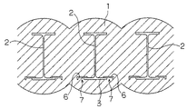
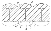
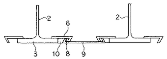
本発明の連続壁の防水装置においては、図1に示すように、H形鋼の芯材2の前端部側フランジ3の両側裏側に、夫々側方外方に伸びその端部を直角に外方に折り曲げたL字状の受け材6を予め溶接等で固着し、上記フランジ3の芯材2の両側部より外側に受け部7を構成せしめた後、この芯材2をソイルセメントまたは泥水中に埋め込んで連続壁1を構成し、図2に示すように、上記連続壁1に埋め込まれた芯材2の前端部が露出するまで地下(点線部分)を掘削し、図3に示すように、その両端に夫々折れ曲がり部8を有する鋼板などの防水板9の上記折れ曲がり部8を夫々上記隣り合う芯材2の受け部7に挿入し、上記前端部側フランジ3の両側部と上記防水板9の折れ曲がり部8との間に夫々ゴム等の弾性体10をはめ込み、止水せしめる。
【0019】
なお、上記弾性体10を水膨張性のものとすれば、水を含んでいない状態で上記部分にはめ込み、その後に弾性体10に水を供給すれば、より強固に上記防水板9を上記フランジ3に固定せしめることができ、また作業時間の短縮を図ることができる。
【0020】
また、図4に示すように、上記受け材6のL字部の折り曲げ角度と上記防水板9の折れ曲がり部8の折り曲げ角度を夫々90度以上とし、この部分が互いに重なり合って上記防水板9が上記受け部7から外方に外れないようにするのが好ましい。なお、この実施例においては上記防水板9は上記受け部7の上方からこれに挿入せしめる。
【0021】
図5は本発明の連続壁の防水装置の他の実施例を示し、この実施例においては防水板9を用いる代わりに、複数の隣り合う芯材2の離間距離に対応する長さの防水シート11を用い、上記防水シート11の両端部を夫々上記受け部7に挿入した状態で、上記受け部7に上記防水シート11の外側から弾性体10をはめ込み、止水せしめる。
【0022】
なお、図6に示すように、受け材6のL字部の折り曲げ角度を90度以上とし、受け部7から弾性体10を外れにくくするのが好ましい。
【0023】
また、上記受け材6を上記フランジ3面より前方に突出しないようにすれば、芯材2の前端部を露出するまで掘削する際、掘削機のバケットが受け材6に引っ掛かることなく掘削がスムーズに行えるとともに、フランジ面に付着した異物等を掘削機で容易に除去することができる。
【0024】
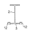
図7は本発明の更に他の実施例を示し、この実施例においては、上記L字状の受け材6を用いる代わりに、上記芯材2の前端部側フランジの両側端部に夫々コ字状の受け材12を固定し、上記この受け材12によって受け部7を構成せしめる。
【0025】
なお、この場合も図8に示すように、上記受け材12を上記フランジ3面より前方に突出しないようにすれば、芯材2の前端部が露出するまで掘削する際、掘削機のバケットが引っ掛かることなく掘削がスムーズに行えるとともに、フランジ面に付着した異物等を掘削機で容易に除去することができる。
【0026】
また、図9に示すように、上記コ字状の受け材12の代わりに、C形状の溝からなる受け材13を用いたり、図10及び図11に示すように、上記受け材12及び13の開口部を狭くし、上記受け部7から弾性体10を外れにくくしてもよい。
【0027】
また、図12及び図13に示すように、上記受け材12及び13の開口部を夫々フランジ3の側面外方に向くように上記フランジの両側端部に設けてもよい。
【0028】
【発明の効果】
本発明の連続壁の防水装置によれば、ソイルセメントまたは泥水中への芯材の落とし込みの精度が十分に確保できず芯材に捩れがあっても、また固化したソイルセメントまたは泥水が十分に削り落とされずフランジ面より突出している場合でも、鋼板や防水シート等の防水部材を弾性体で固定するようにしたため、多少の設置誤差に関わらず止水することができる大きな利益がある。
【0029】
また、防水シートをソイルセメントまたは泥水部のみに設置することにより、防水シートの量を低減することができ、また、フランジ面に固定物がある場合でも防水シートを固定することができる。
【0030】
また、従来のように防水シートとなる鋼板を溶接せずに、弾性体を嵌め込むことにより鋼板を固定できるからその設置作業を短縮することができる。
【0031】
また、受け材のL字部の角度や鋼材の両端の折り曲げ部の角度を90度以上にしたり、受け部の開口部を狭めることにより、より弾性体を外れにくくすることができる。
【図面の簡単な説明】
【図1】本発明の連続壁の防水装置の説明用平面図である。
【図2】本発明の連続壁の防水装置の説明用平面図である。
【図3】本発明の連続壁の防水装置の説明用平面図である。
【図4】本発明の連続壁の防水装置の他の実施例の説明用平面図である。
【図5】本発明の連続壁の防水装置の他の実施例の説明用平面図である。
【図6】本発明の連続壁の防水装置の更に他の実施例の説明用平面図である。
【図7】本発明の連続壁の防水装置の更に他の実施例の説明用平面図である。
【図8】本発明の連続壁の防水装置の更に他の実施例の説明用平面図である。
【図9】本発明の連続壁の防水装置の更に他の実施例の説明用平面図である。
【図10】本発明の連続壁の防水装置の更に他の実施例の説明用平面図である。
【図11】本発明の連続壁の防水装置の更に他の実施例の説明用平面図である。
【図12】本発明の連続壁の防水装置の更に他の実施例の説明用平面図である。
【図13】本発明の連続壁の防水装置の更に他の実施例の説明用平面図である。
【図14】従来の連続壁の防水装置の平面図である。
【図15】従来の連続壁の防水装置の斜視図である。
【図16】従来の他の連続壁の防水装置の斜視図である。
【符号の説明】
1 連続壁
2 芯材
3 フランジ
4 鋼板
5 防水シート
6 L字状受け材
7 受け部
8 折れ曲がり部
9 防水板
10 弾性体
11 防水シート
12 コ字状の受け材
13 受け材[0001]
BACKGROUND OF THE INVENTION
The present invention relates to a continuous wall waterproof device, and more particularly to a continuous wall waterproof device in which a core material such as H-shaped steel or I-shaped steel is embedded.
[0002]
[Prior art]
A soil cement column wall or a muddy water solidifying wall (hereinafter referred to as a continuous wall) is constructed as a temporary retaining wall or water-stopping wall, in which H-shaped steel or I-shaped steel is embedded as a core material. The continuous wall is constructed underground before excavating the underground of the structure, and the underground space is constructed by exposing the front end of the core of the continuous wall by subsequent excavation.
[0003]
The core material embedded in the continuous wall is generally buried in the ground after the construction of the underground outer wall, which is the main body structure. However, in recent years, the core material is part of the main body structure. In order to use it effectively, a synthetic wall construction method in which stud bolts are placed on the flange surface of the core material and integrated with the outer wall is used, but because of the stud bolts, a waterproof sheet is attached to the entire surface of the continuous wall. It cannot be waterproofed. Therefore, the waterproofing at the front end portion of the core material of the continuous wall is conventionally performed by the flanges at the front end portions of the adjacent H-shaped
[0004]
As publicly known examples, Japanese Patent Application Laid-Open Nos. H5-222241, H8-296247, H7-90875, H9-242089, H11-336109, H11-293918. JP-A-11-229413, JP-A-11-50445, JP-A-2001-159146, JP-A-2001-200548, and JP-A-2001-241054.
[0005]
[Problems to be solved by the invention]
However, the conventional waterproofing method has the following problems.
[0006]
(1) In order to prevent water leakage, it is necessary to reliably weld the steel plate to the flange of each core member over the entire length, and it takes time for construction.
[0007]
(2) Since the accuracy of dropping the core material into the soil cement or muddy water cannot be ensured sufficiently, the flange surfaces of the adjacent core materials are not necessarily parallel to each other, resulting in twisting. Therefore, it is difficult to attach and weld the steel plate to the flange of the adjacent core material.
[0008]
(3) Affixing the waterproof sheet to the front surface of the continuous wall also covers the flange surface of the core material without water leakage, which impairs economic efficiency.
[0009]
The present invention eliminates the above-mentioned drawbacks.
[0010]
[Means for Solving the Problems]
The continuous wall waterproofing device of the present invention includes a plurality of core members embedded in the continuous wall and having flanges at least at the front end thereof, receiving portions provided on both sides of the flanges of the respective core members, and core members adjacent to each other. Each of the receiving portions adjacent to each other includes a waterproof plate in which bent portions at both ends thereof are inserted, a side surface of the flange, and an elastic body fitted between the corresponding bent end surfaces of the waterproof plate. Features.
[0012]
The receiving portion is formed of a receiving material, and an end portion of the receiving material is bent, and the bending angle and the bending angle of the waterproof plate are respectively 90 degrees or more.
[0014]
The receiving portion is a C-shaped groove.
[0015]
The elastic body is water expandable.
[0017]
DETAILED DESCRIPTION OF THE INVENTION
Embodiments of the present invention will be described below with reference to the drawings.
[0018]
In the continuous wall waterproofing device of the present invention, as shown in FIG. 1, it extends laterally outward on both sides of the front
[0019]
If the
[0020]
Further, as shown in FIG. 4, the bending angle of the L-shaped portion of the receiving member 6 and the bending angle of the
[0021]
FIG. 5 shows another embodiment of the waterproof device for continuous walls according to the present invention. In this embodiment, instead of using the
[0022]
As shown in FIG. 6, it is preferable that the bending angle of the L-shaped portion of the receiving member 6 is 90 degrees or more so that the
[0023]
Further, if the receiving material 6 does not protrude forward from the surface of the
[0024]
FIG. 7 shows still another embodiment of the present invention. In this embodiment, instead of using the L-shaped receiving member 6, U-shapes are provided at both end portions of the front end side flange of the
[0025]
In this case as well, as shown in FIG. 8, if the receiving
[0026]
9, instead of the
[0027]
Further, as shown in FIGS. 12 and 13, the openings of the receiving
[0028]
【The invention's effect】
According to the continuous wall waterproof device of the present invention, the accuracy of dropping the core material into the soil cement or muddy water cannot be sufficiently ensured, and even if the core material is twisted, the solidified soil cement or muddy water is sufficient. Even if it is not scraped off and protrudes from the flange surface, a waterproof member such as a steel plate or a waterproof sheet is fixed with an elastic body, so that there is a great advantage that water can be stopped regardless of some installation errors.
[0029]
Further, by installing the waterproof sheet only on the soil cement or the muddy water part, the amount of the waterproof sheet can be reduced, and the waterproof sheet can be fixed even when there is a fixed object on the flange surface.
[0030]
Moreover, since the steel plate can be fixed by fitting the elastic body without welding the steel plate to be a waterproof sheet as in the prior art, the installation work can be shortened.
[0031]
Further, the elastic body can be made more difficult to come off by making the angle of the L-shaped portion of the receiving material and the angle of the bent portions at both ends of the steel material 90 degrees or more, or by narrowing the opening of the receiving portion.
[Brief description of the drawings]
FIG. 1 is a plan view for explaining a waterproof device for a continuous wall according to the present invention.
FIG. 2 is a plan view for explaining the waterproof device for a continuous wall according to the present invention.
FIG. 3 is a plan view for explaining the waterproof device for continuous walls according to the present invention.
FIG. 4 is a plan view for explaining another embodiment of the continuous wall waterproofing device of the present invention.
FIG. 5 is a plan view for explaining another embodiment of the waterproof device for continuous walls according to the present invention.
FIG. 6 is a plan view for explaining another embodiment of the continuous wall waterproofing device of the present invention.
FIG. 7 is a plan view for explaining another embodiment of the continuous wall waterproofing device of the present invention.
FIG. 8 is a plan view for explaining another embodiment of the continuous wall waterproofing device of the present invention.
FIG. 9 is a plan view for explaining still another embodiment of the continuous wall waterproof device of the present invention.
FIG. 10 is a plan view for explaining still another embodiment of the waterproof device for continuous walls according to the present invention.
FIG. 11 is a plan view for explaining another embodiment of the waterproof device for continuous walls according to the present invention.
FIG. 12 is a plan view for explaining another embodiment of the waterproof device for continuous walls according to the present invention.
FIG. 13 is a plan view for explaining still another embodiment of the waterproof device for continuous walls according to the present invention.
FIG. 14 is a plan view of a conventional continuous wall waterproofing device.
FIG. 15 is a perspective view of a conventional continuous wall waterproofing device.
FIG. 16 is a perspective view of another conventional continuous wall waterproofing device.
[Explanation of symbols]
DESCRIPTION OF
Claims (4)
Priority Applications (1)
| Application Number | Priority Date | Filing Date | Title |
|---|---|---|---|
| JP2003020774A JP4133373B2 (en) | 2003-01-29 | 2003-01-29 | Continuous wall waterproofing device |
Applications Claiming Priority (1)
| Application Number | Priority Date | Filing Date | Title |
|---|---|---|---|
| JP2003020774A JP4133373B2 (en) | 2003-01-29 | 2003-01-29 | Continuous wall waterproofing device |
Publications (2)
| Publication Number | Publication Date |
|---|---|
| JP2004232285A JP2004232285A (en) | 2004-08-19 |
| JP4133373B2 true JP4133373B2 (en) | 2008-08-13 |
Family
ID=32950311
Family Applications (1)
| Application Number | Title | Priority Date | Filing Date |
|---|---|---|---|
| JP2003020774A Expired - Fee Related JP4133373B2 (en) | 2003-01-29 | 2003-01-29 | Continuous wall waterproofing device |
Country Status (1)
| Country | Link |
|---|---|
| JP (1) | JP4133373B2 (en) |
Cited By (1)
| Publication number | Priority date | Publication date | Assignee | Title |
|---|---|---|---|---|
| CN107090828A (en) * | 2017-05-23 | 2017-08-25 | 五冶集团上海有限公司 | A kind of Larsen steel sheet pile construction method for buried cable pipeline protection |
Families Citing this family (4)
| Publication number | Priority date | Publication date | Assignee | Title |
|---|---|---|---|---|
| JP5515579B2 (en) * | 2009-10-01 | 2014-06-11 | 株式会社大林組 | Mountain retaining wall structure, method for constructing mountain retaining wall structure |
| JP2011117198A (en) * | 2009-12-03 | 2011-06-16 | Ohbayashi Corp | Earth retaining structure and construction method of the same |
| CN111827265A (en) * | 2020-07-21 | 2020-10-27 | 重鑫岩土技术(上海)有限公司 | Construction method of steel reinforced concrete underground continuous wall |
| CN113653201B (en) * | 2021-08-27 | 2022-09-13 | 中国建筑第五工程局有限公司 | Waterproof structure of lattice column and construction method thereof |
-
2003
- 2003-01-29 JP JP2003020774A patent/JP4133373B2/en not_active Expired - Fee Related
Cited By (1)
| Publication number | Priority date | Publication date | Assignee | Title |
|---|---|---|---|---|
| CN107090828A (en) * | 2017-05-23 | 2017-08-25 | 五冶集团上海有限公司 | A kind of Larsen steel sheet pile construction method for buried cable pipeline protection |
Also Published As
| Publication number | Publication date |
|---|---|
| JP2004232285A (en) | 2004-08-19 |
Similar Documents
| Publication | Publication Date | Title |
|---|---|---|
| US8820015B2 (en) | Shuttering element for a trench wall and method for producing the trench wall | |
| JP4757959B2 (en) | Steel sheet pile wall and its construction method | |
| JP4133373B2 (en) | Continuous wall waterproofing device | |
| JP2009019370A (en) | Construction joint structure of underground wall and forming implement and constructing method of construction joint part of underground wall | |
| JP2002212945A (en) | H steel beam for earth-retaining wall core member and construction method for underground structure using h steel beam | |
| JP2017002721A (en) | Tunnel guide member | |
| JP2019173328A (en) | Connection method of waterproof layer and connector of waterproof layer | |
| JP2001040681A (en) | Underground exterior wall for structure and construction method therefor | |
| JP2008196229A (en) | Joint connection structure and method of mounting the same | |
| JP2863970B2 (en) | Joint seal of steel element for continuous underground wall | |
| JP5819279B2 (en) | Multi-wall construction method | |
| JP2006057424A (en) | Concrete sheet pile | |
| JP6031274B2 (en) | Installation method of anode material for cathodic protection | |
| JP5681983B2 (en) | Installation method of cathodic protection anode material for reinforced concrete structures | |
| JP3298100B2 (en) | Waterproof segment for shield tunnel and its construction method | |
| JP2005200839A (en) | Exfoliation prevention member, exfoliation prevention structure for tunnel lining, and work execution method for tunnel lining | |
| JP6568897B2 (en) | Open shield method and concrete box used for it | |
| JP2005068995A (en) | Cutoff structure of joint of continuous underground wall and its construction method | |
| JP4446235B2 (en) | Construction method of underground wall | |
| JP4298465B2 (en) | Formation method of through-hole and arrangement method of wire rod | |
| JP2540372B2 (en) | Construction method of large depth impermeable wall | |
| JP3121258B2 (en) | End structure of underground diaphragm wall | |
| JP3616086B1 (en) | Water stop method for joints of continuous underground walls | |
| JP2003138557A (en) | Steel sheet pile and construction method for steel sheet pile wall | |
| JP2001003435A (en) | Reinforcing method for concrete structure, bar arrangement/mold structural body used for the method, and bar arrangement/mold support device forming the bar arrangement/mold structural body |
Legal Events
| Date | Code | Title | Description |
|---|---|---|---|
| A621 | Written request for application examination |
Free format text: JAPANESE INTERMEDIATE CODE: A621 Effective date: 20060124 |
|
| A977 | Report on retrieval |
Free format text: JAPANESE INTERMEDIATE CODE: A971007 Effective date: 20080111 |
|
| A131 | Notification of reasons for refusal |
Free format text: JAPANESE INTERMEDIATE CODE: A131 Effective date: 20080129 |
|
| A521 | Written amendment |
Free format text: JAPANESE INTERMEDIATE CODE: A523 Effective date: 20080326 |
|
| TRDD | Decision of grant or rejection written | ||
| A01 | Written decision to grant a patent or to grant a registration (utility model) |
Free format text: JAPANESE INTERMEDIATE CODE: A01 Effective date: 20080507 |
|
| A01 | Written decision to grant a patent or to grant a registration (utility model) |
Free format text: JAPANESE INTERMEDIATE CODE: A01 |
|
| A61 | First payment of annual fees (during grant procedure) |
Free format text: JAPANESE INTERMEDIATE CODE: A61 Effective date: 20080602 |
|
| FPAY | Renewal fee payment (event date is renewal date of database) |
Free format text: PAYMENT UNTIL: 20110606 Year of fee payment: 3 |
|
| R150 | Certificate of patent or registration of utility model |
Free format text: JAPANESE INTERMEDIATE CODE: R150 |
|
| FPAY | Renewal fee payment (event date is renewal date of database) |
Free format text: PAYMENT UNTIL: 20110606 Year of fee payment: 3 |
|
| FPAY | Renewal fee payment (event date is renewal date of database) |
Free format text: PAYMENT UNTIL: 20140606 Year of fee payment: 6 |
|
| LAPS | Cancellation because of no payment of annual fees |