JP4132006B2 - A device that calibrates and verifies the accuracy of surgical instruments - Google Patents
A device that calibrates and verifies the accuracy of surgical instruments Download PDFInfo
- Publication number
- JP4132006B2 JP4132006B2 JP2000528223A JP2000528223A JP4132006B2 JP 4132006 B2 JP4132006 B2 JP 4132006B2 JP 2000528223 A JP2000528223 A JP 2000528223A JP 2000528223 A JP2000528223 A JP 2000528223A JP 4132006 B2 JP4132006 B2 JP 4132006B2
- Authority
- JP
- Japan
- Prior art keywords
- orientation
- holder
- enabling
- determination
- movable member
- Prior art date
- Legal status (The legal status is an assumption and is not a legal conclusion. Google has not performed a legal analysis and makes no representation as to the accuracy of the status listed.)
- Expired - Lifetime
Links
- 230000003287 optical effect Effects 0.000 claims description 6
- 230000006698 induction Effects 0.000 claims description 3
- 239000004020 conductor Substances 0.000 claims description 2
- 239000013307 optical fiber Substances 0.000 claims 1
- 238000004519 manufacturing process Methods 0.000 abstract 1
- 238000005259 measurement Methods 0.000 description 12
- 238000001356 surgical procedure Methods 0.000 description 8
- 239000003550 marker Substances 0.000 description 6
- 210000000988 bone and bone Anatomy 0.000 description 4
- 238000005516 engineering process Methods 0.000 description 4
- 210000001503 joint Anatomy 0.000 description 3
- 238000001514 detection method Methods 0.000 description 2
- 238000012545 processing Methods 0.000 description 2
- 238000011477 surgical intervention Methods 0.000 description 2
- 230000005540 biological transmission Effects 0.000 description 1
- 238000004364 calculation method Methods 0.000 description 1
- 238000002591 computed tomography Methods 0.000 description 1
- 238000012937 correction Methods 0.000 description 1
- 230000008878 coupling Effects 0.000 description 1
- 238000010168 coupling process Methods 0.000 description 1
- 238000005859 coupling reaction Methods 0.000 description 1
- 238000011161 development Methods 0.000 description 1
- 239000003814 drug Substances 0.000 description 1
- 239000000835 fiber Substances 0.000 description 1
- 238000003780 insertion Methods 0.000 description 1
- 230000037431 insertion Effects 0.000 description 1
- 238000005305 interferometry Methods 0.000 description 1
- 238000000691 measurement method Methods 0.000 description 1
- 239000002184 metal Substances 0.000 description 1
- 238000000034 method Methods 0.000 description 1
- 230000000399 orthopedic effect Effects 0.000 description 1
- 230000000704 physical effect Effects 0.000 description 1
- 230000001915 proofreading effect Effects 0.000 description 1
- 239000000523 sample Substances 0.000 description 1
- 238000004088 simulation Methods 0.000 description 1
- 239000000126 substance Substances 0.000 description 1
- 238000002604 ultrasonography Methods 0.000 description 1
Images

Classifications
-
- A—HUMAN NECESSITIES
- A61—MEDICAL OR VETERINARY SCIENCE; HYGIENE
- A61B—DIAGNOSIS; SURGERY; IDENTIFICATION
- A61B90/00—Instruments, implements or accessories specially adapted for surgery or diagnosis and not covered by any of the groups A61B1/00 - A61B50/00, e.g. for luxation treatment or for protecting wound edges
- A61B90/10—Instruments, implements or accessories specially adapted for surgery or diagnosis and not covered by any of the groups A61B1/00 - A61B50/00, e.g. for luxation treatment or for protecting wound edges for stereotaxic surgery, e.g. frame-based stereotaxis
-
- A—HUMAN NECESSITIES
- A61—MEDICAL OR VETERINARY SCIENCE; HYGIENE
- A61B—DIAGNOSIS; SURGERY; IDENTIFICATION
- A61B17/00—Surgical instruments, devices or methods
- A61B2017/00681—Aspects not otherwise provided for
- A61B2017/00725—Calibration or performance testing
-
- A—HUMAN NECESSITIES
- A61—MEDICAL OR VETERINARY SCIENCE; HYGIENE
- A61B—DIAGNOSIS; SURGERY; IDENTIFICATION
- A61B90/00—Instruments, implements or accessories specially adapted for surgery or diagnosis and not covered by any of the groups A61B1/00 - A61B50/00, e.g. for luxation treatment or for protecting wound edges
- A61B90/39—Markers, e.g. radio-opaque or breast lesions markers
- A61B2090/3937—Visible markers
- A61B2090/3945—Active visible markers, e.g. light emitting diodes
-
- A—HUMAN NECESSITIES
- A61—MEDICAL OR VETERINARY SCIENCE; HYGIENE
- A61B—DIAGNOSIS; SURGERY; IDENTIFICATION
- A61B34/00—Computer-aided surgery; Manipulators or robots specially adapted for use in surgery
- A61B34/10—Computer-aided planning, simulation or modelling of surgical operations
-
- A—HUMAN NECESSITIES
- A61—MEDICAL OR VETERINARY SCIENCE; HYGIENE
- A61B—DIAGNOSIS; SURGERY; IDENTIFICATION
- A61B34/00—Computer-aided surgery; Manipulators or robots specially adapted for use in surgery
- A61B34/20—Surgical navigation systems; Devices for tracking or guiding surgical instruments, e.g. for frameless stereotaxis
-
- A—HUMAN NECESSITIES
- A61—MEDICAL OR VETERINARY SCIENCE; HYGIENE
- A61B—DIAGNOSIS; SURGERY; IDENTIFICATION
- A61B50/00—Containers, covers, furniture or holders specially adapted for surgical or diagnostic appliances or instruments, e.g. sterile covers
- A61B50/20—Holders specially adapted for surgical or diagnostic appliances or instruments
-
- Y—GENERAL TAGGING OF NEW TECHNOLOGICAL DEVELOPMENTS; GENERAL TAGGING OF CROSS-SECTIONAL TECHNOLOGIES SPANNING OVER SEVERAL SECTIONS OF THE IPC; TECHNICAL SUBJECTS COVERED BY FORMER USPC CROSS-REFERENCE ART COLLECTIONS [XRACs] AND DIGESTS
- Y10—TECHNICAL SUBJECTS COVERED BY FORMER USPC
- Y10S—TECHNICAL SUBJECTS COVERED BY FORMER USPC CROSS-REFERENCE ART COLLECTIONS [XRACs] AND DIGESTS
- Y10S128/00—Surgery
- Y10S128/92—Computer assisted medical diagnostics
Landscapes
- Health & Medical Sciences (AREA)
- Surgery (AREA)
- Life Sciences & Earth Sciences (AREA)
- Molecular Biology (AREA)
- General Health & Medical Sciences (AREA)
- Oral & Maxillofacial Surgery (AREA)
- Engineering & Computer Science (AREA)
- Biomedical Technology (AREA)
- Heart & Thoracic Surgery (AREA)
- Medical Informatics (AREA)
- Nuclear Medicine, Radiotherapy & Molecular Imaging (AREA)
- Animal Behavior & Ethology (AREA)
- Pathology (AREA)
- Public Health (AREA)
- Veterinary Medicine (AREA)
- Length Measuring Devices With Unspecified Measuring Means (AREA)
- Surgical Instruments (AREA)
- Circuit For Audible Band Transducer (AREA)
- Endoscopes (AREA)
- Paper (AREA)
- Arrangements For Transmission Of Measured Signals (AREA)
Abstract
Description
【0001】
(技術分野)
本発明は、請求項1の上位概念に記載の、外科用器具の精度を校正して検証する装置に関する。
【0002】
(背景技術)
デジタル化された画像表示(超音波技術、コンピュータテクノロジー(CTスキャン)、磁気共鳴画像表示(MRI))によりもたらされた、医学における基本的な変化以来、この検出システムによって支持される3次元画像処理がますます開発されて、整形外科学と創傷学における使用として根付いている。骨と関節の表面と体積を見えるように表示する3次元画像は、最近のコンピュータによって簡単に調節され、外科医に骨または関節の損傷に関して、それが手術の間どのように見えるか、という概観を与えている。この3次元システムは、外科的な手術のシミュレーション、骨の一部分の仮想操作(バーチャルマニピュレーション)、解剖学的なモデリングおよび骨と関節に適合された義肢への道を開く。3次元画像処理技術の主要利用分野は、手術的介入前のシミュレーションと手術の間の患者における外科用器具の画像案内されるナビゲーションにある。外科的な手術の間のナビゲーションは、立体的な参照システムに関して外科的な器具の位置と方位の正確な検出を要求する。手術的介入の間のナビゲーションは、この種の3次元システムの利用者に、次のような可能性を与える:
−手術の間、モニタ上に外科的な器具がリアルタイムで表示される。外科医は、器具がその時患者のどこにあるかを、いつでも正確に観察することができる。
【0003】
−軌線をリアルタイムで形成するソフトウェアモジュールは、現在の器具方位に従って、器具のための意図されたルートをモニタに示す。それが、予備手術的計画なしで器具の正確な位置決めを可能にする。
【0004】
−ガイダンスソフトウェアモジュールが、外科医に、手術前に計画された器具ルートを器具の現在位置および器具のこの現在位置と方位からもたらされるルートと比較することを可能にさせ、その場合に予備手術的に計画されたルートを、手術内器具案内に変換することができる。
【0005】
その場合に通常の外科的な器具(ドリル、さじ、ハサミ、ピンセット、ゾンデなど)を使用することができる。3次元の座標測定システムを用いて位置を検出するためには、外科用器具に、電磁波、音波または磁場を出力し、あるいは受信するためのマーカーまたはセンサを設けなければならない。この種の座標測定システムは、しばしば問題を有する。超音波測定の場合には、この問題は、超音波伝達のためには空気という媒体が必要とされる、という事実に基づいている。空気の物理的特性は、外的なパラメータ、温度、圧力および空気湿度によって部分的に極めて激しく変化する。必要なデータを得て、それによって偏差を連続的に補償することができるようにするためには、外的なパラメータを常に測定しなければならない。そうでないと位置決定に比較的大きなエラーがもたらされる。磁場測定の場合には、ここでも
−(たとえばモニタ、コンピュータまたは電動機に基づく)ノイズ磁場;および
−磁場内の非透過性の物質(たとえば磁場内で移動される金属)、
のような外的なパラメータを(常に測定しなければならない)。
外科用ゾンデのための校正収容部を有する、手術テーブルに対して固定的に整合可能なフレームを備えた装置が、WO97/29683ACKER(特許文献1)から知られている。この既知の装置は、固定されたマーカを備えた医療用ゾンデ、患者に対して固定可能な、固定されたマーカを備えたフレーム、たとえばゾンデに設けられたマーカとフレームに設けられたマーカの間で磁場を伝達するための伝達手段、これら各磁場を検出する測定センサおよび検出された磁場のデータに基づいてフレームに設けられたマーカに関するゾンデの相対位置を定めるための計算ユニットを有している。フレームに設けられた校正収容部は、ゾンデを人体において使用する前に、ゾンデの尖端を各校正収容部内へ案内して、校正収容部の既知の位置とゾンデの測定された位置との間で比較を行うことを可能にする。
この既知の装置の欠点は、校正収容部を唯一のゾンデにしか使用できないことにある。
【特許文献1】
WIPO国際事務局第WO97/29683号ACKER
【0006】
(発明の開示)
ここで本発明は、救済策をもたらそうとしている。本発明の課題は、外科用器具の変形もしくは損耗を検出するために、工場側の校正を検査することである。針またはドリルの場合には、挿入の種々の長さが確認されなければならない。
【0007】
本発明は、設定された課題を、請求項1の特徴を有する、外科用器具の精度を正確に校正して検証する装置によって解決する。
【0008】
本発明に基づく装置の好ましい実施形態においては、装置は、自由に位置決め可能なホルダ、ホルダ内に軸承されてその中で移動可能な部材および移動可能な部材をホルダ内で正確に案内する手段を有する。移動可能な部材には、装置に対して正確に整合可能な多数の中空室が設けられている。各中空室は、その形状が所定の外科用器具に正確に対応するように形成されている。従って該当する中空室内に収容された外科用器具は、装置に対して定められた位置と方位で収容される。ホルダ内で移動可能な部材の正確な移動を保証する案内手段は、移動可能な部材を挿入または除去するために、ホルダから取り外すことができる。それによって、移動可能な部材を、他の中空室を有する他の移動可能な部材と交換することが可能となる。各移動可能な部材の外側ジャケット面には、凹部が形成されており、凹部へ嵌入する、ホルダに設けられた手段が、凹部の1つに嵌入して、それによって対応する中空室を装置の位置と方位に関して正確に定められた位置に取り外し可能に固定するように、その凹部は中空室に対して対応している。装置には、6箇の発光ダイオード(LED)が設けられている。それによって測定装置により装置の位置と方位を正確に求めることができる。LEDから放出される電磁波による装置の位置と方位の測定は、経過時間測定、干渉方法またはビデオグラメトリー(Videogrammetrie)によって行うことができる。測定装置としては、たとえば市場で入手できる、ノーザンデジタル社(Northern Digital Inc.)の3次元の移動測定システムOPTOTRAK3020が考えられる。装置の位置と方位を格納する、消去可能な電子的データメモリは、コンピュータソフトウェア内にプログラミングされ、あるいはコンピュータハードウェア内に含まれるようにすることができる。
【0009】
本発明に基づく装置の他の実施形態は、上述した実施形態に対する唯一の差として、移動可能な部材が中心軸およびこれと同軸の貫通した孔を備えた円筒であることにある。案内する手段として、装置内に取り外し可能に取り付けられて、移動可能な部材とホルダに貫通して形成された孔に挿通されたボルトが使用されている。ボルトは、実際にはあそびなしで孔へ嵌め込まれ、それによって移動可能な部材の、ここでは回転に相当する移動が正確に中心軸を中心に行われる。ボルトの一方の端部には、ねじが形成されており、そのねじはホルダの下方のプレートへ螺合することができる。ボルトとホルダの取り外し可能な結合は、移動可能な部材の交換を可能にする。ボルトの他方の端部には、ボルトを容易に装置へ螺合し、ないしは装置から脱合することを可能にする手段が設けられている。
【0010】
また、本発明に基づく装置の他の実施形態も、上述した実施形態とは、ホルダに設けられた、移動可能な部材に形成された凹部へ嵌入する手段が、ばね押圧部分であることによってのみ、異なっている。このばね押圧部分は、ホルダに対応して形成されたねじへ螺合されている。これは、大体において円筒ねじ、押圧ばねおよび球または前方へ傾斜されたピンからなる。球またはピンとばねは、円筒ねじ内に軸方向に圧縮可能に挿入されているので、球またはピンは、ばね力によって凹部へ嵌入する。
【0011】
本発明に基づく装置の他の実施形態は、上述した実施形態とは、測定装置により装置の位置と方位の決定を可能にする手段が、電磁波を放出する送信機であることによってのみ異なっている。
【0012】
本発明に基づく装置の他の実施形態は、上述した変形例とは、測定装置により装置の位置と方位の決定を可能にする手段が、光学的な光源であることによってのみ異なっている。光学的な光源の代わりに、もちろん、空間内にある光源によって照射される反射器、赤外線発光ダイオード(IRED)または光源からエネルギを供給される光ファイバー導体を使用することもできる。
【0013】
本発明に基づく装置の他の実施形態も、上述した変形例とは、測定装置が音波をベースにして作動することによって異なっている。測定装置による装置の位置と方位の決定を可能にする、装置に取り付けられた手段は、音波を放出する送信機である。
【0014】
本発明に基づく装置の他の実施形態は、上述したものとは、測定装置による装置の位置と方位の決定を可能にする手段が、マイクロフォンであることによって異なっている。
【0015】
本発明に基づく装置の他の実施形態も、上述した変形例とは、測定装置が磁気誘導をベースに作動することにより異なっている。測定装置による装置の位置と方位の決定を可能にする、装置に取り付けられた手段は、誘導コイルである。
【0016】
本発明に基づく装置の他の実施形態は、上述した変形例とは、測定装置による装置の位置と方位の決定を可能にする手段が、ホールセンサであることにより異なっている。
【0017】
本発明に基づく装置の他の実施形態は、位置と方位に関して上述した測定方法のいずれかに従って装備を有することができるが、上述した実施形態とは、装置の位置と方位を格納する、消去可能な電子的データメモリがEPROM(Erasable Programmable Read-Only Memory:消去及びプログラム可能読取り専用記憶装置)であって、それがコンピュータへの接続ケーブルに設けられたプラグ内に収容されていることによって異なっている。
【0018】
本発明により達成される利点は、大体において、本発明に基づく装置により種々の外科用器具を、空間内のその位置と方位に関して迅速に校正することができることに見られる。それにより、測定エラーを即座に補正することができる。このエラー補正は、手術の間でも、いつでも考えられる。さらに、器具の形状が明確な点または尖端を持たない場合でも、外科用器具を位置と方位に関して正確に校正することができる。
【0019】
本発明と本発明の展開を、多数の実施例の部分的な概略表示を用いて、以下で詳細に説明する。
【0020】
その場合に:
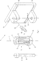
図1は、本発明に基づく装置の実施形態の分解斜視図を示し、
図2は、本発明に基づく装置の実施形態の断面を示している。
【0021】
図1に示される本発明に基づく装置1の実施形態は、ホルダ2と、ホルダ2内で移動可能な部材3と、移動可能な部材3をホルダ2内で案内する手段4とを有する。移動可能な部材3は、中心軸7およびこれと同軸に貫通する孔8を有する円筒6として形成されている。移動可能な部材3を案内する手段4は、装置内に取り外し可能に取りつけられる、孔8に挿通されるボルト9である。ボルト9の直径は、孔8へほとんどあそびなしに合わせられている。それによって、ホルダ2内で種々の移動可能な部材3が交換される場合でも、外科的な器具の正確な位置決めが保証される。移動可能な部材3は、多数の中空室5を有し、それらの中空室は中心軸7に対して、それぞれ該当する中空室5へ導入された外科用器具が、それぞれの中空室5のその器具に対応した形状によって装置1に対して正確に定められた位置および方位で収容されるように、形成されている。移動可能な部材3は、回転可能に軸承されている。それによって、移動可能な部材3が中心軸7を中心に回転することにより、種々の外科用器具のうちのそれぞれ1つが空間内で定められた位置へ移動されることが、可能にされる。
【0022】
移動可能な部材3の外側のジャケット面には、凹部10が形成されており、その凹部は中空室5に対して、ホルダ2に取り付けられたばね押圧部分11がこの凹部10の1つに嵌入することができ、それによって関連する中空室5を装置1の位置と方位に関して正確に定められた位置に取り外し可能に固定するように、対応している。ホルダ2には、6箇の発光ダイオードが取りつけられている。6箇の発光ダイオード(LED)12から放出された光波は、光学的な座標測定装置(図1には図示されていない)に属する少なくとも2つのセンサによって検出される。光学的なセンサによって受信された信号は、コンピュータ内で経過時間測定、干渉法またはビデオグラメトリーによって、測定値から装置1の正確な位置と方位を定めることができるように、処理される。コンピュータへの接続ケーブル13において、プラグ14内には装置1の位置と方位を格納する、消去可能な電子的データメモリ15が取り付けられている。ここに記載されている、本発明に基づく装置の実施形態においては、電子的なデータメモリ15は、消去可能でプログラム可能なリードオンリーメモリ(EPROM)である。
【0023】
図2に示す、本発明に基づく装置の実施形態は、図1に示す変形例とは、ボルト9と固定手段11の断面のみが異なっている。ボルト9は、移動可能な部材3に中心軸7に沿って完全に貫通して形成された孔8内に延びている。ボルト9の下方の端部22には、装置1のホルダ2内に固定するためのねじを備えた段部20が設けられている。ボルト9の上方の端部23には、ねじ形状のボルト9を螺合および脱合させるための手段が設けられている。これは、ローレット、ドライバー用のスリットまたは該当するドライバー用の内側六稜とすることができる。移動可能な部材3の外側のジャケット面には、凹部10が形成されている。凹部10は、同様に移動可能な部材3に設けられた、外科用器具を収容するための中空室5と関連している。ホルダ2の対応するねじ19へ螺合された固定手段11は、本発明に基づく装置の図示の実施形態においては、ばね押圧部分16である。このばね押圧部分16は、大体において円筒ねじと押圧ばね17と球18とからなる。球18とばね17は、円筒ねじ内に軸方向に圧縮可能に挿入されているので、球18は、ばね力によって凹部10内へ嵌入する。
【図面の簡単な説明】
【図1】 本発明に基づく装置の実施形態の分解斜視図を示している。
【図2】 本発明に基づく装置の実施形態の断面を示している。[0001]
(Technical field)
The present invention relates to an apparatus for calibrating and verifying the accuracy of a surgical instrument according to the superordinate concept of claim 1.
[0002]
(Background technology)
Three-dimensional images supported by this detection system since fundamental changes in medicine brought about by digitized image display (ultrasound technology, computer technology (CT scan), magnetic resonance image display (MRI)) Processing is increasingly being developed and is rooted in use in orthopedic surgery and dermatology. Three-dimensional images that display the surface and volume of bones and joints are easily adjusted by modern computers, giving surgeons an overview of how it looks during surgery with respect to bone or joint damage. Giving. This 3D system opens the way to surgical simulations, virtual manipulation of bone parts (virtual manipulation), anatomical modeling and prostheses adapted to bones and joints. The main field of application of 3D image processing technology is in image-guided navigation of surgical instruments in a patient during surgery and surgery prior to surgical intervention. Navigation during surgical procedures requires accurate detection of the position and orientation of the surgical instrument with respect to the stereoscopic reference system. Navigation during surgical intervention offers the following possibilities for users of this type of 3D system:
-Surgical instruments are displayed in real time on the monitor during surgery. The surgeon can always observe exactly where the instrument is at the time of the patient.
[0003]
The software module that forms the trajectory in real time indicates to the monitor the intended route for the instrument according to the current instrument orientation. It allows for precise positioning of the instrument without pre-surgical planning.
[0004]
The guidance software module allows the surgeon to compare the instrument route planned before surgery with the current position of the instrument and the route resulting from this current position and orientation of the instrument, in which case The planned route can be converted into an intraoperative instrument guide.
[0005]
In that case normal surgical instruments (drills, spoons, scissors, tweezers, sondes, etc.) can be used. In order to detect a position using a three-dimensional coordinate measurement system, the surgical instrument must be provided with a marker or sensor for outputting or receiving electromagnetic waves, sound waves or magnetic fields. This type of coordinate measurement system often has problems. In the case of ultrasonic measurements, this problem is based on the fact that an air medium is required for ultrasonic transmission. The physical properties of air vary in part very drastically with external parameters, temperature, pressure and air humidity. In order to be able to obtain the necessary data and thereby be able to continuously compensate for the deviations, the external parameters must always be measured. Otherwise, a relatively large error is introduced in the position determination. In the case of magnetic field measurements, again-a noisy magnetic field (for example based on a monitor, a computer or an electric motor); and-an impermeable substance in the magnetic field (for example a metal moved in the magnetic field),
External parameters such as (must always be measured).
Have proofreading accommodating portion for a surgical probe, apparatus having a fixedly alignable frame to surgical table is known from WO97 / 29683ACKER (Patent Document 1). This known device is a medical sonde with a fixed marker, a frame with a fixed marker that can be fixed to the patient, for example between a marker provided on the sonde and a marker provided on the frame. And a calculation unit for determining the relative position of the sonde with respect to the marker provided on the frame based on the detected magnetic field data. . The calibration housing provided on the frame guides the tip of the sonde into each calibration housing before using the sonde in the human body, so that the calibration housing is located between the known position of the calibration housing and the measured position of the sonde. Allows comparisons to be made.
The disadvantage of this known device is that the calibration housing can only be used for a single sonde.
[Patent Document 1]
WIPO International Bureau No. WO97 / 29683 ACKER
[0006]
(Disclosure of the Invention)
Here, the present invention seeks to provide a remedy. The object of the present invention is to inspect the calibration on the factory side in order to detect deformation or wear of the surgical instrument. In the case of a needle or drill, the various lengths of insertion must be confirmed.
[0007]
The invention solves the set problem by means of an apparatus for accurately calibrating and verifying the accuracy of a surgical instrument having the features of claim 1.
[0008]
In a preferred embodiment of the device according to the invention, the device comprises a freely positionable holder, a member which is supported in the holder and movable therein, and means for accurately guiding the movable member in the holder. Have. The movable member is provided with a number of hollow chambers that can be accurately aligned with the device. Each hollow chamber is shaped so that its shape corresponds exactly to a given surgical instrument. Therefore, the surgical instrument accommodated in the corresponding hollow chamber is accommodated at a position and orientation determined with respect to the apparatus. Guiding means that ensure accurate movement of the movable member within the holder can be removed from the holder to insert or remove the movable member. Thereby, the movable member can be exchanged for another movable member having another hollow chamber. A recess is formed in the outer jacket surface of each movable member, and means provided in the holder that fits into the recess fits into one of the recesses, thereby providing a corresponding hollow chamber of the device. The recess corresponds to the hollow chamber so as to be removably fixed at a position precisely defined with respect to position and orientation. The device is provided with six light emitting diodes (LEDs). Thereby, the position and orientation of the apparatus can be accurately obtained by the measuring apparatus. The measurement of the position and orientation of the device by means of electromagnetic waves emitted from the LEDs can be performed by means of elapsed time measurements, interference methods or videogrammetries. As the measuring device, for example, a three-dimensional movement measuring system OPTOTRAK 3020 of Northern Digital Inc., which is available on the market, can be considered. An erasable electronic data memory that stores the position and orientation of the device can be programmed into the computer software or included in the computer hardware.
[0009]
Another embodiment of the device according to the invention is that the only difference from the embodiment described above is that the movable member is a cylinder with a central axis and a through-hole coaxial therewith. As a means for guiding, a bolt that is detachably mounted in the apparatus and inserted through a hole formed through the movable member and the holder is used. The bolt is actually fitted into the hole without play, so that the movable member is moved about the central axis precisely here, corresponding to rotation. A screw is formed at one end of the bolt, and the screw can be screwed into a plate below the holder. The removable coupling of the bolt and the holder allows the exchange of movable members. The other end of the bolt is provided with means that allow the bolt to be easily screwed into and out of the device.
[0010]
Also, other embodiments of the apparatus according to the present invention are different from the above-described embodiments only in that the means for fitting into the recess formed in the movable member provided in the holder is a spring pressing portion. Is different. This spring pressing portion is screwed onto a screw formed corresponding to the holder. This generally consists of a cylindrical screw, a pressure spring and a ball or a pin tilted forward. Since the sphere or pin and the spring are inserted into the cylindrical screw so as to be compressible in the axial direction, the sphere or pin is fitted into the recess by the spring force.
[0011]
Other embodiments of the device according to the invention differ from the above-described embodiments only in that the means enabling the measurement device to determine the position and orientation of the device is a transmitter that emits electromagnetic waves. .
[0012]
Other embodiments of the device according to the invention differ from the variants described above only in that the means enabling the measurement device to determine the position and orientation of the device is an optical light source. Instead of an optical light source, of course, it is also possible to use a reflector, an infrared light emitting diode (IRED) or a fiber optic conductor that is energized by a light source in space.
[0013]
Other embodiments of the device according to the invention also differ from the variants described above by the fact that the measuring device operates on the basis of sound waves. A means attached to the device that allows the measuring device to determine the position and orientation of the device is a transmitter that emits sound waves.
[0014]
Another embodiment of the device according to the invention differs from that described above in that the means enabling the measuring device to determine the position and orientation of the device is a microphone.
[0015]
Other embodiments of the device according to the invention also differ from the variants described above by the fact that the measuring device operates on the basis of magnetic induction. The means attached to the device that allows the measuring device to determine the position and orientation of the device is an induction coil.
[0016]
Another embodiment of the device according to the invention differs from the variant described above in that the means enabling the measurement device to determine the position and orientation of the device is a Hall sensor.
[0017]
Other embodiments of the device according to the invention can be equipped according to any of the measurement methods described above with respect to position and orientation, but with the embodiments described above are erasable, storing the location and orientation of the device The electronic data memory is EPROM (Erasable Programmable Read-Only Memory), which differs depending on whether it is housed in a plug provided on the connection cable to the computer Yes.
[0018]
The advantages achieved by the present invention can be seen to a large extent in that various surgical instruments can be quickly calibrated with respect to their position and orientation in space by means of the device according to the invention. Thereby, the measurement error can be corrected immediately. This error correction can be considered at any time, even during surgery. Furthermore, the surgical instrument can be accurately calibrated with respect to position and orientation even if the instrument shape does not have a well-defined point or tip.
[0019]
The invention and the development of the invention are described in detail below using partial schematic representations of a number of embodiments.
[0020]
In that case:
FIG. 1 shows an exploded perspective view of an embodiment of the device according to the invention,
FIG. 2 shows a cross section of an embodiment of the device according to the invention.
[0021]
The embodiment of the device 1 according to the invention shown in FIG. 1 comprises a
[0022]
A
[0023]
The embodiment of the apparatus according to the invention shown in FIG. 2 differs from the variant shown in FIG. 1 only in the cross section of the
[Brief description of the drawings]
FIG. 1 shows an exploded perspective view of an embodiment of the device according to the invention.
FIG. 2 shows a cross section of an embodiment of the device according to the invention.
Claims (20)
A)前記装置(1)は、ホルダ(2)、前記ホルダ(2)内で移動可能な部材(3)および前記移動可能な部材(3)を前記ホルダ(2)内で案内する少なくとも1つの手段(4)を有し;
B)前記装置(1)に、空間内で前記ホルダ(2)の位置と方位を定めることを可能にする手段(12)が設けられており;
C)前記装置(1)に、前記ホルダ(2)の前記位置と方位を格納する、消去可能な電子的なメモリ手段(15)が設けられている、前記装置(1)であって、
D)前記移動可能な部材(3)には、前記ホルダ(2)に対して整合可能な幾つかの中空室(5)が設けられており、これら前記中空室(5)が幾つかの形状を有していて、この形状が幾つかの外科用器具に対応しており、そしてそれによって前記外科用器具を前記ホルダ(2)に対して正確に位置決めすることを可能にするように、前記中空室(5)が構成されていることを特徴とする、外科用器具の精度を正確に校正して検証する装置。In the device (1) for accurately calibrating and verifying the accuracy of surgical instruments,
A) said device (1) includes a holder (2), the holder (2) in a movable member (3) and said movable member (3) the holder (2) in at least one guiding in Having means (4);
In B) the device (1), and means (12) is provided that allows to determine the position and orientation of the holder in the space (2);
To C) the device (1), storing the position and orientation of the holder (2), erasable electronic memory means (15) is provided, a said device (1),
D) wherein the movable member (3), the holder (2) alignable several hollow chambers (5) are provided for, these said hollow chamber (5) with some features the have, so that this shape corresponds to the number of surgical instruments, and thereby makes it possible to accurately position the surgical instrument relative to the holder (2), wherein A device for accurately calibrating and verifying the accuracy of a surgical instrument, characterized in that a hollow chamber (5) is constructed.
Applications Claiming Priority (1)
| Application Number | Priority Date | Filing Date | Title |
|---|---|---|---|
| PCT/CH1998/000030 WO1999037232A1 (en) | 1998-01-27 | 1998-01-27 | Device for gauging and verifying the precision of surgical instruments |
Publications (3)
| Publication Number | Publication Date |
|---|---|
| JP2002500916A JP2002500916A (en) | 2002-01-15 |
| JP2002500916A5 JP2002500916A5 (en) | 2005-12-22 |
| JP4132006B2 true JP4132006B2 (en) | 2008-08-13 |
Family
ID=4551307
Family Applications (1)
| Application Number | Title | Priority Date | Filing Date |
|---|---|---|---|
| JP2000528223A Expired - Lifetime JP4132006B2 (en) | 1998-01-27 | 1998-01-27 | A device that calibrates and verifies the accuracy of surgical instruments |
Country Status (8)
| Country | Link |
|---|---|
| US (1) | US6347460B1 (en) |
| EP (1) | EP1051122B8 (en) |
| JP (1) | JP4132006B2 (en) |
| AT (1) | ATE228339T1 (en) |
| CA (1) | CA2314432C (en) |
| DE (1) | DE59806474D1 (en) |
| ES (1) | ES2186120T3 (en) |
| WO (1) | WO1999037232A1 (en) |
Families Citing this family (22)
| Publication number | Priority date | Publication date | Assignee | Title |
|---|---|---|---|---|
| US6206891B1 (en) * | 1999-09-14 | 2001-03-27 | Medeye Medical Technology Ltd. | Device and method for calibration of a stereotactic localization system |
| WO2001067979A1 (en) * | 2000-03-15 | 2001-09-20 | Orthosoft Inc. | Automatic calibration system for computer-aided surgical instruments |
| US6513259B1 (en) * | 2000-11-09 | 2003-02-04 | Chris D. Chiodo | Slide assembly with adjustable sliding resistance |
| JP2002207073A (en) * | 2001-01-11 | 2002-07-26 | Sony Corp | Information processing apparatus and method, and program |
| EP1364183B1 (en) * | 2001-01-30 | 2013-11-06 | Mako Surgical Corp. | Tool calibrator and tracker system |
| US7090639B2 (en) * | 2003-05-29 | 2006-08-15 | Biosense, Inc. | Ultrasound catheter calibration system |
| WO2005102202A1 (en) * | 2004-04-26 | 2005-11-03 | Orthosoft Inc. | Method for permanent calibration based on actual measurement |
| US7433023B2 (en) * | 2004-09-20 | 2008-10-07 | Applied Kinetics, Inc. | Apparatuses and methods for measuring head suspensions and head suspension assemblies |
| US8786613B2 (en) | 2006-04-08 | 2014-07-22 | Alan Millman | Method and system for interactive simulation of materials and models |
| US8395626B2 (en) * | 2006-04-08 | 2013-03-12 | Alan Millman | Method and system for interactive simulation of materials |
| US8560047B2 (en) * | 2006-06-16 | 2013-10-15 | Board Of Regents Of The University Of Nebraska | Method and apparatus for computer aided surgery |
| US8067726B2 (en) * | 2007-02-26 | 2011-11-29 | General Electric Company | Universal instrument calibration system and method of use |
| ITBO20070637A1 (en) * | 2007-09-19 | 2009-03-20 | Marposs Spa | EQUIPMENT AND METHOD FOR THE CONTROL OF PARTS OF A MECHANICAL PIECE |
| DE102007055456B4 (en) * | 2007-11-09 | 2010-04-22 | Aesculap Ag | Surgical referencing unit and surgical navigation system |
| WO2009076452A2 (en) * | 2007-12-10 | 2009-06-18 | Robotic Systems & Technologies, Inc. | Automated robotic system for handling surgical instruments |
| WO2010123879A1 (en) * | 2009-04-20 | 2010-10-28 | Virginia Tech Intellectual Properties, Inc. | Intramedullary nail targeting device |
| US9498231B2 (en) | 2011-06-27 | 2016-11-22 | Board Of Regents Of The University Of Nebraska | On-board tool tracking system and methods of computer assisted surgery |
| US11911117B2 (en) | 2011-06-27 | 2024-02-27 | Board Of Regents Of The University Of Nebraska | On-board tool tracking system and methods of computer assisted surgery |
| CA2840397A1 (en) | 2011-06-27 | 2013-04-11 | Board Of Regents Of The University Of Nebraska | On-board tool tracking system and methods of computer assisted surgery |
| US10105149B2 (en) | 2013-03-15 | 2018-10-23 | Board Of Regents Of The University Of Nebraska | On-board tool tracking system and methods of computer assisted surgery |
| DE102013214067A1 (en) * | 2013-07-17 | 2015-01-22 | Fiagon Gmbh | Device and method for connecting a medical instrument to a position detection system |
| US9730760B2 (en) * | 2015-09-30 | 2017-08-15 | Steven M Hacker | Electromagnetic resonant surgical scalpel handle and electromagnetic sensor system apparatus thereof |
Family Cites Families (12)
| Publication number | Priority date | Publication date | Assignee | Title |
|---|---|---|---|---|
| US4403860A (en) * | 1980-03-27 | 1983-09-13 | Diffracto Ltd. | Apparatus for determining dimensions |
| US4815218A (en) * | 1986-06-13 | 1989-03-28 | Cilco, Inc. | Gauge for calibrating surgical scalpel |
| US5323543A (en) * | 1992-09-29 | 1994-06-28 | Keratron Group | Apparatus and method for calibrating a surgical knife |
| US5483961A (en) * | 1993-03-19 | 1996-01-16 | Kelly; Patrick J. | Magnetic field digitizer for stereotactic surgery |
| US5768138A (en) * | 1994-06-29 | 1998-06-16 | Root Electro-Optics, Inc. | Automatic tooling inspection system |
| US5617857A (en) * | 1995-06-06 | 1997-04-08 | Image Guided Technologies, Inc. | Imaging system having interactive medical instruments and methods |
| SE506517C3 (en) * | 1995-06-19 | 1998-02-05 | Jan G Faeger | Procedure for saturating objects and apparatus for obtaining a set of objects with kaenda laegen |
| US5729475A (en) * | 1995-12-27 | 1998-03-17 | Romanik, Jr.; Carl J. | Optical system for accurate monitoring of the position and orientation of an object |
| EP0910299B1 (en) * | 1996-02-15 | 2003-02-12 | Biosense, Inc. | Method for configuring and operating a probe |
| IL125760A (en) * | 1996-02-15 | 2003-07-31 | Biosense Inc | Movable transmit or receive coils for location system |
| US5987960A (en) | 1997-09-26 | 1999-11-23 | Picker International, Inc. | Tool calibrator |
| US6253160B1 (en) * | 1999-01-15 | 2001-06-26 | Trimble Navigation Ltd. | Method and apparatus for calibrating a tool positioning mechanism on a mobile machine |
-
1998
- 1998-01-27 JP JP2000528223A patent/JP4132006B2/en not_active Expired - Lifetime
- 1998-01-27 CA CA002314432A patent/CA2314432C/en not_active Expired - Lifetime
- 1998-01-27 WO PCT/CH1998/000030 patent/WO1999037232A1/en not_active Ceased
- 1998-01-27 EP EP98900521A patent/EP1051122B8/en not_active Expired - Lifetime
- 1998-01-27 ES ES98900521T patent/ES2186120T3/en not_active Expired - Lifetime
- 1998-01-27 DE DE59806474T patent/DE59806474D1/en not_active Expired - Lifetime
- 1998-01-27 AT AT98900521T patent/ATE228339T1/en active
-
2000
- 2000-07-27 US US09/627,064 patent/US6347460B1/en not_active Expired - Lifetime
Also Published As
| Publication number | Publication date |
|---|---|
| HK1027954A1 (en) | 2001-02-02 |
| EP1051122A1 (en) | 2000-11-15 |
| CA2314432C (en) | 2006-10-10 |
| JP2002500916A (en) | 2002-01-15 |
| ATE228339T1 (en) | 2002-12-15 |
| ES2186120T3 (en) | 2003-05-01 |
| DE59806474D1 (en) | 2003-01-09 |
| EP1051122B8 (en) | 2003-01-15 |
| EP1051122B1 (en) | 2002-11-27 |
| CA2314432A1 (en) | 1999-07-29 |
| WO1999037232A1 (en) | 1999-07-29 |
| US6347460B1 (en) | 2002-02-19 |
Similar Documents
| Publication | Publication Date | Title |
|---|---|---|
| JP4132006B2 (en) | A device that calibrates and verifies the accuracy of surgical instruments | |
| US6112113A (en) | Image-guided surgery system | |
| JP4132009B2 (en) | Fiducial matching using fiducial screws | |
| US11219487B2 (en) | Shape sensing for orthopedic navigation | |
| US11793578B2 (en) | Optical shape sensing for instrument tracking in orthopedics | |
| JP4202434B2 (en) | Device for positioning and guiding in instrument application | |
| JP4201891B2 (en) | Tool calibration apparatus and method | |
| JP4153305B2 (en) | Instrument calibrator and tracking system | |
| US20050215888A1 (en) | Universal support arm and tracking array | |
| CA2467532C (en) | Detachable support arm for surgical navigation system reference array | |
| CN105813592B (en) | Surgical instrument and method for position detection of a surgical instrument | |
| US8821511B2 (en) | Instrument guide for use with a surgical navigation system | |
| JP6952696B2 (en) | Medical guidance device | |
| US20100312247A1 (en) | Tool attachment for medical applications | |
| US20050222793A1 (en) | Method and system for calibrating deformed instruments | |
| WO2010132985A1 (en) | Freehand ultrasound imaging systems and associated methods | |
| US12082884B2 (en) | Registration and identification tool and method for a dental and/or cranio-maxillofacial surgical instrument and/or general surgical instrument | |
| US11298207B2 (en) | Medical instrument identification | |
| HK1027954B (en) | Device for gauging and verifying the precision of surgical instruments | |
| US12251168B2 (en) | Systems, methods, and devices for localized tracking of a vertebral body or other anatomic structure | |
| GB2559175A (en) | Instrument guidance | |
| MXPA00011403A (en) | Fiducial matching by means of fiducial screws |
Legal Events
| Date | Code | Title | Description |
|---|---|---|---|
| A521 | Request for written amendment filed |
Free format text: JAPANESE INTERMEDIATE CODE: A523 Effective date: 20050121 |
|
| A621 | Written request for application examination |
Free format text: JAPANESE INTERMEDIATE CODE: A621 Effective date: 20050121 |
|
| TRDD | Decision of grant or rejection written | ||
| A01 | Written decision to grant a patent or to grant a registration (utility model) |
Free format text: JAPANESE INTERMEDIATE CODE: A01 Effective date: 20080514 |
|
| A01 | Written decision to grant a patent or to grant a registration (utility model) |
Free format text: JAPANESE INTERMEDIATE CODE: A01 |
|
| A61 | First payment of annual fees (during grant procedure) |
Free format text: JAPANESE INTERMEDIATE CODE: A61 Effective date: 20080530 |
|
| FPAY | Renewal fee payment (event date is renewal date of database) |
Free format text: PAYMENT UNTIL: 20110606 Year of fee payment: 3 |
|
| R150 | Certificate of patent or registration of utility model |
Free format text: JAPANESE INTERMEDIATE CODE: R150 |
|
| FPAY | Renewal fee payment (event date is renewal date of database) |
Free format text: PAYMENT UNTIL: 20110606 Year of fee payment: 3 |
|
| FPAY | Renewal fee payment (event date is renewal date of database) |
Free format text: PAYMENT UNTIL: 20120606 Year of fee payment: 4 |
|
| FPAY | Renewal fee payment (event date is renewal date of database) |
Free format text: PAYMENT UNTIL: 20120606 Year of fee payment: 4 |
|
| FPAY | Renewal fee payment (event date is renewal date of database) |
Free format text: PAYMENT UNTIL: 20130606 Year of fee payment: 5 |
|
| R250 | Receipt of annual fees |
Free format text: JAPANESE INTERMEDIATE CODE: R250 |
|
| R250 | Receipt of annual fees |
Free format text: JAPANESE INTERMEDIATE CODE: R250 |
|
| R250 | Receipt of annual fees |
Free format text: JAPANESE INTERMEDIATE CODE: R250 |
|
| R250 | Receipt of annual fees |
Free format text: JAPANESE INTERMEDIATE CODE: R250 |
|
| EXPY | Cancellation because of completion of term |