JP4128269B2 - Variable form turbine - Google Patents
Variable form turbine Download PDFInfo
- Publication number
- JP4128269B2 JP4128269B2 JP16268098A JP16268098A JP4128269B2 JP 4128269 B2 JP4128269 B2 JP 4128269B2 JP 16268098 A JP16268098 A JP 16268098A JP 16268098 A JP16268098 A JP 16268098A JP 4128269 B2 JP4128269 B2 JP 4128269B2
- Authority
- JP
- Japan
- Prior art keywords
- side wall
- spring
- variable form
- housing
- force
- Prior art date
- Legal status (The legal status is an assumption and is not a legal conclusion. Google has not performed a legal analysis and makes no representation as to the accuracy of the status listed.)
- Expired - Fee Related
Links
Images


Classifications
-
- F—MECHANICAL ENGINEERING; LIGHTING; HEATING; WEAPONS; BLASTING
- F01—MACHINES OR ENGINES IN GENERAL; ENGINE PLANTS IN GENERAL; STEAM ENGINES
- F01D—NON-POSITIVE DISPLACEMENT MACHINES OR ENGINES, e.g. STEAM TURBINES
- F01D17/00—Regulating or controlling by varying flow
- F01D17/10—Final actuators
- F01D17/12—Final actuators arranged in stator parts
- F01D17/14—Final actuators arranged in stator parts varying effective cross-sectional area of nozzles or guide conduits
- F01D17/141—Final actuators arranged in stator parts varying effective cross-sectional area of nozzles or guide conduits by means of shiftable members or valves obturating part of the flow path
- F01D17/143—Final actuators arranged in stator parts varying effective cross-sectional area of nozzles or guide conduits by means of shiftable members or valves obturating part of the flow path the shiftable member being a wall, or part thereof of a radial diffuser
Description
【0001】
【発明の属する技術分野】
本発明は、変位可能なタービン入口通路側壁を組込まれた可変形態タービンに関する。
【0002】
【従来の技術とその課題】
米国特許第5522697号公報には、タービンホイールがハウジング内の予め定められた軸線周りを回転するように装着された、公知の可変形態タービンが開示されている。タービンホイールに対する入口通路が、ハウジングの固定壁とこの固定壁に対して変位可能な側壁との間に画定され、これにより入口通路の幅が制御されるように構成されている。側壁は、ハウジングの回転軸線に平行して延在するロッド上に支持され、そしてこのロッドがハウジングに対し軸線方向へ移動され、これにより側壁を適用する位置が制御されれるように構成されている。
【0003】
ロッドは、ハウジングの外側に装着される空気圧アクチュエータで変位され、この空気圧アクチュエータはピストンを駆動する。アクチュエータピストンは、ハウジングに枢支される軸から延在するレバーに結合され、そしてこれによりレバーの変位を介して軸が回転される。2つの離間アームを備えたヨークが、ハウジング内部の凹部内の軸上に装着されている。ヨークの各アームの端縁部は、それぞれの側壁支持ロッド内のスロットに受入れられている。これにより、アクチュエータピストンが変位されると、アームが旋回され、側壁が軸方向へ駆動され、そしてこの結果アームと側壁支持ロッドとが相互係合される。
【0004】
この出願と同一優先日の同時係属出願にも可変形態タービンが開示されているが、これにおいては、側壁に対して機械的に結合される外部アクチュエータがハウジング内のピストン・シリンダ装置により変位されるように構成されている。側壁の軸方向位置の制御において、従来の前記外部アクチュエータ装置とおよびハウジング内ピストン・シリンダに依存する装置との双方に関して種々の問題がこれまでに経験されて来た。特に、この側壁が、その全閉位置−すなわち、タービン入口通路の幅が最少に近接される位置−へ接近される際に、その制御が困難となることが判明した。
【0005】
そこで、本発明の目的は、上述した問題を解決乃至軽減することにある。
【0006】
【発明の概要】
本発明によれば、以下のような可変形態タービン、すなわち、ハウジングと、ハウジング内の予め定められた軸線上を回転するよう装着されたタービンホイールと、固定壁および環状側壁の間に画定されるタービン用のガス入口通路であって、ハウジング内に装着されて、軸方向に離間された第一および第二の位置の間で固定壁に対し変位可能なガス入口通路と、側壁を固定壁から第一位置の方向へ向け離間するよう付勢する少なくとも1つのスプリングと、および側壁に対し軸方向の力を前記少なくとも1つのスプリングとは反対方向へ向け適用することにより側壁の軸方向位置を制御する手段とを含む可変形態タービンにおいて、前記少なくとも1つのスプリングがスプリング力に対し非線形の長さ特性を有し、これにより、適用されるスプリング力とおよび通路を通るガス流の結果側壁に適用される軸方向の力との合成力が、側壁が第一位置から第二位置へ変位するに従い連続的に増大されることを特徴とする可変形態タービンが提供される。
【0007】
側壁の変位に伴うスプリング力の変化率は、側壁が第一位置から第二位置へ変位するに従って増大されることができる。スプリング力は、1つまたはそれ以上のスプリングにより供給され、そして、そのまたはそれらの各々がスプリング力に対し非線形の長さ特性を有するように、或いは、2つまたはそれ以上のスプリングにより供給され、そして、それらの各々がスプリング力に対し線形の長さ特性を有するが、合成されたスプリング合成力は非線形となるように構成されることができる。
【0008】
側壁は、ホイールの軸線に平行して延在する支持ロッド上に装着されることができ、そしてこの支持ロッドは、そのまたはそれぞれのスプリングによって直接作用されるか、或いは、そのまたはそれぞれのスプリングを組込まれる外部アクチュエータに結合されることができる。
【0009】
【実施例】
次に、本発明の一実施態様を、実施例として、添付図面を参照しながら以下説明する。
【0010】
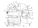
図1および図2を参照すると、図示される可変形態タービンは、環状クリップ3でクランプ結合された軸受ハウジング1およびタービンホイール・ハウジング2で画定されるハウジングと、軸線6周りを回転するよう軸5上に装着されるタービンホイール4とを含む。軸5は、軸受ハウジング1内の軸受上に支持されている。タービンハウジング2は、側壁9で画定される面8に対面する面7を画定する。図示される組立における側壁9は、比較的に薄い鋼材から全体的にC形状の断面に形成されているが、この側壁9は、例えば、鋳造部品から構成され得ることは理解されるであろう。側壁上に装着されるベーン10は、面8から、ハウジング内に画定された環状凹部11内へ突出されている。図示実施例におけるベーンを支持する側壁は、しばしば“ノズルリング”と呼称されているが、ここでは“側壁”と言う用語を使用する。
【0011】
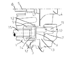
シールリング12が、面7および面8の間に画定される入口通路13と、側壁のベーン10から離間する側に位置するチャンバ14との間におけるガス流を規制している。すなわち、側壁9は、チャンバ14を画定している環状シリンダ内に受入れられる環状ピストンを形成している。側壁9が装着される支持ロッド15が、チャンバ14内に延在されている。入口16が、ハウジング14内の圧力を制御できるようにして軸受ハウジング1内に形成されている。圧力が増大すると、側壁9は、図1に示す全閉位置へ向け移動され、一方、圧力が減少すると、側壁9は、図2に示す全開位置へ向け移動される。
【0012】
図3を参照すると、ここには、軸受ハウジング1内におけるスプリング装着支持ロッド15に対する1つの装置が示されている。図3に示す装置−これは、全開位置における、図1および図2に示す側壁9に対応されている−において、各支持ロッドは、軸受ハウジング1内の孔部を貫通して凹部17内へ延在されている。凹部17は、軸受ハウジング1とこの軸受ハウジング1に結合される別のハウジング要素18との間に画定されている。凹部17内の圧力は大気圧に近似して維持されている。
【0013】
チャンバ14内の圧力は、側壁9の軸方向変位を制御するのに用いられる。チャンバ14内の圧力を制御する−例えば、エンジンの速度およびトルク、およびタービンの圧力および温度に対応した制御プログラムに従って−手段(図示せず)が設けられている。圧力制御手段は入口16に接続されている。
【0014】
ロッド15は、線形のスプリング力特性を有する圧縮スプリング19−これは、軸受ハウジング1とロッド15の一端縁部上に保持されるワッシャ20との間で圧縮されている−を介して、図3において左方向へ付勢されている。従って、若し入口通路13とチャンバ14とが大気に開放されていると、ロッド15は図3に示す軸方向の位置に位置されるであろう。次いで、若しチャンバ14内の圧力が増大されると、ロッド15と側壁9とは、適用された圧力に対応する距離だけ、図3において右側へ変位されるであろう。
【0015】
次に図4を参照すると、これは、本発明の一実施例を示し、そして、図3に示すと同等の要素には同一の参照符号が付されているが、しかしながら、この図4に示す装置では、更に別の圧縮スプリング21−軸線6と同一軸線を有する−が、環状支持リング22−図3に示す装置のワッシャ20と同一機能を果たす−に対接されていることが、注目されるであろう。各支持ロッド15は、また、同一軸線の圧縮スプリング19内を貫通して延在されている。従って、ロッド15を図4において左側へ駆動する力は、スプリング19および21によって適用される圧縮力と、入口通路13内を流動するガスによって側壁9に適用される軸方向力との合成力となる。
【0016】
スプリング19および21は、そのロッド15に適用される復帰力を、側壁9の面8がタービンハウジング2で画定される面7に近付く程増大されるように構成されている。例えば、スプリング21は、その弛緩時における長さを、側壁9が面7に比較的近接する場合を除き、リング22の図示右側への移動に対抗しないような長さに設定されることができる。このことは、入口通路13内の圧力−これは、面8上に作用される−が、面8が面7に近接する際に減少される−これら両面の間に画定される隙間内の流動条件のために−場合に、有利な特性となることが判明した。
【0017】
図5に、図3に関して説明したような装置−これでは、スプリング19は線形のスプリング率を有する−と、図4に示す本発明に係る装置−これでは、スプリング19および21の組み合わせは非線形のスプリング率を発生する−と、の間の作動的な相違を示す。図5において、曲線は、面7および面8間の間隔(入口通路の幅)が最少23(図1に示す全閉)から最大24(図2に示す全開)まで増大される際における、側壁9を含む要素組立に適用される軸方向の力を表している。
【0018】
図5の曲線25は、側壁9の面8上の反応ガスによる軸方向の力の変化を表している。通路幅が減少するに従い、反応ガス力は、最初は連続的に上昇するが次いで側壁9がタービンの面7に近付くに従い下降することが注目されるであろう。曲線26および27は、図3のスプリング19で適用される力を表している。曲線28および29は、側壁9上の合成軸方向力を表し、この合成力は、通路幅が線30で示される間隔を越えて減少するに従い減少されている。従って、図3に示す装置−これでは、スプリング19は線形の特性を有する−においては、入口通路幅が線30で表される限界まで減少すると、側壁9の軸方向位置が不安定となる。特に、側壁が線30で表される位置を通過するや否や、この側壁は最少幅の位置へ向け制御不能な状態で急速に移動される傾向を発生するであろう。
【0019】
図4に示す装置では、入口通路の幅が線24および25の間の間隔で表される範囲にある場合には、スプリング21は作用されない。しかしながら、通路幅が線31で表される限界まで減少されるや否や、通路幅のそれ以上の減少は、スプリング21およびスプリング19の双方を圧縮する。この結果、組み合わせスプリングの特性は線26および線32として表され、また合成力は線28および線33で表される。すなわち、スプリングおよび反応ガスの合成力は、入口通路幅が線23で表される最少幅まで減少されるにつれて連続的に増大される。従って、側壁9の軸方向位置の不安定性が解消される。
【0020】
図6を参照すると、これには、通常の構造−但し、線形の特性を有する通常の圧縮スプリングを非線形の特性を有する圧縮スプリングに変更したことを除いて−を有する外部アクチュエータ組立の断面図が示されている。図6に示すアクチュエータを図1乃至図4に示すような制御ロッドに相互連結する機構は、例えば米国特許第5522695号公報に開示されている。
【0021】
図6を参照して、この図の下半部は、全伸長状態におけるアクチュエータ(協働する側壁が、図1に示すように全閉されている位置に対応する)を示し、一方図6の上半部は、全収縮位置におけるアクチュエータ(協働する側壁が、図2に示すように全閉されている位置に対応する)を示している。アクチュエータは、鋼材のプレス要素35からなるカバーを有し、このカバーの間に、ダイアフラム36の周縁部がクランプされている。図6には、チャンバ37がダイアフラム36の左手側に図示されており、そしてこのチャンバ内に圧力ガスが入口(図示せず)から導入されることにより、カップ状部材39−この部材は、ダイアフラム36のチャンバ37から離間する側に対接されている−に連結されたアクチュエータ出力ロッド38の軸方向の移動が制御される。圧縮スプリング40がカバー内に受入れられ、そして、その一端部をピストン部材39に対接されると共に他端部をクランプ板41に対接されており、そして、このクランプ板からはスタッド42が延在され、このスタッドにはアクチュエータをサポート(図示せず)に固定するための適宜の手段が設けられている。塵埃シールド43は、汚染物質のカバー内への浸入を抑止している。
【0022】
通常のアクチュエータでは、圧縮スプリング40が長さ関係に対し線形のスプリング力を有するので、従って、図5において図3に示す構造を参照して説明したのと同様の制御問題が提起される。しかしながら、図6に示す本発明に係るアクチュエータでは、その圧縮スプリング40が非線形の特性を有することにより、図4に示すスプリング装置で発揮されるのと同等の性能が提供される。このような非線形のスプリング特性は、適宜通常の方法で、例えば、圧縮スプリング40を、その一方の端部スプリング巻回で他方の端部スプリング巻回の前に互いに接触されるように形成することにより、達成されることができる。別の装置、例えば、図6に示す円筒形よりはむしろ全体的に円錐形の圧縮スプリングを、企図し得ることは勿論である。
【0023】
更に、上述したように、本発明の代案としての実施態様では、2つまたはそれ以上のスプリング−これらのスプリングは、その各々はスプリング力に対して線形の長さ特性を有するが、合成されると非線形のスプリング力を発生するように構成されている−と協働されることができる。このようなスプリングの2つは、例えば、一方を他方の内部に収納するか、或いはこれらの端縁部同士を単一板のような適宜のサポートで分離して連結するように構成することができる。その他の可能な装置が、当業者には適宜容易に理解されるであろう。
【図面の簡単な説明】
【図1】可変形態タービンの側壁組立の上半部−但し、側壁はガス入口通路が最少幅となる位置に図示されている−を示す断面図である。
【図2】図1に示す側壁組立の下半部−但し、側壁は全開位置に変位されている−を示す断面図である。
【図3】図1および図2に示す側壁支持ロッドに対するスプリング装置を示す断面図である。
【図4】図1および図2に示す側壁支持ロッドに対する本発明に係るスプリング装置を示す断面図である。
【図5】図3および図4に示すスプリング組立の別の特性と、およびこのような組立を有する側壁上の反応ガス力および合成力とを示す略説明図である。
【図6】側壁支持ロッドに対する外部アクチュエータ組立−但し、アクチュエータは本発明に従い変更されている−を示す断面図である。
【符号の説明】
1 軸受ハウジング
2 タービンホイール・ハウジング
3 環状クリップ
4 タービンホイール
5 軸
6 軸線
7,8 面
9 側壁
10 ベーン
11 環状凹部
12 シールリング
13 入口通路
14 チャンバ
15 支持ロッド
16 入口
17 凹部
18 ハウジング要素
19,21 圧縮スプリング
20 ワッシャ
22 環状支持リング
23 最少間隔
24 最大間隔
25,26,27,28,29,32,33 曲線(線)
30,31 間隔
35 要素(カバー)
36 ダイアフラム
37 チャンバ
38 出力ロッド
39 カップ状部材(ピストン部材)
40 圧縮スプリング
41 クランプ板
42 スタッド
43 塵埃シールド[0001]
BACKGROUND OF THE INVENTION
The present invention relates to a variable geometry turbine incorporating a displaceable turbine inlet passage sidewall.
[0002]
[Prior art and its problems]
U.S. Pat. No. 5,522,697 discloses a known variable form turbine in which a turbine wheel is mounted for rotation about a predetermined axis in a housing. An inlet passage for the turbine wheel is defined between a fixed wall of the housing and a side wall that is displaceable relative to the fixed wall, whereby the width of the inlet passage is controlled. The side wall is supported on a rod that extends parallel to the axis of rotation of the housing, and the rod is configured to move axially relative to the housing, thereby controlling the position at which the side wall is applied. .
[0003]
The rod is displaced by a pneumatic actuator mounted on the outside of the housing, which drives the piston. The actuator piston is coupled to a lever that extends from a shaft that is pivotally supported by the housing, and thereby rotates the shaft through displacement of the lever. A yoke with two spaced arms is mounted on a shaft in a recess inside the housing. The edge of each arm of the yoke is received in a slot in the respective side wall support rod. Thus, when the actuator piston is displaced, the arm is pivoted, the side wall is driven in the axial direction, and as a result, the arm and the side wall support rod are engaged with each other.
[0004]
A variable form turbine is also disclosed in a co-pending application of the same priority date as this application, in which an external actuator mechanically coupled to the side wall is displaced by a piston and cylinder arrangement in the housing. It is configured as follows. Various problems have been experienced in the control of the axial position of the side wall, both with respect to the conventional external actuator device and with a device that relies on a piston and cylinder in the housing. In particular, it has been found that the side wall becomes difficult to control when it is approached to its fully closed position, i.e., the position where the width of the turbine inlet passage is minimized.
[0005]
Accordingly, an object of the present invention is to solve or reduce the above-described problems.
[0006]
SUMMARY OF THE INVENTION
In accordance with the present invention, the following variable form turbine is defined: a housing, a turbine wheel mounted for rotation on a predetermined axis in the housing, and a fixed wall and an annular side wall. A gas inlet passage for a turbine, mounted in the housing and displaceable relative to a fixed wall between first and second axially spaced positions, and a side wall from the fixed wall Controlling the axial position of the side wall by applying at least one spring biased away in the direction of the first position and applying an axial force against the side wall in a direction opposite to the at least one spring Wherein the at least one spring has a non-linear length characteristic with respect to the spring force and is thereby applied The combined force of the pulling force and the axial force applied to the side wall as a result of the gas flow through the passage is continuously increased as the side wall is displaced from the first position to the second position A variable form turbine is provided.
[0007]
The rate of change of the spring force associated with the displacement of the side wall can be increased as the side wall is displaced from the first position to the second position. The spring force is supplied by one or more springs, and each or each of them has a non-linear length characteristic with respect to the spring force, or is supplied by two or more springs, Each of them has a linear length characteristic with respect to the spring force, but the combined spring combined force can be configured to be non-linear.
[0008]
The side wall can be mounted on a support rod that extends parallel to the axis of the wheel, and this support rod is acted directly on by or on its or each spring. It can be coupled to an external actuator that is incorporated.
[0009]
【Example】
Next, one embodiment of the present invention will be described below as an example with reference to the accompanying drawings.
[0010]
Referring to FIGS. 1 and 2, the illustrated variable form turbine includes a housing defined by a bearing
[0011]
A
[0012]
Referring to FIG. 3, there is shown one device for the spring loaded
[0013]
The pressure in the
[0014]
The
[0015]
Reference is now made to FIG. 4, which shows an embodiment of the present invention, and elements equivalent to those shown in FIG. 3 are given the same reference numerals, however, as shown in FIG. It is noted that in the device, a
[0016]
The
[0017]
FIG. 5 shows a device as described with respect to FIG. 3—where the
[0018]
[0019]
In the apparatus shown in FIG. 4, the
[0020]
Referring to FIG. 6, this shows a cross-sectional view of an external actuator assembly having a conventional structure--except that a conventional compression spring having linear characteristics has been changed to a compression spring having non-linear characteristics. It is shown. A mechanism for interconnecting the actuator shown in FIG. 6 to a control rod as shown in FIGS. 1 to 4 is disclosed in, for example, US Pat. No. 5,522,695.
[0021]
Referring to FIG. 6, the lower half of this figure shows the actuator in its fully extended state (cooperating side walls correspond to the fully closed position as shown in FIG. 1), while FIG. The upper half shows the actuator in the fully retracted position (corresponding to the position where the cooperating side walls are fully closed as shown in FIG. 2). The actuator has a cover made of a
[0022]
In a normal actuator, the
[0023]
Further, as described above, in an alternative embodiment of the present invention, two or more springs—these springs are combined, each having a linear length characteristic with respect to the spring force. And configured to generate a non-linear spring force. Two of such springs can be configured, for example, such that one is housed inside the other, or these end edges are separated and connected by a suitable support such as a single plate. it can. Other possible devices will be readily understood by those skilled in the art as appropriate.
[Brief description of the drawings]
FIG. 1 is a cross-sectional view showing the upper half of a side wall assembly of a variable form turbine, where the side wall is shown in a position where the gas inlet passage is at its minimum width.
FIG. 2 is a cross-sectional view showing the lower half of the side wall assembly shown in FIG. 1—however, the side walls are displaced to the fully open position.
3 is a cross-sectional view showing a spring device for the side wall support rod shown in FIGS. 1 and 2. FIG.
4 is a cross-sectional view showing a spring device according to the present invention for the side wall support rod shown in FIGS. 1 and 2. FIG.
FIG. 5 is a schematic illustration showing another characteristic of the spring assembly shown in FIGS. 3 and 4 and the reactive and combined forces on the sidewall having such an assembly.
FIG. 6 is a cross-sectional view showing an external actuator assembly for a side wall support rod, where the actuator has been modified in accordance with the present invention.
[Explanation of symbols]
DESCRIPTION OF
30, 31 spacing 35 elements (cover)
36
40
Claims (7)
前記少なくとも1つのスプリングがスプリング力に対し非線形の長さ特性を有し、これにより、適用されるスプリング力とおよび通路を通るガス流の結果側壁に適用される軸方向の力との合成力が、側壁が第一位置から第二位置へ変位するに従い連続的に増大されることを特徴とする可変形態タービン。A gas inlet passage for a turbine defined between a housing, a turbine wheel mounted for rotation on a predetermined axis in the housing, and a fixed wall and an annular side wall, mounted in the housing A gas inlet passage displaceable relative to the fixed wall between first and second axially spaced positions and at least one biasing the side wall away from the fixed wall toward the first position A variable form turbine comprising: a spring; and means for controlling an axial position of the side wall by applying an axial force against the side wall in a direction opposite to the at least one spring.
The at least one spring has a non-linear length characteristic with respect to the spring force, whereby a combined force of the applied spring force and the axial force applied to the side wall as a result of gas flow through the passage. A variable form turbine characterized in that the sidewall is continuously increased as the side wall is displaced from the first position to the second position.
Applications Claiming Priority (2)
| Application Number | Priority Date | Filing Date | Title |
|---|---|---|---|
| GBGB9711892.1A GB9711892D0 (en) | 1997-06-10 | 1997-06-10 | Variable geometry turbine |
| GB9711892.1 | 1997-06-10 |
Publications (2)
| Publication Number | Publication Date |
|---|---|
| JPH1162511A JPH1162511A (en) | 1999-03-05 |
| JP4128269B2 true JP4128269B2 (en) | 2008-07-30 |
Family
ID=10813796
Family Applications (1)
| Application Number | Title | Priority Date | Filing Date |
|---|---|---|---|
| JP16268098A Expired - Fee Related JP4128269B2 (en) | 1997-06-10 | 1998-06-10 | Variable form turbine |
Country Status (4)
| Country | Link |
|---|---|
| EP (1) | EP0884454B1 (en) |
| JP (1) | JP4128269B2 (en) |
| DE (1) | DE69816373T2 (en) |
| GB (1) | GB9711892D0 (en) |
Families Citing this family (5)
| Publication number | Priority date | Publication date | Assignee | Title |
|---|---|---|---|---|
| DE19905637C1 (en) * | 1999-02-11 | 2000-08-31 | Daimler Chrysler Ag | Exhaust gas turbocharger for an internal combustion engine |
| US7475540B2 (en) | 2002-11-19 | 2009-01-13 | Holset Engineering Co., Limited | Variable geometry turbine |
| US6931849B2 (en) | 2002-11-19 | 2005-08-23 | Holset Engineering Company, Limited | Variable geometry turbine |
| US7207176B2 (en) | 2002-11-19 | 2007-04-24 | Cummins Inc. | Method of controlling the exhaust gas temperature for after-treatment systems on a diesel engine using a variable geometry turbine |
| GB2461720B (en) | 2008-07-10 | 2012-09-05 | Cummins Turbo Tech Ltd | A variable geometry turbine |
Family Cites Families (3)
| Publication number | Priority date | Publication date | Assignee | Title |
|---|---|---|---|---|
| DE2633587C2 (en) * | 1976-07-27 | 1985-05-23 | Klöckner-Humboldt-Deutz AG, 5000 Köln | Exhaust gas turbocharger for an internal combustion engine |
| CA1119140A (en) * | 1978-12-26 | 1982-03-02 | Phiroze Bandukwalla | Centrifugal vapor compressor and a diffuser control therefor |
| EP0654587B1 (en) | 1993-11-19 | 1999-01-20 | Holset Engineering Company Limited | Turbine with variable inlet geometry |
-
1997
- 1997-06-10 GB GBGB9711892.1A patent/GB9711892D0/en not_active Ceased
-
1998
- 1998-05-26 DE DE69816373T patent/DE69816373T2/en not_active Expired - Lifetime
- 1998-05-26 EP EP19980304122 patent/EP0884454B1/en not_active Expired - Lifetime
- 1998-06-10 JP JP16268098A patent/JP4128269B2/en not_active Expired - Fee Related
Also Published As
| Publication number | Publication date |
|---|---|
| GB9711892D0 (en) | 1997-08-06 |
| EP0884454B1 (en) | 2003-07-16 |
| DE69816373D1 (en) | 2003-08-21 |
| JPH1162511A (en) | 1999-03-05 |
| EP0884454A1 (en) | 1998-12-16 |
| DE69816373T2 (en) | 2004-04-15 |
Similar Documents
| Publication | Publication Date | Title |
|---|---|---|
| US6314736B1 (en) | Exhaust gas turbine of a turbocharger for an internal combustion engine | |
| US5044880A (en) | Variable geometry turbine actuator assembly | |
| KR960705132A (en) | TURBOCHARGER HAVING PNEUMATIC ACTUATOR WITH PILOT VALVE With Pneumatic Actuator With Pilot Valve | |
| US5941684A (en) | Variable geometry turbine | |
| JP4128269B2 (en) | Variable form turbine | |
| JPH0264203A (en) | Variable geometry turbine | |
| US6776574B1 (en) | Variable geometry turbine | |
| EP0342888B1 (en) | Variable geometry turbine inlet wall mounting assembly | |
| GB2108591A (en) | Casing of a gas turbine engine rotor | |
| JP2003515708A (en) | Membrane actuator | |
| JP2633144B2 (en) | Missile control fin actuator system | |
| JP4290991B2 (en) | Negative pressure actuator | |
| EP3628904B1 (en) | Jet-flapper servo valve | |
| JPH0711908A (en) | Flutter preventive device for steam turbine moving blade | |
| US10100851B2 (en) | Pneumatic actuator | |
| US5451780A (en) | Device for setting slit widths in the beam path of spectrometers | |
| JP2602909Y2 (en) | Turbocharger control device | |
| JPH0717900Y2 (en) | Gas cutoff valve with pilot valve mechanism | |
| JP2550712Y2 (en) | mechanical seal | |
| JP3469378B2 (en) | Electro-pneumatic converter | |
| JPS62255678A (en) | Full opening stopper for butterfly valve | |
| JPS6322381Y2 (en) | ||
| JP3288616B2 (en) | Gate valve | |
| JPH07293730A (en) | Fluid controller | |
| JPH08284980A (en) | Electric actuator and disk brake device |
Legal Events
| Date | Code | Title | Description |
|---|---|---|---|
| A521 | Written amendment |
Free format text: JAPANESE INTERMEDIATE CODE: A523 Effective date: 20050607 |
|
| A621 | Written request for application examination |
Free format text: JAPANESE INTERMEDIATE CODE: A621 Effective date: 20050607 |
|
| A977 | Report on retrieval |
Free format text: JAPANESE INTERMEDIATE CODE: A971007 Effective date: 20071129 |
|
| A131 | Notification of reasons for refusal |
Free format text: JAPANESE INTERMEDIATE CODE: A131 Effective date: 20071205 |
|
| A521 | Written amendment |
Free format text: JAPANESE INTERMEDIATE CODE: A523 Effective date: 20080305 |
|
| TRDD | Decision of grant or rejection written | ||
| A01 | Written decision to grant a patent or to grant a registration (utility model) |
Free format text: JAPANESE INTERMEDIATE CODE: A01 Effective date: 20080425 |
|
| A01 | Written decision to grant a patent or to grant a registration (utility model) |
Free format text: JAPANESE INTERMEDIATE CODE: A01 |
|
| A61 | First payment of annual fees (during grant procedure) |
Free format text: JAPANESE INTERMEDIATE CODE: A61 Effective date: 20080514 |
|
| FPAY | Renewal fee payment (event date is renewal date of database) |
Free format text: PAYMENT UNTIL: 20110523 Year of fee payment: 3 |
|
| R150 | Certificate of patent or registration of utility model |
Free format text: JAPANESE INTERMEDIATE CODE: R150 |
|
| FPAY | Renewal fee payment (event date is renewal date of database) |
Free format text: PAYMENT UNTIL: 20110523 Year of fee payment: 3 |
|
| FPAY | Renewal fee payment (event date is renewal date of database) |
Free format text: PAYMENT UNTIL: 20120523 Year of fee payment: 4 |
|
| FPAY | Renewal fee payment (event date is renewal date of database) |
Free format text: PAYMENT UNTIL: 20130523 Year of fee payment: 5 |
|
| R250 | Receipt of annual fees |
Free format text: JAPANESE INTERMEDIATE CODE: R250 |
|
| LAPS | Cancellation because of no payment of annual fees |