JP4127962B2 - Device for adjusting a stereotactic and endoscopically arranged appliance - Google Patents
Device for adjusting a stereotactic and endoscopically arranged appliance Download PDFInfo
- Publication number
- JP4127962B2 JP4127962B2 JP2000513519A JP2000513519A JP4127962B2 JP 4127962 B2 JP4127962 B2 JP 4127962B2 JP 2000513519 A JP2000513519 A JP 2000513519A JP 2000513519 A JP2000513519 A JP 2000513519A JP 4127962 B2 JP4127962 B2 JP 4127962B2
- Authority
- JP
- Japan
- Prior art keywords
- ball
- endoscopically
- adjusting
- stereotactically
- ring
- Prior art date
- Legal status (The legal status is an assumption and is not a legal conclusion. Google has not performed a legal analysis and makes no representation as to the accuracy of the status listed.)
- Expired - Fee Related
Links
- 210000003625 skull Anatomy 0.000 claims abstract description 38
- 238000000034 method Methods 0.000 claims abstract description 14
- 238000003780 insertion Methods 0.000 claims abstract description 6
- 230000037431 insertion Effects 0.000 claims abstract description 6
- 230000005855 radiation Effects 0.000 claims abstract description 5
- 239000011368 organic material Substances 0.000 claims abstract description 3
- 238000001574 biopsy Methods 0.000 claims description 11
- 230000033001 locomotion Effects 0.000 claims description 11
- 238000009434 installation Methods 0.000 claims description 7
- 239000003814 drug Substances 0.000 claims description 3
- 229940079593 drug Drugs 0.000 claims description 3
- 238000005553 drilling Methods 0.000 claims 1
- 239000008177 pharmaceutical agent Substances 0.000 abstract 2
- 210000004556 brain Anatomy 0.000 description 22
- 210000001951 dura mater Anatomy 0.000 description 3
- 206010000269 abscess Diseases 0.000 description 2
- 210000000988 bone and bone Anatomy 0.000 description 2
- 238000004364 calculation method Methods 0.000 description 2
- 208000031513 cyst Diseases 0.000 description 2
- 239000000463 material Substances 0.000 description 2
- 230000007246 mechanism Effects 0.000 description 2
- 230000008569 process Effects 0.000 description 2
- 239000000523 sample Substances 0.000 description 2
- 238000004088 simulation Methods 0.000 description 2
- 206010011732 Cyst Diseases 0.000 description 1
- 241001269524 Dura Species 0.000 description 1
- 208000018737 Parkinson disease Diseases 0.000 description 1
- 208000033809 Suppuration Diseases 0.000 description 1
- 230000009471 action Effects 0.000 description 1
- 238000013459 approach Methods 0.000 description 1
- 230000015572 biosynthetic process Effects 0.000 description 1
- 230000008859 change Effects 0.000 description 1
- 238000010276 construction Methods 0.000 description 1
- 238000011161 development Methods 0.000 description 1
- 230000000694 effects Effects 0.000 description 1
- 230000036512 infertility Effects 0.000 description 1
- 230000004807 localization Effects 0.000 description 1
- 238000004519 manufacturing process Methods 0.000 description 1
- 239000003550 marker Substances 0.000 description 1
- 238000012545 processing Methods 0.000 description 1
- 238000002672 stereotactic surgery Methods 0.000 description 1
- 230000003319 supportive effect Effects 0.000 description 1
- 238000001356 surgical procedure Methods 0.000 description 1
- 230000002861 ventricular Effects 0.000 description 1
Images
Classifications
-
- A—HUMAN NECESSITIES
- A61—MEDICAL OR VETERINARY SCIENCE; HYGIENE
- A61B—DIAGNOSIS; SURGERY; IDENTIFICATION
- A61B17/00—Surgical instruments, devices or methods, e.g. tourniquets
- A61B17/34—Trocars; Puncturing needles
- A61B17/3403—Needle locating or guiding means
-
- A—HUMAN NECESSITIES
- A61—MEDICAL OR VETERINARY SCIENCE; HYGIENE
- A61B—DIAGNOSIS; SURGERY; IDENTIFICATION
- A61B17/00—Surgical instruments, devices or methods, e.g. tourniquets
- A61B17/22—Implements for squeezing-off ulcers or the like on the inside of inner organs of the body; Implements for scraping-out cavities of body organs, e.g. bones; Calculus removers; Calculus smashing apparatus; Apparatus for removing obstructions in blood vessels, not otherwise provided for
- A61B2017/22082—Implements for squeezing-off ulcers or the like on the inside of inner organs of the body; Implements for scraping-out cavities of body organs, e.g. bones; Calculus removers; Calculus smashing apparatus; Apparatus for removing obstructions in blood vessels, not otherwise provided for after introduction of a substance
-
- A—HUMAN NECESSITIES
- A61—MEDICAL OR VETERINARY SCIENCE; HYGIENE
- A61B—DIAGNOSIS; SURGERY; IDENTIFICATION
- A61B17/00—Surgical instruments, devices or methods, e.g. tourniquets
- A61B17/34—Trocars; Puncturing needles
- A61B2017/348—Means for supporting the trocar against the body or retaining the trocar inside the body
- A61B2017/3482—Means for supporting the trocar against the body or retaining the trocar inside the body inside
- A61B2017/349—Trocar with thread on outside
-
- A—HUMAN NECESSITIES
- A61—MEDICAL OR VETERINARY SCIENCE; HYGIENE
- A61B—DIAGNOSIS; SURGERY; IDENTIFICATION
- A61B90/00—Instruments, implements or accessories specially adapted for surgery or diagnosis and not covered by any of the groups A61B1/00 - A61B50/00, e.g. for luxation treatment or for protecting wound edges
- A61B90/10—Instruments, implements or accessories specially adapted for surgery or diagnosis and not covered by any of the groups A61B1/00 - A61B50/00, e.g. for luxation treatment or for protecting wound edges for stereotaxic surgery, e.g. frame-based stereotaxis
- A61B2090/101—Instruments, implements or accessories specially adapted for surgery or diagnosis and not covered by any of the groups A61B1/00 - A61B50/00, e.g. for luxation treatment or for protecting wound edges for stereotaxic surgery, e.g. frame-based stereotaxis for stereotaxic radiosurgery
-
- A—HUMAN NECESSITIES
- A61—MEDICAL OR VETERINARY SCIENCE; HYGIENE
- A61B—DIAGNOSIS; SURGERY; IDENTIFICATION
- A61B90/00—Instruments, implements or accessories specially adapted for surgery or diagnosis and not covered by any of the groups A61B1/00 - A61B50/00, e.g. for luxation treatment or for protecting wound edges
- A61B90/10—Instruments, implements or accessories specially adapted for surgery or diagnosis and not covered by any of the groups A61B1/00 - A61B50/00, e.g. for luxation treatment or for protecting wound edges for stereotaxic surgery, e.g. frame-based stereotaxis
- A61B2090/103—Cranial plugs for access to brain
-
- A—HUMAN NECESSITIES
- A61—MEDICAL OR VETERINARY SCIENCE; HYGIENE
- A61B—DIAGNOSIS; SURGERY; IDENTIFICATION
- A61B90/00—Instruments, implements or accessories specially adapted for surgery or diagnosis and not covered by any of the groups A61B1/00 - A61B50/00, e.g. for luxation treatment or for protecting wound edges
- A61B90/10—Instruments, implements or accessories specially adapted for surgery or diagnosis and not covered by any of the groups A61B1/00 - A61B50/00, e.g. for luxation treatment or for protecting wound edges for stereotaxic surgery, e.g. frame-based stereotaxis
- A61B90/11—Instruments, implements or accessories specially adapted for surgery or diagnosis and not covered by any of the groups A61B1/00 - A61B50/00, e.g. for luxation treatment or for protecting wound edges for stereotaxic surgery, e.g. frame-based stereotaxis with guides for needles or instruments, e.g. arcuate slides or ball joints
Landscapes
- Health & Medical Sciences (AREA)
- Surgery (AREA)
- Life Sciences & Earth Sciences (AREA)
- Animal Behavior & Ethology (AREA)
- Public Health (AREA)
- Engineering & Computer Science (AREA)
- Biomedical Technology (AREA)
- Heart & Thoracic Surgery (AREA)
- Medical Informatics (AREA)
- Molecular Biology (AREA)
- Pathology (AREA)
- General Health & Medical Sciences (AREA)
- Nuclear Medicine, Radiotherapy & Molecular Imaging (AREA)
- Veterinary Medicine (AREA)
- Oral & Maxillofacial Surgery (AREA)
- Surgical Instruments (AREA)
- Radiation-Therapy Devices (AREA)
- Endoscopes (AREA)
- Magnetic Resonance Imaging Apparatus (AREA)
- Auxiliary Devices For And Details Of Packaging Control (AREA)
- Medical Preparation Storing Or Oral Administration Devices (AREA)
- Centrifugal Separators (AREA)
Abstract
Description
【0001】
本発明は、薬剤、放射線源及び有機材料を含む、種々の定位的且つ内視鏡的に配置される装具(equipment)の調整装置及び定位的且つ内視鏡的に配置される装具の調整方法に関する。
【0002】
本発明の請求項1の序文による装置はアメリカ特許第3115140号に開示されている。
【0003】
脳外科手順は、器具その他の補助具の正確な配置を必要とする場合、一般に以下の数段階で行なわれる。
1.患者にエックス線をかける。
2.患者の頭を、位置表示器を備えたフレーム(定位フレーム)に堅く捻り込む。
3.フレーム上のマーカーにより計算が行える個所に新たにエックス線をかけることにより、補助具を所望の領域に挿入可能とする。
4.患者を手術室に連れて行く。
【0004】
現今の装具での斯かる装備(instrumentation)を用いるための不可欠な条件は、患者の頭を定位設備に固定することである。フレームは、通常、ねじで頭蓋に取付けられる。次いで、頭部がアーム装置により、通常は手術台に固定される。
【0005】
アメリカ特許第4,955,891号は定位的外科手術を行う装置及び方法に関する。該方法は、頭蓋と頭蓋を配する支持表面との両方に固定された位置決め固定具間に第1の、所定の幾何学的関係を確立することにある。次いで、頭蓋を走査して、位置決め装置に対する頭蓋内の目標の像を提供する。これにより位置決め装置の少なくとも一部を幻像装置(phantom device)に移すことができ、幻像装置に対して位置決め装置を配置して第1の、所定の幾何学的位置関係に等しい第2の、所定の幾何学的関係を確立できる。頭蓋に取付けられた位置決め装置の傾斜が幻像装置内では倍増される。この手段により、幻像目標を頭蓋内の目標の位置に対応する位置に提供できる。これは、元々取付けられたのと同じ位置で頭蓋中の位置決め固定具部分から延びる医療器具への軌道と距離を計算することによって行う。計算は、位置決め装置に担持部材、弧状部材及び器具ガイド部材を設け、ガイド部材を介して医療器具を挿入することに基づいており、それにより医療器具は頭蓋に会してから、計算した所定深さで目標域に当たる。
【0006】
この方法を行うために、装具を、軌道ボールによって決まる軌道で位置決め固定具に通す。軌道ボールが内側に配されたボールホルダが頭蓋プレートに固定され、頭蓋プレートは頭蓋に固定される。ボールホルダは頭蓋プレートに対して回転可能である。しかしながら、この装置はいくつか欠点を有している。即ち、大きな操作面積が必要であり、幾つか緩んだ部品(頭蓋へ取付けるねじ)を用いる必要があり、そして、製造コストが高いので、小売価格が高い。ボール継手の中心が頭蓋外面より外に配置されるので、この医療器具の作用半径が極端に制限される(経路長手方向のみに制限される)。この設備はサイズが大きくて、種々の器具を使うのをより難しくするので、非実用的でもある。
【0007】
アメリカ特許第5,263,956号は神経外科で使用する装置に関する。ボール継手が、患者の頭蓋に対し神経外科ツールを所定方向に保持するよう構成されている。隅の尖った板を頭蓋に当接配置する。板の凹所にボール継手を配置する。ボール継手には中ぐり孔が通っていて、神経外科用装具を導入できる。ボールは回転可能であるため、頭蓋に対する神経外科探針の方向を調整できる。ねじを用い、板に対し神経外科探針を静止維持する。ボールホルダリングがボールを板に対し保持する。その装置は、幾つかの緩い部品(小ねじを含む)が構成されること、ボールを定位置に固定する機構がボール把持ねじであることを含む、使用上の幾つかの欠点を有する。これにより設備の扱いが難しくなり、ねじを紛失し易い。頭蓋にリングを固定する装置は、相対動を確実になくすのには充分でない。この装置の主な欠点は、ボールの中心点が頭蓋領域の外に位置するため、作用半径が厳しく制限されることである。
【0008】
アメリカ特許第4,681,103号は、外科器具の超音波調整用のガイド装置を開示している。装置は、装具を通す縦方向開口を有して頭蓋に堅く捻り込まれるアダプタハウジングで構成される。捻り込み用に、装置には把持面が備えられ、それが指で保持される。斯かる取付け機構であるため、アダプタハウジングの周りに殆ど余裕がない(例えば、肩付近及び頭後部)頭部の領域に装置を据付けるのが難しい。
【0009】
同時に、頭蓋の緻密な外骨層へ捻り込む際に充分な力を働かせるのが困難である。ボールの最適な位置が脳表面への当接部であるのは、ボールの中心を脳表面のより近くに配置すればする程、頭蓋の広い範囲に到達するのに必要な頭蓋開口が、より小さくて済むからである。アメリカ特許第4,681,103号に開示のアダプタハウジングでは、ハウジングの取付けねじ山の位置とソケット内のボールの位置は、ボールが前述の最適位置に位置しないようになっている。これに加え、ボール径は縦開口と同じサイズである。これらの特徴が組合わさって、この公知装置の使用時に得られる角度領域は60°より小である。その上、ボールをロックするのに幾つかの部品が必要であり、結果として信頼性が減少することになる。
【0010】
又、脳に対し特定の位置に装具を据付けるボール継手を使うことも公知である。この場合、柔らかな、即ち、しぼみ得るボールを用い、それがチューブを掴むことによりチューブの角度位置を確保する。しかしながら、これらの装置では、ボールに対しチューブを更に動かすことができない。従って、装具をボールに通す前にボールの角度位置を予め調整することができない。
【0011】
公知の解決策に関するこれら及びその他の問題は、本発明の装置によって解決される。本発明の装置は、ホルダと据付けキーとで構成され、ホルダが、ボール継手を形成するボールを配置する面を備えた下リングと、特定の位置にボールをロックする上リングとで構成され、ボールが医療器具挿入用の路を有し、下リングが患者の頭蓋領域に直接捻り込む外ねじ山面を有する。装置は、ボールの中央点が、従って、ボール継手の支点が、ボール当接部を形成するホルダの溝状部により、患者の頭蓋のレベルに位置するよう構成されたことを特徴としている。本発明は、
- 頭蓋上の点を局限し、
- 座金孔を造り、
- 形成された座金孔の壁に、ホルダの下リングをキーにより取付け、
- ボールの中央点が患者の頭蓋のレベルにあるようボールを下リングに配置し、
- ボールをロックすることなく上リングを下リングに取付け、
- 向きを調整するためにボールに定位ポインタを通し、
- 特定の角度位置にボールをロックし、
- 定位ポインタを、ドレーン、電極等の埋込み可能な装具、又は、内視鏡、生検針等の仮挿入可能な装具に取り替えること
から成ることを特徴とする、ホルダにより、薬剤を含む相異なる定位的且つ内視鏡的に配置される装具を調整する方法にも関する。本発明は、斯かる装置の、
- 生検採取、
- 嚢腫、膿瘍等の膨脹性突起での穿刺、
- 心室系の穿刺とドレーン及び装具の配置、
- マーカー、同位元素、及び、神経活性セル等の生化学的その他の材料の配置、
- 脳の記録/シミュレーションのための電極等の装具の配置
への適用にも関する。
【0012】
ホルダの下リングは、リングねじ山面を頭蓋の領域に捻り込み・外すのに用いられる据付けキーの突起と協働する溝を備えている。据付けキーを使用することには、大きな力を働かせて頭蓋の緻密な外骨層にリングを固定できる等、幾つかの利点がある。これに加えて、キーを使用すると、困難な領域へアクセスできる(キーは長くて幅狭で、据付けリングの周りに余分なスペースを必要としない)。装具は、ボール下部が脳硬膜(dura)表面のレベルにあるよう設計される。これにより、小さな座金孔を介し種々の脳構造に達する最良可能なアクセス可能性が確保される。
【0013】
ホルダの上リングは周にノッチを備え、その目的は上リングを下リングに固定する良好な把持部を得ることである。上下リングはいずれも傾斜面を備えているので、ボールを大きな角度範囲(ほぼ74°まで)に角度配置することができる。
【0014】
本発明のホルダは使用し易い。頭蓋への取付け複雑な器具を必要としない。ホルダは組立て易く、消毒し易い3つの部品のみで構成される。
【0015】
ボールがロックされていてもロックを外されていても、ボール内の路は変わらないので、路内にポインタを挿入する等して予めホルダの角度位置を調整し、角度位置を失うことなくポインタを取外し、外科器具を導入する。外科器具は角度位置のみ規制され、路内で依然として回転することができ、路の軸線方向に動かすこともできる。
【0016】
好適実施例では、ボールは、器具をボール内にガイドする、中央を延びるキャストインチューブを備え、チューブ径はボール径よりもかなり小さい。リングが傾斜平面を有することと相まって、これは、器具に、角度方向に広範囲な動きを持たせる助けとなる。好適実施例では、路は小断面の下部を有し、それにより(方向調節に用いられる)指向具がボールの赤道表面で止められ、後者が脳表面に当接又は脳表面の数ミリメートル上に配することが確保される。路が、小断面の下部を有しておらず、内部断面一定の場合には、上側にストッパを設け、ポインタ器具内の対応するストッパに当接させ、それにより、器具の深さ方向の動きを制限することができる。チューブはボールから周囲に突出しているので、器具のガイド効果が増加している。
【0017】
ボールの通し開口又はチューブで構成される、器具支持部が、器具のポイントを、その長さの大半に亙ってポイントのできるだけ先端近くまで囲む。
【0018】
ケーシング内をボールを介して通る挿入路がまさしく脳硬膜の表面で終わるので、全ての器具は可能な限り脳のところまでの支持が確保される。従って、器具の自由端は可能なかぎり短い。脳の表面から離れて配置される挿入システムに比べ、これによりナビゲーションエラーの危険が減少する。
【0019】
使用時に、ホルダには、例えば、チューブ内側に生検針を備えたアダプタを更に供給することができる。アダプタは外部的には、ボールに接続された挿入スリーブの内径に適合しており、内部的には、使用しなければならない器具の周に適合している。2つのロック/ストッパが、脳に挿入しなければならない器具(例えば、生検針)に沿って正しい長さで取付けられる。これらのロックは、個々の器具に合わせたアダプタ頂部のカラーに当接する。この手段により、装具は予定より深く脳に挿入されるのが防がれる。
【0020】
好適実施例では、チューブとアダプタとが、異なる装具に接続する同一手段で構成される。
【0021】
挿入しなければならない器具とちょうど同じ位の大きさの孔を脳硬膜に開けることで充分なので、最適の滅菌性が保証される。脳硬膜に大きな孔を開けると脳表面が多少崩れるが、これも本発明を用いることにより排除できる。
【0022】
装具は、皮膚を通って突出しなければならない電極等の装具を脳内に配置後に、取外すのが容易となるように設計されている。底部リングを捻り外すため、長めの線又はドレーンを仮に挿入し、据付けキーに穿設した路(図示せず)を介し突出することができる。これは、好適実施例では本発明の方法が以下の更なる段階から成ることを意味する。
- ホルダの上リングを取外すこと、
- ボールを取外すこと、
- 埋込み可能/仮導入可能な装具をキーへと、その内部路を介して、挿入すること、
- ホルダの下リングを取外すこと、
- 装具を患者内の所定位置に残したままキーから埋込み可能な/仮導入可能な装具を除去すること。
【0023】
又、本発明の装置では、ボールがボール継手の動きの限界位置にあっても、ボールをほぼ平行に取外すことができる。
【0024】
本発明の装置は広い適用範囲を有する。本発明の装置はとりわけ以下で使用できる。
a)生検採取、
b)とりわけ、嚢腫、膿瘍(膿形成部)等の膨脹性突起の穿刺、
c)心室系の穿刺とドレーン及び装具(内視鏡)の配置、
d)(後で放射又は外科的処置を行うための)マーカー、(局部的放射のための)同位元素及び生化学的等の材料(パーキンソン病等の治療のための神経活性セル等)の配置、
e)脳の記録/シミュレーションのための電極等の装具の配置。
【0025】
本発明による装置と方法は、その他には、添付の特許請求項に示した特徴により特徴付けられる。
【0026】
ホルダの適用例に関連して、添付図面に関し、装置を更に詳細に記述する。
【0027】
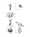
図1は、分解した位置での本発明の装置を示す。装置を構成するホルダが有する下リング1は、ボール2を置く面(溝)4と、据付けキー7の突起6に協働するノッチ5と、2つの外ねじ山面9,8を有する。第1の外ねじ山面9の上部が下リング1上に位置し、上リング3と協働してボール2をロックする。第2の外ねじ山面8の底部は下リング1内に位置しているので、下リング1を頭蓋に取付けできる。下リング1には、ボール2当接部を形成する溝状部22が更に設けられている。
【0028】
ボール継手を形成するボール2には医療器具挿入用の通し路10が備えられている。好適実施例によれば、ボールにはキャストイン(cast-in)チューブ11が備えられ、それが医療器具をボール2内にガイドする。更なる好適実施例によれば、キャストインチューブ11は好ましくは小断面で装具調整に用いる器具の動きを制限する下部12を有する。これらの器具はキャストインチューブ11の下部12よりも大径な部分を有するので、キャストインチューブ11がそれらよりも幅広である領域での縦方向動きが制限される。これにより、調整器具が脳に接触しないことが確保される。ホルダの上リング3は、ボール2の頂部を囲む下縁13と、下リング1の上外ねじ山部9と協働する内ねじ山部14を備えている。ボール2は自由に回転させることができ、円錐動させることができる。上リング3は周にノッチ16を有しており、その目的はボール2の周りにリング1,3を相互取付けするための良好な把持部を得ることである。上リング3は上円錐開口15を備えており、その目的は器具の最高可能な運動範囲を確保することである。図1には生検針のアダプタ17及びストッパ18も示されている。
【0029】
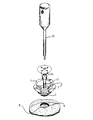
図2は組立て位置での装置を示す。図2に示した頭蓋の開口Aには、下リング1の下ねじ山面8を取付けねばならない。図2は脳表面Bのすぐ近くにボール2を配することを示している。
【0030】
本発明による装置により装具を調整する方法を図面に関して以下説明する。それは、なかんずく以下の段階から成る。
- 指向具により、調べねばならない領域へのアプローチとして選ばれる頭蓋上の点を局限する。
- 座金孔(図2の開口A)を従来の「ボールドリル」(Aesculap、径=16mm)で造る。
-形成した座金孔Aの壁に下リング1の面を、突起6を有する据付けキー7で捻り込み、下リング1のノッチ5が突起6に合う。据付けキー7は中心を延びる溝を有していても良い(図示せず)。
- ボール2を溝4内に配置する。
- 頭蓋内に取付けた上下リング3,1を捻り合わせて、ボール2をそれぞれ下溝22と上溝13との間に保持し、最良可能な安定性と運動範囲を確保するためにボール2を頭蓋の方へできるだけ下げて取付け、それにより最良可能な精度と調節可能性を提供する。
- ボール2が上下リング3,1間でロックされない限り、チューブ11は自由に操作でき、回転できる。装具が円筒形でない場合、ホルダでは、装具がアダプタ17とチューブ11の間の動き及びボール継手2内の動きによって回転でき、それにより随意の切断平面を検討する可能性を提供する。
- 定位ポインタ19をチューブ11に挿入し、ポインタ先端がボール2の最末端の赤道平面に触れて停止する。何故なら、チューブ11の下部12がチューブ11の他の部分よりも小径だからである。
- チューブ11の方向を調節し、検査/操作を行う領域への深さを決める。
- ボール2は上リング3を摘むことによってロックし、上下リング3,1がボール2を囲む。
- 定位ポインタ19を引抜いて脇にやり、全ての不要な装具(柔らかな部分を別に固定するホルダを含む)は、器具を脳に挿入する前に取除く(これにより、以降の処理の最良の作業条件が確保される)。
- チューブ11に通さねばならない装具に特に合わせたアダプタ17を定位置に置き、好ましくはアダプタの端ピース20を緑色に着色し、チューブ11の上方、例えば5mmに突出させる。
- アダプタ17を通る装具は、ストッパ18がアダプタの端ピース20に当たって止まると、止まる。
- 脳内での目標領域への距離を読取る。
- チューブ11とアダプタ17の長さ(例えば、45mm+5mm=50mm)を加える。
- リングクランプ18を、生検針等の器具(図示せず)に取付け、それにより正しい深さで止める。
【0031】
生検針システムは、最大限の安全のためにヒンジ(hinged)リングクランプ18を2つ有するのが好ましい(図では1つだけ示している)。
【0032】
本発明の好適実施例では、チューブ11の頂部を、定位ポインタ19以外の装具を挿入しないよう警告として赤色に着色する。
【0033】
上記した本発明は、多目的に使用できる万能装置を呈する。
【0034】
以上述べてきたことに加え、本装置を例えば脳内を動かす装具のホルダ及び支持部として用いることもできる。ボール継手に取付けることにより、頭蓋下の脳構造の動きを可能な最小限とすることが確保される。このようにして、生体の脳構造を不必要な動き、応力及び損傷から保護するよう注意が払われる。これらの適用範囲は、添付の特許請求の範囲に示された如き本発明の範囲から逸脱することなく含まれる。
【図面の簡単な説明】
【図1】 分解位置での本発明の装置の展開図であり、素子の相対位置及び生検針のアダプタとストッパを示す。
【図2】 組立て位置での本発明の装置、及び、ホルダと共に使用する器具の展開図である。[0001]
The present invention relates to a device for adjusting various stereotactically and endoscopically arranged appliances including a drug, a radiation source and an organic material, and a method for adjusting a stereotactically and endoscopically arranged appliance. About.
[0002]
An apparatus according to the preamble of
[0003]
A neurosurgical procedure is generally performed in several stages when precise placement of instruments and other aids is required.
1. X-ray the patient.
2. The patient's head is tightly twisted into a frame (positioning frame) with a position indicator.
3. An auxiliary tool can be inserted into a desired region by newly applying an X-ray to a place where calculation can be performed using a marker on the frame.
4). Take the patient to the operating room.
[0004]
An essential condition for using such instrumentation in modern appliances is to secure the patient's head to a stereotaxic facility. The frame is usually attached to the skull with screws. The head is then typically secured to the operating table by an arm device.
[0005]
U.S. Pat. No. 4,955,891 relates to an apparatus and method for performing stereotactic surgery. The method consists in establishing a first, predetermined geometric relationship between positioning fixtures secured to both the skull and the support surface on which the skull is placed. The skull is then scanned to provide an image of the target within the skull for the positioning device. This allows at least a portion of the positioning device to be transferred to the phantom device, where the positioning device is positioned relative to the phantom device and a second, predetermined, equal to a first, predetermined geometric positional relationship. Can be established. The tilt of the positioning device attached to the skull is doubled in the phantom device. By this means, the phantom target can be provided at a position corresponding to the position of the target in the cranium. This is done by calculating the trajectory and distance to the medical device that extends from the positioning fixture portion in the skull at the same location it was originally attached. The calculation is based on providing the positioning device with a carrier member, an arcuate member and an instrument guide member, and inserting the medical instrument through the guide member, so that the medical instrument meets the skull and then calculates the predetermined depth. Now hit the target area.
[0006]
To perform this method, the brace is passed through the positioning fixture in a track determined by the track ball. A ball holder with an orbiting ball arranged inside is fixed to the skull plate, and the skull plate is fixed to the skull. The ball holder is rotatable with respect to the skull plate. However, this device has several drawbacks. That is, a large operating area is required, several loose parts (screws attached to the skull) need to be used, and the manufacturing cost is high, so the retail price is high. Since the center of the ball joint is disposed outside the outer surface of the skull, the working radius of the medical device is extremely limited (limited only in the longitudinal direction of the path). This equipment is also impractical because it is large in size and makes it more difficult to use various instruments.
[0007]
U.S. Pat. No. 5,263,956 relates to a device for use in neurosurgery. A ball joint is configured to hold the neurosurgical tool in a predetermined orientation relative to the patient's skull. A plate with a sharp corner is placed in contact with the skull. Place the ball joint in the recess of the plate. The ball joint has a bore hole through which a neurosurgical instrument can be introduced. Since the ball is rotatable, the orientation of the neurosurgical probe relative to the skull can be adjusted. Using a screw, keep the neurosurgical probe stationary against the plate. A ball holder ring holds the ball against the plate. The device has several disadvantages in use, including the construction of several loose parts (including machine screws) and the mechanism for securing the ball in place is a ball gripping screw. This makes it difficult to handle the equipment and makes it easy to lose screws. Devices that secure the ring to the cranium are not sufficient to reliably eliminate relative movement. The main drawback of this device is that the radius of action is severely limited because the center point of the ball is located outside the skull region.
[0008]
U.S. Pat. No. 4,681,103 discloses a guide device for ultrasonic adjustment of a surgical instrument. The device consists of an adapter housing that has a longitudinal opening through which the brace is passed and is tightly twisted into the skull. For twisting, the device is provided with a gripping surface, which is held by a finger. Because of such an attachment mechanism, it is difficult to install the device in the region of the head with little room around the adapter housing (eg, near the shoulder and back of the head).
[0009]
At the same time, it is difficult to exert sufficient force when twisting into the dense outer bone layer of the skull. The optimal position of the ball is the abutment with the brain surface. The closer the center of the ball is to the brain surface, the more the cranial opening necessary to reach a wider area of the skull. This is because it can be small. In the adapter housing disclosed in U.S. Pat. No. 4,681,103, the position of the mounting screw of the housing and the position of the ball in the socket are such that the ball is not located at the optimum position described above. In addition, the ball diameter is the same size as the vertical opening. Combined with these features, the angular range obtained when using this known device is less than 60 °. Moreover, several parts are required to lock the ball, resulting in reduced reliability.
[0010]
It is also known to use a ball joint that installs the brace at a specific position relative to the brain. In this case, a soft or squeezable ball is used, which secures the angular position of the tube by gripping the tube. However, these devices do not allow the tube to move further relative to the ball. Therefore, the angular position of the ball cannot be adjusted in advance before passing the brace through the ball.
[0011]
These and other problems with known solutions are solved by the apparatus of the present invention. The apparatus of the present invention is composed of a holder and an installation key, and the holder is composed of a lower ring having a surface on which a ball forming a ball joint is arranged, and an upper ring that locks the ball in a specific position, The ball has a path for insertion of a medical device and the lower ring has an external thread surface that twists directly into the patient's skull area. The device is characterized in that the center point of the ball and thus the fulcrum of the ball joint is arranged at the level of the patient's skull by the groove of the holder forming the ball abutment. The present invention
-Localize points on the skull,
-Build a washer hole
-Attach the lower ring of the holder to the wall of the formed washer hole with the key,
-Place the ball on the lower ring so that the center point of the ball is at the level of the patient's skull,
-Mount the upper ring on the lower ring without locking the ball,
-Pass the stereo pointer over the ball to adjust the orientation,
-Lock the ball at a certain angular position,
-Different localizations, including drugs, by holders, characterized by comprising replacing the stereotactic pointer with implantable devices such as drains, electrodes, or temporarily insertable devices such as endoscopes, biopsy needles, etc. The invention also relates to a method for adjusting an orthopedically placed appliance. The present invention relates to such a device.
-Biopsy collection,
-Puncture with bulging process such as cyst, abscess,
-Ventricular puncture and drain and appliance placement,
-Placement of markers, isotopes, and other biochemical materials such as neuroactive cells,
-Also related to the placement of devices such as electrodes for brain recording / simulation.
[0012]
The lower ring of the holder is provided with a groove that cooperates with the projection of the installation key used to twist and unscrew the ring thread surface into the region of the skull. Using a stationary key has several advantages, such as the ability to apply great force to fix the ring to the dense outer bone layer of the skull. In addition, the key allows access to difficult areas (the key is long and narrow and does not require extra space around the mounting ring). The brace is designed so that the lower part of the ball is at the level of the dura surface. This ensures the best possible accessibility to reach various brain structures via small washer holes.
[0013]
The upper ring of the holder is provided with a notch in the circumference, the purpose of which is to obtain a good gripping part for fixing the upper ring to the lower ring. Since both the upper and lower rings have inclined surfaces, the ball can be angularly arranged in a large angle range (up to approximately 74 °).
[0014]
The holder of the present invention is easy to use. Mounting to the skull does not require complicated instruments. The holder is composed of only three parts that are easy to assemble and easy to disinfect.
[0015]
Regardless of whether the ball is locked or unlocked, the path in the ball will not change, so you can adjust the angular position of the holder in advance by inserting a pointer into the path, etc. Remove and introduce surgical instruments. The surgical instrument is constrained only in angular position, can still rotate in the path, and can be moved in the axial direction of the path.
[0016]
In a preferred embodiment, the ball comprises a centrally extending cast-in tube that guides the instrument into the ball, the tube diameter being much smaller than the ball diameter. Coupled with the fact that the ring has an inclined plane, this helps the instrument to have a wide range of angular movement. In the preferred embodiment, the path has a small cross-sectional bottom so that the directional tool (used for orientation) is stopped at the equator surface of the ball, the latter abutting the brain surface or a few millimeters above the brain surface It is ensured to distribute. If the path does not have a small cross-section lower part and the internal cross-section is constant, a stopper is provided on the upper side to abut against the corresponding stopper in the pointer instrument, thereby moving the instrument in the depth direction Can be limited. Since the tube protrudes from the ball to the periphery, the guiding effect of the instrument is increased.
[0017]
An instrument support, consisting of a ball opening or tube, surrounds the instrument point as close as possible to the tip of the point over most of its length.
[0018]
Since the insertion path through the ball through the ball ends at the very surface of the dura mater, all instruments are as supportive as possible to the brain. The free end of the instrument is therefore as short as possible. This reduces the risk of navigation errors compared to insertion systems that are located away from the surface of the brain.
[0019]
In use, the holder can be further supplied with an adapter with a biopsy needle inside the tube, for example. The adapter is externally adapted to the inner diameter of the insertion sleeve connected to the ball and internally adapted to the circumference of the instrument that must be used. Two locks / stoppers are attached at the correct length along the instrument (eg, a biopsy needle) that must be inserted into the brain. These locks abut against the collar on the top of the adapter tailored to the individual instrument. This measure prevents the brace from being inserted deeper into the brain than planned.
[0020]
In the preferred embodiment, the tube and adapter are constructed of the same means for connecting to different appliances.
[0021]
Optimal sterility is ensured because it is sufficient to make a hole in the dura mater that is just as large as the instrument that must be inserted. When a large hole is made in the brain dura mater, the surface of the brain is somewhat broken, but this can also be eliminated by using the present invention.
[0022]
The braces are designed to be easy to remove after placing braces such as electrodes that must protrude through the skin into the brain. To twist off the bottom ring, a long wire or drain can be temporarily inserted and protruded through a path (not shown) drilled in the installation key. This means that in a preferred embodiment the method of the invention consists of the following further steps:
-Removing the upper ring of the holder,
-Removing the ball,
-Inserting an implantable / temporary introducer into the key via its internal channel,
-Removing the lower ring of the holder,
-Removing the implantable / temporary introducer from the key while leaving the brace in place in the patient.
[0023]
Further, in the apparatus of the present invention, even when the ball is at the limit position of the ball joint, the ball can be removed almost in parallel.
[0024]
The device of the present invention has a wide range of applications. The device according to the invention can be used inter alia in the following.
a) biopsy collection,
b) punctures of inflatable processes such as cysts, abscesses (pus formation parts),
c) Ventricular puncture and placement of drain and appliance (endoscope),
d) Placement of markers (for later radiation or surgical treatment), isotopes (for local radiation) and biochemical materials (such as neuroactive cells for the treatment of Parkinson's disease, etc.) ,
e) Arrangement of devices such as electrodes for brain recording / simulation.
[0025]
The apparatus and method according to the invention are otherwise characterized by the features indicated in the appended claims.
[0026]
In connection with the application example of the holder, the device will be described in more detail with reference to the accompanying drawings.
[0027]
FIG. 1 shows the device of the present invention in an exploded position. The
[0028]
The
[0029]
FIG. 2 shows the device in the assembled position. A
[0030]
A method for adjusting the brace with the device according to the invention will now be described with reference to the drawings. It consists of the following stages:
-The pointing tool localizes the point on the skull that is chosen as the approach to the area that must be examined.
-A washer hole (opening A in FIG. 2) is made with a conventional “ball drill” (Aesculap, diameter = 16 mm).
-The surface of the
-Place the
-Twist the upper and
-As long as the
-The
-Adjust the direction of the
-The
-Pull out the
The
-The brace that passes through the
-Read the distance to the target area in the brain.
-Add the length of the
-Attach the
[0031]
The biopsy needle system preferably has two hinged ring clamps 18 for maximum safety (only one is shown in the figure).
[0032]
In the preferred embodiment of the present invention, the top of the
[0033]
The present invention described above presents a universal device that can be used for multiple purposes.
[0034]
In addition to what has been described above, the present apparatus can also be used as a holder and a support part of a brace that moves in the brain, for example. By attaching to the ball joint, it is ensured that the movement of the subcranial brain structure is minimized. In this way, care is taken to protect the biological brain structure from unnecessary movement, stress and damage. These scopes are included without departing from the scope of the present invention as set forth in the appended claims.
[Brief description of the drawings]
FIG. 1 is a development view of the device of the present invention in an exploded position, showing the relative position of the elements and the biopsy needle adapter and stopper.
FIG. 2 is an exploded view of the device of the present invention and the instrument for use with the holder in the assembled position.
Claims (13)
ボール(2)が、ボール(2)を通る医療器具をガイドする、中央を延びるキャストインチューブ(11)を備え、キャストインチューブ(11)がボール表面から周囲に突出していることを特徴とする、定位的且つ内視鏡的に配置される装具を調整する装置。A lower ring (1) having a surface (4) on which a ball (2) forming a ball joint is arranged, and an upper ring (3) for locking the ball in a specific position. Configured, the ball (2) has a medical instrument insertion path (10), the lower ring (1) has an external thread surface (8) for direct twisting into the patient's skull, and the ball (2) Drug, radiation source, so that the central point of the ball joint, and therefore the fulcrum of the ball joint, is located at the level of the patient's skull by the groove (22) of the holder forming the ball (2) abutment And a device for adjusting a stereotactically and endoscopically disposed appliance comprising an organic material,
The ball (2) is provided with a cast-in tube (11) extending centrally for guiding a medical device passing through the ball (2), the cast-in tube (11) protruding from the ball surface to the periphery. A device that adjusts a stereotactically and endoscopically arranged appliance.
Applications Claiming Priority (3)
| Application Number | Priority Date | Filing Date | Title |
|---|---|---|---|
| NO974274A NO974274L (en) | 1997-09-16 | 1997-09-16 | Holder for sterotactic equipment |
| NO974274 | 1997-09-16 | ||
| PCT/NO1998/000276 WO1999016374A1 (en) | 1997-09-16 | 1998-09-15 | Device and method for setting stereotactic and endoscopically placed equipment |
Publications (3)
| Publication Number | Publication Date |
|---|---|
| JP2001517530A JP2001517530A (en) | 2001-10-09 |
| JP2001517530A5 JP2001517530A5 (en) | 2006-01-05 |
| JP4127962B2 true JP4127962B2 (en) | 2008-07-30 |
Family
ID=19901118
Family Applications (1)
| Application Number | Title | Priority Date | Filing Date |
|---|---|---|---|
| JP2000513519A Expired - Fee Related JP4127962B2 (en) | 1997-09-16 | 1998-09-15 | Device for adjusting a stereotactic and endoscopically arranged appliance |
Country Status (12)
| Country | Link |
|---|---|
| US (1) | US6328748B1 (en) |
| EP (1) | EP1018964B1 (en) |
| JP (1) | JP4127962B2 (en) |
| KR (1) | KR20010030609A (en) |
| CN (1) | CN1173673C (en) |
| AT (1) | ATE240686T1 (en) |
| AU (1) | AU9192098A (en) |
| BR (1) | BR9812328A (en) |
| CA (1) | CA2303335C (en) |
| DE (1) | DE69814890T2 (en) |
| NO (1) | NO974274L (en) |
| WO (1) | WO1999016374A1 (en) |
Families Citing this family (43)
| Publication number | Priority date | Publication date | Assignee | Title |
|---|---|---|---|---|
| AU2644099A (en) | 1998-01-20 | 1999-08-02 | Elekta Ab | Lock device for surgical instruments |
| EP1175180B1 (en) * | 1999-04-26 | 2006-03-01 | Boston Scientific Limited | Apparatus for guiding a needle |
| DE50015155D1 (en) * | 1999-10-29 | 2008-06-26 | Tuebingen Scient Medical Gmbh | Holding system for auxiliary instruments, especially in minimally invasive surgery |
| AU2001275511A1 (en) * | 2000-06-07 | 2001-12-17 | Stereotaxis, Inc. | Guide for medical devices |
| US20040222343A1 (en) * | 2000-10-28 | 2004-11-11 | Schwarz Knut M | Holding system for accessory instruments, especially in minimally invasive surgery |
| KR100489592B1 (en) * | 2002-08-28 | 2005-05-16 | 박찬일 | Apparatus for measuring an accuracy of radiation dose for a standard stereotatic radiosurgery |
| DE10245287B4 (en) * | 2002-09-27 | 2004-12-09 | Mathys Medizinaltechnik Ag | situation indicator |
| US6932823B2 (en) * | 2003-06-24 | 2005-08-23 | Zimmer Technology, Inc. | Detachable support arm for surgical navigation system reference array |
| US7695480B2 (en) * | 2003-09-25 | 2010-04-13 | Medtronic, Inc. | Ball and socket trajectory guide |
| US8419798B2 (en) * | 2003-12-30 | 2013-04-16 | Depuy Products, Inc. | Joint prosthesis with infinitely positionable head |
| US8273093B2 (en) | 2004-06-29 | 2012-09-25 | Depuy Products, Inc. | Instrumentation for recording and replicating orthopaedic implant orientation |
| US7833221B2 (en) | 2004-10-22 | 2010-11-16 | Ethicon Endo-Surgery, Inc. | System and method for treatment of tissue using the tissue as a fiducial |
| US8444698B2 (en) | 2004-12-29 | 2013-05-21 | Depuy Products, Inc. | Joint prosthesis with infinitely positionable head |
| US8460390B2 (en) * | 2004-12-29 | 2013-06-11 | Depuy Products, Inc. | System and method for replicating orthopaedic implant orientation |
| GB0505782D0 (en) * | 2005-03-22 | 2005-04-27 | Depuy Int Ltd | Surgical guide |
| US8961548B2 (en) * | 2005-06-06 | 2015-02-24 | Laprostop, Llc | Safety stop trochar device and system |
| US8679185B2 (en) * | 2005-09-30 | 2014-03-25 | DePuy Synthes Products, LLC | Joint prosthesis with positionable head |
| WO2007084588A2 (en) * | 2006-01-19 | 2007-07-26 | Spineology, Inc | Anchorless non-invasive force dissipation system for orthopedic instrumentation |
| JP5587190B2 (en) * | 2007-10-08 | 2014-09-10 | レニショウ (アイルランド) リミテッド | Stereotaxic device |
| WO2009149398A2 (en) * | 2008-06-06 | 2009-12-10 | Alexander Calhoun Flint | Method and apparatus for directed device placement in the cerebral ventricles or other intracranial targets |
| US8002838B2 (en) * | 2008-06-11 | 2011-08-23 | Depuy Products, Inc. | Joint prosthesis with positionable head |
| US20130211424A1 (en) * | 2010-07-23 | 2013-08-15 | Universite De Lausanne | Adjustable fixation system for neurosurgical devices |
| KR101090665B1 (en) * | 2011-05-18 | 2011-12-07 | 손정완 | Length controllable cannula |
| GB201209772D0 (en) | 2012-06-01 | 2012-07-18 | Renishaw Plc | Cranial drill system |
| US8900245B2 (en) * | 2012-06-07 | 2014-12-02 | Howmedica Osteonics Corp. | Glenosphere inserter and impactor |
| US9302043B2 (en) * | 2013-03-12 | 2016-04-05 | Medtronic, Inc. | Socketed portal anchors and methods of using same |
| US10252032B2 (en) | 2013-03-12 | 2019-04-09 | Medtronic, Inc. | Socketed portal anchors and methods of using same |
| US9247980B2 (en) * | 2013-03-13 | 2016-02-02 | Kyphon Sarl | Device for performing a surgical procedure and method |
| EP3000402B1 (en) * | 2013-09-04 | 2019-03-06 | Olympus Corporation | Puncture treatment instrument for endoscope |
| US10194890B2 (en) * | 2013-10-28 | 2019-02-05 | Brown University | Burr hole mounted stereotactic biopsy device |
| CN104083230B (en) * | 2014-07-23 | 2016-08-24 | 山东大学 | A kind of for brain solid positioner convenient changing experimental tool and ensure positioning precision device |
| US20160367766A1 (en) * | 2015-03-24 | 2016-12-22 | Jeff Baker | Injection training and compliance device and method |
| US10076387B2 (en) | 2015-06-18 | 2018-09-18 | Medtronic, Inc. | Medical device implantation and positioning system |
| CN109310483B (en) | 2016-04-15 | 2021-11-23 | 史赛克欧洲运营有限责任公司 | Cannula lock with rotational brake and anchor deployed into bone in which the cannula lock is disposed |
| CN106371374A (en) * | 2016-11-07 | 2017-02-01 | 福州幻科机电科技有限公司 | Intelligent control circuit system for minimally invasive endoscopic four-freedom-degree locator |
| US11337744B1 (en) | 2017-06-26 | 2022-05-24 | Dartmouth-Hitchcock Clinic and The Trustees of Dartmouth College | System and method for scaphoid fixation |
| CN107714193A (en) * | 2017-10-13 | 2018-02-23 | 浙江大学 | A kind of stereotaxis guide |
| CN107669318A (en) * | 2017-10-13 | 2018-02-09 | 浙江大学 | A kind of intracerebral sight glass guiding device |
| CN108784819A (en) * | 2018-07-12 | 2018-11-13 | 常州市康辉医疗器械有限公司 | Orthopaedics is with bone plate bending machine |
| KR102190789B1 (en) * | 2018-11-27 | 2020-12-16 | 울산대학교 산학협력단 | Assistance apparatus for brain surgery |
| KR102305032B1 (en) * | 2020-01-10 | 2021-09-24 | 주식회사 묘성 | Apparatus For Medicine Infusion |
| KR102305031B1 (en) * | 2020-01-10 | 2021-09-24 | 주식회사 묘성 | Apparatus For Medicine Infusion |
| JP7473923B2 (en) * | 2020-01-10 | 2024-04-24 | 株式会社 ミョソン | Drug Injection Device |
Family Cites Families (8)
| Publication number | Priority date | Publication date | Assignee | Title |
|---|---|---|---|---|
| US2697433A (en) * | 1951-12-04 | 1954-12-21 | Max A Zehnder | Device for accurately positioning and guiding guide wires used in the nailing of thefemoral neck |
| US3021842A (en) | 1958-11-05 | 1962-02-20 | John F Flood | Hypodermic needle guide |
| US3017887A (en) * | 1960-01-19 | 1962-01-23 | William T Heyer | Stereotaxy device |
| US3115140A (en) | 1960-08-18 | 1963-12-24 | Baltimore Instr Company | Apparatus for stereotaxic brain operations |
| US4681103A (en) * | 1985-03-11 | 1987-07-21 | Diasonics, Inc. | Ultrasound guided surgical instrument guide and method |
| US4805615A (en) | 1985-07-02 | 1989-02-21 | Carol Mark P | Method and apparatus for performing stereotactic surgery |
| US4809694A (en) | 1987-05-19 | 1989-03-07 | Ferrara Vincent L | Biopsy guide |
| US5263956A (en) | 1992-03-04 | 1993-11-23 | Neuro Navigational Corporation | Ball joint for neurosurgery |
-
1997
- 1997-09-16 NO NO974274A patent/NO974274L/en unknown
-
1998
- 1998-09-15 US US09/508,629 patent/US6328748B1/en not_active Expired - Lifetime
- 1998-09-15 WO PCT/NO1998/000276 patent/WO1999016374A1/en not_active Application Discontinuation
- 1998-09-15 KR KR1020007002798A patent/KR20010030609A/en not_active Application Discontinuation
- 1998-09-15 CN CNB988110598A patent/CN1173673C/en not_active Expired - Fee Related
- 1998-09-15 CA CA002303335A patent/CA2303335C/en not_active Expired - Fee Related
- 1998-09-15 JP JP2000513519A patent/JP4127962B2/en not_active Expired - Fee Related
- 1998-09-15 AU AU91920/98A patent/AU9192098A/en not_active Abandoned
- 1998-09-15 EP EP98944363A patent/EP1018964B1/en not_active Expired - Lifetime
- 1998-09-15 DE DE69814890T patent/DE69814890T2/en not_active Expired - Lifetime
- 1998-09-15 AT AT98944363T patent/ATE240686T1/en not_active IP Right Cessation
- 1998-09-15 BR BR9812328-9A patent/BR9812328A/en not_active Application Discontinuation
Also Published As
| Publication number | Publication date |
|---|---|
| JP2001517530A (en) | 2001-10-09 |
| CN1278712A (en) | 2001-01-03 |
| DE69814890T2 (en) | 2004-05-13 |
| CN1173673C (en) | 2004-11-03 |
| WO1999016374A1 (en) | 1999-04-08 |
| KR20010030609A (en) | 2001-04-16 |
| EP1018964A1 (en) | 2000-07-19 |
| CA2303335C (en) | 2007-09-11 |
| BR9812328A (en) | 2000-09-05 |
| DE69814890D1 (en) | 2003-06-26 |
| US6328748B1 (en) | 2001-12-11 |
| AU9192098A (en) | 1999-04-23 |
| CA2303335A1 (en) | 1999-04-08 |
| ATE240686T1 (en) | 2003-06-15 |
| EP1018964B1 (en) | 2003-05-21 |
| NO974274L (en) | 1999-03-17 |
| NO974274D0 (en) | 1997-09-16 |
Similar Documents
| Publication | Publication Date | Title |
|---|---|---|
| JP4127962B2 (en) | Device for adjusting a stereotactic and endoscopically arranged appliance | |
| US10219873B2 (en) | Stereotactic access devices and methods | |
| US10130440B2 (en) | Stereotactic access devices and methods | |
| US7658879B2 (en) | Trajectory guide with angled or patterned guide lumens or height adjustment | |
| US6572624B2 (en) | Stereotaxic detachable needle extension | |
| CN105324087B (en) | Operation device | |
| US11147646B2 (en) | Cranial anchoring and positioning system and method | |
| US6524306B1 (en) | Lock device for surgical instruments | |
| WO2024097890A2 (en) | Cranial access assembly and method of using the same |
Legal Events
| Date | Code | Title | Description |
|---|---|---|---|
| A521 | Request for written amendment filed |
Free format text: JAPANESE INTERMEDIATE CODE: A523 Effective date: 20050726 |
|
| A621 | Written request for application examination |
Free format text: JAPANESE INTERMEDIATE CODE: A621 Effective date: 20050726 |
|
| A131 | Notification of reasons for refusal |
Free format text: JAPANESE INTERMEDIATE CODE: A131 Effective date: 20071009 |
|
| A601 | Written request for extension of time |
Free format text: JAPANESE INTERMEDIATE CODE: A601 Effective date: 20080107 |
|
| A521 | Request for written amendment filed |
Free format text: JAPANESE INTERMEDIATE CODE: A523 Effective date: 20080131 |
|
| A521 | Request for written amendment filed |
Free format text: JAPANESE INTERMEDIATE CODE: A523 Effective date: 20080107 |
|
| A521 | Request for written amendment filed |
Free format text: JAPANESE INTERMEDIATE CODE: A523 Effective date: 20080208 |
|
| A602 | Written permission of extension of time |
Free format text: JAPANESE INTERMEDIATE CODE: A602 Effective date: 20080225 |
|
| TRDD | Decision of grant or rejection written | ||
| A01 | Written decision to grant a patent or to grant a registration (utility model) |
Free format text: JAPANESE INTERMEDIATE CODE: A01 Effective date: 20080415 |
|
| A01 | Written decision to grant a patent or to grant a registration (utility model) |
Free format text: JAPANESE INTERMEDIATE CODE: A01 |
|
| A61 | First payment of annual fees (during grant procedure) |
Free format text: JAPANESE INTERMEDIATE CODE: A61 Effective date: 20080513 |
|
| FPAY | Renewal fee payment (event date is renewal date of database) |
Free format text: PAYMENT UNTIL: 20110523 Year of fee payment: 3 |
|
| R150 | Certificate of patent or registration of utility model |
Free format text: JAPANESE INTERMEDIATE CODE: R150 |
|
| FPAY | Renewal fee payment (event date is renewal date of database) |
Free format text: PAYMENT UNTIL: 20110523 Year of fee payment: 3 |
|
| FPAY | Renewal fee payment (event date is renewal date of database) |
Free format text: PAYMENT UNTIL: 20120523 Year of fee payment: 4 |
|
| FPAY | Renewal fee payment (event date is renewal date of database) |
Free format text: PAYMENT UNTIL: 20120523 Year of fee payment: 4 |
|
| FPAY | Renewal fee payment (event date is renewal date of database) |
Free format text: PAYMENT UNTIL: 20130523 Year of fee payment: 5 |
|
| R250 | Receipt of annual fees |
Free format text: JAPANESE INTERMEDIATE CODE: R250 |
|
| LAPS | Cancellation because of no payment of annual fees |