JP4127792B2 - Audio enhancement device - Google Patents
Audio enhancement device Download PDFInfo
- Publication number
- JP4127792B2 JP4127792B2 JP2002580312A JP2002580312A JP4127792B2 JP 4127792 B2 JP4127792 B2 JP 4127792B2 JP 2002580312 A JP2002580312 A JP 2002580312A JP 2002580312 A JP2002580312 A JP 2002580312A JP 4127792 B2 JP4127792 B2 JP 4127792B2
- Authority
- JP
- Japan
- Prior art keywords
- background
- frequency
- speech
- signal
- enhancement device
- Prior art date
- Legal status (The legal status is an assumption and is not a legal conclusion. Google has not performed a legal analysis and makes no representation as to the accuracy of the status listed.)
- Expired - Fee Related
Links
Images


Classifications
-
- G—PHYSICS
- G10—MUSICAL INSTRUMENTS; ACOUSTICS
- G10L—SPEECH ANALYSIS OR SYNTHESIS; SPEECH RECOGNITION; SPEECH OR VOICE PROCESSING; SPEECH OR AUDIO CODING OR DECODING
- G10L21/00—Processing of the speech or voice signal to produce another audible or non-audible signal, e.g. visual or tactile, in order to modify its quality or its intelligibility
- G10L21/02—Speech enhancement, e.g. noise reduction or echo cancellation
- G10L21/0208—Noise filtering
-
- G—PHYSICS
- G10—MUSICAL INSTRUMENTS; ACOUSTICS
- G10L—SPEECH ANALYSIS OR SYNTHESIS; SPEECH RECOGNITION; SPEECH OR VOICE PROCESSING; SPEECH OR AUDIO CODING OR DECODING
- G10L19/00—Speech or audio signals analysis-synthesis techniques for redundancy reduction, e.g. in vocoders; Coding or decoding of speech or audio signals, using source filter models or psychoacoustic analysis
-
- G—PHYSICS
- G10—MUSICAL INSTRUMENTS; ACOUSTICS
- G10L—SPEECH ANALYSIS OR SYNTHESIS; SPEECH RECOGNITION; SPEECH OR VOICE PROCESSING; SPEECH OR AUDIO CODING OR DECODING
- G10L21/00—Processing of the speech or voice signal to produce another audible or non-audible signal, e.g. visual or tactile, in order to modify its quality or its intelligibility
- G10L21/02—Speech enhancement, e.g. noise reduction or echo cancellation
- G10L21/0208—Noise filtering
- G10L21/0216—Noise filtering characterised by the method used for estimating noise
Abstract
Description
【0001】
【発明の属する技術分野】
本発明は、オーディオ信号の時間領域サンプルのフレームを周波数領域に変換する時間−周波数変換ユニットと、前記周波数領域における雑音低減を行うバックグラウンド雑音低減手段と、雑音が低減された前記オーディオ信号を周波数領域から時間領域に変換する周波数−時間変換ユニットとを有する、バックグラウンド雑音の低減のための音声強化デバイス(speech enhancement device)に関する。
【0002】
当該音声強化デバイスは、音声符号化システムにおいて、例えば、ディジタル電話応答装置及びボイスメール用途における記憶用途と、“車内(in−car)”ナビゲーションシステムにおけるボイス応答システムと、インタネット電話のような通信用途とに対して適用されてもよい。
【0003】
【従来の技術】
雑音の高い音声記録の音質を高めるため、雑音レベルが知られていなければならない。単体のマイクロフォンの記録のために、雑音の高い音声のみが利用可能となる。前記雑音レベルは当該信号のみから見積られなければならない。前記雑音を測定する方法は、音声作用(speech activity)のない記録帯(region)を使用し、音声作用のある間のサンプルのフレームのスペクトラムを、音声作用のない間に得られるサンプルのフレームのスペクトラムと比較すると共に更新することである。例えば米国特許第US−A−6070137号が参照される。当該方法が有する問題は、音声作用検出器が使用されなければならないことにある。信号対雑音比が相対的に高いときにさえ、うまく動作するロバストな音声検出器を製作することは困難である。他の問題は、非音声作用帯が非常に狭くてもよく、又はむしろなくてもよいことにある。前記雑音が非定常状態にあるとき、当該雑音特性は、音声作用のある間、変化し得るので、当該アプローチは更により困難となる。
【0004】
音声又は非音声の2者選択を使用せずに、前記信号内の各スペクトルコンポーネントの変化を測定する統計モデルを使用することは更に知られている(IEEE、ASSPに関する通信分野、第32巻、第6号(1984年12月)(IEEE Trans.on ASSP,vol.32,No.6,Dec.1984)に記載されている、エフライム、マーラー(Ephraim,Malah)による“MMSE短期間スペクトル振幅見積り器を使用する音声強化(Speech Enhancement Using MMSE Short−Time Spectral Amplitude Estimator)”参照)。当該方法が有する問題は、前記バックグラウンド雑音が非定常状態にあるとき、前記見積りは最も隣接した時点のフレームに基づいていなければならないことにある。音声発生長(length speech utterance)において、いくつかの音声スペクトラム帯は、常に、実際の雑音レベル上にあってもよい。これにより、当該スペクトル帯に対する雑音レベルの誤見積りがもたらされる。
【0005】
【発明が解決しようとする課題】
本発明の目的は、音声作用検出器を使用することなく、且つ著しく低減された、雑音レベルの誤見積りを伴って、単体のマイクロフォン音声記録においてバックグラウンド雑音のレベルを予測することにある。
【0006】
【課題を解決するための手段】
従って、本発明によれば、冒頭の段落において記載されているように、前記音声強化デバイスは、前記バックグラウンド雑音低減手段が、前記オーディオ信号のカレントフレームにおける各々の周波数コンポーネントに対して、前記時間−周波数変換ユニットからの、測定された入力強度(magnitude)S[k]に応答すると共に、先行して計算されたバックグラウンド強度B−1[k]に応答して、予測されたバックグラウンド強度B[k]を計算するためのバックグラウンドレベル更新ブロックと、各々の前記周波数コンポーネントに対して、前記予測されたバックグラウンド強度B[k]に応答すると共に、前記測定された入力強度S[k]に応答して、信号対雑音比SNR[k]を計算するための信号対雑音比ブロックと、各々の前記周波数コンポーネントに対して、前記信号対雑音比SNR[k]に応答して、前記測定された入力強度S[k]に対する前記フィルタ強度F[k]を計算するためのフィルタ更新ブロックとを有することを特徴とする。
【0007】
本発明は、更に、音声符号化システム、及び、本発明による音声強化デバイスを備える当該音声符号化システム、特にP2CMオーディオ符号化システムのための音声エンコーダにも関する。特に、適応型差動パルスコード変調(adaptive differential pulse code modulation(ADPCM))コーダ、及び上記音声強化システムを具備するプリプロセッサユニットが、前記P2CMオーディオ符号化システムのエンコーダに設けられる。
【0008】
本発明のこれら及び他の態様は、以下に記載された実施例から明らかであり、これらの実施例を参照して説明される。
【0009】
本発明の目的は、上記問題点を解消する方法を提供することにある。
【0010】
【発明の実施の形態】
例として、音声強化デバイスにおいて、前記オーディオ入力信号は、例えば10ミリ秒(millisecond)のフレームに分けられる。例えば8kHzのサンプリング周波数の場合、フレームは80個のサンプルから構成される。各々のサンプルは、例えば16ビットによって表される。
【0011】
BNSは、基本的には、周波数領域適応型フィルタ(frequency domain adaptive filter)である。実際のフィルタリングに先行して、音声強化デバイスの入力フレームは、前記周波数領域に変換されなければならない。フィルタリングの後、前記周波数領域情報は、時間領域に逆変換される。BNSのフィルタの特性は期間に渡って変化するので、フレームの境界における不連続を防止する特別の配慮がなされなければならない。
【0012】
図1は、BNSを具備する音声強化デバイスのブロック図を示している。前記音声強化デバイスは、入力窓形成ユニット(input window forming unit)1、FFTユニット2、バックグラウンド雑音減算器(background noise subtractor(BNS))3、逆FFT(IFFT)ユニット4、出力窓形成ユニット(output window forming unit)5、及びオーバラップ加算ユニット(overlap−an−add unit)6を有している。当該例において、入力窓形成ユニット1の80個のサンプル入力フレームは、入力窓s[n]を形成するために、前記フレームのサイズの2倍、すなわち160個のサンプルのバッファにシフトされる。前記入力窓は、正弦窓w[n]で加重される。当該例において、スペクトラムS[k]が、256ポイントのFFT2を使用して計算される。BNSブロック3は、当該スペクトラムにおいて周波数領域のフィルタリングをもたらす。その結果Sb[k]は、IFFT4を使用して時間領域に逆変換される。当該結果は、時間領域表示Sb[n]をもたらす。ユニット5において、時間領域出力は、前記入力のために使用される正弦窓と同じ正弦窓で加重される。正弦窓による2倍の加重の正味の結果は、ハニングの窓(Hanning window)による加重をもたらす。ユニット5の出力は、Sb w[n]によって表される。ハニングの窓は、後続する処理ブロック6、すなわちオーバラップ加算に対して使用される、好ましい窓の型である。オーバラップ加算は、二つの連続する出力フレームの間のスムースな遷移を達成するために使用される。フレーム“i”に対するオーバラップ加算ユニット6の出力は、
S*b w,i[n]=Sb w,i[n]+Sb w,i−1[n+80] (0≦n<80)
によって表される。
【0013】
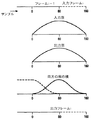
図2は、使用されるウインドウイング及びフレーミングを示している。音声強化デバイスの出力は、一つのフレームの全ディレイ、すなわち当該例において10ミリ秒で、処理された場合(version)の入力信号である。
【0014】
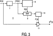
図3は、強度(magnitude)ブロック7、バックグラウンドレベル更新ブロック8、信号対雑音比ブロック9、フィルタ更新ブロック10、及び処理手段11を有する、周波数領域における適応型フィルタリングのブロック図を示している。後続する演算は、スペクトラムS[k]の各周波数コンポーネントkについてなされる。まず、強度ブロック7において、絶対値|S[k]|は、関係式
|S[k]|=[(R{S[k]})2+(I{S[k]})2]1/2
を使用して計算される。ここで、R{S[k]}及びI{S[k]}はそれぞれ、当該例において0≦k<129の場合のスペクトラムの実数部及び虚数部である。それから、バックグラウンドレベル更新ブロックは、カレントフレームに対して、予期されたバックグラウンド強度B[k]を計算するために、入力強度|S[k]|を使用する。
【0015】
信号対雑音比(SNR)は、関係式
SNR[k]=|S[k]|/B[k]
を使用して計算され、フィルタ更新ブロック10によってフィルタ強度F[k]を計算するために使用される。
【0016】
最後に、式
Rb{Sb[k]}=R{S[k]}・F[k]と、
Ib{Sb[k]}=I{S[k]}・F[k]と
を使用してフィルタリングがなされる。
【0017】
バックグラウンド雑音への全体的な位相の寄与(overall phase contribution of background noise)は、前記スペクトラムの実数部及び虚数部に渡って一様に分散しているので、周波数領域における振幅の局所的な低減は、加算された位相情報も低減させることが想定される。しかしながら、振幅スペクトラムのみを変化させ、バックグラウンド信号への位相の寄与を変化させなくても十分であるかどうかは議論の余地がある。前記バックグラウンド雑音が周期的な信号のみから構成されている場合には、当該信号の振幅及び位相コンポーネントを測定し、同じ周期と振幅とを備え、180度回転した位相を備える合成信号を加算することは容易であろう。解析期間中の雑音信号への位相の寄与は一定ではなく、さらに、信号対雑音比のみが測定されるので、各周波数領域に対して個別のファクタで入力信号のエネルギーを抑制することしかできない。これは、通常、バックグラウンドエネルギーだけでなく、音声信号のエネルギーも抑制し得る。しかしながら、知覚のために重要となる音声信号の成分は、通常、他の領域よりも高い信号対雑音比を有しているので、実際上は、本方法は十分満足できる方法である。
【0018】
図4は、バックグラウンドレベル更新ブロック8を、より詳細に示している。ブロック8は、処理手段12乃至16と、コンパレータ18及び19を具備するコンパレータ手段17と、メモリユニット20とを有している。
【0019】
前記バックグラウンドレベルは、後続するステップで更新される。
−まず、メモリユニット20及び処理手段14を介して、バックグラウンドレベルの先行する値B−1[k]が、B’[k]をもたらすファクタU[k]によって増幅される。
−それから、前記出力は、処理手段12、13、15、及び16を介して得られる現時点の絶対値入力レベル|S[k]|と、増幅されたバックグラウンドレベルB’[k]とのスケーリングされた合成である値B”[k]と比較される。コンパレータ18によって、より小さな方が、バックグラウンドレベルB’’’[k]に対する候補として選択される。
−最後に、コンパレータ19によって、バックグラウンドレベルB’’’[k]は、最小限許容されるバックグラウンドレベルBminによって制限され、新たなバックグラウンドレベルをもたらす。これは、バックグラウンドレベル更新ブロック8の出力ともなる。
【0020】
従って、計算されたバックグラウンドの強度は、U[k]及びD[k]が周波数に依存するスケーリングファクタであり、Cが定数である場合、
B’[k]=B−1[k]・U[k]と、
B”[k]=(B’[k]・D[k])+(|S[k]|・C・(1−D[k]))
とを用いる一方、最小限許容されるバックグラウンドレベルBminを用いて、関係式
B[k]=max{min{B’[k],B”[k]},Bmin}
で表され得る。
【0021】
本実施例において、入力スケールファクタCは4にセットされる。Bminは64にセットされる。スケーリング関数U[k]及びD[k]は、各フレームに対して一定であり、周波数インデックスkのみに依存している。当該関数は
U[k]=a+k/b、及びD[k]=c−k/d
として規定される。ここで、aは1.002、bは16384、cは0.97、及びdは1024にセットされてもよい。
【0022】
図5は、フィルタ更新ブロック10をより詳細に示している。ブロック10は、処理手段21乃至27と、コンパレータ29及び30を具備するコンパレータ手段28と、メモリユニット31とを有している。
【0023】
ブロック10は、2段、すなわち、内部フィルタ値F’[k]の適応のための1段と、出力フィルタ値のスケーリング及びクリッピング(clipping)のための他の1段とを有している。内部フィルタ値F’[k]の適応は、関係式 F”[k]=F’−1[k]・Eと、
δ[k]=(1−F”[k])・SNR[k]と、
F’[k]=F”[k](δ[k]≦1の場合)、又はF’[k]=F”[k]+G・δ[k](δ[k]≦1以外の場合)と
によれば、入力及びフィルタリングレベルが依存するステップ値によって、先行するフレームの、スケールダウンされた内部フィルタ値を増加させることによってなされる。ここで、Eは0.9375にセットされてもよく、Gは0.0416にセットされてもよい。
【0024】
前記出力フィルタ値のスケーリング及びクリッピングは、
F[k]=max{min{H・F’[k],1},Fmin}
を用いてなされる。ここで、Hは1.5にセットされてもよく、Fminは0.2にセットされてもよい。
【0025】
前記出力フィルタリングをさらにスケーリング及びクリッピングする理由は、前記バックグラウンド雑音よりもずっと高いエネルギーを有するスペクトル領域に対する帯域通過特性を備えるフィルタを得ることにある。
【0026】
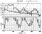
図6は、バックグラウンド雑音が混入している有音声セグメントのフレームに対するフィルタ更新ブロック及び前記バックグラウンドレベルの出力を示している。
【0027】
上記のような独立のバックグラウンド雑音減算器(BNS)を具備する音声
強化デバイスは、音声符号化システム、特にP2CM符号化システムのエンコーダにおいて適用されてもよい。前記P2CM符号化システムのエンコーダは、プリプロセッサ及びADPCMエンコーダを有している。前記プリプロセッサは、特に、例えば、R.リフェブレ及びC.ラフラメによるICASSP 第1巻、335乃至338頁(1997年)(R.Lefebre,C.Laflamme,ICASSP,vol.1,p.335−338,1997)に記載の“オーディオ符号化における雑音スペクトラム整形のためのスペクトル振幅ワーピング(Spectral Amplitude Warping(SAW) for Noise Spectrum Shaping in Audio Coding)”に記載されているような振幅ワーピングを適用することによって、符号化に先行してオーディオ入力信号の信号スペクトラムを整形(modify)する。当該振幅ワーピングは、周波数領域においてなされるので、前記バックグラウンド雑音の低減が、前記プリプロセッサにおいて実現される。時間−周波数変換後、バックグラウンド雑音の低減及び振幅ワーピングは連続的に達成され、その後、周波数−時間変換がなされる。この場合、前記音声強化デバイスの入力信号は、前記プリプロセッサの入力信号によって形成される。前記プリプロセッサにおいて、当該入力信号は、もたらされる信号における雑音低減が達成される態様で変化するので、ワーピングは、雑音が低減された信号についてなされる。前記入力信号に応答して得られる、前記プリプロセッサの出力は、遅延型の場合の前記入力フレームを形成し、ADPCMエンコーダに供給される。当該遅延(当該例においては10ミリ秒)は、BNSの内部処理にほぼ起因している。ADPCMエンコーダに対する他の入力信号は、ADPCMエンコーダのビットストリーム出力における符号語のためのビット割り当てを決定するコーデックモード信号(codec mode signal)によって形成される。ADPCMエンコーダは、前段処理された信号フレーム(pre−processed signal frame)における各サンプルに対して符号語を生成する。符号語は、それから、当該例においては、80個の符号のフレームにおさめられる。選択されたコーデックモードに依存して、もたらされたビットストリームは、例えば11.2、12.8、16、21.6、24、又は32kbit/sのビットレートを有する。
【0028】
上記の実施例は、P2CMオーディオエンコーダにおける信号処理手段において実行可能なコンピュータプログラムの形態であってもよいアルゴリズムによって実現される。図の一部が、あるプログラミング可能な機能を実行するためのユニットを示している場合、当該ユニットは前記コンピュータプログラムのサブパーツとみなされなければならない。
【0029】
記載されている本発明は、記載されている実施例に限定されるものではない。それらに関する変形例は可能である。特に、a、b、c、d、E、G及びHの値が単なる例として与えられており、他の値が可能であることは注意されてもよい。
【図面の簡単な説明】
【図1】 本発明による、単独のバックグラウンド雑音減算器(BNS)を具備する音声強化デバイスの基本的なブロック図を示している。
【図2】 BNSにおけるフレーミング及びウィンドウイングを示している。
【図3】 BNSにおける周波数領域適用型フィルタのブロック図を示している。
【図4】 BNSにおけるバックグラウンドレベルの更新のブロック図を示している。
【図5】 BNSにおけるフィルタの更新のブロック図を示している。
【図6】 測定されたバックグラウンドレベル及びもたらされた周波数領域フィルタリングを伴うバックグラウンド雑音が混入しているボイス音声セグメントを示している。[0001]
BACKGROUND OF THE INVENTION
The present invention relates to a time-frequency conversion unit that converts a frame of time domain samples of an audio signal into a frequency domain, background noise reduction means for reducing noise in the frequency domain, and frequency of the audio signal with reduced noise. The present invention relates to a speech enhancement device for reducing background noise, comprising a frequency-to-time conversion unit for converting from the domain to the time domain.
[0002]
The speech enhancement device can be used in speech coding systems, for example, for storage in digital telephone answering equipment and voicemail applications, in voice response systems in “in-car” navigation systems, and in communication applications such as Internet telephones. And may be applied to
[0003]
[Prior art]
In order to improve the sound quality of a noisy voice recording, the noise level must be known. Only a noisy voice can be used for recording a single microphone. The noise level must be estimated from the signal alone. The method of measuring the noise uses a region without speech activity, and the spectrum of the sample frame while there is speech activity is the spectrum of the sample frame obtained while there is no speech activity. Compare and update the spectrum. Reference is made, for example, to US Pat. No. 6,070,137. The problem with this method is that a voice action detector must be used. It is difficult to produce a robust sound detector that works well even when the signal to noise ratio is relatively high. Another problem is that the non-speech zone may be very narrow or rather not. When the noise is in an unsteady state, the approach becomes even more difficult because the noise characteristics can change during speech activity.
[0004]
It is further known to use a statistical model that measures the change of each spectral component in the signal without using voice or non-voice two-way selection (IEEE, communications field for ASSP, Vol. 32, No. 6 (December 1984) (IEEE Trans. On ASSP, vol. 32, No. 6, Dec. 1984) by Ephraim, Malah, “MMSE short-term spectral amplitude estimation. Sound enhancement using a device (see “Speech Enhancement Using MMSE Short-Time Spectral Amplitude Estimator”). The problem with the method is that when the background noise is in a non-steady state, the estimate must be based on the frame at the nearest neighbor. In the speech length, some speech spectrum bands may always be on the actual noise level. This results in an incorrect estimate of the noise level for that spectrum band.
[0005]
[Problems to be solved by the invention]
It is an object of the present invention to predict the level of background noise in a single microphone voice recording without the use of a voice action detector and with a significantly reduced noise level estimation.
[0006]
[Means for Solving the Problems]
Thus, according to the present invention, as described in the opening paragraph, the audio enhancement device has the background noise reduction means for the time component for each frequency component in the current frame of the audio signal. -The predicted background intensity in response to the measured input intensity S [k] from the frequency conversion unit and in response to the previously calculated background intensity B -1 [k]. A background level update block for calculating B [k] and, for each of the frequency components, responds to the predicted background intensity B [k] and the measured input intensity S [k In response to a signal to noise ratio block for calculating a signal to noise ratio SNR [k]; A filter update block for calculating the filter strength F [k] for the measured input strength S [k] in response to the signal-to-noise ratio SNR [k] for each of the frequency components; It is characterized by having.
[0007]
The invention further relates to a speech coding system and to a speech encoder for such a speech coding system comprising a speech enhancement device according to the invention, in particular a P 2 CM audio coding system. In particular, an adaptive differential pulse code modulation (ADPCM) coder and a preprocessor unit comprising the speech enhancement system are provided in the encoder of the P 2 CM audio coding system.
[0008]
These and other aspects of the invention are apparent from and will be elucidated with reference to the embodiments described hereinafter.
[0009]
An object of the present invention is to provide a method for solving the above problems.
[0010]
DETAILED DESCRIPTION OF THE INVENTION
As an example, in an audio enhancement device, the audio input signal is divided into, for example, 10 millisecond frames. For example, in the case of a sampling frequency of 8 kHz, the frame is composed of 80 samples. Each sample is represented by 16 bits, for example.
[0011]
The BNS is basically a frequency domain adaptive filter. Prior to actual filtering, the speech enhancement device input frames must be transformed into the frequency domain. After filtering, the frequency domain information is transformed back to the time domain. Since the characteristics of the BNS filter change over time, special care must be taken to prevent discontinuities at frame boundaries.
[0012]
FIG. 1 shows a block diagram of a voice enhancement device comprising a BNS. The sound enhancement device includes an input
S * b w, i [n] = S b w, i [n] + S b w, i−1 [n + 80] (0 ≦ n <80)
Represented by
[0013]
FIG. 2 shows the windowing and framing used. The output of the audio enhancement device is the input signal when processed in a total delay of one frame, i.e. 10 ms in this example.
[0014]
FIG. 3 shows a block diagram of adaptive filtering in the frequency domain comprising a
Calculated using Here, R {S [k]} and I {S [k]} are the real part and the imaginary part of the spectrum when 0 ≦ k <129 in the example, respectively. The background level update block then uses the input intensity | S [k] | to calculate the expected background intensity B [k] for the current frame.
[0015]
The signal-to-noise ratio (SNR) is expressed by the relation SNR [k] = | S [k] | / B [k].
And is used by the
[0016]
Finally, the formula R b {S b [k]} = R {S [k]} · F [k],
Filtering is performed using I b {S b [k]} = I {S [k]} · F [k].
[0017]
Overall phase contribution of the background noise (overall phase contribution of background noise), so are uniformly distributed over the real and imaginary parts of the spectrum, local reduction of the amplitude in the frequency domain It is assumed that the added phase information is also reduced. However, by changing only the amplitude spectrum, whether sufficient phase contribution such a varied without having to background signal is controversial. When the background noise is composed of only the periodic signal is to measure the amplitude and phase components of the signal, e Bei the same period and amplitude, adding the synthesized signal having the phase rotated by 180 degrees It will be easy to do. Phase contribution to the noise signal in the analysis period is not constant, further, since only the signal-to-noise ratio is measured, it is only possible to suppress the energy of the input signals in separate factor for each frequency domain. This is usually not only background energy can also be suppressed energy of the speech signal. However, components of the audio signal, which is important for perception, usually because it has a high signal-to-noise ratio than other regions, in practice, the method is sufficiently satisfactory method.
[0018]
FIG. 4 shows the background
[0019]
The background level is updated in subsequent steps.
First, via the
The output is then scaled between the current absolute value input level | S [k] | obtained through the processing means 12, 13, 15 and 16 and the amplified background level B ′ [k]. Is compared with the value B ″ [k], which is the synthesized value. The
-Finally, by the
[0020]
Thus, the calculated background intensity is a scaling factor where U [k] and D [k] are frequency dependent, and C is a constant:
B ′ [k] = B −1 [k] · U [k]
B ″ [k] = (B ′ [k] · D [k]) + (| S [k] | · C · (1−D [k]))
On the other hand, using the minimum allowable background level B min , the relational expression B [k] = max {min {B ′ [k], B ″ [k]}, B min }
It can be expressed as
[0021]
In this embodiment, the input scale factor C is set to 4. B min is set to 64. The scaling functions U [k] and D [k] are constant for each frame and depend only on the frequency index k. The function is U [k] = a + k / b and D [k] = c−k / d
Is defined as Here, a may be set to 1.002, b may be set to 16384, c may be set to 0.97, and d may be set to 1024.
[0022]
FIG. 5 shows the
[0023]
δ [k] = (1−F ″ [k]) · SNR [k],
F ′ [k] = F ″ [k] (when δ [k] ≦ 1) or F ′ [k] = F ″ [k] + G · δ [k] (when other than δ [k] ≦ 1) ) By increasing the scaled down internal filter value of the preceding frame by a step value on which the input and filtering level depend. Here, E may be set to 0.9375 and G may be set to 0.0416.
[0024]
The scaling and clipping of the output filter value is
F [k] = max {min {H · F ′ [k], 1}, F min }
Is made using. Here, H may be set to 1.5, and F min may be set to 0.2.
[0025]
The reason for further scaling and clipping the output filtering is to obtain a filter having a bandpass characteristic for spectral regions with the much higher energy than the background noise.
[0026]
FIG. 6 shows the filter update block and the background level output for frames of voiced segments with background noise.
[0027]
A speech enhancement device comprising an independent background noise subtractor (BNS) as described above may be applied in speech coding systems, particularly in encoders of P 2 CM coding systems. The encoder of the P 2 CM encoding system has a preprocessor and an ADPCM encoder. The preprocessor is, for example, R.I. Refebre and C.I. ICASSP by Raframe, Vol. 1, pages 335 to 338 (1997) (R. Lefebre, C. Laflamme, IASSSP, vol. 1, p. 335-338, 1997) By applying amplitude warping as described in “Spectral Amplitude Warping (SAW) for Noise Spectrum Shaping in Audio Coding”, the signal spectrum of the audio input signal is shaped prior to encoding. (Modify). Since the amplitude warping is performed in the frequency domain, the background noise is reduced in the preprocessor. After time-frequency conversion, background noise reduction and amplitude warping are continuously achieved, after which frequency-time conversion is performed. In this case, the input signal of the audio enhancement device is formed by the input signal of the preprocessor. In the preprocessor, the input signal changes in such a way that noise reduction in the resulting signal is achieved, so warping is done on the noise reduced signal. The output of the preprocessor obtained in response to the input signal forms the input frame in the case of a delay type and is supplied to an ADPCM encoder. The delay (10 milliseconds in this example) is almost due to the internal processing of the BNS. Another input signal to the ADPCM encoder is formed by a codec mode signal that determines the bit allocation for the codeword in the bitstream output of the ADPCM encoder. The ADPCM encoder generates a codeword for each sample in the pre-processed signal frame. The codeword is then placed in a frame of 80 codes in this example. Depending on the selected codec mode, the resulting bitstream has a bit rate of, for example, 11.2, 12.8, 16, 21.6, 24, or 32 kbit / s.
[0028]
The above embodiment is realized by an algorithm which may be in the form of a computer program executable in the signal processing means in the P 2 CM audio encoder. If part of the figure shows a unit for performing certain programmable functions, the unit must be considered a sub-part of the computer program.
[0029]
The described invention is not limited to the described embodiments. Variations on them are possible. In particular, it may be noted that the values for a, b, c, d, E, G and H are given as examples only, and other values are possible.
[Brief description of the drawings]
FIG. 1 shows a basic block diagram of a speech enhancement device comprising a single background noise subtractor (BNS) according to the present invention.
FIG. 2 shows framing and windowing in BNS.
FIG. 3 shows a block diagram of a frequency domain applied filter in BNS.
FIG. 4 shows a block diagram of background level updates in the BNS.
FIG. 5 shows a block diagram of filter update in BNS.
FIG. 6 shows a voice speech segment contaminated with background noise with measured background level and resulting frequency domain filtering.
Claims (9)
前記バックグラウンドレベル更新ブロックが、前記先行して計算されたバックグラウンド強度B −1 [k]を得るためのメモリユニットと、U[k]及びD[k]が周波数に依存するスケーリングファクタであると共にCが定数である場合、
B’[k]=B −1 [k]・U[k]と、
B”[k]=(B’[k]・D[k])+(|S[k]|・C・(1−D[k]))とを用いる一方、最小限許容されるバックグラウンドレベルB min を用いて、関係式
B[k]=max{min{B’[k],B”[k]},B min }
による前記先行して予測されたバックグラウンド強度を更新するための処理手段及びコンパレータ手段とを有することを特徴とする音声強化デバイス。A time-frequency conversion unit for converting a frame of time domain samples of an audio signal into a frequency domain, background noise reduction means for performing noise reduction in the frequency domain, and the audio signal with reduced noise A speech enhancement device for reducing background noise comprising a frequency-to-time conversion unit for transforming from the frequency domain to the time domain, wherein the background noise reduction means comprises: with respect to the frequency component, the time - from the frequency conversion unit, with responding to the measured input intensity S [k], in accordance with the preceding background intensity was calculated B -1 [k], the predicted A background for calculating the background intensity B [k]. And ground level update block, for each of said frequency components, said with responding to the predicted background intensity B [k], in response to the measured input intensity S [k], the signal-to-noise ratio SNR [ k] for a signal to noise ratio block and for each said frequency component, the filter strength F for said measured input strength S [k] according to said signal to noise ratio SNR [k] a sound reinforcement device to have a filter update block to calculate the [k],
The background level update block is a memory unit for obtaining the previously calculated background intensity B −1 [k], and U [k] and D [k] are frequency dependent scaling factors. And C is a constant,
B ′ [k] = B −1 [k] · U [k],
B ″ [k] = (B ′ [k] · D [k]) + (| S [k] | · C · (1−D [k])) Using level B min , relational expression
B [k] = max {min {B ′ [k], B ″ [k]}, B min }
A speech enhancement device comprising processing means and comparator means for updating the previously predicted background intensity according to .
SNR[k]=|S[k]|/B[k]
による前記測定された入力強度S[k]に応じて、信号対雑音比SNR[k]を計算するための手段を有することを特徴とする請求項1に記載の音声強化デバイス。The signal-to-noise ratio block, the predicted when responding to the background intensity B [k] Both relationship SNR [k] = | S [ k] | / B [k]
The speech enhancement device of claim 1 , comprising means for calculating a signal-to-noise ratio SNR [k] in response to the measured input intensity S [k] according to .
F[k]=max{min{H・F’[k],1},Fmin}
による前記フィルタ強度をスケーリングすると共にクリッピングするためのコンパレータ手段を有することを特徴とする請求項5に記載の音声強化デバイス。In the second means, when H is a constant, F min is the minimum filter value, and F ′ [k] is the internal filter value, the relational expression F [k] = max {min {H · F ′ [k], 1}, F min }
6. A sound enhancement device according to claim 5 , comprising comparator means for scaling and clipping the filter strength according to.
Applications Claiming Priority (2)
| Application Number | Priority Date | Filing Date | Title |
|---|---|---|---|
| EP01201304 | 2001-04-09 | ||
| PCT/IB2002/001050 WO2002082427A1 (en) | 2001-04-09 | 2002-03-25 | Speech enhancement device |
Publications (3)
| Publication Number | Publication Date |
|---|---|
| JP2004519737A JP2004519737A (en) | 2004-07-02 |
| JP2004519737A5 JP2004519737A5 (en) | 2008-04-10 |
| JP4127792B2 true JP4127792B2 (en) | 2008-07-30 |
Family
ID=8180126
Family Applications (1)
| Application Number | Title | Priority Date | Filing Date |
|---|---|---|---|
| JP2002580312A Expired - Fee Related JP4127792B2 (en) | 2001-04-09 | 2002-03-25 | Audio enhancement device |
Country Status (8)
| Country | Link |
|---|---|
| US (1) | US6996524B2 (en) |
| EP (1) | EP1386313B1 (en) |
| JP (1) | JP4127792B2 (en) |
| KR (1) | KR20030009516A (en) |
| CN (1) | CN1240051C (en) |
| AT (1) | ATE331279T1 (en) |
| DE (1) | DE60212617T2 (en) |
| WO (1) | WO2002082427A1 (en) |
Families Citing this family (19)
| Publication number | Priority date | Publication date | Assignee | Title |
|---|---|---|---|---|
| DE60215547T2 (en) * | 2002-01-25 | 2007-08-02 | Koninklijke Philips Electronics N.V. | METHOD AND UNIT FOR SUBTRACING THE QUANTIZATION RATES OF A PCM SIGNAL |
| JP2006084754A (en) * | 2004-09-16 | 2006-03-30 | Oki Electric Ind Co Ltd | Voice recording and reproducing apparatus |
| US9318119B2 (en) * | 2005-09-02 | 2016-04-19 | Nec Corporation | Noise suppression using integrated frequency-domain signals |
| US8949120B1 (en) | 2006-05-25 | 2015-02-03 | Audience, Inc. | Adaptive noise cancelation |
| US8731913B2 (en) * | 2006-08-03 | 2014-05-20 | Broadcom Corporation | Scaled window overlap add for mixed signals |
| JP4827661B2 (en) * | 2006-08-30 | 2011-11-30 | 富士通株式会社 | Signal processing method and apparatus |
| WO2009082299A1 (en) * | 2007-12-20 | 2009-07-02 | Telefonaktiebolaget L M Ericsson (Publ) | Noise suppression method and apparatus |
| US8515097B2 (en) * | 2008-07-25 | 2013-08-20 | Broadcom Corporation | Single microphone wind noise suppression |
| US9253568B2 (en) * | 2008-07-25 | 2016-02-02 | Broadcom Corporation | Single-microphone wind noise suppression |
| GB2466668A (en) * | 2009-01-06 | 2010-07-07 | Skype Ltd | Speech filtering |
| US20110178800A1 (en) * | 2010-01-19 | 2011-07-21 | Lloyd Watts | Distortion Measurement for Noise Suppression System |
| US9558755B1 (en) | 2010-05-20 | 2017-01-31 | Knowles Electronics, Llc | Noise suppression assisted automatic speech recognition |
| US9640194B1 (en) | 2012-10-04 | 2017-05-02 | Knowles Electronics, Llc | Noise suppression for speech processing based on machine-learning mask estimation |
| US9536540B2 (en) | 2013-07-19 | 2017-01-03 | Knowles Electronics, Llc | Speech signal separation and synthesis based on auditory scene analysis and speech modeling |
| DE112015003945T5 (en) | 2014-08-28 | 2017-05-11 | Knowles Electronics, Llc | Multi-source noise reduction |
| CN104464745A (en) * | 2014-12-17 | 2015-03-25 | 中航华东光电(上海)有限公司 | Two-channel speech enhancement system and method |
| CN104900237B (en) * | 2015-04-24 | 2019-07-05 | 上海聚力传媒技术有限公司 | A kind of methods, devices and systems for audio-frequency information progress noise reduction process |
| WO2019009204A1 (en) * | 2017-07-03 | 2019-01-10 | パイオニア株式会社 | Signal processing device, control method, program and storage medium |
| US11409512B2 (en) * | 2019-12-12 | 2022-08-09 | Citrix Systems, Inc. | Systems and methods for machine learning based equipment maintenance scheduling |
Family Cites Families (4)
| Publication number | Priority date | Publication date | Assignee | Title |
|---|---|---|---|---|
| JP3484757B2 (en) * | 1994-05-13 | 2004-01-06 | ソニー株式会社 | Noise reduction method and noise section detection method for voice signal |
| US5706395A (en) * | 1995-04-19 | 1998-01-06 | Texas Instruments Incorporated | Adaptive weiner filtering using a dynamic suppression factor |
| US6175602B1 (en) * | 1998-05-27 | 2001-01-16 | Telefonaktiebolaget Lm Ericsson (Publ) | Signal noise reduction by spectral subtraction using linear convolution and casual filtering |
| US6604071B1 (en) * | 1999-02-09 | 2003-08-05 | At&T Corp. | Speech enhancement with gain limitations based on speech activity |
-
2002
- 2002-03-25 JP JP2002580312A patent/JP4127792B2/en not_active Expired - Fee Related
- 2002-03-25 AT AT02713141T patent/ATE331279T1/en not_active IP Right Cessation
- 2002-03-25 DE DE60212617T patent/DE60212617T2/en not_active Expired - Lifetime
- 2002-03-25 KR KR1020027016632A patent/KR20030009516A/en active IP Right Grant
- 2002-03-25 WO PCT/IB2002/001050 patent/WO2002082427A1/en active IP Right Grant
- 2002-03-25 CN CNB028011023A patent/CN1240051C/en not_active Expired - Fee Related
- 2002-03-25 EP EP02713141A patent/EP1386313B1/en not_active Expired - Lifetime
- 2002-04-04 US US10/116,596 patent/US6996524B2/en not_active Expired - Lifetime
Also Published As
| Publication number | Publication date |
|---|---|
| KR20030009516A (en) | 2003-01-29 |
| EP1386313B1 (en) | 2006-06-21 |
| WO2002082427A1 (en) | 2002-10-17 |
| DE60212617T2 (en) | 2007-06-14 |
| ATE331279T1 (en) | 2006-07-15 |
| JP2004519737A (en) | 2004-07-02 |
| EP1386313A1 (en) | 2004-02-04 |
| US6996524B2 (en) | 2006-02-07 |
| US20020156624A1 (en) | 2002-10-24 |
| CN1460248A (en) | 2003-12-03 |
| CN1240051C (en) | 2006-02-01 |
| DE60212617D1 (en) | 2006-08-03 |
Similar Documents
| Publication | Publication Date | Title |
|---|---|---|
| JP4127792B2 (en) | Audio enhancement device | |
| RU2329550C2 (en) | Method and device for enhancement of voice signal in presence of background noise | |
| AU696152B2 (en) | Spectral subtraction noise suppression method | |
| KR101120679B1 (en) | Gain-constrained noise suppression | |
| US6122610A (en) | Noise suppression for low bitrate speech coder | |
| JP3842821B2 (en) | Method and apparatus for suppressing noise in a communication system | |
| JP4512574B2 (en) | Method, recording medium, and apparatus for voice enhancement by gain limitation based on voice activity | |
| US20080312914A1 (en) | Systems, methods, and apparatus for signal encoding using pitch-regularizing and non-pitch-regularizing coding | |
| JP5153886B2 (en) | Noise suppression device and speech decoding device | |
| JP2001513916A (en) | High resolution post-processing method for speech decoder | |
| US20100169082A1 (en) | Enhancing Receiver Intelligibility in Voice Communication Devices | |
| Kornagel | Techniques for artificial bandwidth extension of telephone speech | |
| CN109102823A (en) | A kind of sound enhancement method based on subband spectrum entropy | |
| JP4006770B2 (en) | Noise estimation device, noise reduction device, noise estimation method, and noise reduction method | |
| JP2002123298A (en) | Method and device for encoding signal, recording medium recorded with signal encoding program | |
| JP2003058186A (en) | Method and device for suppressing noise | |
| CA2401672A1 (en) | Perceptual spectral weighting of frequency bands for adaptive noise cancellation | |
| KR20180010115A (en) | Speech Enhancement Device | |
| KR100931487B1 (en) | Noisy voice signal processing device and voice-based application device including the device | |
| JP4691079B2 (en) | Audio signal section estimation apparatus, method, program, and recording medium recording the same | |
| Nemer | Acoustic Noise Reduction for Mobile Telephony | |
| JP2002175100A (en) | Adaptive noise suppression/voice-encoding device | |
| KR100931181B1 (en) | Method of processing noise signal and computer readable recording medium therefor | |
| Balaji et al. | A Novel DWT Based Speech Enhancement System through Advanced Filtering Approach with Improved Pitch Synchronous Analysis | |
| Balaji et al. | An Advanced Speech Enhancement Approach with Improved Pitch Synchronous Analysis |
Legal Events
| Date | Code | Title | Description |
|---|---|---|---|
| RD04 | Notification of resignation of power of attorney |
Free format text: JAPANESE INTERMEDIATE CODE: A7424 Effective date: 20041118 |
|
| A621 | Written request for application examination |
Free format text: JAPANESE INTERMEDIATE CODE: A621 Effective date: 20050324 |
|
| RD03 | Notification of appointment of power of attorney |
Free format text: JAPANESE INTERMEDIATE CODE: A7423 Effective date: 20070323 |
|
| A131 | Notification of reasons for refusal |
Free format text: JAPANESE INTERMEDIATE CODE: A131 Effective date: 20071120 |
|
| A524 | Written submission of copy of amendment under article 19 pct |
Free format text: JAPANESE INTERMEDIATE CODE: A524 Effective date: 20080219 |
|
| TRDD | Decision of grant or rejection written | ||
| A01 | Written decision to grant a patent or to grant a registration (utility model) |
Free format text: JAPANESE INTERMEDIATE CODE: A01 Effective date: 20080415 |
|
| A01 | Written decision to grant a patent or to grant a registration (utility model) |
Free format text: JAPANESE INTERMEDIATE CODE: A01 |
|
| A711 | Notification of change in applicant |
Free format text: JAPANESE INTERMEDIATE CODE: A711 Effective date: 20080424 |
|
| A61 | First payment of annual fees (during grant procedure) |
Free format text: JAPANESE INTERMEDIATE CODE: A61 Effective date: 20080512 |
|
| FPAY | Renewal fee payment (event date is renewal date of database) |
Free format text: PAYMENT UNTIL: 20110523 Year of fee payment: 3 |
|
| R150 | Certificate of patent or registration of utility model |
Free format text: JAPANESE INTERMEDIATE CODE: R150 |
|
| FPAY | Renewal fee payment (event date is renewal date of database) |
Free format text: PAYMENT UNTIL: 20110523 Year of fee payment: 3 |
|
| FPAY | Renewal fee payment (event date is renewal date of database) |
Free format text: PAYMENT UNTIL: 20120523 Year of fee payment: 4 |
|
| FPAY | Renewal fee payment (event date is renewal date of database) |
Free format text: PAYMENT UNTIL: 20130523 Year of fee payment: 5 |
|
| FPAY | Renewal fee payment (event date is renewal date of database) |
Free format text: PAYMENT UNTIL: 20130523 Year of fee payment: 5 |
|
| R250 | Receipt of annual fees |
Free format text: JAPANESE INTERMEDIATE CODE: R250 |
|
| R250 | Receipt of annual fees |
Free format text: JAPANESE INTERMEDIATE CODE: R250 |
|
| LAPS | Cancellation because of no payment of annual fees |