JP4124987B2 - Image forming apparatus - Google Patents
Image forming apparatus Download PDFInfo
- Publication number
- JP4124987B2 JP4124987B2 JP2001293012A JP2001293012A JP4124987B2 JP 4124987 B2 JP4124987 B2 JP 4124987B2 JP 2001293012 A JP2001293012 A JP 2001293012A JP 2001293012 A JP2001293012 A JP 2001293012A JP 4124987 B2 JP4124987 B2 JP 4124987B2
- Authority
- JP
- Japan
- Prior art keywords
- recording material
- image
- toner image
- supply
- image forming
- Prior art date
- Legal status (The legal status is an assumption and is not a legal conclusion. Google has not performed a legal analysis and makes no representation as to the accuracy of the status listed.)
- Expired - Fee Related
Links
Images


Description
【0001】
【発明の属する技術分野】
本発明は、電子写真方式を用い、記録材の片面に画像形成を行った後に同じ記録材の裏面にも画像形成を行う両面画像形成が可能な画像形成装置に関する。
【0002】
【従来の技術】
従来、電子写真方式を用いた複数の画像形成部を備え、各画像形成部でそれぞれ色の異なったトナー像を形成し、そのトナー像を同一記録材上に順次重ね合わせて転写して、記録材にカラー画像を形成する画像形成装置が種々提案されている。また無端ベルト状の記録材搬送部材である転写ベルトを備え、この転写ベルトに沿って複数の画像形成部を直線的に配置した、カラー高速記録を行うためのカラー複写機が提案されている。
【0003】
このカラー複写機の一例を図1に基づいて簡単に説明すると、装置内には、第1、第2、第3、第4の画像形成部Pa、Pb、Pc、Pdが配置され、画像形成部は、それぞれ専用の像担持体である電子写真感光ドラム3a、3b、3c、3dを具備し、各感光ドラム上に各色のトナー像が形成される。各感光ドラムに隣接して転写ベルト(ベルト状記録材搬送部材)30が設置され、各感光ドラム3上に形成された各色のトナー像が、転写ベルト30上に担持して搬送される記録材P上に重ね合わせて転写される。各色のトナー像が転写された記録材Pは、定着器9で加熱及び加圧によりトナー像が定着された後、カラーの記録画像として装置外に排出される。
【0004】
このような画像形成装置では、記録材上のトナーが定着手段としての定着器9の定着ローラ51に付着するのを防ぐために、オイル溜53にジメチルシリコーンオイル等の離型剤オイルを溜めて、その離型剤オイルを塗布ローラ50で定着ローラ51の表面に塗布することを行っている。
【0005】
また転写が終了した転写ベルト30上には、トナー汚れ(主として感光ドラムから転写ベルト上に転移した転写残りトナー(かぶりトナーと呼ばれる)からなり、一部紙粉等も含む)が存在するので、清掃手段としての転写ベルトクリーナ8に設けたゴムなどの弾性材料製のクリーニングブレード8aを転写ベルトに当接して、トナー汚れを掻き落とし、転写ベルトクリーナ8内に回収している。
【0006】
図1に示した構成においては、クリーニングブレードのエッジ面(転写ベルトへのブレード当接部からブレード厚み方向に平行な面)が、重力方向に対して上を向くようにクリーニングブレード8aが配置されている。
【0007】
このようなクリーニングブレードの配置は、ブレードエッジ面にトナーを保持し易く、このトナー保持により、転写ベルトとの当接部において安定した摺動性を得たり、トナーの研磨効果も加わることでのクリーニング性能の向上を得ることができる。
【0008】
【発明が解決しようとする課題】
しかしながら、このような画像形成装置において、記録材の両面に画像形成を行った場合、クリーニングブレード8aのエッジ上にトナーが過剰に積みあがり、積もったトナーがクリーナ8から上方に溢れてしまう問題が発生した。溢れたトナーは記録材の裏面に付着して裏汚れとなったり、装置内に飛散して装置内を汚す。
【0009】
本発明者らが検討したところ、クリーニングブレード8aのエッジ上にトナーが積み上がるのは、つぎのような理由によることが分かった。すなわち、記録材の片面に画像形成が行われ、定着器9により定着された後、裏面(2面目)の画像形成を行うべく記録材を裏返して再び転写ベルト30上に担持したとき、定着時に記録材の表面(1面目)に付着した定着オイルが転写ベルト30上に付着して、クリーニングブレード8aに運ばれる。このため、転写ベルト30上の汚れトナーがクリーニングブレード8aに運ばれたときに、そこで粉体のトナーにオイルが混ざって粘土状になり、クリーニングブレード8aのエッジ面上に積み上がる。
【0010】
以上のような問題は、感光ドラム上のトナー像を一旦中間転写体に転写し、ついで中間転写体から記録材に転写する中間転写方式の画像形成装置においても、中間転写体に対して上記構成のクリーニング装置を用いた場合に、同様に生じる。
【0011】
本発明の目的は、記録材担持体や中間転写体や転写部材に対するクリーニング部材へのトナーの過剰な積み上がりによるトナー溢れを防止し、機内汚染や記録材の裏汚れ等の問題をなくした画像形成装置を提供することである。
【0012】
【課題を解決するための手段】
上記目的は本発明に係る画像形成装置にて達成される。要約すれば、本発明は、トナー像を形成する像形成手段と、記録材を担持搬送する記録材搬送部材と、該記録材搬送部材の表面に当接するクリーニングブレードを備える清掃手段と、離型剤が塗布された定着部材を備える定着手段と、を有し、前記定着手段による定着動作を受けた記録材に対し、トナー像転写面とは反対の面に、画像形成が可能な画像形成装置において、前記記録材搬送部材に対する当接部に近接し、該当接部よりも記録材搬送部材回転方向の上流側に面するクリーニングブレードのエッジ面が、重力方向に対して上または下を向くように、前記クリーニングブレードは配置され、前記像形成手段が形成した、清掃手段への供給用トナー像を、前記記録材搬送部材の上に直接転写し、前記記録材搬送部材が回転することで該記録材搬送部材上に転写された該供給用トナー像を前記清掃手段に供給するよう制御する制御手段、を備え、
(1)前記供給用トナー像の供給動作は、間欠的に、記録材への画像形成が所定枚数行われるごとに行われ、前記画像形成を、複数の記録材に対する画像形成を一連の動作として行う時、該一連の動作中に前記所定枚数に到達した場合、該一連の動作終了後に前記供給動作を行うか、
(2)前記供給用トナー像の供給動作は、間欠的に、記録材への画像形成が所定枚数行われるごとに行われ、記録材への両面画像形成時よりも、記録材への片面画像形成時の方が、前記所定枚数の値が大きいか、
(3)前記供給用トナー像の供給動作は、間欠的に、記録材への画像形成が所定枚数行われるごとに行われ、記録材への片面画像形成時、画像形成枚数が増加するに従い、前記所定枚数の値を増加させることでトナー供給間隔を広げていくか、
(4)前記供給用トナー像の供給動作は、間欠的に、記録材への画像形成が所定枚数行われるごとに行われ、両面画像形成された記録材の枚数が少ないと、これ以降の、記録材への片面画像形成時における前記所定枚数の値を大きくするか、
(5)前記供給用トナー像の供給動作は、間欠的に、記録材への画像形成が所定枚数行われるごとに行われ、記録材への片面画像形成枚数が増加するに従い、前記供給動作1回あたりのトナー供給量を減らすか、または、
(6)前記供給用トナー像の供給動作は、間欠的に、記録材への画像形成が所定枚数行われるごとに行われ、両面画像形成された記録材の枚数が少ないと、これ以降の、記録材への片面画像形成時における前記供給動作1回あたりのトナー供給量を少なくする、
ことを特徴とする画像形成装置である。
【0013】
本発明の他の態様によれば、トナー像を形成する像形成手段と、該像形成手段が形成したトナー像を担持する中間転写体と、該中間転写体上に担持されたトナー像を記録材に転写する転写手段と、前記中間転写体の表面に当接するクリーニングブレードを備える清掃手段と、離型剤が塗布された定着部材を備える定着手段と、を有し、前記定着手段による定着動作を受けた記録材に対し、トナー像転写面とは反対の面に、画像形成が可能な画像形成装置において、前記中間転写体に対する当接部に近接し、該当接部よりも中間転写体回転方向の上流側に面するクリーニングブレードのエッジ面が、重力方向に対して上または下を向くように、前記クリーニングブレードは配置され、前記像形成手段が形成した、清掃手段への供給用トナー像を、前記中間転写体に担持させ、前記中間転写体が回転することで該担持させた供給用トナー像を前記清掃手段に供給するよう制御する制御手段、を備え、
(1)前記供給用トナー像の供給動作は、間欠的に、記録材への画像形成が所定枚数行われるごとに行われ、前記画像形成を、複数の記録材に対する画像形成を一連の動作として行う時、該一連の動作中に前記所定枚数に到達した場合、該一連の動作終了後に前記供給動作を行うか、
(2)前記供給用トナー像の供給動作は、間欠的に、記録材への画像形成が所定枚数行われるごとに行われ、記録材への両面画像形成時よりも、記録材への片面画像形成時の方が、前記所定枚数の値が大きいか、
(3)前記供給用トナー像の供給動作は、間欠的に、記録材への画像形成が所定枚数行われるごとに行われ、記録材への片面画像形成時、画像形成枚数が増加するに従い、前記所定枚数の値を増加させることでトナー供給間隔を広げていくか、
(4)前記供給用トナー像の供給動作は、間欠的に、記録材への画像形成が所定枚数行われるごとに行われ、両面画像形成された記録材の枚数が少ないと、これ以降の、記録材への片面画像形成時における前記所定枚数の値を大きくするか、
(5)前記供給用トナー像の供給動作は、間欠的に、記録材への画像形成が所定枚数行われるごとに行われ、記録材への片面画像形成枚数が増加するに従い、前記供給動作1回あたりのトナー供給量を減らすか、または、
(6)前記供給用トナー像の供給動作は、間欠的に、記録材への画像形成が所定枚数行われるごとに行われ、両面画像形成された記録材の枚数が少ないと、これ以降の、記録材への片面画像形成時における前記供給動作1回あたりのトナー供給量を少なくする、
ことを特徴とする画像形成装置が提供される。
【0014】
本発明の更に他の態様によれば、トナー像を形成する像形成手段と、該像形成手段が形成したトナー像を記録材に転写する転写部材と、該転写部材の表面に当接するクリーニングブレードを備える清掃手段と、離型剤が塗布された定着部材を備える定着手段と、を有し、前記定着手段による定着動作を受けた記録材に対し、トナー像転写面とは反対の面に、画像形成が可能な画像形成装置において、前記転写部材に対する当接部に近接し、該当接部よりも転写部材回転方向の上流側に面するクリーニングブレードのエッジ面が、重力方向に対して上または下を向くように、前記クリーニングブレードは配置され、前記像形成手段が形成した、清掃手段への供給用トナー像を、前記転写部材上に直接転写し、前記転写部材が回転することで前記供給用トナー像を前記清掃手段に供給するよう制御する制御手段、を備え、
(1)前記供給用トナー像の供給動作は、間欠的に、記録材への画像形成が所定枚数行われるごとに行われ、前記画像形成を、複数の記録材に対する画像形成を一連の動作として行う時、該一連の動作中に前記所定枚数に到達した場合、該一連の動作終了後に前記供給動作を行うか、
(2)前記供給用トナー像の供給動作は、間欠的に、記録材への画像形成が所定枚数行われるごとに行われ、記録材への両面画像形成時よりも、記録材への片面画像形成時の方が、前記所定枚数の値が大きいか、
(3)前記供給用トナー像の供給動作は、間欠的に、記録材への画像形成が所定枚数行われるごとに行われ、記録材への片面画像形成時、画像形成枚数が増加するに従い、前記所定枚数の値を増加させることでトナー供給間隔を広げていくか、
(4)前記供給用トナー像の供給動作は、間欠的に、記録材への画像形成が所定枚数行われるごとに行われ、両面画像形成された記録材の枚数が少ないと、これ以降の、記録材への片面画像形成時における前記所定枚数の値を大きくするか、
(5)前記供給用トナー像の供給動作は、間欠的に、記録材への画像形成が所定枚数行われるごとに行われ、記録材への片面画像形成枚数が増加するに従い、前記供給動作1回あたりのトナー供給量を減らすか、または、
(6)前記供給用トナー像の供給動作は、間欠的に、記録材への画像形成が所定枚数行われるごとに行われ、両面画像形成された記録材の枚数が少ないと、これ以降の、記録材への片面画像形成時における前記供給動作1回あたりのトナー供給量を少なくする、
ことを特徴とする画像形成装置が提供される。
【0015】
本発明によれば、両面プリントが可能な画像形成装置において、定期的に記録材搬送部材や中間転写体や転写部材へ直接トナー画像の形成を行って、そのトナーを記録材搬送部材のクリーニングブレード、中間転写体のクリーニングブレード、転写部材のクリーニングブレードへ供給するようにしたので、定着時に記録材に付着したオイルが両面プリント時に記録材搬送部材や中間転写体や転写部材に転移することが原因で生じる、これらクリーニングブレードへのトナーの積み上がりを防止でき、機内汚染や記録材の裏汚れ等の問題を防止することができる。
【0016】
【発明の実施の形態】
以下、本発明に係る画像形成装置を図面に則して更に詳しく説明する。
【0017】
実施例1
図1は、本発明の画像形成装置の一実施例を示す全体構成図で、4色のフルカラー複写機に構成されている。
【0018】
本複写機は、装置内に記録材搬送部材としての転写ベルト30に沿って、複数の画像形成部Pa、Pb、Pc、Pdを備え、画像形成部Pa、Pb、Pc、Pdは、像担持体として感光ドラム(ドラム状電子写真感光体)3a、3b、3c、3dを回転自在に有し、それらの周囲には、それぞれ帯電器2a、2b、2c、2d、電位センサー113a、113b、113c、113d、現像器1a、1b、1c、1d、転写帯電器(ブレード)24a、24b、24c、24d、及びドラムクリーナ4a、4b、4c、4dが設けられ、装置の上方には図示しない光源装置及びポリゴンミラー117が設置されている。
【0019】
各感光ドラム3a〜3dは、それぞれの帯電器2a〜2dにより所定電位に帯電される。次いで、光源装置から発せられたレーザー光をポリゴンミラー117の回転により走査し、その走査光の光束を反射ミラーによって偏向し、図示しないfθレンズで感光ドラム3a〜3dの母線に集光して露光することにより、感光ドラム3a〜3d上に画像信号に応じた静電潜像が形成される。
【0020】
現像器1a、1b、1c、1dには現像剤として、それぞれシアン、マゼンタ、イエロー、ブラックのトナーが、図示しない供給装置により所定量充填されている。現像器1a、1b、1c、1dは、それぞれ感光ドラム3a、3b、3c、3d上の潜像を現像して、シアン像、マゼンタ像、イエロー像、ブラック像として可視化する。
【0021】
装置内下部には、記録材Pを収容した記録材カセット10が設置されている。記録材Pは、カセット10から複数の搬送ローラにより搬送路65を通ってレジストローラ12に運ばれ、レジストローラ12から転写ベルト30上に供給して担持され、転写ベルト30により搬送されて感光ドラム3a、3b、3c、3dと対向した転写部に順次送られる。
【0022】
転写ベルト30は、ポリイミド、ポリエチレンテレフタレート(PET)、ポリフッ化ビニリデン、ポリウレタンなどの誘電体シートからなっており、その両端部を互いに重ね合わせて接合しエンドレス形状にしたものか、或いは、継ぎ目を有しない(シームレス)ベルトが用いられている。このような転写ベルトの体積抵抗率は1013〜1018Ωcmのものが一般的である。本実施例では、ポリイミド樹脂シート製のものを用いた。
【0023】
転写ベルト30は、駆動ローラ13及び張架ローラ15で支持して設置されている。転写ベルト30が駆動ローラ13の駆動により回転して、所定の位置にあることが確認されると、記録材Pがレジストローラ12から転写ベルト30に送り出されて担持され、第1画像形成部Paの転写部へ向けて搬送される。これと同時に画像書き出し信号がオンとなり、それを基準としてあるタイミングで画像形成部Paの感光ドラム3aに対し画像形成を行う。感光ドラム3a上に得られた1色目のトナー像は、感光ドラム3aの下側の転写部の転写帯電器24aが電界又は電荷を付与することにより、記録材P上に転写される。
【0024】
この転写により記録材Pは、転写ベルト30上に静電吸着力でしっかりと保持され、第2画像形成部Pb以降に搬送される。このように転写と同時に記録材Pを転写ベルト30上に静電吸着するのではなく、第1画像形成部Paの上流側の位置に吸着帯電器5を設けて、吸着帯電器5により静電吸着してもよい。
【0025】
吸着帯電器5には、コロナ帯電器のような非接触帯電器、又はブレード、ローラ、ブラシのような帯電部材を用いた接触帯電器を用いる。
【0026】
転写帯電器24(24a〜24d)も同様に、コロナ帯電器のような非接触帯電器、又はブレード、ローラ、ブラシのような帯電部材を用いた接触帯電器が用いられる。非接触帯電器では、オゾンが発生してしまうこと、空気を介して帯電するため大気の温湿度環境変動に弱く、画像が安定的に形成されない等の問題点がある。一方、接触帯電器では、オゾンレス、温湿度環境変動に強い、高画質等のメリットがある。
【0027】
転写性の安定のために除電針7a〜7dを設ける場合もある。除電針7a〜7dは転写ベルト30には非接触であるが、転写電流の一部を放電して逃がす役割がある。これにより、感光ドラムと記録材とが剥離するときの剥離放電にともなうトナー像の乱れを防止することができる。
【0028】
第2〜第4画像形成部Pb〜Pdの画像形成、転写も第1画像形成部Paと同様に行われる。このようにして4色のトナー像が重畳転写された記録材Pは、ついで転写ベルト30の搬送方向下流部で分離除電器32により除電して、静電吸着力を減衰されることにより転写ベルト30の末端から離脱する。特に低湿環境では記録材も乾燥して電気抵抗が高くなっており、転写ベルトとの吸着力が大きくなっているので、記録材の分離のためには分離除電器が必要である。通常、分離除電器32は、トナー像が未定着の記録材Pに吸着帯電とは反対極正の帯電をするため、非接触帯電器が用いられる。
【0029】
離脱した記録材Pは、ガイド部材64及び搬送部62により定着手段としての定着器9へ搬送される。
【0030】
定着器9は、定着部材である定着ローラ51、加圧ローラ52と、その各々をクリーニングする耐熱性クリーニング部材54、55と、ローラ51、52内に設置された加熱ヒータ56、57と、定着ローラ51にジメチルシリコーンオイル等の離型剤オイルを塗布する塗布ローラ50と、そのオイルを溜めておくオイル溜トレイ53と、加圧ローラ52の表面の温度を検知して定着温度を制御するサーミスタ58と、を有する。
【0031】
4色のトナー像を転写された記録材Pは、定着によりトナー像の混色及び記録材Pへの固定が行なわれ、フルカラーのコピー画像に形成された後、排紙トレイ63に排出される。
【0032】
転写が終了した感光ドラム3a、3b、3c、3dは、それぞれのクリーナ4a、4b、4c、4dにより転写残りトナーをクリーニング除去され、引き続きつぎの潜像の形成に備える。転写ベルト30上に残留したトナー及びその他の汚れは、清掃手段としての転写ベルトクリーナ8の転写ベルト30に当接したウレタンゴム製のクリーニングブレード8aにより除去され、クリーナ8内に回収される。クリーニングを終えた転写ベルト30は、除電ローラ21、22により表面の残留電荷が除去され、つぎの転写工程に備える。
【0033】
転写帯電器24は、転写時に寄与する電流を適正値に一定にすると、画像が安定することが知られている。そこで、記録材の種類(厚さ、材質等)や吸湿条件等により、体積抵抗率が変化した場合にも一定電流が得られるように、定電流制御を行うことが一般的である。
【0034】
又、画像形成装置は、画像形成装置の動作制御を行う制御手段100を備えている。
【0035】
片面プリント工程は、記録材カセット10から搬送された記録材Pにトナー像を転写し、定着して、直ちに排紙トレイ63に排出する。一方、両面プリント工程は、片面プリント工程で定着を終了した記録材Pを排出せずに搬送路67に送り、次いで、スイッチバックして両面搬送路66に送った後、搬送路65を経て再び転写ベルト30に搬送する。転写材Pは、転写ベルト30にトナー像が定着された表面(1面目)側が接するように置かれ、以後、片面プリント工程と同様にして、記録材Pの裏面(2面目)にトナー像が転写され、定着されて排出される。
【0036】
さて、定着時、定着オイルが塗布された定着ローラ51に記録材Pが接するので、記録材Pの表面に定着オイルが付着し、記録材Pの裏面へのプリント時、記録材Pの定着オイルが付着した表面側が転写ベルト30に置かれるので、定着オイルが転写ベルト30に転移し付着する。
【0037】
記録材Pとして紙を使用した場合、紙上のトナー像がない白地分に付着した定着オイルはほぼ紙中に吸収され、紙の表面に残存するオイル量は少ない。しかし、トナー像がある部分に付着したオイルは、付着したオイルの一部が紙中に吸収されるだけで、ほとんどのオイルがトナー像の表面に残るので、転写ベルト30に転移するオイルが多くなる。従って、紙に対するトナー像の占有面積が高く、且つ、トナー像の濃度が高いほど、転写ベルト30へのオイル付着量が増える傾向にある。
【0038】
次に、図2により転写ベルトクリーナを説明する。
【0039】
転写ベルトクリーナ8は、前記したように、クリーニングブレード8aを有し、このクリーニングブレード8aは、図2に示すように、転写ベルト30の駆動ローラ13を巻く部分の表面に当接してあり、より詳しくは、例えば、駆動ローラ13周上の時計の短針で言っておおよそ9時に相当する位置で、転写ベルト30の表面に当接しており、その当接圧は500gf、接点における接線とブレード8aのなす角度が約10度とされている。このように、クリーニングブレード8aは、転写ベルト30の搬送方向の上流側に面するブレードエッジ面Aが、ブレードエッジ面Aの法線が略重力方向に向かうように配置される。
【0040】
又、クリーナ8は容器8cを有し、クリーニングブレード8aは、容器8c内に固定された板金8bに接着固定して設けられている。
【0041】
このように転写ベルト30が駆動ローラに掛かった部分においてクリーニングブレードを当接する構成とすることで、ブレード当接部におけるバックアップ部材として専用の部材を設ける必要がなく、また、駆動ローラと転写ベルトとの圧接力が高まることでベルトの搬送をより安定して行うことができる。
【0042】
転写ベルト30上のかぶりトナーRは、転写ベルト30の回転によりクリーニングブレード8aのところに搬送され、クリーニングブレード8aにより掻き取られて容器8c内に回収される。ここで、かぶりトナーとは、感光ドラム3(3a〜3d)と転写ベルト30とが記録材を介さずに直接接触している際に、感光ドラムの非画像領域に付着したトナーが転写ベルト30に転移したものである。
【0043】
容器8c内に回収されたトナーは、容器内壁に沿って斜線Wに示すように移動し、容器8c内に設置された搬送スクリュー8dにより図示しない回収ボックスへ送られる。クリーニングブレード8aの上方部分には、容器8cの端部に固定された遮蔽板8eが設けられており、この遮蔽板8eは、クリーニングブレード8aで掻き取られたトナーが上方に飛散するのを防止している。
【0044】
このような転写ベルトクリーナ8を備えた画像形成装置において、両面プリントを連続して行ったところ、クリーニングブレード8aのブレードエッジ面A上から駆動ローラ13の外周面のベルト30部分に沿ったトナーの積み上がりTが生じ、トナーの積み上がりTが高くなると、駆動ローラ13とガイド部材64との隙間から上方にトナーが溢れ出て、転写ベルト30から離脱してガイド部材64上を通過する記録材の下面に付着し、記録材が汚れる画像不良が発生した。
【0045】
積み上がりが発生する原因について検討を進めたところ、転写ベルト30に付着した定着オイルFとかぶりトナーRがクリーニングブレード8aでクリーニングされ、クリーニングブレード8aの上端部に溜まってそこで混ざり合い、かぶりトナーRの粘度が高まって積み上がることが解明された。
【0046】
図3は、記録材に付着する定着オイルと転写ベルト上のかぶりトナーの混合比(重量比)を変化させて、トナーの積もり高さを測定した結果である。ここで、トナーの積もり高さとは、図2に示した距離X、即ち、トナーが積み上がったクリーニングブレード8aの上端から転写ベルト30に接するトナーの積み上がりTの上端までの距離である。
【0047】
図3から分かるように、トナーの積もり高さは、かぶりトナー重量に対するオイル重量の比が0.5〜1.5のときに8mm以上の最大値を示し、これより少ないか、又は多いときには、トナーの積もり高さは低い。
【0048】
これは、オイルが重量比0.5以下の微量の場合には、オイルが混合したトナーは、乾燥した粉体に近い形をとどめており、トナーがクリーニングブレード8a上で崩れて容器8c内に落下するからである。特に、片面プリントのみを行う場合、転写ベルトに付着するオイル量がゼロなので、積もり高さは2mmと低くなった。また、重量比1.5以上にオイルを多量に含む場合は、オイルが混合したトナーは流動状となり、クリーニングブレード8a上から流れ落ちるからである。
【0049】
本装置におけるクリーニングブレード8aに供給される通常のオイル量及びトナー量の重量比は、0.5〜1.5が測定されており、このためトナーの積み上がりが8mm以上に大きい。これは、図2に示すクリーニングブレード8aの上端からガイド部材64の上面までの距離Sが8mmなので、距離Sを越えており、従って、記録材の下面(1面目)にトナー付着による画像不良が発生する。
【0050】
画像不良を起こさないためには、クリーニングブレード8aにおけるトナーの積もり高さを低くすればよく、そのためには転写ベルト30に付着するオイル量を少なくすること、従って、記録材に付着するオイル量を少なくすることが考えられる。しかし、定着ローラ51へのオイル塗布量を下げて、記録材へのオイル付着量を少なくしたところ、トナーの積もり高さに大きな変化は見られず、一方でオイル塗布量が少ないために、定着ローラと記録材の離型性が低下して、記録材が定着ローラに巻き付くという新たな問題が生じた。
【0051】
トナーの積もり高さが変化しないのは、転写ベルト30上のオイル量を少なくしても、クリーニングブレード8aは常時ベルトに当接してオイルを堰き止めるため、使用時間が長くなるにつれてクリーニングブレード上にオイルが蓄積し、トナーと混合してしまうからである。このため定着ローラへのオイル塗布量を下げる方法は有効ではなかった。
【0052】
そこで、クリーニング装置からトナーが溢れ出さない程度に、クリーニングブレードエッジ面A上にトナーが溜まった時点で、感光ドラム3上にトナー像を形成し、そのトナー像を転写ベルト30に転写して、転写ベルト30に直接トナー像を形成することにより、このトナー像をクリーニングブレード8aに供給して、トナーに対するオイルの混合比を下げるようにしたところ、積み上がったトナーが崩れることが確認された。これは、クリーニングブレード8a上に溜まったオイルが供給されたトナー像に吸収されて、オイルの混合比が低下したからである。
【0053】
また、トナー像の供給により、トナー像がクリーニングブレード8a上の積もりトナーTと転写ベルト30との間に侵入し、積もりトナーが転写ベルトから離型しやすくなったり、また、供給されたトナー像が、積もりトナーを押圧してクリーニングブレード上から落とすという効果もあった。
【0054】
図4に、転写ベルト上に直接画像形成するトナー像を示す。記録材Pは、転写ベルト30の走行方向に垂直な方向のほぼベルト中央に吸着して搬送される。直接画像形成したトナー像Qは、垂直方向の幅がt、走行方向の幅がrの長方形状のパターンで、垂直方向幅tは、使用する記録材の最大幅m、クリーニングブレード8aの幅bに対し、m≦t≦bとなる長さに設定する。また、このパターントナー像Q、記録材P、クリーニングブレード8aは、それぞれ転写ベルト8の幅方向中心軸線Eに対し線対称に配置する。転写ベルト30上でオイルが付着する幅は記録材幅mと同じである。したがって、クリーニングブレード8a上でオイルが混合する幅は、ほぼ記録材幅mと同じになる。
【0055】
上記のように、パターントナー像Qの幅方向が記録材Pの幅方向をカーバするよう、パターントナー像Qの幅tを記録材幅mよりも長くすることにより、クリーニングブレード8a上の積み上がったトナーのオイル混合比を場所によらずに均一に下げることができた。また、トナー像Qの幅tをクリーニングブレード8aの幅bよりも短くすることにより、転写ベルト30上のパターントナー像Qが幅方向の全域にわたってクリーニングブレード8aにより掻き取られ、転写ベルト30上にクリーニング残りトナーが発生しなかった。
【0056】
パターントナー像Qのトナー量について検討した結果、最適なトナー量が存在することが分かった。図5を用いて説明すると、図5は、両面プリントの一定枚数ごとにパターントナー像を供給したときのトナーの積もり高さを、パターントナー像の濃度レベルを変化させて調べたときの結果である。
【0057】
パターントナー像には、場所によらずに濃度が均一なベタ画像もしくは中間調画像を用いた。パターントナー像の総トナー量は、トナー消費の点からできるだけ少量にするのが好ましいので、パターントナー像の総トナー量を1mg/cm2の一定量とし、濃度を変化をさせながら転写ベルト走行方向の幅rを変化させた。垂直方向の幅tは300mm一定である。これによると、ベタ画像は、トナー総量=1mg/cm2、r=12.5mm、t=300mmとなる。濃度レベルは0から256レベルまで変化させた。0レベルは白地画像、256レベルはベタ画像に相当する。
【0058】
図5に示すように、パターントナー像の濃度が低すぎると、積もりトナーを崩す効果がなく、中間調の64レベル(r=50mm)で積もり高さが最小になり、それ以上濃度のレベルを上げると、積もり高さは漸増することが分かった。高濃度側でトナーの積もり高さが増加する理由は、パターントナー像のトナー層が厚いので、上層部のトナーがブレードエッジ部の積もりトナーと十分に混合せず、オイルを吸収しないままクリーナ容器8c内に落下し、十分な積もりトナー除去効果が得られないためと分かった。これらの結果から、本構成の場合においては、パターントナー像の濃度を64レベルに設定することが、積もり高さを下げる目的とトナー消費量を少なくする点で効果があった。
【0059】
図6は、転写ベルト上にトナー像のパターントナー像を形成するための各部の動作タイミングを示す。この動作タイミングは、図1の転写帯電器24a、24b、24c、24dのうちの任意の転写帯電器の転写位置を基準に見たものである。各領域Iは、感光ドラム上に記録材上に記録すべきトナー像が連続して形成され、これらが転写位置にくるタイミングである。これら各トナー像に同期して、転写ベルトにより転写位置に記録材が送られる。転写帯電器に印加する転写バイアスは、記録材が転写位置にくる少し前にONされ、転写ベルトの回転はそれ以前の感光ドラムの回転開始に同期してONされる。
【0060】
制御手段100の一部を構成するカウンターにより画像形成枚数がカウントされ、一定の枚数ごとにクリーニング部にトナーを供給するためのパターントナー像が形成される。画像形成枚数がn回に達した時点で、n枚目とn+1枚目のトナー像の間に、転写ベルト上にパターントナー像Q1を形成する。転写ベルトへのパターントナー像の形成は、通常のトナー像形成と同様、帯電、露光、現像を経て感光ドラム上にパターントナー像を形成した後、転写位置に記録材が存在しないタイミングで転写バイアスを印加して、転写ベルト上へ直接転写することにより行われる。
【0061】
カウンターは、パターントナー像を形成した時点でゼロにリセットされ、その後、画像形成枚数を再びカウントし、次回のパターントナー像の形成時に再びゼロにリセットされ、以後同じ動作を繰り返す。この他にパターントナー像を形成するタイミングとして、ジョブ(複数枚を一続きとした画像形成)の途中に入れずに、n枚に達したジョブの終了直前のベルト回転中に入れてもよい(図6のQ2)。あるいは、n枚に達したジョブのつぎのジョブの画像形成開始の直前のベルト回転中に入れてもよい。
【0062】
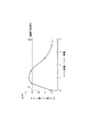
以上説明した装置において、両面プリントを連続して行ったときの、クリーニングブレード8a上のトナー積もり高さの推移を図7に示す。図7中の一点鎖線Aは、従来例の場合、即ち、転写ベルトへのパターントナー像の直接画像形成を入れない場合の推移を示しており、画像形成枚数の増加とともに積もり高さが上昇し、200枚を超えた時点で限界値8mmを超えて画像不良が発生した。
【0063】
これに対し、ジクザグの実線Bは、本実施例の場合で、画像形成100回ごと(両面プリントの記録材50枚ごと)に、転写ベルトへのパターントナー像の直接画像形成を加えており、パターントナー像を入れる直前までは積もり高さは上昇するが、入れた直後に高さが減少して、許容高さL以下に抑制され、画像不良も発生しなかった。ただし、許容高さLは、図2に示したクリーニングブレード8a上端から遮蔽板8eまでの距離であり、限界値S=8mmに対し余裕をとった値である。
【0064】
実施例2
図8は、本発明の画像形成装置の他の実施例を示す全体構成図である。
【0065】
実施例1では、転写ベルトを用いた画像形成装置に適用した例を説明したが、本発明は、図8のように、中間転写体を用いた画像形成装置に適用することもできる。図8において、図1に示したのと同じ機能を持つ部材については同一の符号を付して説明を省略する。
【0066】
本実施例において、画像形成装置はベルト状の中間転写体、即ち、中間転写ベルト140を有し、この中間転写ベルト140は、転写ベルトと同様、ポリイミド樹脂等からなるエンドレスのベルト体とされ、図中の矢印方向に回転する。各感光ドラム3(3a〜3d)上に形成された各色のトナー像は、それぞれの1次転写位置で転写帯電器24(24a〜24d)により、中間転写ベルト140上に順次重ねて転写され(1次転写)、次いで、中間転写ベルト140の回転にともない2次転写位置70に運ばれる。この中間転写ベルト上のトナー像の移動にタイミングを合わせて、記録材カセット10から記録材Pが2次転写位置に送られ、トナー像が記録材Pに接すると同時に転写帯電器80に転写バイアスが印加されて、トナー像が記録材Pに転写される。2次転写帯電手段80としては、導電性もしくは半導電性のゴムからなる転写ローラを用いた。
【0067】
又、画像形成装置は、画像形成装置の動作制御を行う制御手段100を備えている。
【0068】
転写を終えた記録材は、搬送部62により定着器9へ送られ、定着器9でトナー像が定着される。両面プリント時には、片面の1面目(表面)の定着を終えた記録材を搬送路67、66を経て再び2次転写位置70に送り、記録材の2面目(裏面)にトナー像を転写し、定着器9で定着する。
【0069】
2次転写手段の転写ローラ80には、定着オイルが付着した記録材の1面目に接するために、記録材から定着オイルが付着する。また転写ローラ80は、中間転写ベルト140に接するために、中間転写ベルト140上のかぶりトナーが付着する。この転写ローラ80に付着したオイルとかぶりトナーを除去するために、転写ローラ80にクリーニングブレード81を当接してある。
【0070】
このクリーニングブレード81においても、オイルとかぶりトナーが混合して、ブレードエッジ面への過剰なトナー積もりが生じてクリーナから溢れ出し、記録材へのトナー汚れが発生した。
【0071】
そこで、本実施例では、中間転写ベルト140上にパターントナー像を一定枚数ごとに形成し、これを記録材に2次転写せずに転写ローラ80に転写して、そのクリーニングブレードエッジ部に供給することにより、トナー積もり高さを抑制して、画像汚れを防止することができた。
【0072】
一方、中間転写ベルト140には、2次転写後に、中間転写ベルト140上に残留した2次転写残りトナーを除去するために、クリーニングブレード90が当接してある。中間転写ベルト140は転写ローラ80に接しているため、クリーニングブレード81からすり抜けたオイルの一部が中間転写ベルト140に転移し、クリーニングブレード90に送られる。
【0073】
このためクリーニングブレード90でもオイルとトナーが混合し、エッジ付近にトナー凝集を生じたが、ブレード90のエッジが重力方向下方に向くように中間転写ベルト140に当接してあるので、積もりトナーの一部がブレード90の廃トナー容器92に落下し、積もり高さは少なかった。しかし、容器92に回収したトナーがオイルを含んで粘度が上昇しているため、排出スクリュー91に付着して搬送されなくなる問題が発生した。
【0074】
そこで、本実施例では、中間転写ベルト140上にパターントナー像を一定枚数ごとに直接画像形成し、このトナーを記録材に2次転写せずにクリーニングブレード90に供給して容器92に入れ、容器92内のオイルを含んだ回収トナーの粘度を供給したトナーで下げた。これにより、回収トナーの排出スクリュー91による良好な搬送が可能となった。
【0075】
この場合、中間転写ベルト上のパターントナー像を2次転写させないために、パターントナー像が2次転写位置を通過中は、2次転写バイアスをOFFするか、あるいは通過中、中間転写ベルトから2次転写ローラ80を離間させるように構成してもよい。
【0076】
実施例3
図9は、中間転写体を用いた画像形成装置の別構成を示す。本発明は、本実施例における転写ベルトに当接するクリーニングブレードを有する構成においても適用することができる。
【0077】
中間転写体である転写ベルト211は、ローラ213と212に架けられ、図中矢印方向に搬送される。本実施例ではローラ212が駆動ローラとなっている。転写ベルト211の側面には、異なる色の画像形成が可能な画像形成部Pa、Pb、Pc、Pdが配置されている。画像形成部Paは、像担持体である感光ドラム203aの周囲に、現像装置202a、クリーニング装置204a、帯電装置205aが配置されている。帯電装置205aによって一様に帯電された感光ドラム203aの表面に、露光手段201aによって露光が行われ、潜像が形成される。この潜像は、現像装置202aで現像され、トナー像とされる。トナー像は、一次転写手段である転写ローラ206aによって、転写ベルト211上に転写される。画像形成部Pb、Pc、Pdも、画像形成部Paと同様な構成である。
【0078】
画像形成部Pa〜Pdによって各々形成された画像は、転写ベルト211上に順次重ねて転写され、カラー画像が形成される。
【0079】
カセット210から給紙された記録材は、ローラ213と二次転写ローラ218との間に形成される二次転写部に搬送され、転写ベルト211上の画像が記録材上に転写される。画像が転写された記録材は、定着ローラ209aと加圧ローラ209bとを有する定着手段209により定着される。定着ローラ209aには、離型剤であるオイルを塗布するオイル塗布部材209cが設けられている。
【0080】
又、画像形成装置は、本画像形成装置の動作制御を行う制御手段100を備えている。
【0081】
両面プリントの場合には、定着された記録材は、反転パス215に一旦導かれた後、再給紙パス216を通って給紙パスに合流し、再度二次転写部へと導かれる。
【0082】
本実施例では、転写ベルト211が駆動ローラ212に掛かっている部分において、クリーニング装置214のクリーニングブレード214aが当接し、転写残トナー等のクリーニングを行う。本実施例においても、ブレードエッジ面が上を向いて配置されているため、トナーがエッジ部に溜まり易い構成となっている。従って、オイルがブレードエッジ部に供給されることで、ブレードエッジ部での過剰なトナー積載が発生し、トナー溢れを発生することがある。
【0083】
従って、本実施例においても、この問題の発生を防止するために、例えば、転写ベルト211上にパターントナー像を一定枚数ごとに形成し、このトナーを記録材に2次転写せずにクリーニングブレード214aに供給し、エッジ部に溜まったオイルを含んだトナーの粘度を、供給したトナーで下げた。これにより、ブレードエッジ部での過剰なトナー積載を防止し、トナーが溢れることを防止することができた。
【0084】
実施例4
本実施例では、パターントナー像の供給量を少なくする方法を説明する。供給量を少なくすることは、トナー消費量を抑える観点から好ましく、トナーのランニングコストを低減できる効果もある。
【0085】
図1の画像形成装置において、クリーニングブレード8aにおけるトナー積もり高さは、特にクリーニングブレード8aに常時オイルが供給される両面プリント時に上昇が激しい。これに対し、両面プリント終了後の片面プリン時には、転写ベルト30へのオイル供給がなくなり、且つ、転写ベルト上のオイルがパターントナー像に吸収されて、パターントナー像とともにクリーニングブレード8aで除去、回収されていくため、オイル混合比が徐々に低下し、積もり高さも減少していく。
【0086】
図10は、パターントナー像を供給しながら両面プリントを十分な枚数を行い、最後にパターントナー像を供給し終えた後、片面プリントを連続して行ったときの、片面時の積もり高さの推移である。パターントナー像の供給間隔は、実施例1と同じ100枚ごととした。
【0087】
図10に示すように、積もり高さの上昇勾配は徐々に低下し、最終的な積もり高さは、ほぼ一定値(転写ベルト上にオイルが存在しないときの積もり高さと同じ2mm)を推移するようになった。この結果から分かるように、片面プリント時は、上昇勾配が低下するので、供給間隔を両面時より長く設定できる。さらに、積もり高さが低下していくので、供給間隔を徐々に延長し、最終的には供給を止めることが可能である。
【0088】
図11に両面プリントを所定枚数行った後の、片面プリント時のトナー供給間隔の設定方法を示す。
【0089】
両面プリントを100枚行った後、片面プリント時のトナー供給ポイントは、100枚時、300枚時、600枚時、1000枚時となっており、片面プリント枚数が増加するに従い、トナー供給間隔は徐々に広がっていくようになっている。つまり、実質的なトナー供給量を減らしていくことになる。片面プリント開始直後の100枚目の時点では、それ以前に両面プリントが多く行われた後であり、クリーニングブレードエッジ部でのオイル蓄積量がまだ多いため、両面プリント時と同じ100枚後のトナー供給を行う。これ以降は片面プリントが続き、オイル供給もないため、トナー積もりも軽減され、トナー供給間隔を広げることができる。そして、更に片面プリント枚数が増加するにつれ、トナー積もりも一層軽減されていき、トナー供給間隔も更に広げることが可能になる。そして、トナー供給間隔が400枚となる片面プリント1000枚時点でトナー供給が行われた後は、ブレードエッジ部でのトナー積載高さは、もはや問題を発生するレベルにはならないため、これ以降のトナー供給は不要となる。
【0090】
更に、片面プリント前の両面プリントの枚数が少ないほど、クリーニングブレードエッジ部のオイル蓄積量も減るため、以下の例のように、トナー供給間隔もそれに応じて広げることが可能となる。
【0091】
両面プリントを50枚行った後の片面プリント時のトナー供給ポイントは、200枚時、500枚時、900枚時となっており、900枚時以降はトナー供給は行われない。
【0092】
また、両面プリントを10枚行った後の片面プリント時のトナー供給ポイントは、300枚時、700枚時となっており、700枚時以降はトナー供給は行われない。
【0093】
上記は、供給量を少なくする方法として、供給間隔を長く設定した。その他に、例えば供給間隔を両面プリント時と同じ100枚ごとに固定して、片面プリント枚数に応じて1回あたりのトナー供給量を減らしていってもよい。
【0094】
図12に、両面プリントを所定枚数行った後の、片面プリント時のトナー供給量(パターントナー像の濃度レベル)の設定方法を示す。
【0095】
両面プリント100枚後の片面プリント時に、100枚おきにトナー供給を行う際、プリント枚数が増加するに従いパターントナー像の濃度レベルを、先の実施例で示した64レベルから徐々に低下させている。そして600枚時点で16レベルの濃度でトナー供給を行った後は、トナー供給を行わない。
【0096】
両面プリント50枚後は、56レベルの濃度で開始し、500枚時点で16レベルのトナー供給を行った後は、トナー供給を行わない。
【0097】
両面プリント10枚後は、48レベルの濃度で開始し、400枚時点で6レベルのトナー供給を行った後は、トナー供給を行わない。
【0098】
このように、片面プリント前の両面プリント枚数が少ないほど、ブレードエッジ部におけるトナー堆積は軽微になっていくので、100枚ごとのトナー供給量、及び総トナー供給量を少なくすることができる。
【0099】
なお、本実施例においては、図1構成の画像形成装置について述べたが、図8や図9に示した画像形成装置においても、同様な効果を得ることができる。
【0100】
実施例5
本実施例では、パターントナー像の供給量を少なくする他の方法について説明する。
【0101】
トナー積もり高さが転写ベルトに付着したオイル量に依存することは、既に述べた通りであるが、このオイル量が湿度によって変化することが分かった。即ち、湿度が低いほど、離型剤オイルとして使用するジメチルシリコーンオイルの低分子量成分が揮発し、記録材、転写ベルト及びクリーニングブレード上のオイル量が減少する。このため、同じ枚数の両面プリントを行っても、低湿環境では高湿環境ほどトナー積もり高さが上昇しないことが分かった。この現象を利用し、低湿環境でのパターントナー像のトナー量を少なくすることが可能である。
【0102】
図13は、画像形成装置内の雰囲気の水分量(絶対水分量、つまり空気1000cc中に含まれる水の重量)に対するパターントナー像の濃度レベルの両面プリント時の設定を示す。
【0103】
水分量18g以上の高湿環境では、トナー積もり高さを抑えるために、実施例1と同じ濃度(64レベル)のパターントナー像が必要である。一方、水分量5g以下の低湿環境では、半分の濃度(32レベル)でもトナー積もり高さを抑えることができた。5gと18gの中間の湿度の環境では、濃度を線形補間した設定で効果が得られた。
【0104】
本実施例では、装置内の水分量を検知する手段として、図1の画像形成装置の転写ベルト30付近に、温度及び相対湿度を検知する環境センサ60を設け、環境センサ60で検知した温度及び相対湿度から水分量を算出して、水分量の結果に応じて、図13に基づき、濃度レベルを切り換えるようにした。
【0105】
これにより、画像形成装置内の雰囲気の水分量の変化に応じて、トナー積もり高さを抑えると同時に、常に最少量のトナー消費を維持することができた。
【0106】
上記では、検出した水分量に応じて、供給トナーの濃度レベルを変える例について説明したが、検出した水分量に応じて、トナー供給間隔を変える方法でも同様な効果を得ることができる。即ち、水分量が低くなるに従い、トナー供給間隔を広げる制御を行う。
【0107】
例えば、水分量が18g以上の場合はトナーが堆積し易いので、100枚おきにトナー供給を行い、5g以下の場合には200枚おきに行い、5gと18gの中間の水分量の場合には線形補間した設定にすればよい。
【0108】
なお、上記実施例中で示したトナー供給間隔、供給トナー濃度レベル、検出水分量等の具体的な数値は一例にすぎず、装置構成によりそれぞれ最適な値が存在するものであり、これらの値に限定されるものではない。
【0109】
なお、本実施例においては、図1構成の画像形成装置について述べたが、図8や図9に示した画像形成装置においても、同様な効果を得ることができる。
【0110】
【発明の効果】
以上説明したように、本発明によれば、両面プリントが可能な画像形成装置において、定期的に記録材搬送部材や中間転写体や転写部材へ直接トナー画像の形成を行って、そのトナーを記録材搬送部材のクリーニングブレード、中間転写体のクリーニングブレード、転写部材のクリーニングブレードへ供給するようにしたので、定着時に記録材に付着したオイルが両面プリント時に記録材搬送部材や中間転写体や転写部材に転移することが原因で生じる、これらクリーニングブレードへのトナーの積み上がりを防止でき、機内汚染や記録材の裏汚れ等の問題を防止することができる。
【図面の簡単な説明】
【図1】本発明の画像形成装置の一実施例を示す全体構成図である。
【図2】図1の画像形成装置に設置された転写ベルトのクリーナを示す断面図である。
【図3】図2のクリーナのクリーニングブレード上のトナーの積もり高さとトナーのオイル混合比との関係を示すグラフである。
【図4】図1の実施例で転写ベルト上に直接画像形成したパターントナー像とクリーニングブレード及び記録材等との寸法関係を示す模式図である。
【図5】図4のパターントナー像の濃度とトナー積もり高さの関係を示すグラフである。
【図6】図4のパターントナー像形成の動作タイミングを示す図である。
【図7】画像形成枚数に対するトナー積もり高さの推移を示すグラフである。
【図8】本発明の画像形成装置の他の実施例を示す全体構成図である。
【図9】本発明の画像形成装置の他の実施例を示す全体構成図である。
【図10】片面プリント時の画像形成枚数に対するトナー積もり高さの推移を示すグラフである。
【図11】両面プリント後の片面プリント時におけるトナー供給間隔の変化を表した図である。
【図12】両面プリント後の片面プリント時における供給トナー濃度の変化を表した図である。
【図13】水分量に対するパターントナー像の濃度設定法を示すグラフである。
【符号の説明】
Pa〜Pd 画像形成部
3a〜3d 感光ドラム
8 転写ベルトクリーナ
8a クリーニングブレード(清掃手段)
9 定着器(定着手段)
24a〜24d 転写帯電器
30 転写ベルト(記録材搬送部材)
64 ガイド部材
80 2次転写ローラ(転写部材)
8a、81、90、214a クリーニングブレード
91 排出スクリュー
140、211 中間転写ベルト(中間転写体)[0001]
BACKGROUND OF THE INVENTION
The present invention relates to an image forming apparatus capable of performing double-sided image formation using an electrophotographic method and performing image formation on the back side of the same recording material after image formation is performed on one side of the recording material.
[0002]
[Prior art]
Conventionally, a plurality of image forming units using an electrophotographic method are provided, and toner images of different colors are formed in each image forming unit, and the toner images are sequentially superimposed and transferred onto the same recording material for recording. Various image forming apparatuses for forming a color image on a material have been proposed. There has also been proposed a color copier for performing color high-speed recording, which includes a transfer belt, which is an endless belt-like recording material conveying member, and in which a plurality of image forming units are linearly arranged along the transfer belt.
[0003]
An example of this color copying machine will be briefly described with reference to FIG. 1. First, second, third, and fourth image forming portions Pa, Pb, Pc, and Pd are arranged in the apparatus, and image formation is performed. The unit includes electrophotographic
[0004]
In such an image forming apparatus, in order to prevent the toner on the recording material from adhering to the
[0005]
Further, on the
[0006]
In the configuration shown in FIG. 1, the
[0007]
Such an arrangement of the cleaning blade makes it easy to hold the toner on the blade edge surface, and by this toner holding, a stable slidability is obtained at the contact portion with the transfer belt, and a toner polishing effect is also added. An improvement in cleaning performance can be obtained.
[0008]
[Problems to be solved by the invention]
However, in such an image forming apparatus, when image formation is performed on both surfaces of the recording material, there is a problem that toner is excessively accumulated on the edge of the
[0009]
As a result of investigations by the present inventors, it has been found that the toner accumulates on the edge of the
[0010]
The above problems are caused by the above-described configuration of the intermediate transfer body even in an intermediate transfer type image forming apparatus that temporarily transfers the toner image on the photosensitive drum to the intermediate transfer body and then transfers the toner image from the intermediate transfer body to the recording material. This occurs in the same manner when the above cleaning device is used.
[0011]
An object of the present invention is to prevent toner overflow due to excessive accumulation of toner on a cleaning member with respect to a recording material carrier, an intermediate transfer member, or a transfer member, and eliminate problems such as in-machine contamination and recording material back contamination. A forming apparatus is provided.
[0012]
[Means for Solving the Problems]
The above object is achieved by the image forming apparatus according to the present invention. In summary, the present invention provides an image forming unit that forms a toner image, a recording material conveying member that carries and conveys a recording material, a cleaning unit that includes a cleaning blade that contacts the surface of the recording material conveying member, and a mold release An image forming apparatus capable of forming an image on a surface opposite to a toner image transfer surface with respect to a recording material subjected to a fixing operation by the fixing unit. In this case, the recording material conveyance member is closer to the abutting portion with respect to the recording material conveyance member than the corresponding contact portion rotation The cleaning blade is disposed so that the edge surface of the cleaning blade facing the upstream side in the direction is directed upward or downward with respect to the direction of gravity, and the toner image for supply to the cleaning means formed by the image forming means Is directly transferred onto the recording material conveying member, and the recording material conveying member is Rotate Control means for controlling the supply toner image transferred onto the recording material conveying member to be supplied to the cleaning means,
(1) The supply operation of the supply toner image is intermittently performed every time a predetermined number of images are formed on a recording material, and the image formation is performed as a series of operations on a plurality of recording materials. When the predetermined number of sheets is reached during the series of operations, the supply operation is performed after the series of operations is completed.
(2) The supply operation of the supply toner image is intermittently performed every time a predetermined number of images are formed on the recording material, and the single-sided image on the recording material is more than when the double-sided image is formed on the recording material. At the time of formation, the value of the predetermined number is larger,
(3) The supplying operation of the toner image for supply is intermittently performed every time a predetermined number of images are formed on the recording material, and when forming a single-sided image on the recording material, Increasing the toner supply interval by increasing the value of the predetermined number,
(4) The supply operation of the supply toner image is intermittently performed every time a predetermined number of images are formed on the recording material, and the number of recording materials on which double-sided image formation is performed. When there are few Thereafter, the value of the predetermined number at the time of single-sided image formation on the recording material is set. big Or,
(5) The supply operation of the supply toner image is intermittently performed every time a predetermined number of images are formed on the recording material, and the
(6) The supply operation of the supply toner image is intermittently performed every time a predetermined number of images are formed on the recording material, and the number of recording materials on which double-sided image formation is performed. When there are few Thereafter, the toner supply amount per one supply operation at the time of single-sided image formation on the recording material is determined. Less To
An image forming apparatus characterized by the above.
[0013]
According to another aspect of the present invention, an image forming unit that forms a toner image, an intermediate transfer member that carries the toner image formed by the image forming unit, and a toner image that is carried on the intermediate transfer member are recorded. A fixing unit including a transfer unit that transfers to a material, a cleaning unit that includes a cleaning blade that contacts the surface of the intermediate transfer member, and a fixing unit that includes a fixing member to which a release agent is applied. In the image forming apparatus capable of forming an image on the surface opposite to the toner image transfer surface with respect to the recording material received, the intermediate transfer member is closer to the contact portion with respect to the intermediate transfer member than the corresponding contact portion. rotation The cleaning blade is disposed so that the edge surface of the cleaning blade facing the upstream side in the direction is directed upward or downward with respect to the direction of gravity, and the toner image for supply to the cleaning means formed by the image forming means On the intermediate transfer member, and the intermediate transfer member Rotate A control means for controlling the supply toner image carried thereon to be supplied to the cleaning means,
(1) The supply operation of the supply toner image is intermittently performed every time a predetermined number of images are formed on a recording material, and the image formation is performed as a series of operations on a plurality of recording materials. When the predetermined number of sheets is reached during the series of operations, the supply operation is performed after the series of operations is completed.
(2) The supply operation of the supply toner image is intermittently performed every time a predetermined number of images are formed on the recording material, and the single-sided image on the recording material is more than when the double-sided image is formed on the recording material. At the time of formation, the value of the predetermined number is larger,
(3) The supplying operation of the toner image for supply is intermittently performed every time a predetermined number of images are formed on the recording material, and when forming a single-sided image on the recording material, Increasing the toner supply interval by increasing the value of the predetermined number,
(4) The supply operation of the supply toner image is intermittently performed every time a predetermined number of images are formed on the recording material, and the number of recording materials on which double-sided image formation is performed. When there are few Thereafter, the value of the predetermined number at the time of single-sided image formation on the recording material is set. big Or,
(5) The supply operation of the supply toner image is intermittently performed every time a predetermined number of images are formed on the recording material, and the
(6) The supply operation of the supply toner image is intermittently performed every time a predetermined number of images are formed on the recording material, and the number of recording materials on which double-sided image formation is performed. When there are few Thereafter, the toner supply amount per one supply operation at the time of single-sided image formation on the recording material is determined. Less To
An image forming apparatus is provided.
[0014]
According to still another aspect of the present invention, an image forming unit that forms a toner image, a transfer member that transfers the toner image formed by the image forming unit to a recording material, and a cleaning blade that contacts the surface of the transfer member A recording unit having a fixing member coated with a release agent, and a recording material subjected to a fixing operation by the fixing unit on a surface opposite to the toner image transfer surface, In an image forming apparatus capable of forming an image, the transfer member is closer to a contact portion with respect to the transfer member than the corresponding contact portion. rotation The cleaning blade is disposed so that the edge surface of the cleaning blade facing the upstream side in the direction is directed upward or downward with respect to the direction of gravity, and the toner image for supply to the cleaning means formed by the image forming means Is directly transferred onto the transfer member, and the transfer member Rotate Control means for controlling the supply toner image to be supplied to the cleaning means.
(1) The supply operation of the supply toner image is intermittently performed every time a predetermined number of images are formed on a recording material, and the image formation is performed as a series of operations on a plurality of recording materials. When the predetermined number of sheets is reached during the series of operations, the supply operation is performed after the series of operations is completed.
(2) The supply operation of the supply toner image is intermittently performed every time a predetermined number of images are formed on the recording material, and the single-sided image on the recording material is more than when the double-sided image is formed on the recording material. At the time of formation, the value of the predetermined number is larger,
(3) The supplying operation of the toner image for supply is intermittently performed every time a predetermined number of images are formed on the recording material, and when forming a single-sided image on the recording material, Increasing the toner supply interval by increasing the value of the predetermined number,
(4) The supply operation of the supply toner image is intermittently performed every time a predetermined number of images are formed on the recording material, and the number of recording materials on which double-sided image formation is performed. When there are few Thereafter, the value of the predetermined number at the time of single-sided image formation on the recording material is set. big Or,
(5) The supply operation of the supply toner image is intermittently performed every time a predetermined number of images are formed on the recording material, and the
(6) The supply operation of the supply toner image is intermittently performed every time a predetermined number of images are formed on the recording material, and the number of recording materials on which double-sided image formation is performed. When there are few Thereafter, the toner supply amount per one supply operation at the time of single-sided image formation on the recording material is determined. Less To
An image forming apparatus is provided.
[0015]
According to the present invention, in an image forming apparatus capable of double-sided printing, a toner image is directly formed on a recording material conveyance member, an intermediate transfer member, or a transfer member on a regular basis, and the toner is removed from the recording material conveyance member cleaning blade. This is because the oil attached to the recording material during fixing is transferred to the recording material conveying member, the intermediate transfer member, and the transfer member during double-sided printing because it is supplied to the cleaning blade of the intermediate transfer member and the cleaning blade of the transfer member. Thus, toner accumulation on these cleaning blades can be prevented, and problems such as in-machine contamination and backside contamination of the recording material can be prevented.
[0016]
DETAILED DESCRIPTION OF THE INVENTION
The image forming apparatus according to the present invention will be described below in more detail with reference to the drawings.
[0017]
Example 1
FIG. 1 is an overall configuration diagram showing an embodiment of an image forming apparatus of the present invention, which is configured in a four-color full-color copying machine.
[0018]
The copying machine includes a plurality of image forming portions Pa, Pb, Pc, and Pd along a
[0019]
Each of the
[0020]
The developing
[0021]
A
[0022]
The
[0023]
The
[0024]
By this transfer, the recording material P is firmly held on the
[0025]
As the adsorption charger 5, a non-contact charger such as a corona charger or a contact charger using a charging member such as a blade, a roller, or a brush is used.
[0026]
Similarly, the transfer charger 24 (24a to 24d) may be a non-contact charger such as a corona charger, or a contact charger using a charging member such as a blade, roller, or brush. The non-contact charger has problems such as generation of ozone, weakness due to fluctuations in the temperature and humidity environment of the atmosphere because it is charged via air, and an image being not stably formed. On the other hand, the contact charger has advantages such as ozone-less, resistance to temperature and humidity fluctuations, and high image quality.
[0027]
In some cases, the static elimination needles 7a to 7d are provided to stabilize the transferability. The static elimination needles 7a to 7d are not in contact with the
[0028]
Image formation and transfer of the second to fourth image forming units Pb to Pd are performed in the same manner as the first image forming unit Pa. The recording material P on which the toner images of four colors are superimposed and transferred in this way is then neutralized by the separation
[0029]
The separated recording material P is conveyed to the fixing device 9 as a fixing unit by the
[0030]
The fixing device 9 includes a fixing
[0031]
The recording material P to which the four color toner images are transferred is mixed with the toner image and fixed to the recording material P by fixing, and is formed into a full-color copy image, and then discharged to the
[0032]
After the transfer, the
[0033]
It is known that the transfer charger 24 stabilizes the image when the current contributing to the transfer is kept constant at an appropriate value. Therefore, it is common to perform constant current control so that a constant current can be obtained even when the volume resistivity changes depending on the type of recording material (thickness, material, etc.) and moisture absorption conditions.
[0034]
The image forming apparatus also includes a
[0035]
In the single-sided printing process, the toner image is transferred to the recording material P conveyed from the
[0036]
When fixing, the recording material P comes into contact with the fixing
[0037]
When paper is used as the recording material P, the fixing oil adhering to the white background where there is no toner image on the paper is almost absorbed by the paper and the amount of oil remaining on the surface of the paper is small. However, the oil adhering to the portion where the toner image is present only absorbs a part of the adhering oil into the paper, and most of the oil remains on the surface of the toner image. Become. Therefore, the amount of oil adhering to the
[0038]
Next, the transfer belt cleaner will be described with reference to FIG.
[0039]
As described above, the
[0040]
The
[0041]
As described above, the cleaning blade is brought into contact with the portion where the
[0042]
The fog toner R on the
[0043]
The toner collected in the
[0044]
In the image forming apparatus provided with such a
[0045]
As a result of investigations on the cause of the accumulation, the fixing oil F and the fog toner R adhering to the
[0046]
FIG. 3 shows the result of measuring the toner pile height by changing the mixing ratio (weight ratio) of the fixing oil adhering to the recording material and the fog toner on the transfer belt. Here, the toner accumulation height is the distance X shown in FIG. 2, that is, the distance from the upper end of the
[0047]
As can be seen from FIG. 3, the toner pile height shows a maximum value of 8 mm or more when the ratio of the oil weight to the fog toner weight is 0.5 to 1.5, and when the ratio is smaller or larger than this, The toner pile is low.
[0048]
This is because when the amount of oil is a very small amount of 0.5 or less, the toner mixed with the oil remains in a shape close to a dry powder, and the toner collapses on the
[0049]
The weight ratio of the normal amount of oil and the amount of toner supplied to the
[0050]
In order to prevent image defects, it is only necessary to reduce the toner pile height on the
[0051]
The toner pile height does not change because even if the amount of oil on the
[0052]
Therefore, when the toner accumulates on the cleaning blade edge surface A to such an extent that the toner does not overflow from the cleaning device, a toner image is formed on the
[0053]
Further, the supply of the toner image causes the toner image to enter between the accumulated toner T on the
[0054]
FIG. 4 shows a toner image for directly forming an image on the transfer belt. The recording material P is adsorbed and conveyed almost at the center of the belt in a direction perpendicular to the running direction of the
[0055]
As described above, the pattern toner image Q is stacked on the
[0056]
As a result of examining the toner amount of the pattern toner image Q, it was found that an optimum toner amount exists. Explaining with reference to FIG. 5, FIG. 5 shows the result of examining the accumulated height of the toner when the pattern toner image is supplied for every fixed number of double-sided prints by changing the density level of the pattern toner image. is there.
[0057]
As the pattern toner image, a solid image or a halftone image having a uniform density regardless of the location was used. Since the total toner amount of the pattern toner image is preferably as small as possible from the viewpoint of toner consumption, the total toner amount of the pattern toner image is 1 mg / cm. 2 The width r in the transfer belt running direction was changed while changing the density. The vertical width t is constant at 300 mm. According to this, the solid image has a total toner amount = 1 mg / cm. 2 R = 12.5 mm and t = 300 mm. The concentration level was changed from 0 to 256 level.
[0058]
As shown in FIG. 5, if the density of the pattern toner image is too low, there is no effect of destroying the accumulated toner, and the accumulated height is minimized at 64 halftone levels (r = 50 mm). It was found that the pile height gradually increased when raised. The reason why the toner stack height increases on the high density side is that the toner layer of the pattern toner image is thick, so the toner on the upper layer does not mix well with the toner stack on the blade edge, and the cleaner container does not absorb oil It was found that it dropped into 8c and a sufficient accumulation toner removal effect could not be obtained. From these results, in the case of this configuration, setting the density of the pattern toner image to 64 levels was effective in reducing the pile height and reducing the toner consumption.
[0059]
FIG. 6 shows the operation timing of each part for forming the pattern toner image of the toner image on the transfer belt. This operation timing is based on the transfer position of any transfer charger among the
[0060]
A counter forming part of the
[0061]
The counter is reset to zero when the pattern toner image is formed, then counts the number of images formed again, resets to zero again when the next pattern toner image is formed, and thereafter repeats the same operation. In addition to this, as a timing for forming a pattern toner image, it may be put in the middle of the rotation of the belt immediately before the end of the job that has reached n sheets, without being put in the middle of the job (image formation in which a plurality of sheets are continuous) ( Q2 in FIG. Alternatively, the belt may be rotated during the rotation of the belt immediately before the start of image formation for the next job after n jobs.
[0062]
FIG. 7 shows the transition of the toner pile height on the
[0063]
On the other hand, the zigzag solid line B in the present embodiment adds the direct image formation of the pattern toner image to the transfer belt every 100 image formations (every 50 recording materials for double-sided printing). The pile height increased immediately before the pattern toner image was put, but the height was reduced just after the pattern toner image was put, it was suppressed to the allowable height L or less, and no image defect occurred. However, the allowable height L is the distance from the upper end of the
[0064]
Example 2
FIG. 8 is an overall configuration diagram showing another embodiment of the image forming apparatus of the present invention.
[0065]
In the first embodiment, an example in which the image forming apparatus is applied to the transfer belt has been described. However, the present invention can also be applied to an image forming apparatus using an intermediate transfer member as shown in FIG. In FIG. 8, members having the same functions as those shown in FIG.
[0066]
In this embodiment, the image forming apparatus includes a belt-shaped intermediate transfer body, that is, an
[0067]
The image forming apparatus also includes a
[0068]
After the transfer, the recording material is sent to the fixing device 9 by the
[0069]
The fixing oil adheres from the recording material to the
[0070]
Also in the
[0071]
Therefore, in this embodiment, a pattern toner image is formed on the
[0072]
On the other hand, a
[0073]
For this reason, oil and toner are mixed in the
[0074]
Therefore, in this embodiment, a pattern toner image is directly formed on the
[0075]
In this case, in order to prevent the pattern toner image on the intermediate transfer belt from being secondarily transferred, the secondary transfer bias is turned off while the pattern toner image passes the secondary transfer position, or the pattern toner image is removed from the intermediate transfer belt while passing. The
[0076]
Example 3
FIG. 9 shows another configuration of the image forming apparatus using the intermediate transfer member. The present invention can also be applied to a configuration having a cleaning blade in contact with the transfer belt in this embodiment.
[0077]
A
[0078]
The images respectively formed by the image forming units Pa to Pd are sequentially transferred on the
[0079]
The recording material fed from the
[0080]
The image forming apparatus also includes a
[0081]
In the case of double-sided printing, the fixed recording material is once guided to the reversing
[0082]
In this embodiment, the
[0083]
Therefore, also in this embodiment, in order to prevent the occurrence of this problem, for example, a pattern toner image is formed on the
[0084]
Example 4
In this embodiment, a method for reducing the supply amount of the pattern toner image will be described. Decreasing the supply amount is preferable from the viewpoint of suppressing toner consumption, and has an effect of reducing the running cost of the toner.
[0085]
In the image forming apparatus of FIG. 1, the toner pile height in the
[0086]
FIG. 10 shows the accumulated height of one side when a sufficient number of double-sided prints are made while supplying the pattern toner image, and the single-sided printing is continuously performed after the last supply of the pattern toner image. It is a transition. The supply interval of the pattern toner images was set to every 100 sheets as in the first embodiment.
[0087]
As shown in FIG. 10, the rising gradient of the pile height gradually decreases, and the final pile height changes to a substantially constant value (2 mm, which is the same as the pile height when no oil is present on the transfer belt). It became so. As can be seen from this result, since the ascending gradient decreases during single-sided printing, the supply interval can be set longer than when double-sided. Furthermore, since the pile height decreases, it is possible to gradually extend the supply interval and finally stop the supply.
[0088]
FIG. 11 shows a method for setting the toner supply interval during single-sided printing after a predetermined number of double-sided prints.
[0089]
After 100 double-sided prints, the toner supply points for single-sided printing are 100, 300, 600, and 1000. As the number of single-sided printed sheets increases, the toner supply interval increases. It is gradually spreading. That is, the substantial toner supply amount is reduced. At the time of the 100th sheet immediately after the start of single-sided printing, the amount of oil accumulated at the cleaning blade edge is still large after a large amount of double-sided printing before that time. Supply. Thereafter, single-sided printing continues and there is no oil supply, so toner accumulation is reduced and the toner supply interval can be extended. As the number of single-sided prints further increases, the toner accumulation is further reduced, and the toner supply interval can be further increased. After the toner is supplied at the time of 1000 sheets of single-sided printing where the toner supply interval is 400 sheets, the toner stacking height at the blade edge portion is no longer at a level causing a problem. There is no need to supply toner.
[0090]
Further, the smaller the number of double-sided prints before single-sided printing, the smaller the oil accumulation amount at the cleaning blade edge portion. Therefore, as in the following example, the toner supply interval can be increased accordingly.
[0091]
The toner supply points for single-sided printing after 50 double-sided printings are 200, 500, and 900, and no toner is supplied after 900.
[0092]
Further, the toner supply points at the time of single-sided printing after 10 double-sided printings are at 300 sheets and 700 sheets, and toner supply is not performed after 700 sheets.
[0093]
In the above, as a method of reducing the supply amount, the supply interval is set long. In addition, for example, the supply interval may be fixed every 100 sheets as in the case of duplex printing, and the toner supply amount per time may be reduced according to the number of single-sided prints.
[0094]
FIG. 12 shows a method for setting the toner supply amount (pattern toner image density level) during single-sided printing after performing a predetermined number of double-sided printings.
[0095]
At the time of one-sided printing after 100 double-sided printing, when toner is supplied every 100 sheets, the density level of the pattern toner image is gradually lowered from the 64 level shown in the previous embodiment as the number of printed sheets increases. . Then, after supplying toner at a density of 16 levels at the time of 600 sheets, toner supply is not performed.
[0096]
After 50 double-sided prints, it starts at a density of 56 levels. After supplying 16 levels of toner at the time of 500 sheets, no toner is supplied.
[0097]
After 10 double-sided prints, it starts at a density of 48 levels, and after supplying 6 levels of toner at the time of 400 sheets, no toner is supplied.
[0098]
As described above, as the number of double-sided printed sheets before single-sided printing is smaller, toner accumulation at the blade edge portion becomes lighter. Therefore, the toner supply amount and the total toner supply amount for every 100 sheets can be reduced.
[0099]
In the present embodiment, the image forming apparatus having the configuration shown in FIG. 1 has been described. However, similar effects can be obtained in the image forming apparatuses shown in FIGS.
[0100]
Example 5
In this embodiment, another method for reducing the supply amount of the pattern toner image will be described.
[0101]
As described above, the toner pile height depends on the amount of oil adhering to the transfer belt, but it has been found that the amount of oil varies depending on the humidity. That is, as the humidity is lower, the low molecular weight component of dimethyl silicone oil used as the release agent oil volatilizes, and the amount of oil on the recording material, transfer belt and cleaning blade decreases. For this reason, it was found that even if the same number of double-sided prints were performed, the toner accumulation height did not increase in a low humidity environment as in a high humidity environment. By utilizing this phenomenon, it is possible to reduce the toner amount of the pattern toner image in a low humidity environment.
[0102]
FIG. 13 shows the setting at the time of duplex printing of the density level of the pattern toner image with respect to the moisture content of the atmosphere in the image forming apparatus (absolute moisture content, that is, the weight of water contained in 1000 cc of air).
[0103]
In a high-humidity environment with a moisture content of 18 g or more, a patterned toner image having the same density (64 levels) as in Example 1 is necessary to suppress the toner accumulation height. On the other hand, in a low humidity environment with a water content of 5 g or less, the toner pile height could be suppressed even at half the density (32 levels). In an environment with an intermediate humidity between 5 g and 18 g, the effect was obtained with a linear interpolation of the concentration.
[0104]
In this embodiment, an
[0105]
As a result, the toner accumulation height can be suppressed according to the change in the moisture content of the atmosphere in the image forming apparatus, and at the same time, the minimum amount of toner consumption can be maintained.
[0106]
In the above description, the example in which the concentration level of the supplied toner is changed according to the detected amount of water has been described. However, the same effect can be obtained by a method of changing the toner supply interval according to the detected amount of water. That is, control is performed to widen the toner supply interval as the amount of water decreases.
[0107]
For example, toner tends to accumulate when the amount of water is 18 g or more. Therefore, toner is supplied every 100 sheets, and every 200 sheets when the amount is 5 g or less, and when the water amount is between 5 g and 18 g. A linear interpolation setting may be used.
[0108]
The specific numerical values such as the toner supply interval, supplied toner concentration level, and detected water amount shown in the above embodiments are merely examples, and there are optimum values depending on the apparatus configuration. It is not limited to.
[0109]
In this embodiment, the image forming apparatus having the configuration shown in FIG. 1 has been described. However, similar effects can be obtained in the image forming apparatuses shown in FIGS.
[0110]
【The invention's effect】
As described above, according to the present invention, in an image forming apparatus capable of duplex printing, a toner image is directly formed on a recording material conveying member, an intermediate transfer member, or a transfer member on a regular basis, and the toner is recorded. Since it is supplied to the cleaning blade of the material conveying member, the cleaning blade of the intermediate transfer member, and the cleaning blade of the transfer member, the oil adhering to the recording material at the time of fixing is the recording material conveying member, the intermediate transfer member, and the transfer member at the time of duplex printing. Therefore, it is possible to prevent toner from accumulating on the cleaning blade, which is caused by the transfer to the toner, and to prevent problems such as in-machine contamination and backside contamination of the recording material.
[Brief description of the drawings]
FIG. 1 is an overall configuration diagram showing an embodiment of an image forming apparatus of the present invention.
2 is a cross-sectional view showing a transfer belt cleaner installed in the image forming apparatus of FIG. 1. FIG.
3 is a graph showing the relationship between the toner pile height on the cleaning blade of the cleaner shown in FIG. 2 and the oil mixing ratio of the toner.
4 is a schematic diagram showing a dimensional relationship between a pattern toner image directly formed on a transfer belt in the embodiment of FIG. 1, a cleaning blade, a recording material, and the like.
5 is a graph showing the relationship between the density of the pattern toner image and the toner accumulation height in FIG.
6 is a diagram illustrating operation timing of pattern toner image formation in FIG. 4. FIG.
FIG. 7 is a graph showing a transition of toner accumulation height with respect to the number of formed images.
FIG. 8 is an overall configuration diagram showing another embodiment of the image forming apparatus of the present invention.
FIG. 9 is an overall configuration diagram showing another embodiment of the image forming apparatus of the present invention.
FIG. 10 is a graph showing a transition of toner accumulation height with respect to the number of images formed during single-sided printing.
FIG. 11 is a diagram illustrating a change in toner supply interval during single-sided printing after double-sided printing.
FIG. 12 is a diagram illustrating a change in supply toner density during single-sided printing after double-sided printing.
FIG. 13 is a graph illustrating a pattern toner image density setting method with respect to moisture content.
[Explanation of symbols]
Pa to Pd Image forming unit
3a-3d Photosensitive drum
8 Transfer belt cleaner
8a Cleaning blade (cleaning means)
9 Fixing device (fixing means)
24a-24d Transfer charger
30 Transfer belt (recording material conveying member)
64 Guide member
80 Secondary transfer roller (transfer member)
8a, 81, 90, 214a Cleaning blade
91 Discharge screw
140, 211 Intermediate transfer belt (intermediate transfer member)
Claims (25)
記録材を担持搬送する記録材搬送部材と、
該記録材搬送部材の表面に当接するクリーニングブレードを備える清掃手段と、
離型剤が塗布された定着部材を備える定着手段と、を有し、
前記定着手段による定着動作を受けた記録材に対し、トナー像転写面とは反対の面に、画像形成が可能な画像形成装置において、
前記記録材搬送部材に対する当接部に近接し、該当接部よりも記録材搬送部材回転方向の上流側に面するクリーニングブレードのエッジ面が、重力方向に対して上または下を向くように、前記クリーニングブレードは配置され、
前記像形成手段が形成した、清掃手段への供給用トナー像を、前記記録材搬送部材の上に直接転写し、前記記録材搬送部材が回転することで該記録材搬送部材上に転写された該供給用トナー像を前記清掃手段に供給するよう制御する制御手段、を備え、
前記供給用トナー像の供給動作は、間欠的に、記録材への画像形成が所定枚数行われるごとに行われ、前記画像形成を、複数の記録材に対する画像形成を一連の動作として行う時、該一連の動作中に前記所定枚数に到達した場合、該一連の動作終了後に前記供給動作を行うことを特徴とする画像形成装置。An image forming means for forming a toner image;
A recording material conveying member for carrying and conveying the recording material;
Cleaning means comprising a cleaning blade that contacts the surface of the recording material conveying member;
Fixing means comprising a fixing member coated with a release agent,
In an image forming apparatus capable of forming an image on a surface opposite to a toner image transfer surface with respect to a recording material subjected to a fixing operation by the fixing unit,
The edge surface of the cleaning blade that is close to the abutting portion with respect to the recording material conveying member and faces the upstream side of the recording material conveying member rotation direction from the corresponding contact portion faces upward or downward with respect to the direction of gravity. The cleaning blade is disposed;
The toner image for supplying to the cleaning unit formed by the image forming unit is directly transferred onto the recording material conveying member, and is transferred onto the recording material conveying member by rotating the recording material conveying member. Control means for controlling the supply toner image to be supplied to the cleaning means,
The supply operation of the supply toner image is intermittently performed every time a predetermined number of images are formed on a recording material, and when the image formation is performed as a series of operations on a plurality of recording materials, An image forming apparatus, wherein when the predetermined number is reached during the series of operations, the supply operation is performed after the series of operations is completed.
該像形成手段が形成したトナー像を担持する中間転写体と、
該中間転写体上に担持されたトナー像を記録材に転写する転写手段と、
前記中間転写体の表面に当接するクリーニングブレードを備える清掃手段と、
離型剤が塗布された定着部材を備える定着手段と、を有し、
前記定着手段による定着動作を受けた記録材に対し、トナー像転写面とは反対の面に、画像形成が可能な画像形成装置において、
前記中間転写体に対する当接部に近接し、該当接部よりも中間転写体回転方向の上流側に面するクリーニングブレードのエッジ面が、重力方向に対して上または下を向くように、前記クリーニングブレードは配置され、
前記像形成手段が形成した、清掃手段への供給用トナー像を、前記中間転写体に担持させ、前記中間転写体が回転することで該担持させた供給用トナー像を前記清掃手段に供給するよう制御する制御手段、を備え、
前記供給用トナー像の供給動作は、間欠的に、記録材への画像形成が所定枚数行われるごとに行われ、前記画像形成を、複数の記録材に対する画像形成を一連の動作として行う時、該一連の動作中に前記所定枚数に到達した場合、該一連の動作終了後に前記供給動作を行うことを特徴とする画像形成装置。An image forming means for forming a toner image;
An intermediate transfer member carrying the toner image formed by the image forming means;
Transfer means for transferring a toner image carried on the intermediate transfer member to a recording material;
Cleaning means comprising a cleaning blade that contacts the surface of the intermediate transfer member;
Fixing means comprising a fixing member coated with a release agent,
In an image forming apparatus capable of forming an image on a surface opposite to a toner image transfer surface with respect to a recording material subjected to a fixing operation by the fixing unit,
The cleaning blade is positioned so that the edge surface of the cleaning blade that is close to the contact portion with respect to the intermediate transfer member and faces the upstream side in the rotation direction of the intermediate transfer member with respect to the contact portion faces upward or downward with respect to the direction of gravity. The blade is placed,
The toner image for supply to the cleaning unit formed by the image forming unit is carried on the intermediate transfer member, and the toner image for supply carried on the intermediate transfer member is supplied to the cleaning unit by rotating the intermediate transfer member. Control means for controlling
The supply operation of the supply toner image is intermittently performed every time a predetermined number of images are formed on a recording material, and when the image formation is performed as a series of operations on a plurality of recording materials, An image forming apparatus, wherein when the predetermined number is reached during the series of operations, the supply operation is performed after the series of operations is completed.
該像形成手段が形成したトナー像を記録材に転写する転写部材と、
該転写部材の表面に当接するクリーニングブレードを備える清掃手段と、
離型剤が塗布された定着部材を備える定着手段と、を有し、
前記定着手段による定着動作を受けた記録材に対し、トナー像転写面とは反対の面に、画像形成が可能な画像形成装置において、
前記転写部材に対する当接部に近接し、該当接部よりも転写部材回転方向の上流側に面するクリーニングブレードのエッジ面が、重力方向に対して上または下を向くように、前記クリーニングブレードは配置され、
前記像形成手段が形成した、清掃手段への供給用トナー像を、前記転写部材上に直接転写し、前記転写部材が回転することで前記供給用トナー像を前記清掃手段に供給するよう制御する制御手段、を備え、
前記供給用トナー像の供給動作は、間欠的に、記録材への画像形成が所定枚数行われるごとに行われ、前記画像形成を、複数の記録材に対する画像形成を一連の動作として行う時、該一連の動作中に前記所定枚数に到達した場合、該一連の動作終了後に前記供給動作を行うことを特徴とする画像形成装置。An image forming means for forming a toner image;
A transfer member for transferring the toner image formed by the image forming means to a recording material;
Cleaning means comprising a cleaning blade that contacts the surface of the transfer member;
Fixing means comprising a fixing member coated with a release agent,
In an image forming apparatus capable of forming an image on a surface opposite to a toner image transfer surface with respect to a recording material subjected to a fixing operation by the fixing unit,
The cleaning blade is positioned so that the edge surface of the cleaning blade that is close to the contact portion with respect to the transfer member and faces the upstream side of the rotation direction of the transfer member with respect to the contact portion faces upward or downward with respect to the direction of gravity. Arranged,
The toner image for supply to the cleaning means formed by the image forming means is directly transferred onto the transfer member, and the supply toner image is controlled to be supplied to the cleaning means by rotating the transfer member. Control means,
The supply operation of the supply toner image is intermittently performed every time a predetermined number of images are formed on a recording material, and when the image formation is performed as a series of operations on a plurality of recording materials, An image forming apparatus, wherein when the predetermined number is reached during the series of operations, the supply operation is performed after the series of operations is completed.
記録材を担持搬送する記録材搬送部材と、
該記録材搬送部材の表面に当接するクリーニングブレードを備える清掃手段と、
離型剤が塗布された定着部材を備える定着手段と、を有し、
前記定着手段による定着動作を受けた記録材に対し、トナー像転写面とは反対の面に、画像形成が可能な画像形成装置において、
前記記録材搬送部材に対する当接部に近接し、該当接部よりも記録材搬送部材回転方向の上流側に面するクリーニングブレードのエッジ面が、重力方向に対して上または下を向くように、前記クリーニングブレードは配置され、
前記像形成手段が形成した、清掃手段への供給用トナー像を、前記記録材搬送部材の上に直接転写し、前記記録材搬送部材が回転することで該記録材搬送部材上に転写された該供給用トナー像を前記清掃手段に供給するよう制御する制御手段、を備え、
前記供給用トナー像の供給動作は、間欠的に、記録材への画像形成が所定枚数行われるごとに行われ、記録材への両面画像形成時よりも、記録材への片面画像形成時の方が、前記所定枚数の値が大きいことを特徴とする画像形成装置。An image forming means for forming a toner image;
A recording material conveying member for carrying and conveying the recording material;
Cleaning means comprising a cleaning blade that contacts the surface of the recording material conveying member;
Fixing means comprising a fixing member coated with a release agent,
In an image forming apparatus capable of forming an image on a surface opposite to a toner image transfer surface with respect to a recording material subjected to a fixing operation by the fixing unit,
The edge surface of the cleaning blade that is close to the abutting portion with respect to the recording material conveying member and faces the upstream side of the recording material conveying member rotation direction from the corresponding contact portion faces upward or downward with respect to the direction of gravity. The cleaning blade is disposed;
The toner image for supplying to the cleaning unit formed by the image forming unit is directly transferred onto the recording material conveying member, and is transferred onto the recording material conveying member by rotating the recording material conveying member. Control means for controlling the supply toner image to be supplied to the cleaning means,
The supplying operation of the toner image for supply is intermittently performed every time a predetermined number of images are formed on the recording material, and is more suitable for forming a single-sided image on a recording material than when forming a double-sided image on a recording material. The image forming apparatus is characterized in that the value of the predetermined number is larger.
該像形成手段が形成したトナー像を担持する中間転写体と、
該中間転写体上に担持されたトナー像を記録材に転写する転写手段と、
前記中間転写体の表面に当接するクリーニングブレードを備える清掃手段と、
離型剤が塗布された定着部材を備える定着手段と、を有し、
前記定着手段による定着動作を受けた記録材に対し、トナー像転写面とは反対の面に、画像形成が可能な画像形成装置において、
前記中間転写体に対する当接部に近接し、該当接部よりも中間転写体回転方向の上流側に面するクリーニングブレードのエッジ面が、重力方向に対して上または下を向くように、前記クリーニングブレードは配置され、
前記像形成手段が形成した、清掃手段への供給用トナー像を、前記中間転写体に担持させ、前記中間転写体が回転することで該担持させた供給用トナー像を前記清掃手段に供給するよう制御する制御手段、を備え、
前記供給用トナー像の供給動作は、間欠的に、記録材への画像形成が所定枚数行われるごとに行われ、記録材への両面画像形成時よりも、記録材への片面画像形成時の方が、前記所定枚数の値が大きいことを特徴とする画像形成装置。An image forming means for forming a toner image;
An intermediate transfer member carrying the toner image formed by the image forming means;
Transfer means for transferring a toner image carried on the intermediate transfer member to a recording material;
Cleaning means comprising a cleaning blade that contacts the surface of the intermediate transfer member;
Fixing means comprising a fixing member coated with a release agent,
In an image forming apparatus capable of forming an image on a surface opposite to a toner image transfer surface with respect to a recording material subjected to a fixing operation by the fixing unit,
The cleaning blade is positioned so that the edge surface of the cleaning blade that is close to the contact portion with respect to the intermediate transfer member and faces the upstream side in the rotation direction of the intermediate transfer member with respect to the contact portion faces upward or downward with respect to the direction of gravity. The blade is placed,
The toner image for supply to the cleaning unit formed by the image forming unit is carried on the intermediate transfer member, and the toner image for supply carried on the intermediate transfer member is supplied to the cleaning unit by rotating the intermediate transfer member. Control means for controlling
The supplying operation of the toner image for supply is intermittently performed every time a predetermined number of images are formed on the recording material, and is more suitable for forming a single-sided image on a recording material than when forming a double-sided image on a recording material. The image forming apparatus is characterized in that the value of the predetermined number is larger.
該像形成手段が形成したトナー像を記録材に転写する転写部材と、
該転写部材の表面に当接するクリーニングブレードを備える清掃手段と、
離型剤が塗布された定着部材を備える定着手段と、を有し、
前記定着手段による定着動作を受けた記録材に対し、トナー像転写面とは反対の面に、画像形成が可能な画像形成装置において、
前記転写部材に対する当接部に近接し、該当接部よりも転写部材回転方向の上流側に面するクリーニングブレードのエッジ面が、重力方向に対して上または下を向くように、前記クリーニングブレードは配置され、
前記像形成手段が形成した、清掃手段への供給用トナー像を、前記転写部材上に直接転写し、前記転写部材が回転することで前記供給用トナー像を前記清掃手段に供給するよう制御する制御手段、を備え、
前記供給用トナー像の供給動作は、間欠的に、記録材への画像形成が所定枚数行われるごとに行われ、記録材への両面画像形成時よりも、記録材への片面画像形成時の方が、前記所定枚数の値が大きいことを特徴とする画像形成装置。An image forming means for forming a toner image;
A transfer member for transferring the toner image formed by the image forming means to a recording material;
Cleaning means comprising a cleaning blade that contacts the surface of the transfer member;
Fixing means comprising a fixing member coated with a release agent,
In an image forming apparatus capable of forming an image on a surface opposite to a toner image transfer surface with respect to a recording material subjected to a fixing operation by the fixing unit,
The cleaning blade is positioned so that the edge surface of the cleaning blade that is close to the contact portion with respect to the transfer member and faces the upstream side of the rotation direction of the transfer member with respect to the contact portion faces upward or downward with respect to the direction of gravity. Arranged,
The toner image for supply to the cleaning means formed by the image forming means is directly transferred onto the transfer member, and the supply toner image is controlled to be supplied to the cleaning means by rotating the transfer member. Control means,
The supplying operation of the toner image for supply is intermittently performed every time a predetermined number of images are formed on the recording material, and is more suitable for forming a single-sided image on a recording material than when forming a double-sided image on a recording material. The image forming apparatus is characterized in that the value of the predetermined number is larger.
記録材を担持搬送する記録材搬送部材と、
該記録材搬送部材の表面に当接するクリーニングブレードを備える清掃手段と、
離型剤が塗布された定着部材を備える定着手段と、を有し、
前記定着手段による定着動作を受けた記録材に対し、トナー像転写面とは反対の面に、画像形成が可能な画像形成装置において、
前記記録材搬送部材に対する当接部に近接し、該当接部よりも記録材搬送部材回転方向の上流側に面するクリーニングブレードのエッジ面が、重力方向に対して上または下を向くように、前記クリーニングブレードは配置され、
前記像形成手段が形成した、清掃手段への供給用トナー像を、前記記録材搬送部材の上に直接転写し、前記記録材搬送部材が回転することで該記録材搬送部材上に転写された該供給用トナー像を前記清掃手段に供給するよう制御する制御手段、を備え、
前記供給用トナー像の供給動作は、間欠的に、記録材への画像形成が所定枚数行われるごとに行われ、記録材への片面画像形成時、画像形成枚数が増加するに従い、前記所定枚数の値を増加させることでトナー供給間隔を広げていくことを特徴とする画像形成装置。An image forming means for forming a toner image;
A recording material conveying member for carrying and conveying the recording material;
Cleaning means comprising a cleaning blade that contacts the surface of the recording material conveying member;
Fixing means comprising a fixing member coated with a release agent,
In an image forming apparatus capable of forming an image on a surface opposite to a toner image transfer surface with respect to a recording material subjected to a fixing operation by the fixing unit,
The edge surface of the cleaning blade that is close to the abutting portion with respect to the recording material conveying member and faces the upstream side of the recording material conveying member rotation direction from the corresponding contact portion faces upward or downward with respect to the direction of gravity. The cleaning blade is disposed;
The toner image for supplying to the cleaning unit formed by the image forming unit is directly transferred onto the recording material conveying member, and is transferred onto the recording material conveying member by rotating the recording material conveying member. Control means for controlling the supply toner image to be supplied to the cleaning means,
The supply operation of the supply toner image is intermittently performed every time a predetermined number of images are formed on the recording material, and when the single-sided image is formed on the recording material, the predetermined number of images is increased as the number of image formation increases. An image forming apparatus characterized in that the toner supply interval is increased by increasing the value of.
該像形成手段が形成したトナー像を担持する中間転写体と、
該中間転写体上に担持されたトナー像を記録材に転写する転写手段と、
前記中間転写体の表面に当接するクリーニングブレードを備える清掃手段と、
離型剤が塗布された定着部材を備える定着手段と、を有し、
前記定着手段による定着動作を受けた記録材に対し、トナー像転写面とは反対の面に、画像形成が可能な画像形成装置において、
前記中間転写体に対する当接部に近接し、該当接部よりも中間転写体回転方向の上流側に面するクリーニングブレードのエッジ面が、重力方向に対して上または下を向くように、前記クリーニングブレードは配置され、
前記像形成手段が形成した、清掃手段への供給用トナー像を、前記中間転写体に担持させ、前記中間転写体が回転することで該担持させた供給用トナー像を前記清掃手段に供給するよう制御する制御手段、を備え、
前記供給用トナー像の供給動作は、間欠的に、記録材への画像形成が所定枚数行われるごとに行われ、記録材への片面画像形成時、画像形成枚数が増加するに従い、前記所定枚数の値を増加させることでトナー供給間隔を広げていくことを特徴とする画像形成装置。An image forming means for forming a toner image;
An intermediate transfer member carrying the toner image formed by the image forming means;
Transfer means for transferring a toner image carried on the intermediate transfer member to a recording material;
Cleaning means comprising a cleaning blade that contacts the surface of the intermediate transfer member;
Fixing means comprising a fixing member coated with a release agent,
In an image forming apparatus capable of forming an image on a surface opposite to a toner image transfer surface with respect to a recording material subjected to a fixing operation by the fixing unit,
The cleaning blade is positioned so that the edge surface of the cleaning blade that is close to the contact portion with respect to the intermediate transfer member and faces the upstream side in the rotation direction of the intermediate transfer member with respect to the contact portion faces upward or downward with respect to the direction of gravity. The blade is placed,
The toner image for supply to the cleaning unit formed by the image forming unit is carried on the intermediate transfer member, and the toner image for supply carried on the intermediate transfer member is supplied to the cleaning unit by rotating the intermediate transfer member. Control means for controlling
The supply operation of the supply toner image is intermittently performed every time a predetermined number of images are formed on the recording material, and when the single-sided image is formed on the recording material, the predetermined number of images is increased as the number of image formation increases. An image forming apparatus characterized in that the toner supply interval is increased by increasing the value of.
該像形成手段が形成したトナー像を記録材に転写する転写部材と、
該転写部材の表面に当接するクリーニングブレードを備える清掃手段と、
離型剤が塗布された定着部材を備える定着手段と、を有し、
前記定着手段による定着動作を受けた記録材に対し、トナー像転写面とは反対の面に、画像形成が可能な画像形成装置において、
前記転写部材に対する当接部に近接し、該当接部よりも転写部材回転方向の上流側に面するクリーニングブレードのエッジ面が、重力方向に対して上または下を向くように、前記クリーニングブレードは配置され、
前記像形成手段が形成した、清掃手段への供給用トナー像を、前記転写部材上に直接転写し、前記転写部材が回転することで前記供給用トナー像を前記清掃手段に供給するよう制御する制御手段、を備え、
前記供給用トナー像の供給動作は、間欠的に、記録材への画像形成が所定枚数行われるごとに行われ、記録材への片面画像形成時、画像形成枚数が増加するに従い、前記所定枚数の値を増加させることでトナー供給間隔を広げていくことを特徴とする画像形成装置。An image forming means for forming a toner image;
A transfer member for transferring the toner image formed by the image forming means to a recording material;
Cleaning means comprising a cleaning blade that contacts the surface of the transfer member;
Fixing means comprising a fixing member coated with a release agent,
In an image forming apparatus capable of forming an image on a surface opposite to a toner image transfer surface with respect to a recording material subjected to a fixing operation by the fixing unit,
The cleaning blade is positioned so that the edge surface of the cleaning blade that is close to the contact portion with respect to the transfer member and faces the upstream side of the rotation direction of the transfer member with respect to the contact portion faces upward or downward with respect to the direction of gravity. Arranged,
The toner image for supply to the cleaning means formed by the image forming means is directly transferred onto the transfer member, and the supply toner image is controlled to be supplied to the cleaning means by rotating the transfer member. Control means,
The supply operation of the supply toner image is intermittently performed every time a predetermined number of images are formed on the recording material, and when the single-sided image is formed on the recording material, the predetermined number of images is increased as the number of image formation increases. An image forming apparatus characterized in that the toner supply interval is increased by increasing the value of.
記録材を担持搬送する記録材搬送部材と、
該記録材搬送部材の表面に当接するクリーニングブレードを備える清掃手段と、
離型剤が塗布された定着部材を備える定着手段と、を有し、
前記定着手段による定着動作を受けた記録材に対し、トナー像転写面とは反対の面に、画像形成が可能な画像形成装置において、
前記記録材搬送部材に対する当接部に近接し、該当接部よりも記録材搬送部材回転方向の上流側に面するクリーニングブレードのエッジ面が、重力方向に対して上または下を向くように、前記クリーニングブレードは配置され、
前記像形成手段が形成した、清掃手段への供給用トナー像を、前記記録材搬送部材の上に直接転写し、前記記録材搬送部材が回転することで該記録材搬送部材上に転写された該供給用トナー像を前記清掃手段に供給するよう制御する制御手段、を備え、
前記供給用トナー像の供給動作は、間欠的に、記録材への画像形成が所定枚数行われるごとに行われ、両面画像形成された記録材の枚数が少ないと、これ以降の、記録材への片面画像形成時における前記所定枚数の値を大きくすることを特徴とする画像形成装置。An image forming means for forming a toner image;
A recording material conveying member for carrying and conveying the recording material;
Cleaning means comprising a cleaning blade that contacts the surface of the recording material conveying member;
Fixing means comprising a fixing member coated with a release agent,
In an image forming apparatus capable of forming an image on a surface opposite to a toner image transfer surface with respect to a recording material subjected to a fixing operation by the fixing unit,
The edge surface of the cleaning blade that is close to the abutting portion with respect to the recording material conveying member and faces the upstream side of the recording material conveying member rotation direction from the corresponding contact portion faces upward or downward with respect to the direction of gravity. The cleaning blade is disposed;
The toner image for supplying to the cleaning unit formed by the image forming unit is directly transferred onto the recording material conveying member, and is transferred onto the recording material conveying member by rotating the recording material conveying member. Control means for controlling the supply toner image to be supplied to the cleaning means,
The supply operation of the supply toner image is intermittently performed every time a predetermined number of images are formed on the recording material. If the number of recording materials on which double-sided images are formed is small, the subsequent recording material is supplied to the recording material. An image forming apparatus, wherein the value of the predetermined number at the time of single-sided image formation is increased .
該像形成手段が形成したトナー像を担持する中間転写体と、
該中間転写体上に担持されたトナー像を記録材に転写する転写手段と、
前記中間転写体の表面に当接するクリーニングブレードを備える清掃手段と、
離型剤が塗布された定着部材を備える定着手段と、を有し、
前記定着手段による定着動作を受けた記録材に対し、トナー像転写面とは反対の面に、画像形成が可能な画像形成装置において、
前記中間転写体に対する当接部に近接し、該当接部よりも中間転写体回転方向の上流側に面するクリーニングブレードのエッジ面が、重力方向に対して上または下を向くように、前記クリーニングブレードは配置され、
前記像形成手段が形成した、清掃手段への供給用トナー像を、前記中間転写体に担持させ、前記中間転写体が回転することで該担持させた供給用トナー像を前記清掃手段に供給するよう制御する制御手段、を備え、
前記供給用トナー像の供給動作は、間欠的に、記録材への画像形成が所定枚数行われるごとに行われ、両面画像形成された記録材の枚数が少ないと、これ以降の、記録材への片面画像形成時における前記所定枚数の値を大きくすることを特徴とする画像形成装置。An image forming means for forming a toner image;
An intermediate transfer member carrying the toner image formed by the image forming means;
Transfer means for transferring a toner image carried on the intermediate transfer member to a recording material;
Cleaning means comprising a cleaning blade that contacts the surface of the intermediate transfer member;
Fixing means comprising a fixing member coated with a release agent,
In an image forming apparatus capable of forming an image on a surface opposite to a toner image transfer surface with respect to a recording material subjected to a fixing operation by the fixing unit,
The cleaning blade is positioned so that the edge surface of the cleaning blade that is close to the contact portion with respect to the intermediate transfer member and faces the upstream side in the rotation direction of the intermediate transfer member with respect to the contact portion faces upward or downward with respect to the direction of gravity. The blade is placed,
The toner image for supply to the cleaning unit formed by the image forming unit is carried on the intermediate transfer member, and the toner image for supply carried on the intermediate transfer member is supplied to the cleaning unit by rotating the intermediate transfer member. Control means for controlling
The supply operation of the supply toner image is intermittently performed every time a predetermined number of images are formed on the recording material. If the number of recording materials on which double-sided images are formed is small, the subsequent recording material is supplied to the recording material. An image forming apparatus, wherein the value of the predetermined number at the time of single-sided image formation is increased .
該像形成手段が形成したトナー像を記録材に転写する転写部材と、
該転写部材の表面に当接するクリーニングブレードを備える清掃手段と、
離型剤が塗布された定着部材を備える定着手段と、を有し、
前記定着手段による定着動作を受けた記録材に対し、トナー像転写面とは反対の面に、画像形成が可能な画像形成装置において、
前記転写部材に対する当接部に近接し、該当接部よりも転写部材回転方向の上流側に面するクリーニングブレードのエッジ面が、重力方向に対して上または下を向くように、前記クリーニングブレードは配置され、
前記像形成手段が形成した、清掃手段への供給用トナー像を、前記転写部材上に直接転写し、前記転写部材が回転することで前記供給用トナー像を前記清掃手段に供給するよう制御する制御手段、を備え、
前記供給用トナー像の供給動作は、間欠的に、記録材への画像形成が所定枚数行われるごとに行われ、両面画像形成された記録材の枚数が少ないと、これ以降の、記録材への片面画像形成時における前記所定枚数の値を大きくすることを特徴とする画像形成装置。An image forming means for forming a toner image;
A transfer member for transferring the toner image formed by the image forming means to a recording material;
Cleaning means comprising a cleaning blade that contacts the surface of the transfer member;
Fixing means comprising a fixing member coated with a release agent,
In an image forming apparatus capable of forming an image on a surface opposite to a toner image transfer surface with respect to a recording material subjected to a fixing operation by the fixing unit,
The cleaning blade is positioned so that the edge surface of the cleaning blade that is close to the contact portion with respect to the transfer member and faces the upstream side of the rotation direction of the transfer member with respect to the contact portion faces upward or downward with respect to the direction of gravity. Arranged,
The toner image for supply to the cleaning means formed by the image forming means is directly transferred onto the transfer member, and the supply toner image is controlled to be supplied to the cleaning means by rotating the transfer member. Control means,
The supply operation of the supply toner image is intermittently performed every time a predetermined number of images are formed on the recording material. If the number of recording materials on which double-sided images are formed is small, the subsequent recording material is supplied to the recording material. An image forming apparatus, wherein the value of the predetermined number at the time of single-sided image formation is increased .
記録材を担持搬送する記録材搬送部材と、
該記録材搬送部材の表面に当接するクリーニングブレードを備える清掃手段と、
離型剤が塗布された定着部材を備える定着手段と、を有し、
前記定着手段による定着動作を受けた記録材に対し、トナー像転写面とは反対の面に、画像形成が可能な画像形成装置において、
前記記録材搬送部材に対する当接部に近接し、該当接部よりも記録材搬送部材回転方向の上流側に面するクリーニングブレードのエッジ面が、重力方向に対して上または下を向くように、前記クリーニングブレードは配置され、
前記像形成手段が形成した、清掃手段への供給用トナー像を、前記記録材搬送部材の上に直接転写し、前記記録材搬送部材が回転することで該記録材搬送部材上に転写された該供給用トナー像を前記清掃手段に供給するよう制御する制御手段、を備え、
前記供給用トナー像の供給動作は、間欠的に、記録材への画像形成が所定枚数行われるごとに行われ、記録材への片面画像形成枚数が増加するに従い、前記供給動作1回あたりのトナー供給量を減らすことを特徴とする画像形成装置。An image forming means for forming a toner image;
A recording material conveying member for carrying and conveying the recording material;
Cleaning means comprising a cleaning blade that contacts the surface of the recording material conveying member;
Fixing means comprising a fixing member coated with a release agent,
In an image forming apparatus capable of forming an image on a surface opposite to a toner image transfer surface with respect to a recording material subjected to a fixing operation by the fixing unit,
The edge surface of the cleaning blade that is close to the abutting portion with respect to the recording material conveying member and faces the upstream side of the recording material conveying member rotation direction from the corresponding contact portion faces upward or downward with respect to the direction of gravity. The cleaning blade is disposed;
The toner image for supplying to the cleaning unit formed by the image forming unit is directly transferred onto the recording material conveying member, and is transferred onto the recording material conveying member by rotating the recording material conveying member. Control means for controlling the supply toner image to be supplied to the cleaning means,
The supply operation of the supply toner image is intermittently performed every time a predetermined number of images are formed on the recording material. As the number of single-sided image formation on the recording material increases, An image forming apparatus characterized by reducing a toner supply amount.
該像形成手段が形成したトナー像を担持する中間転写体と、
該中間転写体上に担持されたトナー像を記録材に転写する転写手段と、
前記中間転写体の表面に当接するクリーニングブレードを備える清掃手段と、
離型剤が塗布された定着部材を備える定着手段と、を有し、
前記定着手段による定着動作を受けた記録材に対し、トナー像転写面とは反対の面に、画像形成が可能な画像形成装置において、
前記中間転写体に対する当接部に近接し、該当接部よりも中間転写体回転方向の上流側に面するクリーニングブレードのエッジ面が、重力方向に対して上または下を向くように、前記クリーニングブレードは配置され、
前記像形成手段が形成した、清掃手段への供給用トナー像を、前記中間転写体に担持させ、前記中間転写体が回転することで該担持させた供給用トナー像を前記清掃手段に供給するよう制御する制御手段、を備え、
前記供給用トナー像の供給動作は、間欠的に、記録材への画像形成が所定枚数行われるごとに行われ、記録材への片面画像形成枚数が増加するに従い、前記供給動作1回あたりのトナー供給量を減らすことを特徴とする画像形成装置。An image forming means for forming a toner image;
An intermediate transfer member carrying the toner image formed by the image forming means;
Transfer means for transferring a toner image carried on the intermediate transfer member to a recording material;
Cleaning means comprising a cleaning blade that contacts the surface of the intermediate transfer member;
Fixing means comprising a fixing member coated with a release agent,
In an image forming apparatus capable of forming an image on a surface opposite to a toner image transfer surface with respect to a recording material subjected to a fixing operation by the fixing unit,
The cleaning blade is positioned so that the edge surface of the cleaning blade that is close to the contact portion with respect to the intermediate transfer member and faces the upstream side in the rotation direction of the intermediate transfer member with respect to the contact portion faces upward or downward with respect to the direction of gravity. The blade is placed,
The toner image for supply to the cleaning unit formed by the image forming unit is carried on the intermediate transfer member, and the toner image for supply carried on the intermediate transfer member is supplied to the cleaning unit by rotating the intermediate transfer member. Control means for controlling
The supply operation of the supply toner image is intermittently performed every time a predetermined number of images are formed on the recording material. As the number of single-sided image formation on the recording material increases, An image forming apparatus characterized by reducing a toner supply amount.
該像形成手段が形成したトナー像を記録材に転写する転写部材と、
該転写部材の表面に当接するクリーニングブレードを備える清掃手段と、
離型剤が塗布された定着部材を備える定着手段と、を有し、
前記定着手段による定着動作を受けた記録材に対し、トナー像転写面とは反対の面に、画像形成が可能な画像形成装置において、
前記転写部材に対する当接部に近接し、該当接部よりも転写部材回転方向の上流側に面するクリーニングブレードのエッジ面が、重力方向に対して上または下を向くように、前記クリーニングブレードは配置され、
前記像形成手段が形成した、清掃手段への供給用トナー像を、前記転写部材上に直接転写し、前記転写部材が回転することで前記供給用トナー像を前記清掃手段に供給するよう制御する制御手段、を備え、
前記供給用トナー像の供給動作は、間欠的に、記録材への画像形成が所定枚数行われるごとに行われ、記録材への片面画像形成枚数が増加するに従い、前記供給動作1回あたりのトナー供給量を減らすことを特徴とする画像形成装置。An image forming means for forming a toner image;
A transfer member for transferring the toner image formed by the image forming means to a recording material;
Cleaning means comprising a cleaning blade that contacts the surface of the transfer member;
Fixing means comprising a fixing member coated with a release agent,
In an image forming apparatus capable of forming an image on a surface opposite to a toner image transfer surface with respect to a recording material subjected to a fixing operation by the fixing unit,
The cleaning blade is positioned so that the edge surface of the cleaning blade that is close to the contact portion with respect to the transfer member and faces the upstream side of the rotation direction of the transfer member with respect to the contact portion faces upward or downward with respect to the direction of gravity. Arranged,
The toner image for supply to the cleaning means formed by the image forming means is directly transferred onto the transfer member, and the supply toner image is controlled to be supplied to the cleaning means by rotating the transfer member. Control means,
The supply operation of the supply toner image is intermittently performed every time a predetermined number of images are formed on the recording material. As the number of single-sided image formation on the recording material increases, An image forming apparatus characterized by reducing a toner supply amount.
記録材を担持搬送する記録材搬送部材と、
該記録材搬送部材の表面に当接するクリーニングブレードを備える清掃手段と、
離型剤が塗布された定着部材を備える定着手段と、を有し、
前記定着手段による定着動作を受けた記録材に対し、トナー像転写面とは反対の面に、画像形成が可能な画像形成装置において、
前記記録材搬送部材に対する当接部に近接し、該当接部よりも記録材搬送部材回転方向の上流側に面するクリーニングブレードのエッジ面が、重力方向に対して上または下を向くように、前記クリーニングブレードは配置され、
前記像形成手段が形成した、清掃手段への供給用トナー像を、前記記録材搬送部材の上に直接転写し、前記記録材搬送部材が回転することで該記録材搬送部材上に転写された該供給用トナー像を前記清掃手段に供給するよう制御する制御手段、を備え、
前記供給用トナー像の供給動作は、間欠的に、記録材への画像形成が所定枚数行われるごとに行われ、両面画像形成された記録材の枚数が少ないと、これ以降の、記録材への片面画像形成時における前記供給動作1回あたりのトナー供給量を少なくすることを特徴とする画像形成装置。An image forming means for forming a toner image;
A recording material conveying member for carrying and conveying the recording material;
Cleaning means comprising a cleaning blade that contacts the surface of the recording material conveying member;
Fixing means comprising a fixing member coated with a release agent,
In an image forming apparatus capable of forming an image on a surface opposite to a toner image transfer surface with respect to a recording material subjected to a fixing operation by the fixing unit,
The edge surface of the cleaning blade that is close to the abutting portion with respect to the recording material conveying member and faces the upstream side of the recording material conveying member rotation direction from the corresponding contact portion faces upward or downward with respect to the direction of gravity. The cleaning blade is disposed;
The toner image for supplying to the cleaning unit formed by the image forming unit is directly transferred onto the recording material conveying member, and is transferred onto the recording material conveying member by rotating the recording material conveying member. Control means for controlling the supply toner image to be supplied to the cleaning means,
The supply operation of the supply toner image is intermittently performed every time a predetermined number of images are formed on the recording material. If the number of recording materials on which double-sided images are formed is small, the subsequent recording material is supplied to the recording material. An image forming apparatus characterized in that the amount of toner supply per one supply operation when forming a single-sided image is reduced .
該像形成手段が形成したトナー像を担持する中間転写体と、
該中間転写体上に担持されたトナー像を記録材に転写する転写手段と、
前記中間転写体の表面に当接するクリーニングブレードを備える清掃手段と、
離型剤が塗布された定着部材を備える定着手段と、を有し、
前記定着手段による定着動作を受けた記録材に対し、トナー像転写面とは反対の面に、画像形成が可能な画像形成装置において、
前記中間転写体に対する当接部に近接し、該当接部よりも中間転写体回転方向の上流側に面するクリーニングブレードのエッジ面が、重力方向に対して上または下を向くように、前記クリーニングブレードは配置され、
前記像形成手段が形成した、清掃手段への供給用トナー像を、前記中間転写体に担持させ、前記中間転写体が回転することで該担持させた供給用トナー像を前記清掃手段に供給するよう制御する制御手段、を備え、
前記供給用トナー像の供給動作は、間欠的に、記録材への画像形成が所定枚数行われるごとに行われ、両面画像形成された記録材の枚数が少ないと、これ以降の、記録材への片面画像形成時における前記供給動作1回あたりのトナー供給量を少なくすることを特徴とする画像形成装置。An image forming means for forming a toner image;
An intermediate transfer member carrying the toner image formed by the image forming means;
Transfer means for transferring a toner image carried on the intermediate transfer member to a recording material;
Cleaning means comprising a cleaning blade that contacts the surface of the intermediate transfer member;
Fixing means comprising a fixing member coated with a release agent,
In an image forming apparatus capable of forming an image on a surface opposite to a toner image transfer surface with respect to a recording material subjected to a fixing operation by the fixing unit,
The cleaning blade is positioned so that the edge surface of the cleaning blade that is close to the contact portion with respect to the intermediate transfer member and faces the upstream side in the rotation direction of the intermediate transfer member with respect to the contact portion faces upward or downward with respect to the direction of gravity. The blade is placed,
The toner image for supply to the cleaning unit formed by the image forming unit is carried on the intermediate transfer member, and the toner image for supply carried on the intermediate transfer member is supplied to the cleaning unit by rotating the intermediate transfer member. Control means for controlling
The supply operation of the supply toner image is intermittently performed every time a predetermined number of images are formed on the recording material. If the number of recording materials on which double-sided images are formed is small, the subsequent recording material is supplied to the recording material. An image forming apparatus characterized in that the amount of toner supply per one supply operation when forming a single-sided image is reduced .
該像形成手段が形成したトナー像を記録材に転写する転写部材と、
該転写部材の表面に当接するクリーニングブレードを備える清掃手段と、
離型剤が塗布された定着部材を備える定着手段と、を有し、
前記定着手段による定着動作を受けた記録材に対し、トナー像転写面とは反対の面に、画像形成が可能な画像形成装置において、
前記転写部材に対する当接部に近接し、該当接部よりも転写部材回転方向の上流側に面するクリーニングブレードのエッジ面が、重力方向に対して上または下を向くように、前記クリーニングブレードは配置され、
前記像形成手段が形成した、清掃手段への供給用トナー像を、前記転写部材上に直接転写し、前記転写部材が回転することで前記供給用トナー像を前記清掃手段に供給するよう制御する制御手段、を備え、
前記供給用トナー像の供給動作は、間欠的に、記録材への画像形成が所定枚数行われるごとに行われ、両面画像形成された記録材の枚数が少ないと、これ以降の、記録材への片面画像形成時における前記供給動作1回あたりのトナー供給量を少なくすることを特徴とする画像形成装置。An image forming means for forming a toner image;
A transfer member for transferring the toner image formed by the image forming means to a recording material;
Cleaning means comprising a cleaning blade that contacts the surface of the transfer member;
Fixing means comprising a fixing member coated with a release agent,
In an image forming apparatus capable of forming an image on a surface opposite to a toner image transfer surface with respect to a recording material subjected to a fixing operation by the fixing unit,
The cleaning blade is positioned so that the edge surface of the cleaning blade that is close to the contact portion with respect to the transfer member and faces the upstream side of the rotation direction of the transfer member with respect to the contact portion faces upward or downward with respect to the direction of gravity. Arranged,
The toner image for supply to the cleaning means formed by the image forming means is directly transferred onto the transfer member, and the supply toner image is controlled to be supplied to the cleaning means by rotating the transfer member. Control means,
The supply operation of the supply toner image is intermittently performed every time a predetermined number of images are formed on the recording material. If the number of recording materials on which double-sided images are formed is small, the subsequent recording material is supplied to the recording material. An image forming apparatus characterized in that the amount of toner supply per one supply operation when forming a single-sided image is reduced .
Priority Applications (1)
| Application Number | Priority Date | Filing Date | Title |
|---|---|---|---|
| JP2001293012A JP4124987B2 (en) | 2000-09-29 | 2001-09-26 | Image forming apparatus |
Applications Claiming Priority (3)
| Application Number | Priority Date | Filing Date | Title |
|---|---|---|---|
| JP2000300168 | 2000-09-29 | ||
| JP2000-300168 | 2000-09-29 | ||
| JP2001293012A JP4124987B2 (en) | 2000-09-29 | 2001-09-26 | Image forming apparatus |
Publications (3)
| Publication Number | Publication Date |
|---|---|
| JP2002174962A JP2002174962A (en) | 2002-06-21 |
| JP2002174962A5 JP2002174962A5 (en) | 2007-03-08 |
| JP4124987B2 true JP4124987B2 (en) | 2008-07-23 |
Family
ID=26601212
Family Applications (1)
| Application Number | Title | Priority Date | Filing Date |
|---|---|---|---|
| JP2001293012A Expired - Fee Related JP4124987B2 (en) | 2000-09-29 | 2001-09-26 | Image forming apparatus |
Country Status (1)
| Country | Link |
|---|---|
| JP (1) | JP4124987B2 (en) |
Cited By (1)
| Publication number | Priority date | Publication date | Assignee | Title |
|---|---|---|---|---|
| US9869957B2 (en) | 2015-08-31 | 2018-01-16 | Canon Kabushiki Kaisha | Image forming apparatus with cleaning function for intermediary transfer member |
Families Citing this family (8)
| Publication number | Priority date | Publication date | Assignee | Title |
|---|---|---|---|---|
| JP4115876B2 (en) * | 2003-04-23 | 2008-07-09 | 株式会社リコー | Paper dust removal device |
| JP4972927B2 (en) * | 2005-12-20 | 2012-07-11 | 富士ゼロックス株式会社 | Cleaning device, process cartridge, and image forming apparatus |
| JP4770508B2 (en) * | 2006-02-21 | 2011-09-14 | コニカミノルタビジネステクノロジーズ株式会社 | Cleaning device and image forming apparatus |
| JP5370838B2 (en) * | 2008-08-13 | 2013-12-18 | 株式会社リコー | Image forming apparatus |
| JP5245969B2 (en) * | 2009-03-25 | 2013-07-24 | 株式会社リコー | Cleaning device and image forming apparatus |
| JP5987864B2 (en) * | 2014-06-03 | 2016-09-07 | コニカミノルタ株式会社 | Image forming apparatus |
| JP6507800B2 (en) * | 2015-03-31 | 2019-05-08 | ブラザー工業株式会社 | Image forming apparatus, developer supply method, and program |
| JP2020173304A (en) * | 2019-04-09 | 2020-10-22 | コニカミノルタ株式会社 | Cleaning device and image forming apparatus |
Family Cites Families (3)
| Publication number | Priority date | Publication date | Assignee | Title |
|---|---|---|---|---|
| JPH09258627A (en) * | 1996-03-19 | 1997-10-03 | Ricoh Co Ltd | Method for cleaning transfer carrying belt and device therefor |
| JP3413787B2 (en) * | 1996-06-24 | 2003-06-09 | 富士ゼロックス株式会社 | Image forming device |
| JPH1115292A (en) * | 1997-06-20 | 1999-01-22 | Ricoh Co Ltd | Image forming device |
-
2001
- 2001-09-26 JP JP2001293012A patent/JP4124987B2/en not_active Expired - Fee Related
Cited By (1)
| Publication number | Priority date | Publication date | Assignee | Title |
|---|---|---|---|---|
| US9869957B2 (en) | 2015-08-31 | 2018-01-16 | Canon Kabushiki Kaisha | Image forming apparatus with cleaning function for intermediary transfer member |
Also Published As
| Publication number | Publication date |
|---|---|
| JP2002174962A (en) | 2002-06-21 |
Similar Documents
| Publication | Publication Date | Title |
|---|---|---|
| JP3870204B2 (en) | Image forming apparatus | |
| CN101324775B (en) | Toner cartridge and image forming apparatus | |
| JPH0244388A (en) | Image forming device | |
| US6631249B2 (en) | Image forming apparatus capable of preventing the overflow of toner on a clean blade | |
| JP4124987B2 (en) | Image forming apparatus | |
| US5983050A (en) | Image forming apparatus with variable capacity cleaning means | |
| JP4671316B2 (en) | Cleaning device | |
| JP4431560B2 (en) | Image forming apparatus | |
| JP4886343B2 (en) | Image forming apparatus | |
| JP2005266544A (en) | Method for polishing image carrier of image forming apparatus and image forming apparatus | |
| JP2010210859A (en) | Image forming apparatus | |
| JP3624103B2 (en) | Image forming apparatus | |
| JP2002235733A (en) | Belt carrier device and image formation device | |
| JP4059012B2 (en) | Image forming apparatus | |
| JP2002244386A (en) | Image forming device | |
| JP2009086517A (en) | Image forming apparatus | |
| JP3253238B2 (en) | Image forming device | |
| JP3877258B2 (en) | Image forming apparatus | |
| JP2013148757A (en) | Cleaning device and image forming apparatus equipped with same | |
| JP2002082529A (en) | Image forming device | |
| JP2000075762A (en) | Image forming device | |
| JP4139057B2 (en) | Toner scattering prevention device and image forming apparatus | |
| JP2002244442A (en) | Cleaning device and image forming device | |
| JP3262479B2 (en) | Image forming device | |
| JP2000330442A (en) | Image forming device |
Legal Events
| Date | Code | Title | Description |
|---|---|---|---|
| A621 | Written request for application examination |
Free format text: JAPANESE INTERMEDIATE CODE: A621 Effective date: 20041207 |
|
| A521 | Written amendment |
Free format text: JAPANESE INTERMEDIATE CODE: A523 Effective date: 20070122 |
|
| A977 | Report on retrieval |
Free format text: JAPANESE INTERMEDIATE CODE: A971007 Effective date: 20071004 |
|
| A131 | Notification of reasons for refusal |
Free format text: JAPANESE INTERMEDIATE CODE: A131 Effective date: 20071016 |
|
| A521 | Written amendment |
Free format text: JAPANESE INTERMEDIATE CODE: A523 Effective date: 20071217 |
|
| A131 | Notification of reasons for refusal |
Free format text: JAPANESE INTERMEDIATE CODE: A131 Effective date: 20080129 |
|
| A521 | Written amendment |
Free format text: JAPANESE INTERMEDIATE CODE: A523 Effective date: 20080331 |
|
| TRDD | Decision of grant or rejection written | ||
| A01 | Written decision to grant a patent or to grant a registration (utility model) |
Free format text: JAPANESE INTERMEDIATE CODE: A01 Effective date: 20080422 |
|
| A01 | Written decision to grant a patent or to grant a registration (utility model) |
Free format text: JAPANESE INTERMEDIATE CODE: A01 |
|
| A61 | First payment of annual fees (during grant procedure) |
Free format text: JAPANESE INTERMEDIATE CODE: A61 Effective date: 20080507 |
|
| R150 | Certificate of patent or registration of utility model |
Free format text: JAPANESE INTERMEDIATE CODE: R150 |
|
| FPAY | Renewal fee payment (event date is renewal date of database) |
Free format text: PAYMENT UNTIL: 20110516 Year of fee payment: 3 |
|
| LAPS | Cancellation because of no payment of annual fees |