JP4124847B2 - Viewfinder system and optical apparatus having the viewfinder system - Google Patents
Viewfinder system and optical apparatus having the viewfinder system Download PDFInfo
- Publication number
- JP4124847B2 JP4124847B2 JP34447797A JP34447797A JP4124847B2 JP 4124847 B2 JP4124847 B2 JP 4124847B2 JP 34447797 A JP34447797 A JP 34447797A JP 34447797 A JP34447797 A JP 34447797A JP 4124847 B2 JP4124847 B2 JP 4124847B2
- Authority
- JP
- Japan
- Prior art keywords
- light
- lens
- mirror
- dichroic mirror
- image
- Prior art date
- Legal status (The legal status is an assumption and is not a legal conclusion. Google has not performed a legal analysis and makes no representation as to the accuracy of the status listed.)
- Expired - Fee Related
Links
Images


Description
【0001】
【発明の属する技術分野】
本発明は、ファインダ視野内に各種撮影情報を表示する一眼レフレックスカメラに好適なファインダ系に関するものである。
【0002】
【従来の技術】
従来のこの種の一眼レフレックスカメラ等においては、撮影レンズによって焦点板上に形成された物体像と共に、焦点板又は光学的に等価な位置に配置した測光範囲やオートフォーカスの測距エリア、各種の撮影情報を同時にファインダ光学系を介して観察するようにしたカメラのファインダ内表示装置については、各種の提案がなされている。
【0003】
【発明が解決しようとする課題】
例えば、特開昭55−18664号に開示されているように、物体波と参照波の干渉による記録情報を表面の凹凸に変換して記録したレリーフ型ホログラムを焦点板の近傍に配置して、ホログラム像を焦点板に再生してファインダ内表示を行うものが知られている。しかしながら、このレリーフ型ホログラムの構成では製作に高度な技術が必要であり、高価になることや、品位の高いホログラム像を焦点板上に結像させることは極めて困難である等の問題を有している。
【0004】
また、特開昭58−181034号のように、焦点板に液晶表示板を重ねて配置し、この液晶表示板によりファインダ内表示を行うものも知られている。
【0005】
しかしながら、この構成では液晶表示の光軸方向の位置が正確には撮影レンズの焦点板上結像位置と一致せず、ファインダ観察時の視度が若干ずれることや、明快でデリケートな視感が要求される一眼レフレックスカメラのファインダ光路中に常に液晶部材が存在することになり、著しいファインダ像の品位と光量の低下を免れない等の問題を有している。
【0006】
本発明の目的は、ファインダ像とそれに重ね合わせて表示される表示情報とが共に明るく、かつ高品位なファインダ像を観察することができるファインダ系を提供することにある。
【0007】
【課題を解決するための手段】
上記目的を達成するための本発明に係るファインダ系は、対物レンズからの光を反射するクイックリターンミラーと、前記対物レンズにより物体の実像が形成される焦点板と、該焦点板に形成された実像を反転する像反転部材と、該像反転部材によって反転された実像を観察者へ導く接眼レンズと、該接眼レンズを介したファインダ視野に情報を表示するための表示手段と、前記対物レンズからの光を透過し前記表示手段からの光を反射するダイクロイックミラーとを有するファインダ系であって、前記クイックリターンミラーには誘電体多層膜が形成されており、前記クイックリターンミラーの反射率の角度依存性により、前記ダイクロイックミラーの透過率の角度依存性が補正されていることを特徴とする。
【0008】
また、本発明に係る光学機器は上記発明のファインダ系を有することを特徴とする。
【0009】
【発明の実施の形態】
本発明を図示の実施例に基づいて詳細に説明する。
図1は本実施例に係るファインダ光学系を有する一眼レフレックスカメラの概略構成図である。撮影レンズ1の光路に沿って、クイックリターンミラー2、焦点板3、ペンタプリズム4、ダイクロイックミラーから成る光合成部材5、接眼レンズ6が配置されている。また、光合成部材5に入射する光路には、光合成部材5側から順次に投影レンズ7、文字や図形を表示するための液晶パネル8、正のパワーを有するフレネルレンズから成る集光レンズ9、光源10が配列されている。
【0010】
被写体からの光束は撮影レンズ1及び撮影時には撮影光路から待避するクイックリターンミラー2を介して焦点板3に結像される。また、焦点板3上の像は、ペンタプリズム4、光合成部材5を介して接眼レンズ6を介して撮影者によって観察される。
【0011】
この際に、接眼レンズ6の焦点距離は焦点板3から接眼レンズ6までの空気換算光路長より若干短く設定され、通常では視度−1ディオプタ程度に設定されている。そして、接眼レンズ6は図1に記載の固定された単レンズでなく、主点位置を可変としたり、複数の可動なレンズによって焦点距離を可変としたレンズ系によって構成してもよい。
【0012】
光源10を発した光束は集光レンズ9に入射する。集光レンズ9は光源10と撮影者の瞳孔を共役な結像関係にして、表示光束が撮影者の瞳孔に8効率良く入射するための所謂コンデンサレンズの働きをしている。装置を小型化するためにには、光源10と集光レンズ9の距離は短い方が望ましいが、距離を短くすればそれに伴って集光レンズ9のパワーを大きくして、撮影者の瞳孔と光源10の共役関係を保つようにしなければならない。
【0013】
このため、本実施例では集光レンズ9にフレネルレンズを用いることによって、レンズの薄型化と同時に装置の小型化を実現している。また、厳密には光源10と撮影者の瞳の結像関係は、集光レンズ9と投影レンズ7の合成した集光力によって設定されている。集光レンズ9によって集光された光束は液晶パネル8に入射し、ファインダ像に重ねる文字や図形から成る情報は液晶パネル8によって形成される。液晶パネル8には予め任意の文字や情報が形成されているが、細かなドットによって表示時に任意の形状に形成してもよい。
【0014】
何れの場合にも、ファインダ像に重ねるべき情報と同形の領域を情報の表示時には光透過可能とし、他の時は遮光可能な状態を液晶パネル8よって構成する。情報表示時には、この液晶パネル8を光源10によって照明し、この際に液晶パネル8は表示すべき形状の領域だけ光を透過する。液晶パネル8の近傍には視認性を高めるために、光拡散特性を有するシートを付加しておいてもよい。
【0015】
液晶パネル8を透過した光束は投影レンズ7によって集光される。そして、光合成部材5によってファインダ像つまり物体からの光と合成され、接眼レンズ6を介して撮影者の瞳孔に達し観察される。この場合に、投影レンズ7と接眼レンズ6の集光力が合成され、液晶パネル8を撮影者が拡大して観察することになる。なお、焦点板3上に結像した被写体像の接眼レンズ6による虚像と液晶パネル8の投影レンズ7と検眼レンズ6による虚像とが同じ距離に形成されるように、投影レンズ7の焦点距離及び投影レンズ7と液晶パネル8の距離を設定することが必要である。
【0016】
また、接眼レンズ6の焦点距離をfs、投影レンズ7の焦点距離をftとした場合、次の式を満足することが望ましい。
fs/5<ft<fs
【0017】
投影レンズ7の焦点距離ftが上式の上限を超えると、投影レンズ7と液晶パネル8の距離が大きくなるに伴って、液晶パネル8の有効面積を大きくしなければならず、装置の大型化を招くと共に、光源10、集光レンズ9から成る照明系の照明効率が低下する。
【0018】
しかし、式の下限を超えると液晶パネル8に製作するパターンが小さくなり、製作が困難になると共に、投影レンズ7のFナンバが小さくなり、単レンズでの構成が困難になって、表示像の品位に重大なる低下をもたらす虞れがある。
【0019】
本実施例では、装置の小型化、高性能化のために投影レンズ7として非球面レンズを用いており、これによって表示領域全面に渡って、像の歪みや視度ずれの少ない良好な性能を得ることができた。
【0020】
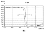
本実施例では、光合成部材5としてダイクロイックミラーを適用している。図2はダイクロイックミラーの入射角45°における分光透過率特性図である。このような特性を有するダイクロイックミラーは、ガラス基板上に誘電体の多層膜を形成することによって製作することができる。このダイクロイックミラーでは、入射角が0°つまりダイクロイックミラーに垂直に光が入射する以外は、必ずその偏光方向によって分光透過率の波長依存特性が異なる。この場合に、図2に示すようにファインダ像を形成する波長400〜600nm台後半の可視域においては90%程度の透過率を有し、可視光の中で赤色成分である600nm台ではS偏光成分は概略660nmで透過率が半値となり、P偏光では概略680nmで透過率が半値となる特性を有している。
【0021】
このような特性を有するダイクロイックミラーを図1に示す光合成部材5としてファインダ光学系に適用し、光源10の発光中心が660〜680nm程度のLEDを用いることによって、図3に示すようなパターンを有した液晶パネル8からの光束はその殆どがダイクロイックミラーにより反射され、接眼レンズ6によって撮影者の瞳孔に導光される。
【0022】
一方、焦点板3上に結像した被写体像からのファインダ光束は90%程度がダイクロイックミラーを透過し、接眼レンズ6によって撮影者の瞳孔に導光される。この際に、ダイクロイックミラーに入射する表示光学系からの光束の偏光方向を液晶パネル8の作用によってS偏光として、表示光束の反射効率を大きくすることにより表示効率を高めることができる。これは完全なS偏光でなくともその目的は達成することができ、このような構成によって赤色の情報表示をファインダ内に自在に行うことができる。
【0023】
図4は光合成部材5に用いる他のダイクロイックミラーの入射角45゜における分光透過率特性図である。このダイクロイックミラーでは、ファインダ像を形成する波長450nm以上の可視域においては90%程度の透過率を有し、可視光の中でS偏光成分は概略450nmで透過率が半値となり、P偏光では概略420nmで透過率が半値となる特性を有している。このような特性を有するダイクロイックミラーをファインダ光学系に適用し、発光中心が450nm程度の光源10を用いることによって表示光学系からの光束はその殆どがダイクロイックミラーにより反射され、青紫色の情報表示をファインダ内に表示し、接眼レンズ6を介して撮影者の瞳孔に導光される。
【0024】
ところで、本実施例では光合成部材5としてダイクロイックミラーを用いているが、参考例として透過特性及び反射特性に波長依存性が殆どないハーフミラーを用いた場合を考えてみる。
【0025】
図5は或るハーフミラーの分光透過特性図である。このハーフミラーは波長400nm〜700nmにおいて、平均透過率が70%程度である。このようなハーフミラーを、図1における光合成部材5として用いた場合に、焦点板3上に結像した被写体像からのファインダ光束の70%程度がハーフミラーを透過し、撮影者の瞳孔に達する。一方、液晶パネル8からの光束の30%程度がハーフミラーで反射され、ファインダ像を重ね合わされて撮影者の瞳孔に達することになる。
【0026】
図5に示すような分光透過特性を持つハーフミラーを光合成部材5として用いた際には、本実施例のようにダイクロイックミラーを光合成部材5として用いた場合と比較して光の利用効率が悪く、ファインダ像と液晶パネル8による情報表示が共に非常に暗いものになってしまう。これに対し、本実施例では光合成部材にダイクロイックミラーを用いているので、焦点板3上に結像した被写体像からのファインダ光束と液晶パネル3からの光束を共に非常に高い効率で観察者に導光することができる。
【0027】
しかしながら後述するように、ダイクロイックミラーは分光透過率特性が光の入射角によって異なるという特性を持っている。図1に示したような系においては、被写体からの光は様々な入射角でダイクロイックミラーに入射するため、上記のようなダイクロイックミラーの特性により観察方向によってファインダ像に色相変化が生じてしまう。
【0028】
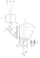
次に、光合成部材5にダイクロイックミラーを用いることによって生ずるファインダの観察方向による色相変化を補正する方法について述べる。図6はファインダ光学系とこの光学系を透過する方向の異なる3つの光束L0、L1、L2を示している。それぞれの光束は撮影レンズ1を透過しクイックリターンミラー2によって反射されて焦点板3上に結像し、ペンタプリズム4、ダイクロイックミラーから成る光合成部材5、検眼レンズ6を経て撮影者の瞳孔に至る。ここで、各光束L0、L1、L2のクイックリターンミラー2への入射角に注目してみる。各光束のクイックリターンミラーへの入射角をθ0 、θ1 、θ2 とすれば、
θ1 <θ0 <θ2
となる。
【0029】
一般に、クイックリターンミラーは撮影レンズ光軸に対して45°に設定されるためθ0 は45°となる。一方、ダイクロイックミラーへの各光束L0、L1、L2の入射角を見てみると、その入射角をそれぞれω0 、ω1 、ω2 とすれば、
ω2 <ω0 <ω1
となる。
【0030】
ファインダ像の上下の観察方向によってダイクロイックミラーへの入射角が変化するため、ダイクロイックミラーへの入射角によらずに、その分光透過率は一定であることが望ましい。しかしながら、本実施例のダイクロイックミラーはガラス基板へ誘電体の多層膜を蒸着することによって、図2、図4で示す分光透過率特性を得ている。このようなダイクロイックミラーでは、分光透過率の角度依存性をなくすことは到底困難であり、ファインダ像が上下方向で色相が変化し好ましくない。
【0031】
具体的に、図2の分光透過率特性を持つダイクロイックミラーを例に挙げて説明すると、ダイクロイックミラーに対する入射角が大きくなると、大←で示すように透過と反射の特性が反転する波長が短波長側にシフトする。逆に、入射角が小さくなると→小で示すように透過と反射の特性が反転する波長が長波長側にシフトする。その結果、このダイクロイックミラーの特性だけで考えれば、ファインダ像の上を見る、つまり図6における光束L1を見ると、ダイクロイックミラーへの入射角が大きく透過可能な長波長側カット波長が短波長側にシフトし赤成分が欠落する結果として、撮影者にはファインダ像が下部よりも青く見える。
【0032】
反対にファインダ像の下を見る、つまり図6における光束L2を見ると、ダイクロイックミラーへの入射角が小さく透過可能な長波長側のカット波長が短波長側にシフトし赤色成分が増加する。結果として、撮影者にはファインダ像が上部よりも赤く見える。
【0033】
このような上下方向の色相変化を防止するため、本実施例ではクイックリターンミラー2を光合成部材5のダイクロイックミラーと類似の特性を持つ誘電体の多層膜による構成として、その反射率の角度依存性による色相の変化が、ダイクロイックミラーによって生ずる色相の変化と相殺するようにしている。
【0034】
一般に、一眼レフレックスカメラに用いるクイックリターンミラーは可視城の波長に対しては概略平坦な反射特性を有するように設定され、その角度依存性も少ない方が望ましいとされている。しかし、本実施例ではクイックリターンミラー2を誘電体の多層膜による構成として、その反射率の入射角度依存性を利用してダイクロイックミラーを含めたファインダ系を通して、色相変化の少ない良好なファインダ系を得ている。
【0035】
なお、本実施例では、誘電体多層膜を施したクイックリターンミラー2を色相変化を防止するための補正手段として用いたが、ダイクロイックミラーによる色相変化を防止するための膜を他の光学部材、例えばペンタプリズムの反射面や透過面、レンズ表面、透明平行平板等に施し、これらの部材を補正手段として用いてもよく、これらの形態は本発明の趣旨を逸脱することはない。
【0036】
しかしながら、クイックリターンミラー2の法線方向に対して、互いの法線方向が直交するように光合成部材5をファインダ系中に配置し、光合成部材5に施されたダイクロイック膜と類似の特性の誘電体多層膜をクイックリターンミラー2に施す本実施例の構成が、本発明の目的を最も容易に実現することができる。
【0037】
【発明の効果】
以上説明したように本発明に係るファインダ系によれば、ファインダ像とそれに重ね合わせて表示される表示情報とが共に明るく、かつ高品位なファインダ像の観察が可能となる。
【図面の簡単な説明】
【図1】本実施例の一眼レフレックスカメラの概略構成図である。
【図2】ダイクロイックミラーの分光透過率特性図である。
【図3】液晶パネルに表示されるパターンの説明図である。
【図4】他のダイクロイックミラーの分光透過率の特性図である。
【図5】参考例のハーフミラーの分光透過率の特性図である。
【図6】観察方向によって異なるダイクロイックミラーへの入射角の説明図である。
【符号の説明】
1 撮影レンズ
2 クイックリターンミラー
3 焦点板
4 ペンタプリズム
5 光合成部材
6 接眼レンズ
7 投影レンズ
8 液晶パネル
9 集光レンズ
10 光源[0001]
BACKGROUND OF THE INVENTION
The present invention relates to a finder system suitable for a single-lens reflex camera that displays various types of shooting information within a finder field of view.
[0002]
[Prior art]
In a conventional single-lens reflex camera or the like of this type, together with an object image formed on the focusing screen by a photographing lens, a photometric range or an autofocusing ranging area arranged at the focusing screen or an optically equivalent position, Various proposals have been made for the in-finder display device of a camera that simultaneously observes the shooting information through the finder optical system.
[0003]
[Problems to be solved by the invention]
For example, as disclosed in Japanese Patent Application Laid-Open No. 55-18664, a relief hologram recorded by converting recorded information due to interference between an object wave and a reference wave into surface irregularities is arranged in the vicinity of the focusing screen, There is known a technique in which a hologram image is reproduced on a focusing screen to display in a finder. However, this relief-type hologram configuration requires advanced technology for production, and is expensive, and it is extremely difficult to form a high-quality hologram image on the focusing screen. ing.
[0004]
In addition, as disclosed in Japanese Patent Application Laid-Open No. 58-181034, a liquid crystal display panel is disposed so as to overlap with a focusing screen, and display in the viewfinder is performed using this liquid crystal display panel.
[0005]
However, with this configuration, the position of the liquid crystal display in the optical axis direction does not exactly coincide with the imaging position on the focusing screen of the photographic lens, and the diopter at the time of finder observation is slightly shifted, and the clear and delicate visual sensation is provided. A liquid crystal member always exists in the required finder optical path of a single-lens reflex camera, and there is a problem that the quality of the finder image is unavoidable and the light quantity cannot be avoided.
[0006]
An object of the present invention is to provide a finder system in which a finder image and display information superimposed on the finder image are both bright and a high-quality finder image can be observed.
[0007]
[Means for Solving the Problems]
In order to achieve the above object, a finder system according to the present invention includes a quick return mirror that reflects light from an objective lens, a focusing screen on which a real image of an object is formed by the objective lens, and the focusing screen. An image reversing member for reversing the real image, an eyepiece for guiding the real image reversed by the image reversing member to an observer, display means for displaying information in a viewfinder field via the eyepiece, and the objective lens And a dichroic mirror that reflects the light from the display means , wherein the quick return mirror is formed with a dielectric multilayer film, and the angle of reflectance of the quick return mirror The angle dependency of the transmittance of the dichroic mirror is corrected by the dependency .
[0008]
An optical apparatus according to the present invention includes the finder system according to the present invention.
[0009]
DETAILED DESCRIPTION OF THE INVENTION
The present invention will be described in detail based on the embodiments shown in the drawings.
FIG. 1 is a schematic configuration diagram of a single-lens reflex camera having a finder optical system according to the present embodiment. A
[0010]
The light flux from the subject is imaged on the focusing
[0011]
At this time, the focal length of the
[0012]
The light beam emitted from the
[0013]
For this reason, in this embodiment, a Fresnel lens is used as the condenser lens 9, thereby realizing a reduction in the size of the apparatus as well as a reduction in the thickness of the lens. Strictly speaking, the imaging relationship between the
[0014]
In any case, an area having the same shape as the information to be superimposed on the finder image is configured to be light transmissive at the time of information display, and can be shielded at other times by the
[0015]
The light beam transmitted through the
[0016]
Further, when the focal length of the
fs / 5 <ft <fs
[0017]
If the focal length ft of the
[0018]
However, if the lower limit of the equation is exceeded, the pattern to be produced on the
[0019]
In the present embodiment, an aspherical lens is used as the
[0020]
In this embodiment, a dichroic mirror is applied as the light combining member 5. FIG. 2 is a spectral transmittance characteristic diagram of the dichroic mirror at an incident angle of 45 °. A dichroic mirror having such characteristics can be manufactured by forming a dielectric multilayer film on a glass substrate. In this dichroic mirror, the wavelength dependence characteristics of the spectral transmittance are always different depending on the polarization direction except that the incident angle is 0 °, that is, light is incident on the dichroic mirror perpendicularly. In this case, as shown in FIG. 2, it has a transmittance of about 90% in the visible region in the latter half of the wavelength range of 400 to 600 nm for forming a finder image, and S-polarized light in the visible light at the 600 nm level, which is a red component. The component has a characteristic that the transmittance is about half value at about 660 nm, and the transmittance is about half value at about 680 nm for P-polarized light.
[0021]
A dichroic mirror having such characteristics is applied to the finder optical system as the light combining member 5 shown in FIG. 1, and an LED having a light emission center of about 660 to 680 nm is used to obtain a pattern as shown in FIG. Most of the light flux from the
[0022]
On the other hand, about 90% of the finder beam from the subject image formed on the focusing
[0023]
FIG. 4 is a spectral transmittance characteristic diagram of another dichroic mirror used for the light combining member 5 at an incident angle of 45 °. This dichroic mirror has a transmittance of about 90% in the visible region of a wavelength of 450 nm or more for forming a finder image, and the transmittance of the S-polarized light component in visible light is approximately 450 nm, and the transmittance is half value. It has a characteristic that the transmittance becomes half value at 420 nm. By applying the dichroic mirror having such characteristics to the finder optical system and using the
[0024]
By the way, although a dichroic mirror is used as the light combining member 5 in this embodiment, a case where a half mirror having almost no wavelength dependency in transmission characteristics and reflection characteristics is used as a reference example.
[0025]
FIG. 5 is a spectral transmission characteristic diagram of a certain half mirror. This half mirror has an average transmittance of about 70% at a wavelength of 400 nm to 700 nm. When such a half mirror is used as the light combining member 5 in FIG. 1, about 70% of the finder beam from the subject image formed on the focusing
[0026]
When a half mirror having a spectral transmission characteristic as shown in FIG. 5 is used as the light combining member 5, the light use efficiency is lower than when the dichroic mirror is used as the light combining member 5 as in this embodiment. Both the finder image and the information display by the
[0027]
However, as will be described later, the dichroic mirror has a characteristic that the spectral transmittance characteristic varies depending on the incident angle of light. In the system as shown in FIG. 1, since light from a subject enters the dichroic mirror at various incident angles, the hue of the finder image changes depending on the viewing direction due to the characteristics of the dichroic mirror as described above.
[0028]
Next, a method for correcting the hue change caused by the finder viewing direction caused by using a dichroic mirror for the light combining member 5 will be described. FIG. 6 shows the finder optical system and three light beams L0, L1, and L2 having different directions of transmission through the optical system. Each light beam passes through the
θ1 <θ0 <θ2
It becomes.
[0029]
In general, since the quick return mirror is set to 45 ° with respect to the optical axis of the photographing lens, θ0 is 45 °. On the other hand, looking at the incident angles of the light beams L0, L1, and L2 on the dichroic mirror, if the incident angles are ω0, ω1, and ω2, respectively,
ω2 <ω0 <ω1
It becomes.
[0030]
Since the incident angle to the dichroic mirror varies depending on the upper and lower observation directions of the finder image, it is desirable that the spectral transmittance is constant regardless of the incident angle to the dichroic mirror. However, the dichroic mirror of this embodiment obtains the spectral transmittance characteristics shown in FIGS. 2 and 4 by depositing a dielectric multilayer film on a glass substrate. In such a dichroic mirror, it is very difficult to eliminate the angle dependency of the spectral transmittance, and the hue of the finder image changes in the vertical direction, which is not preferable.
[0031]
Specifically, the dichroic mirror having the spectral transmittance characteristics shown in FIG. 2 will be described as an example. When the incident angle with respect to the dichroic mirror increases, the wavelength at which the transmission and reflection characteristics are inverted is short as shown by large ←. Shift to the side. Conversely, when the incident angle is decreased, the wavelength at which the transmission and reflection characteristics are inverted shifts to the longer wavelength side, as indicated by → small. As a result, considering only the characteristics of the dichroic mirror, when looking at the top of the finder image, that is, when viewing the light beam L1 in FIG. 6, the long wavelength side cut wavelength that allows transmission with a large incident angle to the dichroic mirror is short wavelength side. As a result, the viewfinder image appears blue to the photographer.
[0032]
Conversely, when looking under the viewfinder image, that is, when viewing the light beam L2 in FIG. 6, the cut wavelength on the long wavelength side where the incident angle to the dichroic mirror is small and transmitted is shifted to the short wavelength side, and the red component increases. As a result, the viewfinder image appears red to the photographer from the top.
[0033]
In order to prevent such a change in the hue in the vertical direction, in this embodiment, the
[0034]
In general, a quick return mirror used in a single-lens reflex camera is set to have a substantially flat reflection characteristic with respect to the wavelength of a visible castle, and it is desirable that the angle dependency thereof is small. However, in this embodiment, the
[0035]
In this embodiment, the
[0036]
However, the photosynthetic member 5 is arranged in the finder system so that the normal directions of the
[0037]
【The invention's effect】
As described above, according to the finder system according to the present invention, both the finder image and the display information displayed superimposed thereon can be bright and a high-quality finder image can be observed.
[Brief description of the drawings]
FIG. 1 is a schematic configuration diagram of a single-lens reflex camera according to an embodiment of the present invention.
FIG. 2 is a spectral transmittance characteristic diagram of a dichroic mirror.
FIG. 3 is an explanatory diagram of patterns displayed on a liquid crystal panel.
FIG. 4 is a characteristic diagram of spectral transmittance of another dichroic mirror.
FIG. 5 is a characteristic diagram of spectral transmittance of a half mirror of a reference example.
FIG. 6 is an explanatory diagram of an incident angle to a dichroic mirror that varies depending on an observation direction.
[Explanation of symbols]
DESCRIPTION OF
Claims (3)
Priority Applications (2)
| Application Number | Priority Date | Filing Date | Title |
|---|---|---|---|
| JP34447797A JP4124847B2 (en) | 1996-12-10 | 1997-11-28 | Viewfinder system and optical apparatus having the viewfinder system |
| US08/986,954 US5893650A (en) | 1996-12-10 | 1997-12-08 | Viewfinder system and single-lens reflex camera having the same |
Applications Claiming Priority (3)
| Application Number | Priority Date | Filing Date | Title |
|---|---|---|---|
| JP8-346768 | 1996-12-10 | ||
| JP34676896 | 1996-12-10 | ||
| JP34447797A JP4124847B2 (en) | 1996-12-10 | 1997-11-28 | Viewfinder system and optical apparatus having the viewfinder system |
Publications (2)
| Publication Number | Publication Date |
|---|---|
| JPH10228057A JPH10228057A (en) | 1998-08-25 |
| JP4124847B2 true JP4124847B2 (en) | 2008-07-23 |
Family
ID=26577779
Family Applications (1)
| Application Number | Title | Priority Date | Filing Date |
|---|---|---|---|
| JP34447797A Expired - Fee Related JP4124847B2 (en) | 1996-12-10 | 1997-11-28 | Viewfinder system and optical apparatus having the viewfinder system |
Country Status (1)
| Country | Link |
|---|---|
| JP (1) | JP4124847B2 (en) |
Families Citing this family (4)
| Publication number | Priority date | Publication date | Assignee | Title |
|---|---|---|---|---|
| JP2004258232A (en) * | 2003-02-25 | 2004-09-16 | Nikon Corp | Display optical system and finder optical system |
| JP4974780B2 (en) | 2007-06-22 | 2012-07-11 | キヤノン株式会社 | Optical observation apparatus and imaging apparatus |
| JP5664196B2 (en) * | 2010-12-13 | 2015-02-04 | 株式会社ニコン | Erecting member and optical device |
| WO2018164058A1 (en) * | 2017-03-09 | 2018-09-13 | 株式会社ニコン | Optical device |
-
1997
- 1997-11-28 JP JP34447797A patent/JP4124847B2/en not_active Expired - Fee Related
Also Published As
| Publication number | Publication date |
|---|---|
| JPH10228057A (en) | 1998-08-25 |
Similar Documents
| Publication | Publication Date | Title |
|---|---|---|
| JP3450576B2 (en) | Display device in viewfinder | |
| US5893650A (en) | Viewfinder system and single-lens reflex camera having the same | |
| JP4124847B2 (en) | Viewfinder system and optical apparatus having the viewfinder system | |
| JPH0743781A (en) | Finder device for camera | |
| JPS6145212B2 (en) | ||
| TWI521242B (en) | An optical filter element that corrects spectral aberration | |
| JP3774528B2 (en) | SLR camera viewfinder | |
| US6047139A (en) | Camera capable of display in finder | |
| US6914726B2 (en) | Optical apparatus and viewing optical system thereof which is capable of displaying information | |
| JP2004109865A (en) | Finder device and optical instrument equipped with same | |
| JP4154022B2 (en) | Viewfinder system and optical equipment using the same | |
| JP3445052B2 (en) | Display device in viewfinder | |
| JP2007264029A (en) | Finder optical system and optical equipment mounted with same | |
| JP2012068310A (en) | Observation optical system and optical equipment | |
| JPH06301097A (en) | Camera having focus aid indication | |
| JPH09236858A (en) | In-finder display device | |
| JP2008033104A (en) | Finder device and imaging apparatus having the same | |
| JP2000089336A (en) | Display device within finder picture plane | |
| JPH09236859A (en) | In-finder display device | |
| JP2006171658A (en) | Finder optical system and imaging apparatus having same | |
| JPH06301098A (en) | Camera having focus aid indication | |
| JP3243020B2 (en) | Optical viewfinder | |
| JP3332988B2 (en) | Camera with real image finder | |
| JP3147473B2 (en) | Arvada reverse Galileo finder | |
| JPH07319032A (en) | Device for displaying information within viewfinder |
Legal Events
| Date | Code | Title | Description |
|---|---|---|---|
| A521 | Written amendment |
Free format text: JAPANESE INTERMEDIATE CODE: A523 Effective date: 20040318 |
|
| A621 | Written request for application examination |
Free format text: JAPANESE INTERMEDIATE CODE: A621 Effective date: 20040318 |
|
| A977 | Report on retrieval |
Free format text: JAPANESE INTERMEDIATE CODE: A971007 Effective date: 20060831 |
|
| A131 | Notification of reasons for refusal |
Free format text: JAPANESE INTERMEDIATE CODE: A131 Effective date: 20070522 |
|
| A521 | Written amendment |
Free format text: JAPANESE INTERMEDIATE CODE: A523 Effective date: 20070720 |
|
| TRDD | Decision of grant or rejection written | ||
| A01 | Written decision to grant a patent or to grant a registration (utility model) |
Free format text: JAPANESE INTERMEDIATE CODE: A01 Effective date: 20080430 |
|
| A01 | Written decision to grant a patent or to grant a registration (utility model) |
Free format text: JAPANESE INTERMEDIATE CODE: A01 |
|
| A61 | First payment of annual fees (during grant procedure) |
Free format text: JAPANESE INTERMEDIATE CODE: A61 Effective date: 20080507 |
|
| R150 | Certificate of patent or registration of utility model |
Free format text: JAPANESE INTERMEDIATE CODE: R150 |
|
| FPAY | Renewal fee payment (event date is renewal date of database) |
Free format text: PAYMENT UNTIL: 20110516 Year of fee payment: 3 |
|
| FPAY | Renewal fee payment (event date is renewal date of database) |
Free format text: PAYMENT UNTIL: 20120516 Year of fee payment: 4 |
|
| FPAY | Renewal fee payment (event date is renewal date of database) |
Free format text: PAYMENT UNTIL: 20120516 Year of fee payment: 4 |
|
| FPAY | Renewal fee payment (event date is renewal date of database) |
Free format text: PAYMENT UNTIL: 20130516 Year of fee payment: 5 |
|
| FPAY | Renewal fee payment (event date is renewal date of database) |
Free format text: PAYMENT UNTIL: 20140516 Year of fee payment: 6 |
|
| LAPS | Cancellation because of no payment of annual fees |