JP4124490B2 - Device for detection of inhomogeneities in liquid flow - Google Patents
Device for detection of inhomogeneities in liquid flow Download PDFInfo
- Publication number
- JP4124490B2 JP4124490B2 JP53951298A JP53951298A JP4124490B2 JP 4124490 B2 JP4124490 B2 JP 4124490B2 JP 53951298 A JP53951298 A JP 53951298A JP 53951298 A JP53951298 A JP 53951298A JP 4124490 B2 JP4124490 B2 JP 4124490B2
- Authority
- JP
- Japan
- Prior art keywords
- liquid passage
- liquid
- housing
- receiver
- wave propagation
- Prior art date
- Legal status (The legal status is an assumption and is not a legal conclusion. Google has not performed a legal analysis and makes no representation as to the accuracy of the status listed.)
- Expired - Fee Related
Links
Images


Classifications
-
- G—PHYSICS
- G01—MEASURING; TESTING
- G01N—INVESTIGATING OR ANALYSING MATERIALS BY DETERMINING THEIR CHEMICAL OR PHYSICAL PROPERTIES
- G01N29/00—Investigating or analysing materials by the use of ultrasonic, sonic or infrasonic waves; Visualisation of the interior of objects by transmitting ultrasonic or sonic waves through the object
- G01N29/02—Analysing fluids
- G01N29/032—Analysing fluids by measuring attenuation of acoustic waves
-
- G—PHYSICS
- G01—MEASURING; TESTING
- G01N—INVESTIGATING OR ANALYSING MATERIALS BY DETERMINING THEIR CHEMICAL OR PHYSICAL PROPERTIES
- G01N2291/00—Indexing codes associated with group G01N29/00
- G01N2291/02—Indexing codes associated with the analysed material
- G01N2291/024—Mixtures
- G01N2291/02433—Gases in liquids, e.g. bubbles, foams
-
- G—PHYSICS
- G01—MEASURING; TESTING
- G01N—INVESTIGATING OR ANALYSING MATERIALS BY DETERMINING THEIR CHEMICAL OR PHYSICAL PROPERTIES
- G01N2291/00—Indexing codes associated with group G01N29/00
- G01N2291/02—Indexing codes associated with the analysed material
- G01N2291/028—Material parameters
- G01N2291/02836—Flow rate, liquid level
Abstract
Description
【技術分野】
本発明は、液流中の不均質性、特に気泡を、超音波によって検出する装置に関する。
【背景技術】
多くの状況下で、液流中の気泡のような不均質性の存在を検出できることが重要である。例えば、医療分野では、治療液を非経口投与する際に患者に気泡が注入されないようにしなければならない。産業分野では、例えば、冷却システムに気泡が存在すると、冷却能が不充分となる。分析分野では、特に、液体クロマトグラフィーの過程での気泡の検出が挙げられる。
液流中の気泡の一般的検出法は超音波を用いるものであり、気体の音響インピーダンスが液体又は固体よりも相対的に高いことに依拠する。従って、液体導管の片側の送信器から導管の逆側の受信器に向けて超音波を発振した場合、例えば、液体中に気泡が存在すると、導管内に液体しか存在しない場合に比べて受信器の音響エネルギーの明らかな減少として検出することができる。
超音波は、電圧で付勢すると結晶が振動する圧電トランスデューサー(いわゆるピエゾトランスデューサー)で発生させることができる。逆に、こうした結晶に超音波が当たると、結晶は電圧を生じる。従って、超音波トランスデューサーは音波を送信し、受信することができる。
液体クロマトグラフィー用の気泡検出装置は既に公知であり、かかる装置はクロマトグラフィーシステムに接続でき、液体通路を有するプラスチックブロックを備えていて、液体通路の両側に送信器と受信器が備え付けられている。この装置の欠点は、送信された超音波が液体通路から外れて伝搬することがあり、それでも受信器に達するので、液体と空気から得られる信号の差がさほど大きくないことである。同様に、液体通路を通過した超音波が受信器から外れて伝搬することもある。そのため、装置には、超音波トランスデューサーからの信号を処理するための複雑な電子機器だけでなく、装置にインストールしたときに複雑なトリミング法を必要とする。
米国特許第4,418,565号には、プラスチックブロックに一対の向かい合った超音波トランスデューサー(送信器及び受信器)が挿入された形態の超音波気泡検出装置であって、トランスデューサー間に溝が画成され、その溝に、気泡を検出すべき液体導管、典型的には液体の非経口投与用の袋又はビンからのチューブが装着される超音波気泡検出装置が記載されている。各トランスデューサーと通路の間に、超音波伝達性エラストマー材料が充填された凹部が存在する。エラストマー材料を通過し、従って液体導管を通過する経路以外の送信器から受信器への超音波の伝搬を防止するため、空気含有スロットが溝の底に配置される。このスロットは、液体導管を収容するには狭すぎ、少なくとも超音波トランスデューサーの下縁より下まで延びる。
遮蔽により超音波を導くこの構造は、最初に述べた気泡検出装置の検出の問題を少なくとも部分的に解決するが、この構造は別の問題を有する。まず第一に、装置自体が複雑な構造であり、特にネジ、スペーサーエレメント及び加圧プレートを含む。更に、チューブの検出は非実際的であり、チューブが良好な音響結合で装着されていることが必要とされる。これはチューブが可撓性であれば実際に達成できるが、このようなチューブでは例えば液体クロマトグラフィーで一般的な比較的高い流体圧に耐えることができない。一方、剛性チューブで十分な音響結合を達成するには、装着用ペーストの使用が必要とされるが、これは非常に非実用的である。液体導管溝の下に画性されたスロットのため、気泡検出装置の強度特性、特にひねり又はねじれ強度に関して悪くなる。
【発明の開示】
【発明が解決しようとする課題】
本発明の一つの目的は、液流中の気泡及び他の不均質性の検出のための超音波装置であって、最初に述べた装置のように、一体耐圧性液体通路を有しているが、気体の信号と液体の信号との大きな差を保証するために該液体通路が音波経路の支配的要素である装置を提供することである。
本発明の他の目的は、駆動用及び信号処理用の簡単な電子機器を使用できる装置を提供することである。
本発明の更に別の目的は、丈夫で、使い易い上述のタイプの装置を提供することである。
本発明の更なる目的は、あまり精巧でなく、製造し易い上述のタイプの装置を提供することである。
【課題を解決するための手段】
本発明によれば、これらの及び他の目的及び利点は、液体通路を備える一体構造ハウジングと該通路の両側でハウジングに装着された2つの対向する超音波トランスデューサーとを有する超音波気泡検出装置に、各トランスデューサーと液体通路との間にかつ音波伝搬路の両側にハウジングに切り込まれた凹部を設けることによって、凹部が共にトランスデューサー間の音波路を遮断して、受信器で受信される実質的にすべての超音波エネルギーが液体通路を通過するようにすることによって達成される。換言すれば、音波の横断方向における通路と周囲の物質との間の音波分布を、超音波がハウジングを通して伝播するときに通過する断面積の大部分を上記通路が占めるようにする。こうして、気体信号と液体信号との大きくて信頼性の高い差が得られる。凹部の向かい合った配置によって、ハウジングの優れた強度も維持できる。
従って、本発明の一つの態様は、液流中の不均質性を検出する装置であって、当該装置が、超音波透過性の材料からなる一体構造ハウジングと、ハウジングを貫通する液体通路と、液体通路を液流に接続するためのハウジングの入口及び出口と、ハウジングの液体通路の両側に、一方が送信器として、他方が受信器として設けられた超音波トランスデューサーとを備えていて、上記液体通路が送信器と受信器の間の音波伝搬路に位置していて、上記受信器で受信された超音波に基づいて液流中の不均質性を検出することができる、装置に関する。この装置は、ハウジングが液体通路の受信器側と受信器側とに2つの向かい合った凹部を有していることを特徴とする。音波伝搬路及び液体通路に垂直な方向において、この2つの凹部は、音波伝搬路の両側で実質的に液体通路の各外縁のレベルまで延在していて、一緒に、送信トランスデューサーと受信トランスデューサーの間に音波伝搬を導いて超音波伝搬が実質的に液体通路を通して(そして周囲の物質を通らずに)起こるようにする。
他の態様では、本発明は、上述の装置に加えて、超音波トランスデューサー殻の信号を処理し提示するための手段を備える、液流中の不均質性の検出用システムに関する。
以下、本発明の理解を容易にするために、添付の図面を参照しながら、もっぱら例示を目的とした具体的な実施形態に関して詳しく説明する。
【発明を実施するための最良の形態】
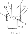
図1〜図3に示す気泡検出装置は、液体クロマトグラフィー用の通路中の空気/液体の検出に主に用いるためのものであるが、もちろん、液流中の気泡(又は他の不均質性)を検出すべき他の用途にも使用できる。本装置は、問題とする液流系と接続されるように設計された入口及び出口2a,2bを有する液体通路2を備えたハウジング又はセルボディー1を含む(図3)。セルボディー1は、適当には硬質プラスチック、例えばPEEKから成る。通路の幅(断面直径)は、想定される液体クロマトグラフィー用途のためであり、典型的には1〜5mmの範囲である。2つの超音波トランスデューサー3,4(ここでは、圧電性結晶のディスク、いわゆるピエゾトランスデューサーである。)は、各々、液体通路2の両側でセルボディーに装着されている。以下でさらに詳しく説明するが、一方のトランスデューサーは送信器として使用され、他方は受信器として電子制御回路と協同して使用される。最高の性能のため、圧電トランスデューサーは、その共鳴周波数で使用されるが、共鳴周波数は特に結晶ディスクの厚さに依存する。例えば、直径5mm及び厚さ0.5mmの2枚のディスクの組合せでは、共鳴は約4MHzである。
図3に示す実施形態では、2つのトランスデューサー3,4は、トランスデューサーと液体通路との距離を短くするため、セルボディーのくびれ部5に装着される。
セルボディー1は、更に、2つの向かい合った切込み部又は凹部6,7を備えており、一方の凹部は一方のトランスデューサー3と液体通路2との間に、他方の凹部は他方のトランスデューサー4と液体通路2との間に設けられる。図1及び2で、凹部6,7は反対方向に垂直に通路2の各外縁まで延在しており、これらの外縁を図1では点線8a,8bで示す。これらの2つの垂直及び水平方向に向かい合った凹部6,7は、共に、送信トランスデューサーから発振される音波の遮蔽又は「絞り」として機能し、トランスデューサー3,4間を伝搬する音波が辿る経路は、図1及び図2の垂直方向には、基本的に液体通路の幅に限定される。得られる音波経路を図2に符号9で示す。容易に判別できるように、この超音波の遮蔽又は誘導装置は、受信トランスデューサーで検出される実質的にすべての音響エネルギーが、液体通路2を通るようにする。音波誘導又は遮蔽の観点から、もちろん、図1及び図2の凹部6,7が水平方向に、図1及び図2に示すように、本質的に各トランスデューサー3,4から通路2までの全域に延在していると有利である。
2つの凹部6,7は、図1及び図2で垂直に見たときに、液体通路2の異なる側に位置しているため、セルボディーは相当なひねり又はねじれ強度を有する。通路2の周囲の材料の厚さ、及び特に図3の実施形態のくびれ部5は、もちろん、各々の具体的用途に対する機械的条件に応じて調整される。所望により、凹部6,7は高い音響インピーダンスを有する物質で満たしてもよい。
上記で強調したように、液体通路2が、発振された超音波がセルを通る面積の大部分を占めることから、液体と気体(通常は空気)とで検出されるそれぞれの音波強度に大きな信頼性の高い差が得られる。これは、ひいては、検出器セルの駆動に必要な電子回路を非常に小さく作ることができるという結果をもたらす。このような回路の模式的例を図4に示す。
この回路では、ここでは符号10で示す上述のタイプの検出器セルの送信トランスデューサーを増幅器11の入力側に接続し、検出器セル10の受信器を抵抗器12を介して増幅器11の出力側に接続する。増幅器出力は、また整流器及びトランジスターを含む出力駆動段13に接続する。抵抗器12の大きさは、増幅セル検出器信号が所望のレベルとなるように調整される。駆動段13からの出力信号を、次いで、適当なディスプレー装置に導くか、或いは自動システムのコントロール信号として使用する。
以上から明らかなように、上述の気泡検出装置は、小さな液体通路寸法に適した丈夫な装置をもたらし、信頼性の高い気泡検出を与え、簡単な制御電子回路しか必要とせず、併せて取扱い及び製造(一体構造のセルボディー)が容易である。
本発明は、もちろん、上記で具体的に記載した実施形態に限定されず、特許請求の範囲に記載された発明の概念の範囲内で多くの方法で変更及び修正できる。
【図面の簡単な説明】
【図1】図1は、本発明の装置の実施形態の模式的断面図である。
【図2】図2は、図1と同様の図であるが、音波経路を示したものである。
【図3】図3は、本発明の装置の実施形態の模式的透視図であり、実質的に図1及び2に示す実施形態に対応する。
【図4】図4は、本発明の装置からのトランスデューサー信号の電子的処理の模式的回路図である。【Technical field】
The present invention relates to an apparatus for detecting inhomogeneities in a liquid flow, particularly bubbles, by ultrasonic waves.
[Background]
Under many circumstances, it is important to be able to detect the presence of inhomogeneities such as bubbles in the liquid stream. For example, in the medical field, it is necessary to prevent bubbles from being injected into a patient when a therapeutic solution is administered parenterally. In the industrial field, for example, if air bubbles are present in the cooling system, the cooling capacity is insufficient. In the analytical field, in particular, the detection of bubbles in the process of liquid chromatography is mentioned.
A common method for detecting bubbles in a liquid flow uses ultrasound and relies on the relative acoustic impedance of a gas being higher than that of a liquid or solid. Therefore, when ultrasonic waves are oscillated from the transmitter on one side of the liquid conduit toward the receiver on the opposite side of the conduit, for example, when bubbles are present in the liquid, the receiver is compared with the case where only liquid is present in the conduit. It can be detected as a clear decrease in acoustic energy.
The ultrasonic wave can be generated by a piezoelectric transducer (a so-called piezo transducer) that vibrates when a voltage is applied. Conversely, when an ultrasonic wave hits such a crystal, the crystal generates a voltage. Accordingly, the ultrasonic transducer can transmit and receive sound waves.
Bubble detection devices for liquid chromatography are already known, such devices can be connected to a chromatography system, have a plastic block with a liquid passage, with transmitter and receiver on both sides of the liquid passage. . The disadvantage of this device is that the transmitted ultrasonic waves may propagate out of the liquid path and still reach the receiver, so that the difference between the signals obtained from the liquid and air is not so great. Similarly, ultrasonic waves that have passed through the liquid passage may propagate away from the receiver. Therefore, the apparatus requires not only complicated electronic equipment for processing signals from the ultrasonic transducer, but also a complicated trimming method when installed in the apparatus.
U.S. Pat. No. 4,418,565 discloses an ultrasonic bubble detection device in which a pair of opposing ultrasonic transducers (transmitter and receiver) are inserted into a plastic block, and a groove is formed between the transducers. And an ultrasonic bubble detection device is described in which a groove is fitted with a liquid conduit in which bubbles are to be detected, typically a bag or bottle for parenteral administration of liquid. Between each transducer and passage there is a recess filled with an ultrasonically transmissive elastomeric material. An air-containing slot is disposed at the bottom of the groove to prevent propagation of ultrasonic waves from the transmitter to the receiver other than the path through the elastomeric material and thus through the liquid conduit. This slot is too narrow to accommodate the liquid conduit and extends at least below the lower edge of the ultrasonic transducer.
While this structure, which guides the ultrasonic waves by shielding, at least partially solves the detection problem of the bubble detector described at the outset, this structure has another problem. First of all, the device itself is a complex structure, especially including screws, spacer elements and pressure plates. Furthermore, tube detection is impractical and requires that the tube be mounted with good acoustic coupling. This can be achieved in practice if the tube is flexible, but such a tube cannot withstand the relatively high fluid pressures common in, for example, liquid chromatography. On the other hand, to achieve sufficient acoustic coupling with a rigid tube requires the use of a mounting paste, which is very impractical. Due to the well-defined slot under the liquid conduit groove, the strength characteristics of the bubble detection device, particularly the twist or twist strength, are worse.
DISCLOSURE OF THE INVENTION
[Problems to be solved by the invention]
One object of the present invention is an ultrasonic device for the detection of bubbles and other inhomogeneities in a liquid flow, which has an integrated pressure-resistant liquid passage as in the first described device. Is to provide a device in which the liquid path is the dominant element of the acoustic wave path to ensure a large difference between the gas signal and the liquid signal.
Another object of the present invention is to provide an apparatus that can use simple electronic devices for driving and signal processing.
Yet another object of the present invention is to provide a device of the type described above that is sturdy and easy to use.
It is a further object of the present invention to provide a device of the type described above that is less elaborate and easy to manufacture.
[Means for Solving the Problems]
In accordance with the present invention, these and other objects and advantages include an ultrasonic bubble detection device having a monolithic housing with a liquid passage and two opposing ultrasonic transducers mounted on the housing on opposite sides of the passage. In addition, by providing recesses cut into the housing between each transducer and the liquid passage and on both sides of the sound wave propagation path, both the recesses block the sound wave path between the transducers and are received by the receiver. This is accomplished by allowing substantially all of the ultrasonic energy to pass through the liquid passage. In other words, the sound wave distribution between the passage in the transverse direction of the sound wave and the surrounding material causes the passage to occupy most of the cross-sectional area through which the ultrasonic wave passes through the housing. Thus, a large and reliable difference between the gas signal and the liquid signal is obtained. The excellent strength of the housing can also be maintained by the opposing arrangement of the recesses.
Accordingly, one aspect of the present invention is an apparatus for detecting inhomogeneities in a liquid flow, the apparatus comprising an integral housing made of an ultrasonically permeable material, a liquid passage extending through the housing, An inlet and an outlet of the housing for connecting the liquid passage to the liquid flow; and an ultrasonic transducer provided on both sides of the liquid passage of the housing, one as a transmitter and the other as a receiver, The present invention relates to an apparatus in which a liquid passage is located in a sound wave propagation path between a transmitter and a receiver, and inhomogeneity in a liquid flow can be detected based on ultrasonic waves received by the receiver. This device is characterized in that the housing has two opposing recesses on the receiver side and the receiver side of the liquid passage. In the direction perpendicular to the acoustic wave propagation path and the liquid passage, the two recesses extend substantially on both sides of the acoustic wave propagation path to the level of each outer edge of the liquid passage, and together, the transmitting transducer and the receiving transformer. Sound propagation is conducted between the reducers so that the ultrasonic propagation occurs substantially through the liquid passage (and not through the surrounding material).
In another aspect, the invention relates to a system for the detection of inhomogeneities in a liquid stream comprising means for processing and presenting signals of ultrasonic transducer shells in addition to the apparatus described above.
Hereinafter, in order to facilitate the understanding of the present invention, specific embodiments for the purpose of illustration will be described in detail with reference to the accompanying drawings.
BEST MODE FOR CARRYING OUT THE INVENTION
The bubble detection device shown in FIGS. 1-3 is primarily intended for the detection of air / liquid in passages for liquid chromatography, but of course bubbles (or other inhomogeneities in the liquid flow) ) Can also be used for other applications that should be detected. The device comprises a housing or
In the embodiment shown in FIG. 3, the two
The
Since the two
As emphasized above, since the
In this circuit, the transmitting transducer of the above-mentioned type of detector cell, indicated here by
As is apparent from the foregoing, the bubble detection device described above provides a robust device suitable for small liquid passage dimensions, provides reliable bubble detection, requires only simple control electronics, and is both handled and Manufacture (one-piece cell body) is easy.
The invention is of course not limited to the embodiments specifically described above, but can be varied and modified in many ways within the scope of the inventive concept described in the claims.
[Brief description of the drawings]
FIG. 1 is a schematic cross-sectional view of an embodiment of the apparatus of the present invention.
FIG. 2 is a view similar to FIG. 1, but showing a sound wave path.
FIG. 3 is a schematic perspective view of an embodiment of the apparatus of the present invention, substantially corresponding to the embodiment shown in FIGS.
FIG. 4 is a schematic circuit diagram of electronic processing of transducer signals from the apparatus of the present invention.
Claims (7)
超音波透過性の材料からなる一体構造ハウジング(1)、
ハウジング(1)を貫通する液体通路(2)、
液体通路(2)を液流に接続するためのハウジング(1)の入口及び出口(2a,2b)、及び
上記ハウジングの液体通路(2)の両側に、一方が送信器として、他方が受信器として設けられた超音波トランスデューサー手段(3,4)であって、液体通路(2)が上記送信器と受信器の間の音波伝搬路に位置していて、上記受信器で受信された送信超音波に基づいて液流中の不均質性を検出することができる、超音波トランスデューサー手段(3,4)
を備えており、
ハウジング(1)が液体通路(2)の送信器側と受信器側とに2つの向かい合った凹部(6,7)を有していて、該凹部が音波伝搬路(9)及び液体通路(2)に垂直な方向において音波伝搬路の両側で実質的に液体通路(2)の各外縁(8a,8b)まで延在しているとともに、音波伝搬方向において各々一方の超音波トランスデューサー手段(3,4)から液体通路(2)の近傍まで延在しているが、凹部と他方の超音波トランスデューサー手段との間の残りのハウジング部分には凹部が設けられておらず、凹部(6,7)が一緒に遮蔽によって送信器と受信器の間に音波伝搬を導いて超音波伝搬が実質的に液体通路(2)を通して起こることを特徴とする装置。A device for detecting inhomogeneities in a liquid flow, the device comprising:
Monolithic housing (1) made of ultrasonically transparent material,
A liquid passage (2) passing through the housing (1),
On the both sides of the inlet and outlet (2a, 2b) of the housing (1) for connecting the liquid passage (2) to the liquid flow and the liquid passage (2) of the housing, one is a transmitter and the other is a receiver The ultrasonic transducer means (3, 4) provided as: the liquid passage (2) is located in the sound wave propagation path between the transmitter and receiver, and the transmission received by the receiver Ultrasonic transducer means (3, 4) capable of detecting inhomogeneities in a liquid flow based on ultrasonic waves
With
The housing (1) has two opposing recesses (6, 7) on the transmitter side and the receiver side of the liquid passage (2), which recesses are the sound wave propagation path (9) and the liquid passage (2 ) Substantially extend to both outer edges (8a, 8b) of the liquid passage (2) on both sides of the sound wave propagation path in the direction perpendicular to the sound wave propagation path, and one ultrasonic transducer means (3 in the sound wave propagation direction). , 4) to the vicinity of the liquid passage (2), but the remaining housing portion between the recess and the other ultrasonic transducer means is not provided with a recess, and the recess (6, 7) A device characterized in that the ultrasonic wave propagation occurs substantially through the liquid passage (2), with 7) together guiding acoustic wave propagation between the transmitter and the receiver by shielding.
Applications Claiming Priority (3)
| Application Number | Priority Date | Filing Date | Title |
|---|---|---|---|
| SE9700853-6 | 1997-03-10 | ||
| SE9700853A SE9700853D0 (en) | 1997-03-10 | 1997-03-10 | Device for detecting inhomogeneities in a fluid flow |
| PCT/SE1998/000419 WO1998040733A1 (en) | 1997-03-10 | 1998-03-10 | Apparatus for detection of inhomogeneities in a liquid flow |
Publications (2)
| Publication Number | Publication Date |
|---|---|
| JP2001514754A JP2001514754A (en) | 2001-09-11 |
| JP4124490B2 true JP4124490B2 (en) | 2008-07-23 |
Family
ID=20406090
Family Applications (1)
| Application Number | Title | Priority Date | Filing Date |
|---|---|---|---|
| JP53951298A Expired - Fee Related JP4124490B2 (en) | 1997-03-10 | 1998-03-10 | Device for detection of inhomogeneities in liquid flow |
Country Status (8)
| Country | Link |
|---|---|
| US (1) | US6282949B1 (en) |
| EP (1) | EP0966677B1 (en) |
| JP (1) | JP4124490B2 (en) |
| AT (1) | ATE423307T1 (en) |
| DE (1) | DE69840569D1 (en) |
| ES (1) | ES2320821T3 (en) |
| SE (1) | SE9700853D0 (en) |
| WO (1) | WO1998040733A1 (en) |
Families Citing this family (13)
| Publication number | Priority date | Publication date | Assignee | Title |
|---|---|---|---|---|
| GB9921982D0 (en) * | 1999-09-16 | 1999-11-17 | Secretary Trade Ind Brit | Cavitation sensor |
| JP2004503324A (en) * | 2000-07-13 | 2004-02-05 | トランサージカル,インコーポレイテッド | Energy imparting device with expandable annular lens |
| US6635054B2 (en) * | 2000-07-13 | 2003-10-21 | Transurgical, Inc. | Thermal treatment methods and apparatus with focused energy application |
| US6763722B2 (en) * | 2001-07-13 | 2004-07-20 | Transurgical, Inc. | Ultrasonic transducers |
| US20040082859A1 (en) | 2002-07-01 | 2004-04-29 | Alan Schaer | Method and apparatus employing ultrasound energy to treat body sphincters |
| EP1596746B1 (en) | 2003-02-20 | 2016-10-19 | ReCor Medical, Inc. | Ultrasonic ablation devices |
| EP1486827B1 (en) * | 2003-06-11 | 2011-11-02 | ASML Netherlands B.V. | Lithographic apparatus and device manufacturing method |
| US10499937B2 (en) | 2006-05-19 | 2019-12-10 | Recor Medical, Inc. | Ablation device with optimized input power profile and method of using the same |
| US7805978B2 (en) * | 2006-10-24 | 2010-10-05 | Zevex, Inc. | Method for making and using an air bubble detector |
| JP5643642B2 (en) * | 2007-07-25 | 2014-12-17 | ジーイー・ヘルスケア・バイオ−サイエンシズ・アーベー | Separation matrix |
| EP2376011B1 (en) | 2009-01-09 | 2019-07-03 | ReCor Medical, Inc. | Apparatus for treatment of mitral valve insufficiency |
| US9518958B2 (en) * | 2012-12-18 | 2016-12-13 | Deka Products Limited Partnership | System, method, and apparatus for detecting air in a fluid line using active rectification |
| EP2372330B1 (en) * | 2010-03-31 | 2013-01-16 | LIFEBRIDGE Medizintechnik AG | Air bubble sensor |
Family Cites Families (9)
| Publication number | Priority date | Publication date | Assignee | Title |
|---|---|---|---|---|
| GB1418181A (en) * | 1973-02-27 | 1975-12-17 | Cole E M | Ultrasonic detection of inclusions in a fluid flowing within a tube |
| US3974681A (en) * | 1973-10-23 | 1976-08-17 | Jerry Namery | Ultrasonic bubble detector |
| US4015464A (en) * | 1975-02-21 | 1977-04-05 | The Washington University | Ultrasonic continuous wave particle monitor |
| US4418565A (en) * | 1980-12-03 | 1983-12-06 | Baxter Travenol Laboratories, Inc. | Ultrasonic bubble detector |
| JPS58131555A (en) * | 1982-01-29 | 1983-08-05 | Aisin Warner Ltd | Detection of characteristic of liquid by sound wave |
| US4607520A (en) * | 1984-01-09 | 1986-08-26 | Introtek Corporation | Method and apparatus for detecting discontinuities in a fluid stream |
| US4651555A (en) * | 1984-09-11 | 1987-03-24 | Introtek Corporation | Apparatus for detecting discontinuities in a fluid stream |
| US5394732A (en) * | 1993-09-10 | 1995-03-07 | Cobe Laboratories, Inc. | Method and apparatus for ultrasonic detection of air bubbles |
| DE4435594C2 (en) * | 1994-10-05 | 1996-08-14 | Hans Rattay | Method for detecting in particular lines transporting gas in liquid media and device for carrying out the method |
-
1997
- 1997-03-10 SE SE9700853A patent/SE9700853D0/en unknown
-
1998
- 1998-03-10 EP EP98909919A patent/EP0966677B1/en not_active Expired - Lifetime
- 1998-03-10 DE DE69840569T patent/DE69840569D1/en not_active Expired - Lifetime
- 1998-03-10 AT AT98909919T patent/ATE423307T1/en not_active IP Right Cessation
- 1998-03-10 JP JP53951298A patent/JP4124490B2/en not_active Expired - Fee Related
- 1998-03-10 US US09/380,108 patent/US6282949B1/en not_active Expired - Lifetime
- 1998-03-10 ES ES98909919T patent/ES2320821T3/en not_active Expired - Lifetime
- 1998-03-10 WO PCT/SE1998/000419 patent/WO1998040733A1/en active Application Filing
Also Published As
| Publication number | Publication date |
|---|---|
| ATE423307T1 (en) | 2009-03-15 |
| EP0966677B1 (en) | 2009-02-18 |
| WO1998040733A1 (en) | 1998-09-17 |
| SE9700853D0 (en) | 1997-03-10 |
| DE69840569D1 (en) | 2009-04-02 |
| EP0966677A1 (en) | 1999-12-29 |
| JP2001514754A (en) | 2001-09-11 |
| ES2320821T3 (en) | 2009-05-28 |
| US6282949B1 (en) | 2001-09-04 |
Similar Documents
| Publication | Publication Date | Title |
|---|---|---|
| US4418565A (en) | Ultrasonic bubble detector | |
| JP4124490B2 (en) | Device for detection of inhomogeneities in liquid flow | |
| US3974681A (en) | Ultrasonic bubble detector | |
| US4015464A (en) | Ultrasonic continuous wave particle monitor | |
| JP2564447B2 (en) | In-pipe fluid monitoring device and method | |
| JP3749260B2 (en) | Device for controlling the flow of liquid in a line, in particular a peristaltic pump | |
| US5583280A (en) | Air bubble sensor with simplified mounting of piezo elements | |
| RU2489171C2 (en) | Surgical cartridge with acoustic air screen | |
| KR100877441B1 (en) | Surgical system having a cassette with an acoustic coupling | |
| CA2645255C (en) | Non-invasive flow measurement | |
| JP4827682B2 (en) | Sensitivity test equipment for ultrasonic Doppler diagnostic equipment | |
| JP4270755B2 (en) | Device for coupling ultrasonic waves into media | |
| US8833157B2 (en) | Ultrasonic flow sensor for detecting liquid in a tube including intermediate plates mounted to the tube for mounting ultrasonic transducers | |
| GB1194694A (en) | Ultrasonic Liquid/Fluid Interface Locating Apparatus and Method | |
| JPH11319081A (en) | Ultrasonic bubble detector and ultrasonic bubble detection device using the same and artificial dialyzer | |
| SU1492267A1 (en) | Device for analysing composition of gas | |
| JP2004125472A (en) | Ultrasonic flowmeter sensor | |
| JPH06269495A (en) | Air bubble detector | |
| JPH11160187A (en) | Leakage detecting method | |
| JPH07178168A (en) | Bubble detector | |
| JPS60214226A (en) | Ultrasonic level gauge | |
| JP2000193502A (en) | Flowmeter | |
| Yoshimoto et al. | 2-08P-42 A new contrast echo imaging method using the crossed beams of two ultrasonic frequencies (Poster session 2) | |
| JP2000162003A (en) | Ultrasonic propagating apparatus |
Legal Events
| Date | Code | Title | Description |
|---|---|---|---|
| RD02 | Notification of acceptance of power of attorney |
Free format text: JAPANESE INTERMEDIATE CODE: A7422 Effective date: 20041124 |
|
| RD04 | Notification of resignation of power of attorney |
Free format text: JAPANESE INTERMEDIATE CODE: A7424 Effective date: 20041216 |
|
| A621 | Written request for application examination |
Free format text: JAPANESE INTERMEDIATE CODE: A621 Effective date: 20050228 |
|
| A131 | Notification of reasons for refusal |
Free format text: JAPANESE INTERMEDIATE CODE: A131 Effective date: 20071120 |
|
| A524 | Written submission of copy of amendment under article 19 pct |
Free format text: JAPANESE INTERMEDIATE CODE: A524 Effective date: 20080220 |
|
| A72 | Notification of change in name of applicant |
Free format text: JAPANESE INTERMEDIATE CODE: A721 Effective date: 20080220 |
|
| TRDD | Decision of grant or rejection written | ||
| A01 | Written decision to grant a patent or to grant a registration (utility model) |
Free format text: JAPANESE INTERMEDIATE CODE: A01 Effective date: 20080408 |
|
| A01 | Written decision to grant a patent or to grant a registration (utility model) |
Free format text: JAPANESE INTERMEDIATE CODE: A01 |
|
| A61 | First payment of annual fees (during grant procedure) |
Free format text: JAPANESE INTERMEDIATE CODE: A61 Effective date: 20080502 |
|
| R150 | Certificate of patent or registration of utility model |
Free format text: JAPANESE INTERMEDIATE CODE: R150 |
|
| FPAY | Renewal fee payment (event date is renewal date of database) |
Free format text: PAYMENT UNTIL: 20110516 Year of fee payment: 3 |
|
| FPAY | Renewal fee payment (event date is renewal date of database) |
Free format text: PAYMENT UNTIL: 20120516 Year of fee payment: 4 |
|
| LAPS | Cancellation because of no payment of annual fees |